1
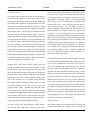
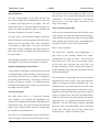
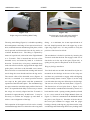
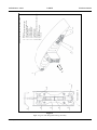
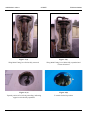
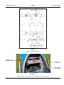
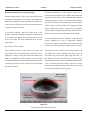
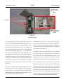
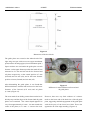
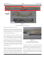
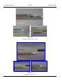
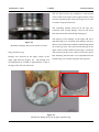
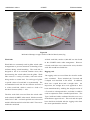
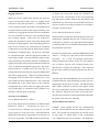
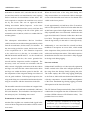
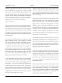
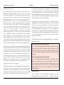
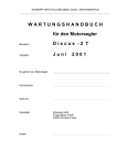
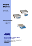
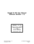
AAIB Bulletin: 5/2011
G-DBZZ
EW/C2010/08/02
ACCIDENT
Aircraft Type and Registration: SZD-24-4A Foka 4, G-DBZZ
No & Type of Engines: N/A
Year of Manufacture: 1966
Date & Time (UTC): 8 August 2010 at 1410 hrs
Location: Bicester Airfield, Oxfordshire
Type of Flight: Private
Persons on Board:
Crew - 1
Passengers - None
Injuries:
Crew - 1 (Fatal)
Passengers - N/A
Nature of Damage: Commander’s Licence: Commander’s Age: Commander’s Flying Experience: Aircraft destroyed
226 hours (of which 2.5 hours were on type)
Last 90 days - 3.7 hours
Last 28 days - 1.3 hours
Information Source: AAIB Field Investigation
Synopsis
History of the flight
During the second winch launch of the day, the wings of
General
the glider separated from the fuselage. The pilot sustained
A gliding club at Bicester Airfield had organised a week
fatal injuries in the resulting impact. The investigation
of gliding activity for 60 students from universities
determined that when the aircraft was rigged, the lower
around the country. Four friends, including the accident
bevel bolt of the wing main fitting had not fully engaged
pilot, had each brought a glider from Scotland to take
with the lower lug stack of the main spar joint and it was
part. The owner of G-DBZZ was not attending the
not possible to detect this condition. As a consequence,
event, but the pilot involved in the accident flight had
when the glider became airborne, the partially secured
flown the aircraft before and had observed the owner
joint was unable to sustain the wing bending moments
rig and de-rig the glider. The pilot had recently taken
associated with the winch launch and the lower bevel
out an insurance share in order to operate it as part of a
bolt failed. This allowed the lower attachment lugs to
syndicate arrangement. The owner conducted a verbal
disengage and the wings to fold upwards and separate
briefing on the handling of the aircraft with the accident
from the fuselage. Two Safety Recommendations have
pilot in the presence of an instructor and also provided
been made as a result of the investigation.
some notes on operating the glider. The accident pilot
Gliding Certificate
25 years
had also taken the Flight Manual home and studied it.
© Crown copyright 2011
44
AAIB Bulletin: 5/2011
G-DBZZ
Pre-launch activity
EW/C2010/08/02
time consulting the Flight Manual. When Pilot C felt
resistance, they stopped and adjusted the position of
the wingtips until the mechanism moved more freely
again before continuing. Pilot C was concerned that
there was no way of checking the mechanism had
reached full travel. The accident pilot and Pilot A
then located Section 7.8 ‘Assembly sequence’,
which contained a requirement for ‘40 half turns’ of
the mechanism to be made, which they pointed out
to Pilot C. It was decided that they would slacken
completely the wing main fitting mechanism and start
again. This was carried out, during which Pilot C, who
was operating the mechanism, felt no resistance and
carefully counted that the full 40 half turns required
by the Flight Manual were completed. As there was
no resistance felt, it suggested to them that the holes
were properly aligned. Pilot C made an additional
four to six half turns before feeling resistance, at
which point he then stopped.
The friends arose at about 0700 hrs on the morning of
the accident and rigged two of the four gliders before
attending the daily flying briefing at 0800 hrs. Following
the briefing and completion of documentation, the pilot
and friends re-read the flight manual Section 7.1 ‘Wing
assembling’ and commenced the rigging of G-DBZZ
and the other glider. The fuselage was withdrawn from
the trailer and placed on the rigging support. This was
designed to maintain the glider in an upright position but
one of the straps had broken, so one person held the tail
fin whilst the others withdrew the wings and laid them
out on the ground. One wing was placed in position
first, with the accident pilot supporting the wingtip and
another person (Pilot A) the wing root. Pilot A inserted
the spar root into the fuselage cutout and ensured that the
leading and trailing edge spigot bearings were positioned
over the bevel pins on the fuselage. Having done this he
The speed brace and tool were removed and the T-wrench
placed a trestle part way along the wing.
was inserted into the main fitting and the upper fuselage
cover for the mechanism access hole was locked in
Another pilot joined them and the other wing was
place. The tailplane and control linkages were secured
placed in position and a trestle placed under it. The
by Pilot A and the accident pilot carried out a duplicate
person (Pilot A) who had inserted the first wing spar
inspection to ensure this had been done correctly. A final
then operated the horizontal rotating bar which operated
check was made of the forward bevel pin adjustment
the forward bevel pins and was mounted on a bulkhead
bar, which could not be moved; the pilots assumed this
behind the pilot’s seat. This pushed the wings apart
indicated that the bevel pins were at their maximum
and so he returned it to its original setting with the
travel. Having taped over any joints, the accident pilot
wings flush with the fuselage. He then took over from
carried out a daily inspection and was assisted by another
the person holding the fin, who went to assist with
pilot whilst carrying out the positive control checks. The
rigging another glider. Another pilot (Pilot B) came
gliders were towed to the launch point and the accident
to assist and he took the left wingtip, with the accident
pilot tried to contact the owner to ensure they had carried
pilot holding the right wingtip; Pilot A supported the fin
out the rigging correctly. The owner did not answer the
whilst another pilot (Pilot C) operated the wing main
call and so a message was left for him.
fitting locking mechanism using the speed brace and a
rigging tool provided in the rigging tool box.
The first launch
As none of the pilots had rigged the glider before,
the accident pilot, and those assisting, spent some
The weather at Bicester was good with the surface wind
© Crown copyright 2011
variable at less than 5 kt, visibility in excess of 10 km
45
AAIB Bulletin: 5/2011
G-DBZZ
EW/C2010/08/02
and cloud scattered at 4,500 ft. Runway 36 was in use
adjustment mechanism could not be moved anymore,
and the pilot of G-DBZZ was planning to attempt a
the bevel pins were fully extended in the spigot
distance flight of 317 km over a set route. For this
bearings.
reason, the glider logger was operating.
Second launch
The glider was moved forward to the launch point and
The duty instructor checked what type of launch was
the duty instructor asked the pilot what type of glider
required and the pilot responded that the climb would
it was. The pilot told him and added that it launched
be at 60 kt and similar to an ‘Astir’, but gently initially
like an ‘Astir’. The instructor was not familiar with
for the ground roll. The pre-flight and control checks
the type and so instructed the winch driver to launch it
were performed and the canopy checked for security.
like a ‘K8’. After a short ground run the glider lifted
The launch cable with the correct weak link was
off and adopted a climbing attitude. Shortly after, the
attached and the launch initiated following a radio call
nose was lowered, which was the signal to the winch
to the winch driver. The acceleration and rotation into
driver to increase the launch speed, which he did. The
the climb appeared normal although, as the aircraft
glider continued to climb and released from the cable.
climbed, some witnesses thought it appeared fast. The
The pilot had not achieved the hoped for height from
glider yawed to the right but it was not clear if this was
the launch and was unable to locate any thermals.
the commencement of the yawing signal to slow down.
Following four orbits, the glider was flown around the
The winch driver reduced power, as he normally would,
circuit and established on the final approach. As the
and the glider continued the climb a little steeper and
airbrakes were extended, the canopy opened and moved
faster than normal. Witness estimates of the height
forward on its rails. The pilot held onto the canopy with
at which the next sequence of events occurred varied
one hand, to prevent it opening further, and controlled
between 600 ft and 1,000 ft, but the described sequence
the glider with the other hand. As a consequence, the
was generally similar.
glider was landed with the airbrakes extended but the
touchdown was without incident. The pilot was shaken
The glider was still on the launch when the left wing
by the experience but was happy to continue flying, so
bent up approximately 20° and the aircraft banked
the glider was towed back to the launch point.
slowly to the left. The right wing then bent up by a
similar amount.
At this point the owner returned the accident pilot’s call
released from the winch cable at this point but the
and they discussed the rigging and the canopy coming
wings separated from the fuselage, remaining attached
open. The pilot and friends had some light refreshments
to each other at the main spar joint. The fuselage
before preparing the glider for a subsequent launch.
adopted a steep nosedown attitude before striking the
The owner telephoned a second time to suggest that
ground. The wings descended at a slower rate falling to
the canopy opening may have been associated with
the ground short of the fuselage. A number of persons
the opening of the airbrakes. As a result of the two
were very quickly on the scene but the accident was not
telephone conversations, the pilot was reassured
survivable.
that they had followed the correct rigging procedure
and understood that providing the forward bevel pin
© Crown copyright 2011
The glider appeared not to have
46
AAIB Bulletin: 5/2011
G-DBZZ
Pilot information
The ailerons, elevator and rudder are fabric covered
and the wings are of stressed skin laminated plywood
construction. The wings do not have a conventional
spar; however a root spar allows connection of the
wing to the fuselage.
The pilot started gliding in July 2001 and up until
the accident flight had accumulated 226 hours and
19 minutes total flying time in 531 flights. This was
broken down into; 75 hours 49 minutes on single-seat
Wing attachment philosophy
gliders, P1 multi-seat gliders10 hours 53 minutes and
P2 multi–seat gliders 139 hours 37 minutes.
There are three attachment points for the wings of the
Foka 4 glider: the wing root main attachment fittings,
The pilot held A and B British Gliding Association
which form the main spar joint and resist wing bending
(BGA) certificates issued in September 2002 and a BGA
loads; trailing edge fixed bevel pins, and leading edge
Bronze award in September 2003, with a qualifying
movable bevel pins, which resist torsional loads.
cross-country in April 2004. The pilot also held a
Wing to wing attachment
BGA Silver award, completing the height element in
May 2004, distance in August 2004 and duration in
The aircraft has a shoulder wing configuration. A
November 2004.
spar cutout in the fuselage, behind the cockpit,
accommodates the wing root spars. Two latches on
The first flight on the Foka 4 was on 19 June 2010 and in
the forward wall of the spar cut-out engage catches
four flights a total of 2 hours 30 minutes were flown.
on the wing roots, allowing each wing half to be
Medical and pathological information
mounted separately thereby reducing the number of
people required to rig the aircraft. The latches have no
A post-mortem examination revealed that the pilot had
structural significance.
no medical history which would have been relevant to
the accident and there was no evidence of significant
The left wing has a single upper and a lower horizontal
pre-existing natural disease. Toxicology revealed no
attachment lug at the root spar. The right wing has a
evidence of drugs or alcohol. It concluded that the
double set of upper and lower attachment lugs. The
pilot died of multiple injuries which were caused when
attachment lugs of each wing meet in the centre of the
the glider struck the ground.
fuselage forming an upper and lower lug stack. Correct
alignment of the lugs in the upper lug stack is achieved
Aircraft description
using an ‘L-shaped’ tool. This tool is inserted through a
The SZD 24-4A Foka 4, a single-seat standard
small access hole in the top of the fuselage and into the
class sailplane, was designed and manufactured by
upper lug stack. It is ‘joggled’ until the lugs come into
Szybowcowy Zaklad Doswiadczalny (SZD) Bielsko in
alignment. The spar joint is then secured by expanding
Poland in the 1960s. The type is no longer in production
the bolts of the wing main fitting, which is mounted
and the Type Certificate for the aircraft is currently held
on the end of the right wing root spar, between the
by a Polish aircraft manufacturer.
attachment lugs. Figure 1(a) and 1(b) refer.
The Foka 4 is of predominantly wooden construction,
with a fibreglass composite forward fuselage section.
© Crown copyright 2011
EW/C2010/08/02
47
AAIB Bulletin: 5/2011
G-DBZZ
EW/C2010/08/02
Figure: 1 (a)
Figure: 1(b)
Right wing root with Wing Main Fitting
Fuselage spar cut-out, right wing installed;
access hole visible in top of fuselage
The wing main fitting (Figure 2) is a double expanding
fitting – as a minimum, the 8 mm tapered lead-in of
bolt arrangement consisting of two tapered steel bevel
the bolt should protrude above the upper lug on the
bolts, mounted between aluminium guide plates, which
right wing (Figure 4a). It is not possible to verify the
travel upwards and downwards into the lug stacks on
position of the lower bevel bolt.
a hollow threaded screw. The fitting is operated by
means of a special tool, referred to in the Flight Manual
The mechanism is locked in position by inserting the
as a ‘T-wrench’. This is inserted into the bore of the
T-wrench such that the bent arm engages with one of
threaded screw, and turned by hand in a clockwise
four holes cut in the top of the spars (Figure 4b.) A
direction. Vertical slots, or keyways, machined along
sprung access panel is then placed in the access hole.
each side of the bevel bolts, engage with the edge of the
Wing to fuselage attachment
guide plates, such that as the threaded screw rotates,
the bevel bolts are restrained from turning and instead
Two fixed and two movable horizontal bevel pins are
travel along the screw threads and into the lug stacks.
mounted on the fuselage in the area of the wing root
The central collar of the threaded screw (Figures 3a
and these are positioned to engage with self-aligning
and 3b) is restrained in a central position between
spigot bearings (Items 8 and 9, Figure 5) on the wing
two stops on the guide plates such that symmetrical
root ribs when the wings are offered up to the fuselage.
expansion of the bolts takes place. The attachment lugs
The rear set of bevel pins are fixed (Item 5, Figure 5).
are taper‑reamed to match the taper profile of the bevel
The forward set of bevel pins (Item 3, Figure 5) are
bolts. To expand the bolts fully it is necessary to ensure
movable and are extended and retracted by means of a
the wings are correctly aligned and the T-wrench is
horizontal bar with a sprung rotating handle (referred
operated for approximately 40 half turns. It may be
to as a ‘screw wrench’ in the Flight Manual) (Item 10,
necessary to oscillate the wingtips up and down to
Figure 5.) This bar is mounted on the bulkhead behind
achieve correct alignment of the lugs.
the pilot’s seat (Figure 6). Rotation of the bar drives
the bevel pins outboard to engage with the spigot
Full expansion of the upper bevel bolt can be visually
bearings, thereby reducing any gaps between the wing
confirmed through the access hole above the wing main
and fuselage and eliminating unnecessary loading in the
© Crown copyright 2011
48
© Crown copyright 2011
49
Figure 2
Right wing root with Wing Main Fitting Assembly
12
11
10
8
13
9
View on arrow A
2
3
4
A
5
6
1.
2.
3.
4.
5.
6.
7.
8.
9.
10.
11.
12.
13.
7
1
Rib no 1
Upper right wing attachment lugs
Lower right wing attachment lugs
Forward spigot bearing
Aft spigot bearing
Airbrake control lever
Aileron control lever
Upper bevel bolt
Lower bevel bolt
Right and left threaded screw with central collar
Guide plate
Guide plate fixing spigot
T-wrench
Right Wing Root with Main Wing Fitting Assembly
AAIB Bulletin: 5/2011
G-DBZZ
EW/C2010/08/02
AAIB Bulletin: 5/2011
G-DBZZ
EW/C2010/08/02
Figure: 3 (a)
Figure: 3(b)
Wing Main Fitting, bevel bolts fully retracted
Wing Main Fitting, bevel bolts fully expanded and
T-wrench inserted
Figure: 4 (a)
Figure: 4(b)
Tapered portion of bevel bolt protruding, indicating
upper bevel bolt fully expanded
T-wrench locked in position
© Crown copyright 2011
50
AAIB Bulletin: 5/2011
G-DBZZ
EW/C2010/08/02
6
A–A
2
“
7
T”
2
9
5
5
A
A
1
8
B
B
3
B–B
10
Figure 5
Wing attachment philosphy
Right forward
horizontal bevel pin
Rotating 'screw
wrench'
Securing spigot
and locking disc
Figure: 6
Horizontal bar (‘screw wrench’) which operates forward bevel pins
© Crown copyright 2011
51
AAIB Bulletin: 5/2011
G-DBZZ
wing to fuselage joints. Full tightening of the forward
EW/C2010/08/02
‘1. Open the canopy and inspection panels
bevel pins can be facilitated by oscillating the wingtips
on fuselage top, remove the top covering,
forward and aft. A securing spigot engages a locking
remove tail cup.
disc mounted on the rotating handle to lock the forward
2. Clean and cover with technical Vaseline
bevel pins in position (Figure 6).
all working surfaces of fittings, bolts, pins,
The Aircraft Flight Manual (AFM)
seats and of control drive joints.
The Aircraft Flight Manual contains the information and
3. Unlock the screw handle of the front
limitations for the operation of the glider. Section 7,
bevel bolts in the fuselage /3 fig. 9 /[refer
‘Assembling and Disassembling’, explains the rigging/
to Item 3, Figure 5], and pull the bolts
de-rigging of the glider and is broken down into a number
together by turning the screw handle in
of sub-sections.
the right direction till stop /looking from
left wing half/ i.e. in direction opposite to
Paragraph 7.1, ‘Wing assembling’, provides a technical
marked arrow.
description of the assembly of the wings to the
fuselage. It refers to numbered components shown on
4. Pull together the bevel bolts in the fitting
an engineering drawing and explains how the various
of spar root of right wing half by turning
components fit together, as well as what actions are
with “T” wrench in left direction till stop,
needed to operate the assembly mechanisms. It does not
i.e. in direction opposite to marked arrow.
contain any specific sequence of assembly, cautions or
Remove “T” wrench from the fitting.
methods of assuring proper alignment of the attachment
5. Insert any wing half into fuselage and
lugs for the bevel bolts. This information is provided
two pages later in Paragraph 7.8.
attach provisionally the spar root by means
Paragraphs 7.2 to 7.7, cover ‘Horizontal tailplane
which is accessible from upper luggage
fitting’, ‘Tools’, ‘Auxiliary items’, ‘Assembly team’,
compartment. Insert in the same way the
‘Assembly time’ and ‘Disassembly time’ respectively.
other wing half.
of lock 1/ fig. 9/ [refer to Item 1, Figure 5],
6. Align accurately fitting holes by means
Paragraph 7.8, ‘Assembly sequence’, provides detailed
of duralumin “L” wrench.
instructions for attaching the wings to the fuselage and
wrench /fig. 9/
the relevant extract is set out below:
Insert “T”
[refer to Figure 5] and
put apart the bevel bolts. Turning of the
wrench to the right, in accordance with
marked arrow. Obtain full tightening of
bevel bolts by unloading the wing tips and
performing small oscillations. Check the
play /if any/ by finger pressing to the upper
bevel bolt. After full tightening of bolts set
© Crown copyright 2011
52
AAIB Bulletin: 5/2011
G-DBZZ
EW/C2010/08/02
ground run of a takeoff would be captured. The trigger
the “T” wrench so as to insert the end of
to stop the recording was if the altitude and speed did
bent handle into hole in the fitting. Put the
not vary by more than 50 m or 5 km/hr, respectively, in
upper inspection disc and set it according
the last 90 minutes.
to red marks.
The recorder captured the complete flight prior to the
Caution:
accident flight.
The “T” wrench is to be handled by hand only
The recording stopped 19 minutes
after landing, indicating that the unit was manually
not by tools! The operation is facilitated by
switched off rather than automatically stopped. The
hand holding the wrench flange with left hand.
technology is such that had the unit been switched back
Full pushing apart of the bevel bolts requires
on, appropriate date/time stamped data would have
ca.40 of half-rotations.
been present in the memory of the unit even if power
had subsequently been lost. There was no such data
7. Unlock the screw handle of front bevel
relating to the accident flight, indicating that the unit
bolts in the fuselage and take bolts apart
had not been switched on before the accident flight.
by turning of handle to the left /looking
from the left wing half/ i.e. in direction
Accident site and wreckage examination
indicated by arrow. Full tightening may
Wings
be facilitated by horizontal loading of wing
Examination of the wreckage showed that wings had
tips in rearward direction /hold on the
become detached in flight and had fallen separately
fuselage/. Secure the handle. Check the
from the fuselage, coming to rest inverted to the right
play of the connection by observing a gap
of Runway 36.
between fuselage and wing when the wing
tips are loaded horizontally.
The wings (Figure 7), which were still attached to each
other, were largely intact except for a 2.15 m section of
Caution:
the left wing inboard trailing edge, which had detached
The handle is to be operated by hand only,
on impact with the ground. Examination of the wing
without any tools!
root fitting in the as-found inverted position, revealed
that the lower bevel bolt was only partially engaged in
Overstressing of handle causes shearing-of of
the lower right wing attachment lugs and the lower left
safety pin. A new safety pin is to be made from
wing attachment lug was disengaged from the lug stack
soft steel wire Ǿ 2 mm /steel SP 1A/.’
(Figures 8a and 8b).
Recorded data
After turning the wings over into their correct orientation,
An ‘EW microRecorder’ unit was recovered from the
examination revealed that although the upper attachment
accident site. The unit was designed to automatically
lugs of the right wing had splayed apart, the wings had
start and stop recordings depending on speed and
remained connected by the upper lug stack and bevel
altitude changes. The start criteria were such that the
© Crown copyright 2011
bolt. The T-wrench was still installed in the internal
53
AAIB Bulletin: 5/2011
G-DBZZ
EW/C2010/08/02
A
Figure 7
G-DBZZ Wing assembly (inverted)
B
Figure 8 (a)
Figure 8 (b)
View on Arrow A from Figure 7
View on Arrow B from Figure 8 (a)
diameter of the threaded screw and locked in position
It was noted that the upper and lower bevel bolts had
(Figure 9). Both the T-wrench and the threaded screw of
not expanded symmetrically along the threaded screw
the wing main fitting were distorted where they passed
and the central collar of the threaded screw had been
through the upper bevel bolt and lug stack.
dislodged from the cut-out in the guide plates.
© Crown copyright 2011
54
AAIB Bulletin: 5/2011
G-DBZZ
impact.
EW/C2010/08/02
The tail section remained attached until
ground impact. It was found adjacent to the fuselage,
remaining connected via the elevator and rudder
cables. The fuselage wreckage was oriented on an
approximate heading of 349º. The front skid from the
underside of the fuselage was firmly embedded in the
in the ground. These facts, together with the absence of
any ground marks leading up to the wreckage, indicate
a near vertical impact.
The rear fixed bevel pins had remained attached to the
fuselage structure, and were protruding approximately
16 mm. The forward bevel pins on the rotating horizontal
bar were also intact and were protruding 17 mm. The
rotating bar was bent, and the securing spigot was not
engaged in the locking disc. A small witness mark
was evident where the spigot had contacted the face of
the locking disc. The wooden bulkhead on which the
rotating bar was mounted was largely intact; however,
the surrounding fuselage structure had been disrupted.
The winch cable
Figure 9
The winch cable, drogue and associated linkages were
Wing main fitting in correct orientation
located approximately 40 m forward, and to the left of
the location of the wings. All components in the winch
The self-aligning spigot bearings on the left and right
cable arrangement were intact and in good condition. A
wing root ribs were examined. All displayed evidence
Tost No 4 blue weak link and a Tost No 1 black weak
of fresh damage around the edges of the bearing
link were found to be connected in series, between the
housing, consistent with the bevel pins being dislodged
launch strop which attached to the aircraft and the cable
from their seats under considerable load. This indicates
parachute, by means of a quick release hook and ring.
that the bevel pins were engaged at the time the wing
separated from the fuselage.
The wreckage was removed the following day
for detailed examination at the AAIB’s facility in
Fuselage
Farnborough.
The fuselage struck the ground inverted and at high
speed, approximately 160 m forward of the wings,
in the direction of the launch. The fuselage structure
forward of the wing was severely disrupted in the
© Crown copyright 2011
55
AAIB Bulletin: 5/2011
G-DBZZ
Detailed examination of wing main fitting
EW/C2010/08/02
Detailed examination of the fracture surface by a
Scanning Electron Microscope (SEM) showed that the
Detailed examination of the wing main fitting using
majority of the fracture surface exhibited shear dimples,
Computed Tomography (CT) images, determined that
indicating a failure in shear. Some mechanical damage
there was no damage to the threads of the threaded screw
was also evident and was most likely the result of contact
or bevel bolts, which may have prevented symmetrical
with the lugs or contact between the opposing fracture
expansion of the bevel bolts.
surfaces during the failure. Both the shear dimples
and mechanical damage indicated that the direction of
A specialist company, under the supervision of the
failure was across the minor diameter of the ellipse.
AAIB, conducted a detailed metallurgical examination
of the wing main fitting, the fractured portion of the
It was noted that the inner diameter of the sheared
lower bevel bolt, the wing attachment lugs and the
section exhibited an area of mechanical damage
guide plates.
(Figure 10), which is consistent with contact with the
Bevel Bolt Fracture Surfaces
end of the T-wrench during the failure of the bevel bolt.
The fractured portion of the lower bevel bolt was
The fracture surface of the lower bevel bolt (Figure 11)
approximately 8 mm in length and was observed to be
was found to be positioned flush with the top face of
elliptical in shape, having been deformed during the
the bottom lug in the lower right wing lug stack. In
failure. It exhibited a fracture surface on one face and
this position, the left wing lower lug could not have
a machined finish on the other indicating that it was the
disengaged, therefore it was concluded that the threaded
8 mm tapered lead-in at the bottom of the bolt which
screw, and hence both bevel bolts, must have moved
had been fractured.
downwards by approximately 8 mm after the lower left
wing lug separated from the lug stack.
Witness mark
from T-wrench
Fracture Face
Run-out of
vertical groove
Machined Face
Figure 10
Fractured section of lower bevel bolt
© Crown copyright 2011
56
AAIB Bulletin: 5/2011
G-DBZZ
EW/C2010/08/02
RH Wing Top
RH Wing Top Lug
Lug
of Lower Lug
of Lower Lug
Stack Stack
Keyways
Keyways
8 mm
Fracture surface
RH
Wing
Bottom
RH
Wing
Bottom
Lug
of of
Lower
Lug Lug
Lug
Lower
Stack
Stack
Figure 11
Wing Main Fitting
The central locating collar of the threaded screw was
Dimensional checks were carried out on the upper
bevel bolt and key dimensions are shown on Figure 12.
A witness mark on the bolt indicated where it normally
came into contact with the upper lug stack. Both bolts
are assumed to be identical.
not in its correct position within the guide plate recess.
The lower face of the collar was approximately 8 mm
below the lower land of the recess. The keyways of
both the upper and lower bevel bolts were disengaged
from the guide plates (Figure 11). The ends of the
The depth of the keyway on both bolts was measured
bevel bolt keyway (Figure 10) were observed on the
as 2.3 mm within the cylindrical section, running out
sheared portion of the lower bevel bolt at approximately
to 0.5 mm at the end of the middle taper section. The
diametrically opposite sides of the minor diameter of
dimension between the flats of the keyways on the
the ellipse. It was therefore concluded that the keyway
cylindrical section of the bolts was therefore 24.1 mm.
of the lower bevel bolt was not engaged in the guide
plates at the time the left lower lug pulled out of the
The width between the guide plates was measured
lug stack.
between the limits of vertical movement of the upper
and lower bevel bolts and noted as varying between
There were 28 threads showing on the upper part of the
28.1 mm and 29.1 mm in the region of the upper bevel
threaded screw but only 17 threads visible above the
bolt and between 28.9 mm and 28.5 mm in the region
lower bevel bolt. This suggests that the lower bevel bolt
of the lower bevel bolt. The guide plate spacing was
disengaged from the guide plate approximately 11 turns
therefore greater in places than the maximum diameter
before the upper bevel bolt disengaged.
© Crown copyright 2011
of the bolts and the distance between the keyways.
57
AAIB Bulletin: 5/2011
G-DBZZ
EW/C2010/08/02
Figure 12
Dimensions of the bevel bolts
The guide plates are secured to the inboard end of the
right wing root spar with two screws (upper attachment
Aft plate
FWD plate
point) and two locating spigots (lower attachment point.)
Spacer washers are used under the guide plate on each
fastener. At the upper fastener position the stand-off was
measured as 5.1 mm and 4.8 mm for the forward and
Thin spacer
Thick spacer
aft plates respectively; at the central position 6.7 mm
(forward) and 5.9 mm (aft); and at the lower fastener
position 4.2 mm (forward) and 6.4 mm (aft).
After dismantling the guide plates, it was found that
Figure 13
different thickness washers had been used on the lower
Difference in stand-off between forward and
aft guide plates
fasteners of the forward (0.55 mm) and aft plates
(1.9 mm) (Figure 13).
The wear marks from sliding contact between the bevel
However, there was very little evidence of a witness
bolt keyways and the edges of the forward and aft guide
mark on the lower end of the back face of the aft guide
plates were examined. The contact depth appeared to
plate, suggesting minimal engagement of the guide plate
vary from approximately 2.2 mm - 2.4 mm towards the
with the keyway of the lower bevel bolt. There also
centre of the plates, to 1.2 mm -1 .4 mm at the ends.
appeared to be some edge rounding ( Figure 14).
© Crown copyright 2011
58
AAIB Bulletin: 5/2011
G-DBZZ
EW/C2010/08/02
Minimal
contact
Minimal
contact
evidence
evident
Back
BackFace
Face
UP
Figure 14
Wear marks on back face of aft guide plate
Damage to guide plate and central collar
Examination of the guide plates showed that mechanical
Back Face
damage was present on the edge of the back face of the
forward and aft guide plates over a length of 8 mm from
Damage
the lower land of the central recess.
This corresponds to the position in which the central
collar of the threaded screw was found. However, the
UP
first 1 - 2 mm of damage on both forward and aft plates
is consistent with rotational movement of the collar
(horizontal scoring) rather than vertical movement of the
Figure 15
collar. This indicates that the collar had been damaging
Forward guide plate below recess
(Aft guide plate exhibits similar damage)
the lower edge of the guide plate recess on both forward
and aft guide plates while the mechanism was being
operated (Figure 15).
the upper land of the recess. The mechanical damage
Mechanical damage was also evident above the guide
rubbing against the collar during rotation (Figures 16
plate recess. Unlike the damage below the recess, which
and 17).
occurred only on the back face edge, the damage above
horizontal scoring (Figure 18), which is consistent with
the recess was evident on both the visible and back
the collar moving up out of the recess as the T-wrench
face edges for a distance of approximately 5 mm from
was turning.
© Crown copyright 2011
resulted in horizontal scoring of the plate, consistent with
59
Examination of the collar showed similar
AAIB Bulletin: 5/2011
G-DBZZ
Front Face
UP
Front Face
Back Face
Figure
Figure 16: Forward
guide 16
plate above recess
Forward guide plate above recess
Front Face
UP
Front Face
Back Face
Figure
Figure 17: Aft
guide 17
plate above recess
Aft guide plate above recess
© Crown copyright 2011
60
EW/C2010/08/02
AAIB Bulletin: 5/2011
G-DBZZ
EW/C2010/08/02
The left hand (centre) lug exhibited a semi-circular
witness mark on the upper surface approximately 6 mm
from the right hand edge of the hole (Figure 20) as well
as radial scoring from the hole.
The remaining damage observed on the lugs was
consistent with scoring damage caused as the bevel
bolt sheared and the left hand lug disengaged.
The majority of the damage on the upper and lower
right hand lugs was consistent with damage caused as
Figure 18
the lower bevel bolt sheared and the left hand lug pulled
Mechanical damage observed on surface of collar
out of the lug stack. The semi-circular damage on the
upper surface of the left hand (centre) lug is consistent
Wing attachment lugs
with contact with the lower surface of the lower bevel
bolt indicating that the bolts were expanded while the
Damage was observed on the upper surface of the
left hand lug was not fully aligned in the lug stack.
upper right hand lug (Figure 19). The damage was
circumferential for a width of approximately 2 mm at
the edge of the LH side of the hole.
Figure 19: Mechanical damage observed onFigure
upper 19
surface of upper right hand lug
Mechanical damage observed on upper right hand lug
© Crown copyright 2011
61
AAIB Bulletin: 5/2011
G-DBZZ
EW/C2010/08/02
Radial
scoring
Semi-circular
witness mark
Figure 20
Mechanical damage on upper surface of the left hand (centre) lug
Weak links
A black weak link, rated to 1,000 daN was also found
in the G-DBZZ winch cable arrangement. However
Weak links are commonly used in glider winch cable
as both weak links were connected in series, the blue
arrangements to prevent structural overloading of the
weak link would have failed first.
airframe during winch launching. The weak link is
Rigging tools
designed to fail if an overload situation arises, thus
disconnecting the winch cable from the glider. Weak
The rigging tools recovered from the aircraft’s trailer
links come in a variety of colours, with each colour
were examined.
being rated to a certain load. For each type of glider
L-shaped tool described in the AFM.
a specific colour of weak link is recommended. The
In addition,
there was a speed brace and a straight drive.
recommended weak link for the SZD-24-4A Foka 4
On
inspection, the straight drive tool appeared to have
is a blue weak link, which is rated to a load of to
been manufactured by welding the straight section of
600 deca Newtons (daN) +/- 10%.
a T-wrench to a hexagonal-drive, such that it could be
used in conjunction with a standard speed brace. The
The blue weak link recovered from the winch cable
Type Certificate holder confirmed that this was not a
used to launch G-DBZZ, when tested, failed at a tensile
manufacturer approved tool. This tool and the speed
load of 621.7 daN. A control specimen was also tested
brace had been included with the rigging tools when
and this failed at tensile load of 620.9 daN. These were
the owner purchased the aircraft.
within the rated load.
© Crown copyright 2011
These included the T-wrench and
62
AAIB Bulletin: 5/2011
G-DBZZ
Rigging experience
EW/C2010/08/02
to inspect the wing main fitting for ovalisation of
the bevel bolts, non-linearity of the cone-generating
When the owner acquired the aircraft, the previous
line and surface contact between the bevel bolts and
owner had provided some notes on rigging; these
attachment lugs. The annex also included instructions
referred to using the speed brace. Consequently, the
on how to remove any observed defects in accordance
owner routinely used the speed brace and modified tool
with the overhaul manual.
to operate the bevel bolts of the wing main fitting. His
Service Bulletin BE-06/4A/80 ‘Foka 4’
experience of rigging the aircraft was that considerable
care was required to ensure the wing attachment lugs
The Foka 4 Service Manual, issued at the time of aircraft
were properly aligned. Little force was required to
manufacture stipulated that the first overhaul was due
operate the speed brace on the wing main fitting when
at 650 hours or within 5 years and indicated that further
the lugs were fully aligned. Upon expanding the bevel
overhaul periods were to be defined subsequently based
bolts, if any resistance was encountered he considered
on operational experience.
it imperative to stop and wind the bolts back in, before
attempting to realign the lugs. The process could then
In 1980 the manufacturer published SB BE-06/4A/80
be commenced again, with the appropriate number of
‘Foka 4’ – ‘Changes of repair time periods and further
turns being counted. Given the limited visibility of the
operation’.
wing main fitting, the primary indicator of whether the
As a result of prolonged observation,
technical inspections and the results of a wing fatigue
rigging was progressing as expected was the mechanical
test on Foka 4 aircraft, new overhaul periods were
‘feel,’ or feedback, through the rigging tool. The owner
introduced at 1,300 hrs and 1,900 hrs. These replaced
believed that the T-wrench was to be used only as a
the previous overhaul periods described in the Service
locking mechanism to secure the wing main fitting at the
Manual.
end of the rigging process. When he had demonstrated
the rigging of the aircraft to the accident pilot, it was
This SB required that SB BE-005/75 be carried out and
in accordance with his normal practice. The owner had
in addition that the wing main fitting and spar root was
anticipated that in the initial stages of the syndicate
inspected for the presence of cracks. The SB indicated
arrangement they would jointly be rigging the glider.
that a further extension to the life of the glider would
The accident pilot, as a member of the syndicate, was
have to be endorsed by the Type Certificate Holder and
entitled to take the glider to Bicester.
the ‘authority’ based on the results of the inspection.
The SB also introduced certain operational limitations
Aircraft service bulletins
for gliders with more than 1,900 hrs.
Service Bulletin BE-005/75 ‘Foka 4’
Aircraft maintenance history
In 1975 the manufacturer issued Service Bulletin (SB)
BE-005/75 ‘Foka 4’ – ‘Introducing the Annex Nr 1
G-DBZZ, serial number W-308 was manufactured
to Technical Service Manual concerning the extended
in 1966, and transferred onto the British register in
range of glider periodic inspections’, which introduced
1967. The aircraft was acquired by the current owner
additional maintenance requirements on the basis of
in July 2007, at which point it had accumulated
in-service experience. This SB included requirements
1,913 flight hours and 1,353 launches. One flight was
© Crown copyright 2011
63
AAIB Bulletin: 5/2011
G-DBZZ
EW/C2010/08/02
undertaken in October 2007, and after that the aircraft
When the bevel bolts of the wing main fitting were
was not flown until it was transitioned to a non‑expiring
fully retracted there were no threads visible in the upper
EASA Certificate of Airworthiness in June 2008. The
section of the threaded screw however five threads were
work required to complete the transition was carried
visible on the lower portion.
out by the owner who was an approved British
Gliding Association (BGA) Inspector. At the time
It took approximately 62 half turns of the T-wrench to
the aircraft was transitioned the owner could not find
achieve full expansion of the bevel bolts rather than the
any information relating to the life of the glider, and
40 half turns quoted in the flight manual. With the bolts
assumed it to be 12,000 hrs, which is a standard life for
fully expanded, there were 30 threads visible below the
wooden gliders.
upper bevel bolt and 37 threads visible above the lower
bevel bolt. The upper and lower bevel bolts protruded
The subsequent Airworthiness Review Certificate
from the lug stack by 12 mm and 13.5 mm respectively.
(ARC) renewal was carried out in August 2009, by which
time the aircraft had 1,924 hrs and 1,373 launches. In
Additionally, it was noted that the aircraft had been
the intervening period the owner had become aware
modified to incorporate an access hole, which would
of the requirement for a Life Extension inspection
allow inspection of the position of the lower bevel bolt
to be carried out at 1,900 hrs, in accordance with
with a torch and inspection mirror. This enables positive
SBs BE‑064A/80 and BE-005/75. As the aircraft had
identification that the lower bevel bolt is fully engaged
already passed 1,900 hrs, the owner grounded the
in the lug stack during rigging.
aircraft until the inspection could be completed. The
Previous accidents
necessary work was carried out coincident with the
ARC renewal. Negligible ovalisation of the bevel bolts
In March 2007 an SZD-36-A ‘Cobra’ aircraft, registration
and lugs was noted and the contact between the bolts
N6SZ, crashed in the USA after in-flight separation of
and lugs was within the limits quoted in the SB. All
the wings from the fuselage, fatally injuring the pilot.
the components of the wing main fitting were observed
The Cobra employs the same wing rigging philosophy
to be in good condition. Following the inspection, the
as the Foka 4, albeit with some dimensional differences
wing main fitting was reassembled and mounted on the
of the key components. As with G-DBZZ, misalignment
wing in accordance with the instructions in the SB.
of the lower attachment lugs during rigging prevented
full expansion of the lower bevel bolt.
The next ARC renewal was carried out on 2 August 2010,
by which time the aircraft had accumulated 1,940 hours
The US National Transportation Safety Board (NTSB)
and 1,390 launches. This included a visual inspection of
conducted an investigation into the circumstances of the
the main spar joint. No findings were noted.
accident (NTSB reference ATL07LA066 refers). The
probable cause was cited as:
Examination of other similar aircraft
‘The pilot’s improper installation of the left wing
Another Foka 4 glider was examined and rigged in the
attachment pin, which allowed it to disengage
course of the investigation and a number of observations
during cruise flight, resulting in wing separation.’
were made.
© Crown copyright 2011
64
AAIB Bulletin: 5/2011
G-DBZZ
EW/C2010/08/02
There were no safety recommendations resulting from
between the attachment lugs of the left and right
the investigation.
wings is achieved, and that the T-wrench is operated
for the required number of turns. Correct alignment
This accident prompted the owner of a UK registered
of the upper attachment lugs is facilitated by using the
Cobra to inspect his aircraft, and his findings led to
L-wrench tool and can be verified visually, however
the BGA issuing an awareness item on their Technical
alignment of the lower lugs cannot. If the wings’ tips
News Sheet (reference 02/2007), advising owners of
are held too high or if the wing is trestled too close to
Foka and Cobra gliders that damage incurred during
the root, this may cause the lower lugs to be misaligned.
rigging could cause failure of the wing main fitting. A
Misalignment of the lugs may therefore only become
possible cause was noted as holding the wings too high
apparent when the bevel bolts are being expanded.
during rigging.
Therefore, when operating the T-wrench to expand the
bevel bolts, it may be necessary to unload the wingtips
In June 1968 an SHK 1 glider, registration BGA 1390
and perform small oscillations to progressively achieve
crashed, fatally injuring the pilot, at Doncaster
correct alignment.
Aerodrome, UK. During rigging the bevel bolts
jammed against the lugs of the opposite wing due to
If the lugs are not correctly aligned it is possible for the
misalignment; this was at less than the requisite number
of turns on the operating mechanism.
expanding bolts to foul against the left wing (centre)
The wings
lug and not expand fully into the lug stack.
separated from the fuselage during the subsequent
The
primary indications of any such misalignment would be
winch launch.
resistance encountered while operating the T-wrench,
in particular if the T-wrench stopped rotating prior to
Analysis
the requisite number of turns.
General
Incorrect tooling
From the aircraft examination and the detailed
metallurgical investigation, it is apparent that the
When operating the approved T-wrench, using only
lower bevel bolt of the wing main fitting had not fully
hand force, any resistance is likely to be immediately
engaged with the lower lug stack during rigging. This
evident. The flight manual emphasises the importance
significantly reduced the load-carrying capability of
of using only hand force to turn the T-wrench. The
the joint. As a consequence, when the glider became
required number of turns is quoted in half turns,
airborne the partially secured joint was unable to sustain
because articulation of the wrist is limited to a half turn
the wing bending moments associated with the winch
at a time. The effect of using the speed brace with the
launch and the lower bevel bolt failed in shear. This
modified tool was that the tactile feedback would have
allowed the lower attachment lugs to separate and the
been reduced. Additionally, because of its cranked
wings to fold upwards and detach from the fuselage.
shape, the speed brace would have provided significant
mechanical advantage when turning the bevel bolts
Rigging of the aircraft
and it would have been much easier to overcome any
In order to fully expand the bevel bolts of the wing
resistance encountered using, what would seem to the
main fitting it is imperative that correct alignment
operator, as a very light force.
© Crown copyright 2011
65
AAIB Bulletin: 5/2011
G-DBZZ
EW/C2010/08/02
The precise history of the modified rigging tool and
Although the pilot attempted to call the owner to verify
speed brace are unknown, however they were provided
that the aircraft had been rigged correctly, the main
with the aircraft and routinely used to operate the wing
concern was relating to the operation of the rotating bar
main fitting. This suggests that many successful riggings
that adjusted the forward bevel pins rather than the main
had previously been performed using these tools.
fitting itself. By the time the pilot established contact with
the owner, the first circuit had already been completed
Experience of individuals
and although the rigging was briefly discussed, the pilot
The rigging team was not experienced in rigging this
was by that time somewhat preoccupied by the fact that
particular type of glider nor gliders with a similar rigging
the canopy had opened and this became the focus of the
philosophy. The accident pilot had observed the aircraft
conversation.
being rigged by the owner, but the extent to which the
Interpretation of flight manual
pilot participated in this rigging is not clear. During
this demonstration the owner used the speed brace and
While translation of the flight manual from Polish into
modified tool to expand the bevel bolt and used the
English has resulted in the manual being difficult to
T-wrench only as a locking tool. The pilot is therefore
read in places, all the information necessary to rig the
likely to have considered this to be the correct rigging
aircraft is largely present. The manual is however
method.
laid out in such a way that the information on ‘Wing
assembly’ and ‘Assembly sequence’ is split between
The owner’s experience of rigging the aircraft was that
two different sections and this evidently caused some
care was required to ensure the wings were correctly
confusion during the rigging. The manual is however
aligned and that the rigging process should be stopped
emphatic about the use of hand force only to operate
immediately if any resistance was encountered.
the T-wrench.
It
is not clear if, or to what extent, this experience was
communicated during the rigging demonstration.
No specific guidance is given on how to verify full
expansion of the bevel bolts other than the statement
Despite having previously read the flight manual, the
‘Check the play if any by finger pressing to the upper
accident pilot experienced some difficulty in locating
bevel bolt’. Additionally the manual contains no
the correct rigging information within the manual
reference to the fact that it is possible for the upper bolt
on the morning of the accident. However, when the
and lug stack to appear correctly assembled while the
information was correctly located, the instructions (with
lower joint is not.
the exception of the rigging tool) were followed. The
rigging team did not have any experience base for what
Observations made during the rigging of another
was ‘normal’ for this aircraft or what potential rigging
Foka 4, which required 62 half turns of the T-wrench
issues may be encountered. In particular, the person
to achieve full expansion of the bevel bolts, would
operating the speed brace had not participated in the
suggest that the figure of 40 half turns quoted in the
previous rigging and therefore would not have had any
flight manual can be considered an approximate figure
‘feel’ for what might be considered a normal amount of
only. It is likely that some variation can be expected
resistance and / or force required to operate the tool.
between individual aircraft to account for manufacturing
© Crown copyright 2011
66
AAIB Bulletin: 5/2011
G-DBZZ
tolerances, age and wear in the lugs. However, in the
With the central collar out of the recess, the bevel bolts
would no longer have expanded symmetrically. With
one or both bolts disengaged from the guide plate, the
bolts would have turned with the threaded screw rather
than travel along it.
case of G-DBZZ, the rigging team carefully counted
40 half turns and when it became apparent that the tool
was still rotating, added a few additional turns until it
stopped. The fact that the required number of turns had
been accomplished would have given them confidence
The relative positions of the bolts on the threaded screw
that the spar joint was correctly assembled.
indicated that both bolts did not disengage from guide
plates at the same time. The lower bolt disengaged
Sequence of events
approximately 11 turns prior to the upper bolt. It is only
Witness marks on the lower lug stack indicate that the
possible to give an approximate indication as it is not
expansion of the bevel bolts was performed while the
known whether any threads were visible when both bolts
lower left hand (centre) lug was not correctly aligned
were fully retracted. The upper bolt would therefore have
in the lower lug stack. The lower bevel bolt contacted
continued to travel along the threaded screw for some
the upper surface of the left (centre) lug in the lower
time, and this may explain why the upper bolt would have
stack which stopped it from moving further down into
appeared to be correctly located.
the lower stack.
As rotational scoring was present above the recess on
The resistance encountered by the lower bevel bolt
both the front and back faces of the guide plates, it is
under continued rotation of the rigging tool caused
considered possible that the direction in which the rigging
the wing main fitting assembly to be pushed upwards.
tool was being turned was reversed (ie in an attempt to
This caused the central collar of the threaded screw
retract the bolts) which could have caused the collar to
to disengage from the guide plate cut-out and move
damage the opposite face of the plate.
upwards past the upper land of the recess, leading to
the mechanical damage that was observed on the edges
At the time of failure, the bottom of the lower bevel bolt
of the guide plate. The rotational scoring in this area
was flush with the upper surface of the lower right lug.
and on the collar indicates that the rigging tool was
As the lower bevel bolt is considered to have fouled
being operated when this damage was caused.
initially on the upper surface of the left lug, there must
have been some re-alignment of the lugs to allow the
As the collar had moved out of the recess, this is likely
lower bevel bolt to move through the left lug into its
to have forced the guide plates slightly apart allowing
final failure position.
the lower bevel bolt keyways to disengage from the
guide plates. It is not clear whether the difference in
When found after the accident, the fractured end of
stand-off between the forward and aft guide plates,
the bevel bolt was flush with the upper surface of the
due to the thicker spacer washer at the lower fastener
lower right hand lug. Therefore, it is evident that the
position and / or the reduced contact noted between the
whole wing main fitting assembly moved downwards
aft guide plate and lower bevel bolt keyway, may also
by approximately 8 mm during the wing separation
have been contributing factors to this.
© Crown copyright 2011
EW/C2010/08/02
sequence and / or impact with the ground.
67
AAIB Bulletin: 5/2011
G-DBZZ
Failure of the joint
EW/C2010/08/02
The upper bevel bolt was installed to the satisfaction
of the rigging team. It is evident however from this
As a minimum, the lower 8 mm lead-in taper of the
accident, and by reference to previous similar accidents,
bevel bolt should protrude from the lug stack when
that misalignment during rigging can cause the lower
correctly assembled. Given the position of the bolt in
bevel bolt to jam, while the upper bevel bolt provides a
the lug stack when it failed, it can be concluded that
false indication of correct assembly.
the lower bevel bolt was at least 12 mm short of its
intended position. It is also considered that the upper
Although the wing main fitting was damaged during
bolt was not in its fully expanded position. As neither
rigging due to improper alignment of the lower lugs
bevel bolt was in the correct position, the diameter
and use of a non-approved tool, this accident may have
of the bevel bolts would have been smaller than the
been prevented had there been a means of positively
diameter of the lugs, so there would have been some
and independently verifying the correct assembly of
play in the wing main fitting. The lower bevel bolt
the lower joint. Examination of another Foka 4 aircraft
failed in single shear. If correctly assembled, it should
revealed that it had been modified by the addition of an
have resisted the wing root bending loads in double
access hole below the position of the lower bevel bolt
shear. Because of the tapered profile of the bevel bolt
in order to do this.
the wall thickness at the point of failure was less than
it would have been if the bolt had been fully inserted.
The following Safety Recommendations are therefore
The lower joint, in this condition, had less than half the
made to EASA:
normal shear strength of a correctly assembled joint.
Safety Recommendation 2011-003
The lower joint resisted the wing bending loads during
It is recommended that the European Aviation Safety
the first launch and circuit, which indicates that the loads
Agency require that the Type Certificate holder of the
experienced during first launch must have been within
Foka 4 introduce a means of determining that the lower
capability of the compromised joint. However, it is not
bevel bolt is fully engaged in the lower lug stack during
possible to say what, if any damage to the fitting was
rigging.
caused during this launch. The second launch, at the
pilot’s request, was faster and therefore increased wing
Safety Recommendation 2011-004
bending loads would have been encountered which
It is recommended that the European Aviation Safety
exceeded the capability of the compromised joint.
Agency require that the Type Certificate holders of
Identification of correct rigging
aircraft with a similar wing attachment philosophy to the
The design of the wing main fitting is such that correct
both the bevel bolts are fully engaged in the lug stack
assembly can only be checked by visual inspection of
during rigging.
Foka 4 ensure that there is a means of determining that
the top joint. It is not possible to verify correct assembly
Safety action
of the lower joint, neither visually nor by feel; rather
this must be assumed by reference to the top joint.
As a result of the preliminary findings of this
investigation the BGA issued a Safety Alert on
© Crown copyright 2011
68
AAIB Bulletin: 5/2011
G-DBZZ
EW/C2010/08/02
2 September 2010 to raise awareness of potential
importance of following the Flight Manual guidance
rigging issues among owners of aircraft with a similar
and only using approved tools. The alert also advised
rigging mechanism to the SZD-24-4A Foka 4. Those
that if any resistance was experienced during expansion
aircraft include, but are not limited to, the SZD Cobra,
of the wing main fitting, then the rigging should be
Bocian and Jaskolka together with the Schempp-Hirth
stopped immediately in order to establish the reason
SHK, Austria Series. The Safety Alert reiterated the
for the resistance.
© Crown copyright 2011
69