1
48784
$2.50 U.S
$2.95 CANADA
MAY
1988
t.
HE MAGAZINE FOR THE ELECTRONICS ACTIVIST!
GUIDE
h
o`
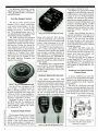
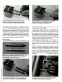
High.Voltage Pulse Generator
-
Add spark power to your experiments!
Laboratory Pulse Generator
Fence Charger Model
Fixing garage -door opener components
Troubleshooting IC's with
a
multimeter
Discover radio through building - blocks
Learning all about static electricity
05
GERNSBACK
o
71
896 4878
8
Plus: Topics on scanners, decibels, DOS, PC
color snapshots, shortwave, voltaic cells,
antique tubes, and more!
-
-_===-_==-=_ =_ _
'=
C
\
P
R
O
R
O
A
T
I
=
L_
/r
O
NATIONAL SEMICONDUCTOR PANASON
OK
AC INC. NJ.W
MCILLERAAVÌDENGNEI
I'
.
AK, Puerto Rico
256K (262,144
^NE'
JOHNSON ATLANTIC SEMICONDUC'
E. F.
INTEGRATED CIRCUeTf
+40r
7/7-800-344-4539/
_
11
4001CMOS
¡
-
'
a.
IIII
.
Ú
WV
..
SO
b)..
..s
.
R
..
.
..
.
.
..
.
.
..i
..
A
D* ,r-
'
'
.
-.
aca
cwos
.rn
.
W MILLERLUxO
ARIES
PLESSEY
__
-
.
°
9103508982 DIGI KEY CORP
%
I
.
.
TW
718 681 3380
150NS $5.1011; $39.95I9+cRCYAG
OSJ.
Factory Firsts
ìC CHEMICALS
._...__...r.....
.
FAX
67877914
x 1) DRAM
,
SOLDER TAIL
DIP SOCKETS
Tele
718 681 6674
...,..__ _._
nwr.n..r.................
*sat
.
.
.
.:
.
12
.
-
WIRE WRAP
..
DIP SOCKETS
-
MO
.v.
.w...ro...re.u..a.n,
re...u....v. -.
..
°...inwi.iy...°.. ...
.
]..
..,r
....s.s.w+w.wrxn.i..i,r
_.
.
4.
..
17w.c.......a.n
v..
...
..-
.
1% Metal
1
.
.........i.
...
e....n
1173 WO FPO
r
LaN
o.
MO
7110
.
$i
m
.0
n
6
7r
=M
,V
...
..
.0
73
7M
1!
ri
w
r.
YaM.
58
25
C7793
FM/ Fied Resistors
.
..
Á
5
It
i
ñ
0701
i1
7
.
,
crtoas
....
'24°'
..
t
l
PANASONIC LS SERIES
A
ao
31
70
'
,..1..
.
,
,
o,
o
®
.m
°¡
.........,....,......
,
.
..
b.
IA
IS
..ww
u....
.
...aw
r.rer
'544:
....
Mein/Wed Pt/Neste, Capnctors
:mT7
;
,., -;;;;;:"
..
ii.n...
rn
vrn
M1iw..
v
i
...
_.
°°c
.
..ic
1.c00 CMO
.
m
.:.
._
.,.
am
1
o
woo
at
.,
-
-
...
®
II,.m
.rww,
1,7,20.,..a,,,
078.
-
U
35
-1.-
.;
i
en
.<v.7w.
i
n
m
.n
7415
.4
n
n
e
.,
.
.
.
r......
.
....,...
1.000
375
` ..
-..
..,..
1000
-L
°
m
m
Y
76
..
trw...
.rv..
.
..
vMW
.m
.
As.
"+
nos
., w
w.a........_....,.
er.d ivwMw
r.b..w
WM
117
..w
CAPACITO.
0T PROOE, CALI
1
900 344 4571
IAM.
gall
Ill 5I111741
ST
NAII 5810 101N
OEOEO 10: 511I1MET. P.O.
IN
077.
TIM Wm NIA NI
61711.
w
w
.
o
0.1 9.99
10.00. 125.00
75.00.841.90
$0.00 -$90.99
.
i7
.
n
,
v
.
a
7d
7
.
ÿ
n u,
T
»
.
n
77
.,.
$3995
'3995
SERVICE CHARGES
0
;
10
4
ñ
CAPACITOMS
010008 Up
CIRCLE 8 ON FREE INFORMATION CARD
v.
p.,,
bra w4aw ewc0um hams that we m. d.caunreN U. 4m1.1ra
,,,.
To Or wetol.l. .dd th n0a d.wenuM dan. Theo .b Ih serrna
A. Canada and Memo when c.d.. money p,w.cca..perr orb, CV Mn onto Woo orb,s,y06n IS c.n.rr,u U S. AMY.
ra r M Ih J.munlö 0mo and got. h» .poraorwt buxom
w ew U S
v i
u
i0
icw..na swviga d.wOw moo.. lo op* Mr hw.w WE by 04 6n aw 6. meAwE
w.ap vow order.
t
a
7
'7:
"'°.
41447
A11w
.r
w.°
016
.
.e...°.............. . ....... ..
1
m
.
-.
_m
.
05 3
000EIg6
SW
$5495
.
M
.
...
OVER
.w n w
u
..... ,....
i,i
11.4.6. Cer..b owl Memo
II.
..:
.
.
dr1P. W py Y d.ppilp
7 53
or`......ae...
v...°c.e.. or
-113
.aw
ww
65
i.wepY.
443
V SERIES
....nw..a.........r.
....
41.N.
Tho OiMM.y.vA.s
-MD 101pbV Pe pan
52
PANASONIC
OS
in
MN
WA
Tv
.
_
107
Al 47
....
C
..n...C......rr....
r1.100.205t 110-¡
.
PI
m
.
.,
3
y.i.n.
.......,....
NEC Memory Chips
17
..,
..
.
I
is
.
co
pay
-
ö
....... ..
-
ww.
II
SO
.
o
Twwrr.V
-
CW
73
....
..
742500
iY:à
SW
VOLUME DISCOUNT
Add 02.00 0 0.013$ 99.99
Add 10.75 $ 100.0130749 99
Add $1.50 $ 750.00 8499 99
Add $0.25 5 500.00- $999 99
Na Charge 110008 Up
NET
Less 10'.
Less 15'+,
Less 2052
less 255,
INCLUDING
10-PAGE
CS
ii
MAY 1988
Volume 5, No. 5
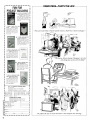
CONSTRUCTION
25
28
39
62
73
-if
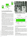
you work block -by -block and section -byThe Building -Block Radio
section, you'll suddenly hear sound from thin air!
The High -Voltage Pulse Generator-build the fence charger or laboratory
models and experiment with lighting, neon, or animal behavior
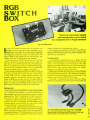
The RGB Switch Box -two computers but one monitor is no problem even
with inversion
Building Voltaic Cells-you've built everything under the sun, but have
you built a battery?
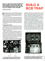
Build a BCB Trap-get rid of noise quick and easy with this simple one
evening project
FEATURES
Building Block Radio-page 25
11111
16
34
Computers- That's the Life -humor from
43
Servicing Garage -Door Openers-Service your garage -door opener and
beyond the cathode -ray tube
Rebuild Your Door Chimes -use these tips to save money and make life
-11111111--'
High Voltage Generator-page 28
more musical
60
64
67
75
77
it'll be around to serve you for many years to come
few artifacts of your hobby can enrich your base
Hamshack Nostalgia
of operations
Checking out Static Electricity -one of the most destructive forces can
be generated and controlled with household items
you have no scope, then you
Troubleshooting IC's With a Multimeter
need this article more than you need clean socks
TAME the DOS Tiger -unleash the power of the machine to do your
-a
-if
The RGB Switch Box -page 39
bidding
E -Z Math -Logarithms number crunching is super easy with logs and
decibels; you may give up multiplication!
SPECIAL COLUMNS
84
86
88
Ellis on Antique Radio -kicking triodes into high gear
Jensen on DX'ing -the Vatican has a lot to say and uses SW to say it
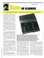
Saxon on Scanners -whip up an instant weather report wherever you are
92
94
Circuit Circus- sequencers revisited; more power, but only a few IC's
Friedman on Computers -hot off the presses: color photos from your PC!
Garage-Door Openers -page 43
on a new Regency release
DEPARTMENTS
2
4
7
17
37
49
71
Editorial -Times Are Changing
Letter Box-free -flying information from readers and staff
hits our pages before it hits the shelf
New Products Showcase
Bookshelf -your safari for information should make camp here
FactCards -our card section packs the down and dirty facts
GIZMO Special Section -written by people who try before you buy
few circles can bring you a world of information
Free Information Card
-it
Hamshack Nostalgia -page 60
-a
Friedman on Computers -page 94
Volume 5, No. 5
The Magazine for the Electronics Activist!
May 1988
Larry Steckler, EHF, CET
Editor-In -Chief & Publisher
Art Kleiman, editorial director
Julian S. Martin, KA2GUN, editor
Robert A. Young, associate editor
Herb Friedman, W2ZLF, associate editor
John J. Yacono, associate editor
Brian C. Fenton, associate editor
Carl Laron, WB2SLR, associate editor
Byron G. Wels, K2AVB, associate editor
M. Harvey Gernsback, contributing editor
Doris Kelly, editorial assistant
Teri Scaduto, editorial assistant
Ruby M. Yee, production director
Times are changing!
Every so often sort out my papers at home, because the filing
cabinet is packed tightly. Sorting through the papers helps me
decide what to throw out and what to keep. I'll admit it is a losing
battle, but it is good to reminisce once in a while.
I
came upon an old speech gave at the Communications
Equipment Distributors Association (CEDA) meeting in St. Louis
on November 5, 1977. At that time the personal computer marketplace was a fledgling compared to the consumer electronics
items being sold through conventional outlets. explained to the
members of CEDA attending the meeting that expected the
marketplace to gross one -billion dollars in 1978. Considering the
sales of Tandy and Zenith during that period along with 30 to 50
emerging hardware and software companies of that time, I'm
sure that passed the mark. prophesied personal computing
products appearing in traditional electronic shops and outlets
across the nation.
I
I
Karen S. Tucker, production manager
I
Robert A.
I
W.
associate
I
Lowndes, editorial
Marcella Amoroso, production assistant
Jacqueline P. Cheeseboro, circulation director
Arline R. Fishman, advertising director
I
So much for forecasting the future. Today checked the Sunday
newspaper and was amazed at the number of local independent
computer outlets and stores selling complete computer systems
to the general public. Computers have entered our everyday life.
Not only at work, but at home and school. Who would send a
child off to college without a basic computer system with word processing software? In fact, high school students look to Christmas and birthdays hoping that that would be the day when they
got their first computer system.
I
What's my point? Electronics hobbyists have been shunning
computer projects and leaving them to the hacker and vice versa
It's about time both groups realize that the computer itself is a
tool that will help them in almost any aspect of their technical
hobby as well as their every -day life. Junk your electric typewriters, dictionaries, and even my filing cabinet. I've got 60 -megs
of memory home, and some of it is for storing what's on my old
papers. Anybody interested in a slightly used four -drawer filing
cabinet?
.
Times are changing.
BUSINESS AND EDITORIAL OFFICES
Gernsback Publications. Inc.
500 -B Bi -County Boulevard
Farmingdale, NY 11735.
516 293 -3000
President: Larry Steckler
Vice -president: Cathy Steckler
NATIONAL ADVERTISING SALES
(For Advertising Inquiries Only)
Joe Shere MIDWEST PACIFIC
1507 Bonnie Doone Terrace
Corona Del Mar, CA 92625
714;760 -8697
The Pattis Group
310 Madison Ave. Suite 1804
New York, NY 10017
212- 953-2121
Cover photo by
N,rh Friedman
Composition by
Mates
/1'
h
®
Hands -on Electronics, (ISSN 0743
' ubkshed m..
Gernsback Publications. inc 500-B B ,.,,nty Boulevar,
ingdaie. NY 11735 Secorid.Class postage paid at Farming,:
and al additional mailing offices One-year. twelve issues. ,...
bon rate U.S and possessions S28 00. Canada S33 00..1.
countries S35 50 Subscription orders payable in U S funds tin ,
International Postal Money Order or check drawn on a U S bank
U S single copy price $2 50
1988 by Gernsback Publications
Inc. All rights reserved Trademark registered in U S and Canad,i
Printed in U 5 A
'
,
.
Postmaster' Please send address changes to Hands-On ElecPO BON 338. Mount Morns. It
tronics, Subscription Dept
61054-9932
stamped sell-addressed envelope must accompany all submitted
manuscnpts and or artwork or photographs rf their return is desired
should they be rejected we disclaim any responsibility for the 'os-,
Of damage of manuscripts and or artwork or photographs while r
our possession or otherwise
A
Julian S. Martin, KA2GUN
Editor
As a service to readers Hands-on Electronics publishes avadahl,
plans or information relating to newsworthy products. technique,,
And scientific and technological developments Because of posse
variances in the quality and condition of materials and work
utshm used by readers. Hands -on Electronics disclaims an.
aionsibilny for the sale and propry i
, 0
eels based upon or from pians o, '
.
.
.lane
2
'
,.
. ,
,
'
,
1
,
,
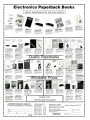
SELECT 5 BOOKS
TROUBLESHOOTING AN
REPAIRING THE NEw
PER
1::4M
for only $3.95
(values to $123.75)
and get a Free Gift!
2660P
517.9!
2617
S17 95
55
BEGINNER'S
EASY TO BUILD
1V f21P!l
ELECTRONIC
PROJECTS
2809 $26.95
Count as 2
1897P
1999P
513.95
ELECTRONIC
I°
522.95
1962
-
1625P
514.95
514.95
Electronics projects ... ideas ... the latest technology
all at up to 50% off publishers' prices!
Membership
2645P
510.95
Benefits Big Savings. In addition to this introductory
offer, you keep saving substantially with members' prices of up to 50% off the
publishers' prices. Bonus Books. Starting immediately, you will be eligible for
our Bonus Book Plan, with savings of up to 80% off publishers' prices.
Club
News Bulletins. 14 times per year you will receive the Book Club News, describing all the current selections- mains, alternates, extras -plus bonus offers and
special sales, with hundreds of titles to choose from.
Automatic Order. If you
want the Main Selection, do nothing and it will be sent to you automatically. If
you prefer another selection, or no book at all, simply indicate your choice on the
reply form provided. As a member, you agree to purchase at least 3 books within
the next 12 months and may resign at any time thereafter.
Ironclad No -Risk
Guarantee. If not satisfied with your books, return them within 10 days without
obligation!
Exceptional Quality. All books are quality publishers' editions
especially selected by our Editorial Board.
All hooks are hardcover unless numbers are followed by a
1536P
58.95
p'--_
2887
516.95
"P"
518.95
THE MASTER
HANDBOOK OF
IC CIRCUITS
yytrwa
~11/110.11
nf
SE MOWER S. POWERS
ta1
Ì%=
s`'::ll1
Handy, Pocket -Sized
EL
Counts as
1775P
524.95
FREE when you join!
Color Code Calculator
524.95
2922
for paperback (Publishers' Prices Shown)
Resistor and Inductor
1300P
BASIC
ELECTRONICS
a
2733
2960 524.95
514.95
2613
ri
I11
r:r'. ti I.Irrl,i
IF
ELECTfiONJCS BOOM CHUB
523.95
2
1218P
514.95
Blue Ridge Summit, PA 17294 -0810
Please accept my membership in the Electronics Book Club' and send the 5 volumes listed
below. plus my FREE Resistor and Inductor Color Code Calculator (502E). billing me $3.95
plus shipping and handling charges. If not sa isfied. may return the books within ten days
without obligation and have my membership canceled. agree to purchase at least 3 books
at regular Club prices (plus shipping and hand! ng) during the next 12 months and may resign
any time thereafter
-
2941
p
521.95
-
111115
I
MASTER
I
2758
$24.95
1604
A.\
2790
516.95
IC
COOKBOOK
518.95
1199P
514.95
2731
514.95
Name
Address
City
State /Zip
Phone
Signature
Valid for new members only Foreign applicants will receive special ordering instructions Canada
must remit in U.S currency This order subject to acceptance by the Electronics Book Clnb
.Signature of parent or guardian required for all new members under 18 years or age
RESP -588
2839
515.95
2753P
1532P
516.95
CIRCLE 14 ON FREE INFORMATION CARD
521.95
LJLJ
DD
3
Hands -on Electronics, 50OB Bi- County Boulevard, Farmingdale, New York 11735
High Capacity
would like to congratulate you on a
first class publication. It certainly meets
the need of the hands -on hobbyist. The
projects are great and very educational.
Perhaps you would consider doing an
article or a series of articles on the use of
capacitors in DC circuits. When capacitors are used in AC circuits there seems
to be plenty of information around on
how to calculate the required value but
when it comes to DC I can find nothing.
A case in point was a Wheatstone
bridge circuit (a fairly recent project)
used to detect continuity on any line with
under 10 ohms resistance. The output
from the circuit fed an op amp which
activated a buzzer when an imbalance
was detected. The device is intended for
circuit tracing and is set to ignore values
greater than 10 ohms. On the output line
from the bridge to the op amp there is a
0.27 -µF capacitor providing a path to
ground. I assumed it was to stop spikes
from the detection circuit. When I built
the circuit the capacitor looked too big,
but had no basis for calculating anything to resolve the question in my mind.
Can you do anything like that?
-J.H., Garden Grove, CA
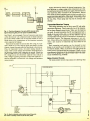
I
with a mechanical switch without debouncing and no diagram should ever
be shown (particularly when it's aimed at
the novice because it "appears" simple)
that forgets to include this important parameter.
have two suggestions that feel certain will resolve J.W.'s problem. First
throw out that stone -age 555 and replace it with the CMOS version (Radio
Shack No. 276 -1718). In addition to low
power consumption the CMOS noise immunity while not perfect, is vastly better
than the other logic families.
Second there are countless debouncing circuits, both simple and complex.
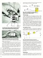
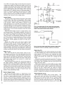
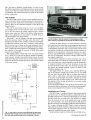
The circuit in Fig. 1 is a very simple one
using a 4584 Hex Schmitt Trigger. When
I
turered it, has gone out of business. Anyway, wrote to them and never received
an answer. Any help you can give me will
be greatfully appreciated. William L.
Heaton
P.O. Box 786
Weaver, AL 36277
I
+VDD
I
I
Would any of our readers drop a note
to William should they be able to assist?
More Numbers
Did you publish an article about six to
ten months ago on a Centronics parallel
printer port for the Timex /Sinclair 1000
computer? Please include the volume
and issue number if applicable.
-W.W., Honolulu. HI
A miss is as near as a mile in electronics. The story we ran in November
1986 was for the Sinclair ZX -81. There
may be some similarities in the machines. but I wouldn't swear to the 1000s
compatibility with the project we showed
in the article.
I
A general article on the subject of capacitance had been presented in the
June 1987 issue. It would be a little difficult to publish articles that went into detail on parts substitution (and there are
many readers who just wouldn't like
them). I strongly suggest you check the
public library nearest you if the article
provides insufficient help.
Alarming Letter
In reference to the letter from J.W. of
Ashland. AL, entitled "Washed Out" in
the February 1988 edition of Hands -On
Electronics, say fine, go ahead and
house your alarm in a metal box along
with shielded cable, as the response to
his letter suggests. Shielding the circuit
will reduce false triggering, but if you
look at the schematic (page 63, Jan./
Feb. 1986 the solution to J.W.'s problem
is to debounce that mechanical key
switch. No counter, timer. inverter, buffer,
etc., can function properly in a circuit
I
High and Dangerous
Where can pick up a neon lamp high voltage transformer for a project am
working on?
-B.M., Dayont, OH
I
I
the switch is closed the RC time constant determines how long the input to
the inverter is held high. The reset pin
(pin 4) is held momentarily low preventing the chattering of the switch contacts
from prematurely triggering the timer.
-D.K., Willingbord, NJ
You are of course quite right. If the
problem is more than just false triggering
(indicated by the units triggering for no
good reason) then debouncing will solve
the other problems. We proposed a solution to the one problem that definitely
existed hoping it would be enough.
Scan This!
Help! am unable to find any information on how to obtain a service manual
for my Bearcat 150 scanner. (Please
don't tell me to throw it out.) Howard
Sams does not list it, and have heard
that Electra, the company that manufacI
I
Most neon lamp high- voltage transformers are rated at 7300-volts AC at 5 mA.
That's enough soup to kill. Whatever you
do, do it carefully, and place warning
signs near the project so that others will
stay clear. American Design Components, 62 Joseph Street, Moonachie, NJ
07074 sells such a unit for $9.95. Understand that this is a limited supply of surplus units. so order today! In a rush? Call
them at 800 524 -0809. Tell them
Hands -on Electronics sent you.
Tune up
I'm writing you about the Hour Tune
project in the June 1987 issue. After
comparing the information that came
with the Melody Generator UM3482A,
the schematic on page 34, circuit layout
on page 35. and parts layout on page 36,
noticed a discrepency. I don't know if it
I
.. ....w r.;.
HEADPHONE
THYRISTORS
INTERFACE
POLARITY
TF`'Tr^
-
YOU CAN HAVE THE NEXT TWELVE ISSUES of Hands -on Electronics delivered to
saving $11.05 off
your home for only $18.95
the single copy price.
-
`
i
_7
'
i..'el
IF YOU'RE THE KIND OF READER that
doesn't want to wait, you can order your next
copy of Hands -on Electronics now. Hands -on
Electronics is crammed full of electronic projects that you won't be able to wait to build for
yourself. You can expect top-notch digital projects, fun -to -play electronic games, valuable
add -on computer projects, BCB and shortwave
receivers, photographic /darkroom gadgets, devices to improve your car's performance, test
equipment ideas, and more in every issue of
Hands -on Electronics.
EVERY ISSUE OF Hands -on Electronics
will continue to contain a variety of construction
articles to suit every taste. In addition, feature
articles on electronics fundamentals, test equipment and tools will round out each issue. Of
course. Hands -on Electronics will continue to
provide new product and literature listings to
keep you up to date on the latest developments
in electronic technology.
GET IN ON THE ACTION! Order your next
issue of Hands -on Electronics today. Use the
convenient order coupon below. Be sure to send
check or money order -no cash!
i
Hands -on Electronics SUBSCRIPTION
want to be sure don't miss any issues. Send me ONE FULL YEAR
Hands -on Electronics for $18.95 (Canada $23.95 U.S. Funds).
I
I
r]
[
Payment Enclosed
] Bill Me
Later
Please charge my
Visa
D Mastercard
-
twelve issues
-
of
Signature
Exp. Date
Acct #
Allow 6 -8 weeks for the first issue to arrive. Offer valid in U.S. Funds Only.
Detach and mail today
Please print
to:
HANDS -ON
ELECTRONICS
SUBSCRIPTION DEPT.
P.O. BOX 338
MOUNT MORRIS, IL
61054
(Name)
(Stmet Address)
(City)
(State)
(Zip)
AHOE8
was to test the readers or just an error.
But Cl and R3 are not included in Fig. 1
and a connection between pin 16 on U2
(UM2483A) and Vcc at B1 (+ side) at pin
9 on U2 is also missing. have enclosed
a new schematic with all the corrections
drawn in and highlighted. hope this will
help whoever builds the project.
Also, had a problem with a low audio
output at SPKR1. No matter how adjusted R6 and /or R7, I would still only get
I
books on electronics is between these
pages. You'll find quit a variety of technical books in our The Bookshelf column
and among the advertising every month.
(Read those ads! They are informative
and reduce a lot of leg work.)
I
I
I
very -low audio output. found connecting pins 9 and 10 on the Melody
Generator together brought the sound
I
up to full level. The only problem is that
that causes a small amount of feedback
and audio distortion, but not enough to
bother you if you're not listening for it,
and if R6 and R7 are adjusted properly.
would like to know if anyone else had
that problem, and if so, what did they do
to correct it.
-C.E.F., Titusville, FL
I
Thanks, its not easy keeping track of
all the parts for a project of that size.
While we can't print the schematic here,
the additions are as follows:
Connect Cl to the ground and pin 16 of
U2.
Connect R3 between pin 12 of U2 and
pin 4 of U4.
Connect pin 16 of Ul to B1 on the
positive side.
We haven't heard from anyone with
the audio problem you describe. If you're
out there, write in about it.
Tuned Out
read Electronic Fundamentals by
Louis E. Frenzel Jr. in Hands -on Electronics March 1987 issue, and don't
understand somthing on page 80. can't
figure out the math used to find the resonant frequency in step 8. It reads:
I
I
I
or .0000001F
6.28) %(2 x .0000001)
f = (1 6.28); .0000002
f = 1 6.28(.000447)
C =
f
I
-
.11.1.F
(1
don't know where you get the
.000447. I'm just a beginner in the field.
Please help me.
Also, could you please tell me where
can find some books on electronics formulas? sure would appreciate it very
much.
-T.B., Portage, WI
I
You'll be happy to know you've made a
bright start in this field! The error is not
yours but ours. after the third line it
should read:
f = 1 (6.28 \ .0000002)
f - 1 (.000001256)
f = 796178.35 Hz
The best place I can think of to find
Variety: the Spice of Life
When was building the "Rip-Off Retarder Alarm" that appeared in the July
'87 issue of Hands -on Electronics,
found an error in the foil pattern that was
provided to make the PC board. The
positive end of C8 should be connected
to the junction of R1, R2, and D5 in order
for the relay to get its current. The schematic diagram was correct, but the foil
pattern wasn't.
Also, am having a terrible time finding C3, a 10-160 pF trimmer capacitor.
Could you please tell me where I can find
one?
I
I
I
-H.V.,
Mt. Airy, NC
Sorry to say we had trouble getting
them too. Try getting somthing more
common such as a 6 to 50pF and double
them up if 50 pF isn't enough.
Feet On the Ground
Here is a response to the letter on
Grandpa's Radio on page 31 in the October issue on shorting out the battery.
That letter is found in the Letter Box of
the February 1988 issue.
Resistor R4 is the regeneration control. Regeneration takes place towards
the high end of the control at the drain
terminal of 02. That control is hardly
moved at all after regeneration takes
place. Remember the little radio pulls
only 9.6 mills under working conditions.
In event R4 would get lowered towards
ground and left there, place a 4.7K ohm
resistor between the ground terminal of
R4 and common ground, to provide battery protection.
-Homer L. Davidson
It can be assumed that the potentiometer should be adjusted to its highest
resistance before power is applied, for
those who do not wish to add the safety
resistor Thank you for your reply.
Errors? What Errors?
This is my first year to subscribe to
your magazine and from what I have
been seeing, reading, and putting together it will not be my last.
There is one thing do have to ask you.
About the problems that have found
and read in your Letter Box section, are
they real goofs or are they there to teach
lessons to those that are smart enough
to catch them?
-J.R., Highland, IL
planned: mistakes, the letters themselves (including your's), and so on, are
bonafide. Yes, we produce real mistakes, do not be fooled by imitations. We
would never purposefully mislead our
readers (except perhaps in April) for any
reason.
Our educational value lies not in our
errors, but in our dedication to our own
hobby. I don't mean to make little of our
errors, but pick up our magazine and
compare the number of construction
projects we put out to that of any other
publication of our kind. Skip the columns
and just concentrate on the projects
alone. You'll find more in our magazine
for sure. Now add on the number of columns that also contain buildable circuits
such as Circuit Circus, and you'll get an
idea of how many schematics their are in
one issue. Being human (as some editors hate to admit) mistakes are bound to
sneak by in the flood of information we
wade through.
When all is said and done, we really
appreciate the readers who carefully
read the articles and inform us of any
discrepancies. They have really helped
the magazine (and this column) become
the source of useful information that it is.
Death to Computers
In the February 1988 issue you said
you wanted complaints as well as praise.
Well, your response to the request to
"Stay low on computer stuff" was "Not to
worry," that we would not see "How to
Build a Clone from the Gates Up;" that's
fine, but see a gradual creep of more
and more computer software articles.
I
After seeing one popular electronic
magazine go that way get nervous
I
when 15% of the best magazine for the
electronics activist is dedicated to computer- related stuff. Please don't turn our
great magazine into Hands -Off Electronics.
-W.E.H., Huntsville, AL
Again, I must quell your fears. This
magazine does software reviews that
are brief and do not compose 15% of the
magazine. Perhaps 15% if you count the
items on the contents page; but how
many pages are dedicated to software?
Also, consider the scope of such articles. They can't be called hardcore, they
simply expound on the features of each
package.
Sit -Down Walkman
I
I
While I could tell you that everything is
am interested in connecting a Walkman -type tape player to my stereo
system. I realize that there is a substantial difference in the output of such a unit
vs. that of a tape deck. What type of
matching circuit can you suggest?
Would the installation of a pair of small,
(Continued on page 103)
I
Famous
rJ_D-EPUr
A very special
guide to what
the exciting world
of computer and
electronics kit building can
do for you.
Cassette Care Tote
The K -1000 is the only carry bag
for pull -out cassette receivers that features a full cleaning and demagnetizing kit, built into the bag. The K1000 Carry Bag & Cassette Care Kit
consists of Intraclean's proprietary C911 Cassette Cleaner, a D -501 Electronic Cassette Demagnetizer, and a
The informative Heathkit Catalog shows
you more than 450 exciting electronic products that will challenge, instruct, and entertain you. You'll find countless kits that you
can build and enjoy, from computers and
robots to color
tv's and a variety of
home products.
And each is backed
by our years of
experience and
our promise,
won't let
y
`41Fyou fail:'
CIRCLE 73 ON FREE INFORMATION CARD
servicing requirements for UHF radio
communication systems and cellular
UHF phone radio links. Suggested resale price is $475.00.
For complete details and specifications, contact your electronics distributor or Mercer Electronics, 859 Dundee
Avenue, Elgin, IL 60120 -3090; Tel. 312/
697 -2260.
CIRCLE 93 ON FREE INFORMATION CARD
nylon carry bag design to fit any pullout cassette receiver.
Suggested retail for the K -1000 is
$59.95. For more information contact
American Recorder Technologies, Inc.,
PO Box 3592, 4505 -2H Industrial Street,
Simi Valley, CA 93063; Tel. 805/527-
9580.
Multifunction Frequency Counters
The Model 9810 Frequency Counter
and the Model 9800 Frequency Counter
provide period -measurement, period average and totalize functions. Both feature a large, eight -digit LED display
with anunciators. All inputs and functions are front -panel mounted and clearly
marked for ease of use.
The Mercer 9800 counter, with a 10Hz range, is ideally suited for general
purpose service, lab use, education,
audio test, digital and hobby applications. Its period, totalize the period average functions make it a value -priced
instrument for production applications
as well. Suggested resale price is
$255.00.
The Mercer Model 9810 counter provides an extended range -10 Hz to
GHz-to satisfy the product testing and
1
,/
IBM-PC
Compatible Expandable
Computers
HERO
AM /FM 5 -Band Graphic -Equalizer
Stereo
The Sparkomatic SR38 AM /FM Stereo Radio Cassette Player features easyto -use slide controls for its 5 -band
graphic equalizer, which is designed to
shape the sound to the car's environment
and listener's preference.
The radio incorporates a locking fast forward button and pushbutton eject and
s,s,
1
Precision
Test
Instruments
Electronic
Keyless
Doorlock
sound balance. Other mode controls are
non/stereo, AM/FM selectors and a local distance switch.
'I MhI'1,..VI1Iwl'
il
MI
11
111
11
11
s
.
balance/fader control which adjusts
B
2000
Educational
Robot and
Courseware
®
PackKit Multi -Mode TNC
Ö
CIRCLE 83 ON FREE INFORMATION CARD
The Sparkomatic SR38 also features
indicator lights that tell the driver when
the unit is in the tape or radio mode or
in mono or stereo. Full night lighting
illuminates the unit's functions, making them visible to the night driver.
Specifications for the Sparkomatic
SR38 are: 12 Watts (O 10% (RMS) THD/
10 Watts dal 1% (RMS) THD. Suggested
retail price is $79.99.
r
Send NOW fort
7
your FREE
Heathkit Catalog.
Send to: Heath Company, Dept. 107.652
Benton Harbor, Michigan 49022
Name
Address
State
subsidiary o1 Zenith Electronics Corporation
C ty
A
Zip
CL -784R3
Heathkie
Company
CIRCLE
11
ON FREE INFORMATION CARD
7
For additional information, contact
Sparkomatic Corporation, Milford, PA
18337; Tel. 800/233 -8831. In Pennsylvania 800/592 -8891.
Two -Way Speaker System
The ALS -52 2 -Way Speaker System
features a 51 /4 -in. woven, carbon -fiber
cone woofer incorporating a -in. flat ribbon wire voice coil with double
damper and a 8.65 oz. strontium magnet. The midrange /tweeter uses a 14mm polyimide dome with magnetic fluid
for damping and heat dissipation.
The Altec Lansing door -mounted
speaker system has been engineered to
withstand the extremely high and low
temperatures usually found in automobile interiors. Further, the system has
been designed to provide the wide dynamic range and fast, accurate transient
response needed for optimum music reproduction of Compact Discs, high quality cassettes, and stereo broadcasts.
The system may be installed in most
late model American, European, and
Japanese automobiles.
1
CIRCLE 85 ON FREE INFORMATION CARD
system will switch off. Thus, the user
is able to immediately start conversing
without having to first turn off the sound
system. Upon termination of the call,
the system resumes normal operation.
The ARSO5 is small in physical size,
easy to install, and requires only five
connection points. Because the ARS05
uses electronic switching, reliability is
high, and there is no additional power
consumption by the unit. Adjustable sensitivity control enables the unit to be
used with virtually any cellular telephone
on the market.
The ARS05 carries a suggested retail
price of $49.95. For more information,
contact ORA Electronics, 20120 Plummer Street, Chatsworth, CA 91311; Tel.
818/701 -5848.
Modulink Mobile Microphones
CIRCLE 77 ON FREE INFORMATION CARD
The ALS -52 has a frequency of 80
Hz to 22 KHz + / -3 dB and sensitivity
(SPL) of 90 dB /watt/meter. At watt
the THD is 0.8% Hz over a range from
150 Hz to 22 KHz. Power- handling capacity is 30 watts nominal and 60 watts
maximum. Impedance is 4 ohms.
Suggested list price for the ALS -52
is $160.00 per pair. For additional information contact Altec Lansing Consumer Products, Milford, PA 18337:
Tel. 800 /ALTEC 88.
1
The Model 890TT and 590T
ModuLink Systems are two mobile communication microphones that feature a
unique modular-cordset which enables
each microphone to plug into over 40
radio models in just 30 seconds. The
cord can be released quickly and easily, but a locking -action tab prevents
inadvertent release
miniature screwdriver must be inserted into a rear-
-a
access port to release the cord.
The 890TT uses sophisticated CMOS
integrated-circuit technology to provide
DTMF dialing. It also features memory
storage of up to ten 16 -digit telephone
numbers, has automatic last- numberdialed memory storage, audible tone confirmation, selectable dialing speed, and
automatic transmitter keying. Another
key feature of the 890TT is that it illuminates from the microphone line, eliminating the need for a separate 12 -volt
power line.
Further, they eliminate the need to
open the microphone or the radio to set
radio deviation levels. With ModuLink
System 1, you can easily and quickly
set levels through a rear access port.
Accidental readjustment is prevented be-
cause a miniature screwdriver is needed
to make the setting.
Both 890TT and 5901 models feature a million cycle plus leaf switch and
an Armo-Dur case that's immune to oil,
grease, most fumes and solvents, salt
spray, sun, rust, and corrosion.
The pricing of the units is: $208.25
for the Model 890TT; and $47.00 for
the Model 590T They're available from
Shure Brothers Inc., 222 Hartrey Avenue, Evanston, IL 60202-3696; Tel. 312/
866 -2527.
Soldering Iron Stand Collects
Excess Dross
A sturdy, soldering iron stand that
features a coil spring holder and a thick
sponge for tip wiping and dross collection is available from M.M. Newman
Corporation.
The Antex ST-4 Soldering Iron Stand
features a noncharring plastic base with
a coil spring holder that dissipates heat
to prolong tip life and includes a 1/2 inch
thick sponge for tip wiping, along with
(Continued on page 12)
Automatic Radio Switch
The Automatic Radio Switch, Model
ARSO5, hooks up to both the cellular
telephone in a car and the car's sound
system. If the sound system operates
and the cellular phone is ringing, or if
an outgoing call is attempted, the sound
8
CIRCLE 71 ON FREE INFORMATION CARD
"Harry used his computer software to
write his will. Now some hacker
inherited his money!"
can even earn your Associate in
Applied Science Degree in Electronics Engineering Technology. Of
course, you set your own pace, and,
if you ever have questions or
problems, our instructors are only
a toll-free
phone call away.
first step
eyours.
s.
To find out more, mail in the
coupon below. Or, if you prefer,
call toll-free 1-800-321-2155
(in Ohio, 1-800-523-9109).
We'll send you a copy of CIE's
school catalog and a complete
package of enrollment information.
For your convenience, we'll try to
have a representative contact you
CIE MAKES THE WORLD
OF ELECTRONICS YOURS.
Today's world is the world of electronics. But to be a part of it, you
need the right kind of training, the
kind you get from CIE, the kind that
can take you to a fast growing career
in business, medicine, science,
government, aerospace,
communications, and more.
Secialized
training.
You learn best from a specialist,
and that's CIE. We're the leader
in teaching electronics through
independent study, we teach only
electronics and we've been doing
it for over 50 years. You can put
that experience to work for you
just like more than 25,000 CIE
students are currently doing
all around the world.
actical
training.
to answer your questions.
4K RAM Microprocessor Training
Laboratory, for example, trains you to
work with a broad range of computers in a way that working with a
single, stock computer simply can't.
Prsonalized
raining
You learn best with flexible
training, so we let you choose from
a broad range of courses. You start
with what you know, a little or a
lot, and you go wherever you want,
as far as you want. With CIE, you
CIE
AHO-81
Cleveland Institute of Electronics
1776 East 17th
St., Cleveland, Ohio 44114
YES! I want to get started. Send me my CIE school catalog including details about
the Associate Degree Program. I am most interested in:
television/high fidelity service
computer repair
medical electronics
telecommunications
broadcast engineering
robotics /automation
other
Print Name
You learn best with practical training,
so CIE's Auto-Programmed® lessons
are designed to take you step-by -step,
principle-by- principle You also get
valuable hands-on experience at every
stage with sophisticated electronics
tools CIE -designed for teaching. Our
Apt.
Address
City
Age
State
Zip
Area Code/Phone No.
Check box for G.I. Bulletin on Educational Benefits
Veteran
Active Duty
CIRCLE 9 ON FREE INFORMATION CARD
MAIL TODAY!
ELECTRONIC
COMPONENTS
NEW PRODUCTS
(Continued from page 8)
CATALOG
.
.
.
yours FREE
.
by dialing
1- 800 -992 -9943
In
Texas: 817/ 483 -4422
Call Today for your FREE
subscription to the 1988
Mouser Electronics Catalog.
Contains 176 pages featuring
over 16,000 in- stock, quality
electronic components.
..PLUS..Mouser's proven
service and prompt delivery.
(Outside U.S.A., Send $2.)
MOUSER
ELECTRONICS
2401 Hwy 287 North
Mansfield, Texas 76063
'DISTRIBUTION
CENTERS
NATIONWIDE
CIRCLE 12 ON FREE INFORMATION CARD
CIRCLE 89 ON FREE INFORMATION CARD
a center hole for collecting excess dross.
Designed for use with all miniature
soldering irons, the Antex ST -4 measures 6 x 21 /2 -in. and has four, non -skid,
non -scratch, rubber feet to keep it securely in place.
The Antex ST -4 Soldering Iron Stand
sells for $7.20 (suggested. retail). For
more information contact: M.M. Newman Corporation, PO Box 615, Marblehead, MA 01945; Tel. 617/6317100.
Quiet Power Conditioner
AMAZING
SCIENTIFIC & ELECTRONIC
PRODUCTS
PLANS-Bm10
Yourself -All Parts Available In Stock
LC7- BURNING CUTTING CO, LASER
RUB4- PORTABLE LASER RAY PISTOL
TCC1
S
20 00
20 00
-3 SEPARATE TESLA COIL
20 00
PLANS TO 1 5 MEV
I0G1 -ION RAY GUN
GRA1- GRAVITY GENERATOR
1000
1000
EMU -ELECTRO MAGNET COIL GUN/LAUNCHER
6.00
These Super-Quiet models feature exceptionally low audible noise of only
40 dBA, making them ideal for office
environments or other areas where low
audible noise is a primary consideration.
The Super -Quiet models offer the
KITS
MFTIK
-FM VOICE
TRANSMITTER 3 MI RANGE
VWPM5K- TELEPHONE TRANSMITTER 3 MI RANGE
BTC3K- 250.08 VOLT 1014" SPARK TESLA COIL
LHC2K- SIMULATED MULTICOLOR LASER
BLS1K- 100.000 WATT BLASTER DEFENSE DEVICE
ITM1K- 100.000 VOLT 20' AFFECTIVE
RANGE INTIMIDATOR
PSP4K -TIME VARIANT SHOCK WAVE PISTOL
PTGTK- SPECTACULAR PLASMA
TORNADO GENERATOR
MVPIK SEE IN DARK KIT
49 50
3950
19950
3950
6950
same broad input voltage range and narrow output band of other Escort models. Constant regulation is maintained
within + 3% to -6% of nominal rated
voltage for fluctuations as large as
+ 15% to -35% of nominal. The excep-
tionally fast response time of 16 milliseconds provides critical protection
against voltage sags and brownouts.
In addition, Super-Quiet Escort models provide common -mode noise attenuation at a ratio of two million to one
(126 dB) and normal -mode noise attenuation at a ratio of 1,000 to one (60
dB), virtually eliminating costly noise related problems.
Super-Quiet Escort Power Conditioners are available in convenient line -cord/
receptacle models from 70 VA to 2 kVA.
Prices start at $195. For complete information, contact your nearest Topaz
distributor or Tel. 619/279 -0831.
Communications Surge
Suppressor
The Perma Power Surge- Protected
Outlet Strip, provides four power-line
outlets, one telephone -line input, and
one telephone -line output. It is the first
Perma Power strip unit to combine the
two functions.
Data communications equipment, is
particularly vulnerable to erratic operation from spikes and transients, because
there are two potential ports of entry
for spikes and transients: the telephone
line and the power line. The Perma
power Model RTD410 Communications
Surge Suppressor provides protection
for both lines, including protection from
all three ways that surges can travel on
the power lines -in the normal -mode
and both common -modes.
The Tele-Line surge suppressor circuit employs a three- element gas tube
and three metal -oxide varistors (MOV)
in a coordinated design, to reduce the
6950
5950
149.5U
199 50
ASSEMBLED
PG70H- MULTICOLORED VARIABLE
MODE PLASMA GLOBE
BTC10 -50.00 VOLT- WORLD'S SMALLEST
199 50
44.50
TESLA COIL
LGU40-1MW HeNe VISIBLE RED LASER GUN
TAT20 AUTO TELEPHONE RECORDING DEVICE
199 50
-SEE IN TOTAL DARKNESS
LIST10- SNOOPER PHONE INFINITY
349 50
169 50
GPV10
IR VIEWER
TRANSMITTER
-
24 50
IPG7O- INVISIBLE PAIN FIELD GENERATOR
MULTI MODE
74.50
CATALOG CONTAINING DESCRIPTIONS OF ABOVE PLUS
HUNDREDS MORE AVAILABLE FOR S1 00 OR INCLUDED FREE
WITH ALL ABOVE ORDERS
PLEASE INCLUDE S3 00 PH ON ALL KITS AND PRODUCTS
PLANS ARE POSTAGE PAID SEND CHECK. MO VISA. MC IN
US FUNDS
INFORMATION UNLIMITED
P.O. BOX
12
716 DEPT
AMHERST. NH 03031
CIRCLE 81 ON FREE INFORMATION CARD
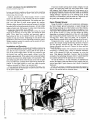
"Herb and I couldn't possibly correct the
overheating problem 'till after lunch."
Do You Suffer
From...
CIRCLE 65 ON FREE INFORMATION CARD
transient surge energy to a safe value. Most carbon -block
surge arresters were designed forelectromagnetic telephones,
and are not adequate for protecting electronic equipment.
The Perma Power Communications Surge Suppressor also
offers the particular protection of failsafe automatic shutdown. If the power-line surge suppressor element wears out
or burns out from handling large or repetitive surges, a patented circuit disconnects the equipment from the power line
so that computers. modems, or other equipment are never
exposed to raw, unprotected power. A neon light turns off
to indicate that automatic shutdown has occurred. Other surge
suppressors may burn out without providing any indication
they have done so. thus allowing equipment to operate unprotected.
The unit offers the convenience of a master on/off switch
with indicator light. A six -foot, double -insulated, power line cord (#14/3 SJT) and mounting bracket with screws
allow convenient placement. A seven -foot telephone -line
jumper cord is included for connection to the telephone line
Manufacturers suggested user price is $72.60.
Perma Power products are available from electronic, computer and office supply outlets nationwide. Free literature
is available from Perma Power Electronics, Inc., 5601 West
Howard, Chicago. IL 60648; Tel. 312/647 -9414.
High Prices
H Limited
\
Selection
Slow Delivers'
Unfriendly L.,
Service
All of the above
]
J)
MCM
Electronics
Brings
Phone Aid
Have you ever had a conversation over the telephone with
an elderly person or someone suffering from hearing loss
and had to talk louder so they could effectively hear you?
The clever slip -on amplifier makes voices sound louder
and clearer. It comes with an adjustable volume control and
fits an standard tele home receiver. It measures 21/2 in
CIRCLE 75 ON FREE INFORMATION CARD
battery
:
and operates on a ul,_le
\ \..
(not in
diameter
eluded). Will make a thoughtful gift for anyone with a
hearing problem.
It costs $9.95 plus $1.00 S &H. NC residents add 50 cents.
Contact BRT Enterprises. 211 Meadowview Drive, Suite
428, Boone. NC 28608
CB Preamplifier
Dubbed RFTR Signal Intensifier this amplifier is specifically configured to improve the coverage of citizens -band transceivers by amplifying the received signals to improve reception. The FCC limits transmitter power, not the receiver sensitivity. By making the receiver more sensitive with an RFTR
.
Relief!
If you're tired of all the "headaches" that come from
dealing with an electronics supplier that doesn't seem
to understand your needs, it's time to pick up your
phone and ask for a FREE copy of MCM's new catalog!
This 168 -page "powerhouse" of electronic parts and
components offers some of the best values in the
industry on nearly 10,000 of the most commonly
requested items.
You'll appreciate the friendly, personalized service
provided by our courteous Sales Representatives and
some of the most flexible payment terms in the industry.
And you'll be pleased to learn that thanks to our huge
inventory and state-of- the-art order entry system, your
products can usually be on their way to you in 24
hours! So, get your copy today and get the relief you've
been looking for. You won't be disappointed!
For your FREE copy,
call TOLL -FREE!
1- 800 -543 -4330
In
In Ohio, call 1- 800 -762 -4315
Alaska or Hawaii, call 1- 800 -858 -1849
MCM ELECTRONICS
PARK DR.
85B
E. CONGRESS
CENTERVILLE. OH 45459
A PREMIFR Company
SOURCE NO. HO -14
CIRCLE 10 ON FREE INFORMATION CARD
13
TV, RADIO
NEW PRODUCTS
COMMUNICATIONS
4
BP91 -INTRO TO RADIO DXING
$5.00. Everything you need to know
about radio DXing and how
you can get into this fascinating hobby area.
....
Technics Power Amplifier
Loge $t.Bsaa
Outdo
BP155 -INTL RADIO
STATIONS GUIDE
CIRCLE 91 ON FREE INFORMATION CARD
...
56.95. New edition lists station site. country, frequency.
ERP provides for thousands of short wave radio
cover a variety of broadcast
services.
BP105- ANTENNA
....
PROJECTS
$5.00.
Practical antenna designs
including active, loop. and
ferrite types that are simple
and inexpensive to build,
yet perform well. Also included are antenna accessories.
25 Simple
BP125- SIMPLE AMA-
Amateur Band
Or
Acnalx
TEUR BAND ANTENNAS
.. 55.00. Shows how to
build 25 antennas starting
with a simple dipole and
working on up to beam, tri-
angle and even a mini
rhombic.
)5 S....We
s....a..at
aMnr.w
BP132
Sand
....,.
-25 SHORT-
WAVE BROADCAST ANTENNAS.... $5.00. Good
antennas can be inexpensive. Here's 25 different
ones ranging from a simple
dipole, through helical designs to a mu-band um
brella.
BP136 -25 INDOOR
AND WINDOW ANTENNAS
$5.00. If you
25 S.mpio Indos,
and Window
Lanais
....
can't put up a conventional
antenna because of where
you live. one of these 25 designs is likely to solve your
problem and deliver great
reception.
MAIL
P.O.
TO
will appear as if all your friends were
running illegal 100 watters.
The RFTR simply installs in the antenna.lead of any (AM or SSB) CB transceiver and connects to the units 12 -volt
power supply. Received signals are increased a minimum of 13 db. By means
of an internal relay, the preamp is autoit
stations. Nine sections
Burnisher and direct -reading Micro rulers. Also shown are Micro -lapping
kits, Zirconium ceramic scissors and
ceramic -tipped tweezers.
Free folder includes technical data
as well as prices and ordering information. Contact Minitool, Inc., 1334/F
Dell Avenue, Campbell, CA 95008;
Tel. 408/374 -1585.
matically bypassed when transmitting.
Insertion loss and VSWR are negligible
and the unit draws only 80 ma at 10 -15
volts DC.
RFTR Signal Intensifiers are available for $49.95. To order or for additional information contact the Sales
Department, Electron Processing, Inc.;
Tel. 516/764 -9798.
Technics has four car -audio amplifiers with the top -of- the -line model, the
CY-M400, offering tri -mode operation
with a maximum total -power output of
400 Watts (200 x 2, 200+ 100 x 2, or
100 x 4 bridgeable max). The CYM400 has been designed for varied
applications, including multiple amps.
The three other models include the
CY-M200 (100 Watts /channel max), and
the CY -M50 (25 Watts/channel max.)
All four units offer DIN //RCA dual
input to mate with all Technics head
units as well with head units from many
competitors. The CY -M400 has a 5mm DIN cord to facilitate trunk mounting while the other three units come
with a 1.5 -mm DIN cord.
Precision Tools Pamphlet
A free folder is available from Mini tool Inc. showing the company's line
of precision miniature hand tools for
laboratory and production tasks, as well
as for fine assembly work, delicate
deburring jobs, and printed circuit artwork and repair. Shown are Minitool
sets with hardened tool steel and Carbide tips, Technician sets, Minitool
kits, Diamond scribers, Electrical microtest probes with interchangeable probe
handles, Micro test probes with integrated handles and audible beepers,
unique Precision pin vises, Sapphire
CIRCLE 87 ON FREE INFORMATION CARD
An input -level adjustment for each
unit allows the listener to fine -tune amplifier response to the car speaker's
sensitivity. Adjustments are made by
tuning the control via a recessed screw
on the front panel.
Frequency response for the CY-
Electronic Technology Today Inc.
Box 240
Massapequa Park. NY 11762 -0240
SHIPPING CHARGES
$1.00
$0.01 to $5.00..
$5.01 to $10.00 ...$1.75
$10.01 to 20.00... $2.75
$20.01 to 30.00...$3.75
Z
IN USA 8 CANADA
$30.01 to 40.00...$4.75
$40.01 to 50.00...$5.75
$50.01 and above $7.00
small
precision
tools
b er.o.oWor.[a
aro o in.ao ao.men0
OUTSIDE USA & CANADA
Multiply Shipping by 2 for sea mail
Multiply Shipping by 4 for air mail
Total price of merchandise
$
Shipping (see chart)
$
Subtotal
cc
$
Sales Tax (NYS only)
$
Total Enclosed
$
W
Name
co
Z
14
fTNf1ÍÌ00i, int:.
Address
City
State
Zip
CIRCLE 62 ON FREE INFORMATION CARD
"Gladys, what happened to the power ?"
AC /DC Clamp-on Probe
An AC/DC clamp-on current probe,
Model 159, extends the range and capabilities of a VOM or DMM in power
and control- circuit measurements. The
design of the Model 159 allows access
to cables mounted in almost any position and the circuit under test does not
have to be broken. Measurements are
performed without circuit interruption.
The Hall- effect technology employed
in this Simpson instrument provides DC
measurement capability.
Features of the Simpson Model 159
clamp -on include: 0.1 -A to 500 -A, AC
or DC measurement range; DC to 440
Hz frequency range; autoranging; maximum operating voltage of 660 -Volts
(rms). It is usable with digital or analog
meters, and has a maximum jaw opening of 1.3 inches (33 mm) to accommodate large cables and busses.
The Model 159 clamp -on current
probe has a suggested resale price of
$169.00. For complete information and
specifications, contact your electronics
distributor or Simpson Electric Company, 853 Dundee Avenue, Elgin, IL
60120 -3090; Tel. 312/697 -2260.
M50. Total harmonic distortion for the
CY -M400 is 0.007% (at 1kHz, 4 ohms),
0.009 for the CY -M200 and CY -M 120,
and 0.03 for the CY -M50. Signal -to-
noise ratio for the CY -M400, CYM200, and CY -M 120 is 100dB and
90dB for the CY -M50. The prices are:
$720 for the CY -M400; $370 for the
CY -200; $200 for the CY -M 120; $130
for the CY -M50.
For more information contact Technics, One Panasonic Way, Secaucus,
NJ 07094.
Satellite -Audio Receiver
Check out the SCS-200 Tunable Sate! lite Audio Receiver for major religious,
communications, and news networks.
The SCS -200 receiver uses audio subcarriers on a video transponder for satellite transmissions to radio broadcasters, supermarket networks, data services, etc. The SCS-200 is fully compatible with United Video's Satellite
Communications System (denoted SCS).
CIRCLE 67 ON FREE INFORMATION CARD
The same instrument provides frequency- counter capabilities to 10 MHz
with monitoring via the built -in 6 -digit
display. This value -packed sweep/
function generator from Mercer also fea-
tures voltage -controlled frequency
(VCF) input, variable- amplitude output,
and a 2- position ( -20 dB and -40 dB)
attenuator. All functions and inputs are
front-panel mounted and clearly marked
for ease of operation.
The Mercer Model 9805 Sweep/
Function Generator is available from
stock. Suggested resale price is $329.00.
For complete details and specifications, contact your electronics distributor or Mercer Electronics, 859 Dundee
Avenue, Elgin, IL 60120 -3090; Tel. 312/
697 -2260.
CIRCLE 76 ON FREE INFORMATION CARD
CIRCLE 79 ON FREE INFORMATION CARD
The SCS -200 is a complete wideband
receiver with a high -stability microwave
downconverter, frequency -agile SCS demodulator, preset tuning for selection
of up to 4 different frequencies, base band output to drive competitive demodulators, and the AVCOM AVPAND-A
Audio Processor. Continuous tuning
over an entire transponder is optional.
Also available are narrow band models
and compatibility with LNA or LNB
systems.
The SCS -200 retails for $1,189.00.
For further information contact Avcom,
500 Southlake Blvd., Richmond, VA
23236; Tel. 804/794-2500.
2 -MHz Sweep /Function Generator
The Model 9805 Sweep/Function Generator provides full signal generation
and monitoring capabilities in one instrument. It is designed and priced for service, laboratory, training, and production applications. As a sweep/function
generator, the Mercer Model 9805 generates sine, triangle, and square waveforms and provides both linear- and log sweep outputs for circuit testing. The
output frequency (.02 Hz to 20 MHz
in 7 ranges) can be precisely set using
the internal 6 -digit LED display.
QUALITY PARTS
* DISCOUNT
FAST
PRICES a
SHIPPING,
LL ELECTROAICS CORP.
ILL A ECTR01_
BLACKLIGHT
ASSEMBLY
SWITCHING
POWE
SUPPLY
in your kitchen.
Their i. r,
dirt and comer
ln
, II.,1
car Tr 1.11,1
Follow thew mr, dliaate m. rit
r our dada del ro reduce
chan es cal gelling cancer
I. Eat more high Mier heals
such is fruit. and tegetahtes
and whoic grain cereals
2. Include dark green and
deep yellow butts and segcv
hies rich in sdammns A and t
3. Include cabbage. hntcrAI.
brussels sprouts. kohlrahr and
cauliflower
4. He nit nieratr ut c r m.unip
SP ST
rem of salt-cured, sneered. and
nnnir cured hail.
S. Cut ck twn tin coral In to
rake from animal sourers and
fats and oils
6. Avoid otre.er
7. tic mtniermr m c,tnumlr
rum otalcohkilt hr'mrallr.
Nr
nx lay(., ant or
MAIRIC M 0144[61
air nu
regulated switch
mg power suppiy
designed to power Texas In
struments Computer equip
ment INPUT 14.25 Vac @
' amp OUTPUT .12 Vdc @
Vdc @ 2 amp
350 ma
S Vdc @ 200 ma
5
SIZE
4
1
14 square
CATO PS-30
S3 50 each
.
¡
Could be used as a
third auto tail light
pedestal with up down swivel
adjustment Includes 12 V re-
placeable bulb.
CATO TLS
53.95 each
Soon
XENON FLASH TUBE
34'X116'dia
2 for $1 00
MAIL ORDERS TO:
ALL
LL ELECTRONICS
P o BOX 567
VAN NUYS.CA
91406
:r7 pDOn
ftpQá91
,1.
LED "S
charge
most
rrcrtel -cad
RECHARGEABLE
NICKEL-CAD
BATTERIES
25rbOrirAn
$2 25
AA SIZE 25V SOOmAls
AA wen solcar tabs
S2 00
AAA SI.LE
Cs
including 6520A and 6560
Not guaranteed but great for reolacei
ment parts or experimentation
CATI VIC-20 31500 each
26
emergency warning
light or special enacts lamp
Red reflective lens is 2 34' X
5 I/2' is mounted on a 4- high
:
Will
r
MOTHERBOARD
I
NICKEL -CAD
CHARGER /
TESTER
batteries even button A N
CATO UNCC -N
S 500 each
VIC 20
Sleek high tech
lamp assembly
=IN
Jumbo T 13/4 (5mm)
10 for 51 50
RED CATI LED-1
GREEN CATO LED2 10 for S2 00
YELLOW CATO LED-3 10 for S2 00
TWO PIECE HOLDERS
FOR ABOVE LED'S
8
CIRCLE
5
1
1
$2 20
$4 25
200mAh
SUB-C weh solder tabs
2V ' 200mAh
D SIZE
C SIZE r 2 V
'
$4 25
$4 25
1
10 AMP SOLID
STATE RELAY
Centro 332 Vdc Load
10
amps. 120 Vac
Sue
dell
217X14 "X76'
CATO SSRLY -10A
S9 50
TELEX 5101010163
TALL ELECTRONIC)
CUSTOMERS OUTSIDE
OF THE USA SEND
SI 50 POSTAGE FOR
CATALOG
momentary
Push to make CATe WWI
10'or S3 25
35c each
Complete. functioning assembly in
crudes ballast. on On switch. power
cord sockets and F4T5 BL blacklrght
Mounted on a 7 118' X 3 r/8- metal
plate Use for special enacts lighting
or erasing EPROMS
CATO BLTA 510.00 each
THIRD TAIL
LIGHT
CATI FLT -1
MINI PUSH
BUTTON
Nj
1rß
Compact well
A defense
against cancer
can be cooked up
QOß
earn
TOLL FREE
800-826 -5432
INFO:(818)904 -0524
FAX:(818)781.2653
ON FREE INFORMATION CARD
10 for
$85.00
FUN FOR
PROJECT BUILDERS
4
COMPUTERS -THAT'S THE LIFE!
BP82- PROJECTS
USING SOLAR CELLS
.... $5.00.
Simple circuits
have applications around
the home. All are powered
by the energy of the sun.
Have fun and stop buying
batteries.
MOO pm**,
BP83 -VMOS PROJECTS
.... $5.50. Primarily
concerned with VMOS
power FETs. Projects include audio circuits. sound
generator circuits. DC control circuits. and signal control circuits.
Vr"
"They sure make these computer games reatistic, Dad! That's the Evil Dragon."
BP99- MINI -MATRIX
BOARD
PROJECTS....
$5.00. Includes 20 useful
projects that can all be assembled on a small circuit
board. Vero board. or solderless breadboard. Try
them, you'll like them.
MIM-matrix
Band Projacts
BP103- MULTI -CIRCUIT BOARD PROJECTS
55.00. Make only one
....
printed -circuit board and
you can build all of the 21
different projects in this
book. Whenever possible.
the same components are
used too.
"Of course, Julian, playing 'Hangman' isn't the
only thing you can do with this baby!"
4
BP95 -MODEL RAIL-
PROJECTS....
WAY
$5.00. Useful but reasonably simple projects for the
model railroader. Controllers. signal and sound
effects. and more.
BP94- PROJECTS
FOR CARS AND BOATS
....
$5.00. Fifteen fairly
()
simple devices for use with
your car and or boat. Complete description of how
each one works and a circuit board pattern.
MAIL TO Electronic Technology Today
P.O.
Box 210
Massapequa Park. NY 11762 -0240
SHIPPING CHARGES
$0.01 to S5.00
51.00
$5.01 to S10.00 ...$1.75
$10.01 to 20.00...$2.75
$20.01 to 30.00...$3.75
....
IN USA 8 CANADA
S30.01 to 40.00. .$4.75
$40.01 to 50.00...$5.75
$50.01 and above $7.00
OUTSIDE USA & CANADA
rn
U
Ó
CC
Ú
J
Multiply Shipping by
Multiply Shipping by
Total price of merchandise
Shipping (see chart)
Subtotal
Sales Tax (NYS only)
Total Enclosed
2
4
for sea mail
for air mall
S
$
S
$
S
w
Z
Name
ch
Address
City
x
16
State
Zip
"Oh, Herb? He lost an entire document in the computer this morning."
ATTENTION!
E LF
ÑÑia
T
DDIA
Satellite, Off -Air & SMATV
By Frank Baylin, Steve Berkoff and
Tim Meints
For you super -satellite buffs, this
manual is a comprehensive source of
information about all aspects of
satellite master-antenna TV systems.
The authors have taken care to ensure
that both interested laymen or industry
professionals can easily understand
concepts such as designing, bidding,
installing, and operating private cable
systems. The targeted markets include
apartment complexes, hotels and
motels, condominiums, hospitals.
mobile -home parks as well as many
other multi -unit applications.
The book first explores the
background and history of this young
field. Next, the authors explain the
steps required to legally purchase and
resell satellite entertainment for profit.
That section includes a survey of
available satellite programming. That
is followed by a study of the contracts
required to support the sale of an
SMATV system. and an examination
of the economics and regulations
underlying the field.
First the basics of bidding projects is
outlined. Next construction and
installation are studied. At that stage,
the important choice is between inhouse versus subcontracted labor. The
manual presents time -proven methods
to locate as well as manage competent
subcontractors. Other more complex
design issues, such as inserting locally
originated signals, two-way services,
and satellite audio reception are studied
in that chapter. The chapter on systems
operations presents methods to manage
one or more systems as well as a logical
approach to troubleshooting. Following
the final chapter on frontiers of private
cable systems, eight thorough reference
appendices are included for your
information in the text.
Satellite. OF-Air and SMATV is a
272 page book, retailing for $39.95
U.S., plus $2.00 for shipping. It's
'available from ConSol Network, Inc..
1905 Mariposa, Boulder, Colorado
80302; Tel. 303/449 -4551. Canadian
residents can obtain the manual from
Meints /Schuster, 410 Boulevard Roger
Pilon, Dollard- des -Ormeaux, Quebec,
Canada H9G 2K2.
B.S.E.E.
DEGREE
THROUGH HOME STUDY
Our New and Highly Effective Advanced-Place
ment Program for experienced Electronic Tech
nicians grants credit for previous Schooling and
Professional Experience, and can greatly reduce the time required to complete Program and
reach graduation. No residence schooling required for qualified Electronic Technicians
Through this Special Program you can pull all of
the loose ends of your electronics background
together and earn your B.S.E.E. Degree. Upgrade your status and pay to the Engineering
Level. Advance Rapidly' Many finish in 12
months or less. Students and graduates in an 50
States and throughout the World. Established
Over 40 Years' Write for free Descriptive Literature.
COOK'S INSTITUTE
OF ELECTRONICS ENGINEERING
CTE
//E
CIRCLE
4251 CYPRESS DRIVE
JACKSON, MISSISSIPPI 39212
7 ON
FREE INFORMATION CARD
EASY TESTING & REWIRING
OF RS-232 INTERFACES!
B & B ELECTRONICS "BUDGET
BREAK -OUT BOX"
opens signal lines
monitors RS -232 signals
re -wires lines
840.95
Audio Video IC's
If you need up -to -date info on IC's,
check out AudiolVideo IC's which
provides device specifications on more
than 4.5(X) audio and video application
IC's. updated information on another
1.000 devices. and many new sources
for both general and application
CIRCLE 100 ON FREE INFORMATION CARD
The next three chapters are devoted
to the details of the site survey, and the
planning and design phases of a
private cable system. The technical
background of each step is clearly
explained. In the chapter on off-air and
satellite headends, all components
which are required to supply a high
quality signal to every television set.
Those sections are rich with examples
which have been added to logically
lead readers through each design step.
The remainder of the manual
explores the process that follows
completion of the detailed design.
\
EARN YOUR
specific IC's.
The book is good for the technical
professional working in the consumer
electronics field because it is the only
single source for specifications and
logic drawings for the following hot
IC's: on -screen channel and time
( "splays; picture- within -a- picture video
p lcessors (ITT); stereo TV decoders'
receivers; compact disc (CD) player
circuits; laser amps /receivers; sound
processors /synthesizers; power
management circuits; automotive
application circuits; remote control
circuits for toys; STK power amps
(Sanyo); TVRF circuits for U.S.,
European and Asian transmission
standards, including those
.,`
yyA.....,
.
Ideal for troubleshooting
Break -Out Box Model 232MAB
incorporates nine 2 -color LED's for
monitoring TD, RD, RTS, CTS, DSR,
CD, and DTR, plus 2 spare LED "s.
Includes one male and one female
RS -232 connector; requires no AC power
or batteries. Also includes 24-page
instruction manual
"SAME DAY SHIPMENT
DIRECT FROM THE MANUFACTURER,
B &B ELECTRONICS"
e,e°
"MONEY-BACK
GUARANTEE"
-3
---
'One Year Warranty
For All Products'
WRITE OR CALL FOR
FREE COMPREHENSIVE
RS-232C Interface and Monitoring
Equipment CATALOG
from B&B Electronics
B &B electronics
MAN,If AL T,1AIN(. C:OMPANv
1540E Boyce Memorial Drive
P O Box 1040.Ottawa, IL 61350
(815) 434 -0846
CIRCLE 16 ON FREE INFORMATION CARD
17
OSC -10
5" Single Trace
Triggered
Oscilloscope
XYZ Axis
MEG Impedance
Scanning Speed
1 -10 -100 -1000
emphasis is all on hands -on project
building.
You'll find instructions, plans, and
schematic diagrams for building a
1
Micro -Seconds
PS6 -C2
Excellent Beginners
Scope Under $310
4 Amp Non
Regulated
Continuous
Current D.C.
Power Supply
This Unit With
Auto Reset Circuit
Breaker Meets All
Govt Specs.
Built -in Cigarette
Lighter Adaptor.
Under $28.
CIRCLE 70 ON FREE INFORMATION CARD
RF-1
Solid State RF Generator to 150 MHz
Frequency Accuracy
3%
RF Output 100 M.V.
.
Available At Your Local Distributor,
Catalog House Or School Supply Company.
We Also Have Digital Multimeters, Dual Trace
Scopes, Analog Multimeters, Sine & Square
Wave Generators, Resistance Sub & Decade
Box
EMCO ELECTRONICS
P.O. Box 327, Plainview, N.Y. 11803
Free Catalog
CIRCLE 15 ON FREE INFORMATION CARD
BRIEF CASE
RECORDERS
NEW
12 HOUR
MODEL
USES
D -120
TAPE
$359.00* *
Modified Panasonic recorder installed in
top quality 3 inch Samsonite' Attache
Case. Has built in electret condenser mike.
Recorder is activated by combination lock
on brief case. Unit provides complete portable recoding capability. Fold down work
table conceals recorder. TDK DC 120 Cassette furnished.
OTHER AMC ITEMS
12 hour modified Panasonic recorders,
$105.00
Also Telephone Recording
Adaptors $24.50', VOX SWITCHES
".
$24.95', Micro recorders with tie clip
microphone, VOX activated micros, Wired
mikes, Transmitter detectors, etc. Send for
FREE data. "Add $4.00 each shipping
and handling. 'Add $1.50 shipping and
handling. Calif. residents add sales tax.
Mail Order.
AMC Sales Inc.,
Dept.
(213) 869-8519
9335 Lubec St., Box 928, Downey, Calif. 90241
18
CIRCLE 6 ON FREE INFORMATION CARD
programmable litr PAL. NTSC. etc.
Additional features of the book
include logic circuit drawings and
outline drawings with dimensions for
all referenced devices; an index that
identifies audio and video application
IC's available in surface mount
packages: and complete manufacturer
information. including logos to aid in
identifying the devices needing
replacement.
A companion book with
specifications on discontinued audio/
video application IC's that are no
longer in production is also available
from D.A.T.A., Inc.
Audio/Video IC's Edition 6 is
published annually. The price is $95
U.S.
For additional information on Audio/
Video IC's or to place an order, write
to D.A.T.A.. Inc., 9889 Willow Creek
Road, P.O. Box 26875, San Diego.
CA 92126; Tel. 800/854 -7030. In
California: Tel. 800/421 -0159.
The Transducer Project Book
By Michael J. Andrews
Here is a text that offers a unique
collection of practical transducer
devices that you can put together
simply and inexpensively!
Whether you're looking for a hands on guide to bring you up to date on the
use of transducers, or you're simply
looking for a collection of projects that
are both practical and different, The
Transducer Project Book is your
source! It's a goldmine of practical
circuits that can be easily built in only
a few hours from inexpensive and
readily available components. Plus,
each circuit is capable of being
expanded into a more elaborate design
that will challenge even the
experienced hobbyist.
Leading off with a review of
important electronics fundamentals
with tips and hints to simplify your
project building, the author provides
an overview of transducers and their
capabilities as well as helpful advice
on basic amplifier and power supply
circuit design. From here on, the
seismic sensor that can detect
subaudible sounds of very low
frequency...a temperature survey meter
that can detect even the heat from a
flashlight as far as 12 feet away ( a
practical tool for checking the
efficiency of home insulation or
window caulking)...an open door
annunciator...a moisture detector...an
automatic night light...and more.
And, unlike many project guides, this
book gives full explanations of how and
why each device will function once it's
completed.
TRANSDUCER
PROJECT
ROOK
11110AEI
I
YDR(Ws
CIRCLE 98 ON FREE INFORMATION CARD
Designed to appeal to a wide range
of electronic interests, these projects
all have immediate practical
applications potential...and all are
guaranteed to clarify and reinforce
your understanding of transducer
technology.
Michael J. Andrews is a professional
electronics technician and electronics
hobbyist and experimenter whose
interests include communications and
amateur radio-astronomy. Soft cover,
140 pages, $8.95 TAB Books, Inc.,
Blue Ridge Summit, PA. 17214; or tel.
717/794 -2191
"It
works fine now, but it melts in the
spring!
SANYO CY)MPUTF.R- 8088
CPU douhle-sided disk drive,
256K RAM. 4.77 MHz and 8
DIGITAL MULTIMETERProfcsskmal test instrument
for quick and easy
MHz turbo speed.
measurements.
HARD DISE -20 megabyte
hard disk drive you install internally for dramatic improvement in data storage capacity
and data access speed.
TECHNICAL MANUALS
-with complete specs on
Sanyo computer and
professional programs.
LESSONS-Clear, well illustrated
texts build your understanding
of computers step -by -step.
DISCOVERY LAB -Using it,
you construct and test
circuits like those used
with computers.
-
DISK SOFTWARE
including MS -DOS, GW
BASIC. WordStar,
and CakStar.
.:. 4. ?t
.,.
4,.
DIGITAL
LOGIC
PROBE
Simplifies
analyzing digital
circuit operation.
-
Get started now by building this
fully PC- compatible computer
Now you get it all
... training for one of
America's fastest-growing career opportunities training to service all computers ... training on a total computer
system. Only NRI can give you the well rounded training you need, because only
NRI gives you a complete computer
system ... computer, monitor, floppy
disk drive, hard disk drive, software,
even test instruments like a DMM and
logic probe to work with and keep. It all
adds up to training that builds the
knowledge and ability you need to succeed as a computer service specialist.
.
Get inside the newest Sanyo Computer
-fully compatible with the IBM PC*
As an NRI student, you'll get total
hands-on training as you actually build
your own latest model Sanyo 880 Series
computer from the keyboard up. It's
fully compatible with the IBM PC and,
best of all, it runs programs almost twice
as fast as the PC. As you assemble the
Sanyo 880, you'll perform demonstrations and experiments that will give
you a total mastery of computer
operation and servicing techniques.
You'll do programming in BASIC
language -even run and interpret
essential diagnostic software.
Understanding you get only
through experience
You need no previous knowledge to
succeed with NRI. You start with the
basics, rapidly building on the fundamentals of electronics with bite-size
lessons. You perform hands -on experiments with your NRI Discovery Lab
and then move on to master advanced
concepts like digital logic, microprocessors, and computer memories.
Learn at home in your spare time
train in your own home at your
own convenience, backed at all times
by your own NRI instructor and the
entire NRI staff of educators and
student service support people. They're
always ready to give you guidance,
follow your progress, and help you over
the rough spots to keep you moving
toward your goal.
Free 100 -page catalog tells more...
send today
Send the postage-paid reply card today
for NRI's 100 -page catalog that gives all
the facts about computer training plus
career training in robotics, data communications, TV /audio/
video servicing, and
many other fields. If
the card is missing,
write to NRI at
the address
below.
'IBM is a registered
trademark of International
Business Machines Corp.
You
MSCHOOLS
McGraw -Hill Continuing Education Center
3939 Wisconsin Avenue
Washington, DC 20016
,'l
We'll give you tomorrow
21
ELECTRONIC
PARTS OUTLET
TECH -TRAINER
II
Power Supply and Frequency Generator
0=
3
00000000
o000000000 000
$89.00 Quantity Price 1
2 CHANNEL VHF
TRANSMITTER & RECIEVER
someone who has a reasonable
understanding of the microprocessor
and some of the other hardware used
in the computer, but it is not as
difficult as one might think and this
book tells the story.
With Schematics
B
$8.95
C1
II
°oab
p o
3 DIGIT
d DD
An Introduction to 68000
Assembly Language
By R.A. and J.W. Penfold
As you probably know, a vast
increase in running speed can be
obtained by using programs written in
assembly language, which entails
direct programming of the computer
without using a high-level, built -in
language such as BASIC. However,
that can only be undertaken by
An Introduction
PANEL
to 68000
Assembly
Language
METER KIT
d
DCV or DCA
$14.95
$1.75
$1.75
$0.25
AA Size 1.25V 500mAH
Hobby Motor 6 -12VDC Colman
24 wt 7.512 PWR Resistor
ELECTRONIC PARTS OUTLET, INC.
2815 FONDREN, HOUSTON, TX 77063
713/784 -0140
QUANTITIES LIMITED
MIN. ORDER $10.00
TEXADD SALES TAX USA $3 SHIPPING NO COD
VISA /MASTERCARD /DISCOVERY
CIRCLE 97 ON FREE INFORMATION CARD
CIRCLE 17 ON FREE INFORMATION CARD
State of the Art Kits by Hal -Tronix, Inc.
VARIOUS CLOCK KITS
HAL-5314 Most Famous Clock Kit)
512.95
DIGIT ELECTRONIC CLOCK KIT 12 OR 24 HOUR
ORMAT COMPLETE KIT LESS POWER SUPPI
CAPTOR AND CASE RUNS OFF ANY 12 VOLT A
OURCE REOUIRES 250 MA
HAL -5375 (Alarm Clock KK)
516.95
DIGIT ELECTRONIC CLOCK KIT 12 FOUR FORMAI
'-NLY OPERATE ON 12 VOLTS A C OR D C HAS TIME
ASE ONBOARD COMES COMPLETE LESS POWER
CAPTOR AND CASE
HAL -79 (Student Class Kit)
57.95
4 DIGIT BASIC ELECTRONIC KIT WITH OPTIONS ANC..
PROVISIONS TO MAKE IT AN ALARM CLOCK AND A
DC OPERATED CLOCK COMPLETE LESS OPTION',
POWER SUPPLY ADAPTOR AND CASE
OPTION 61 TO MAKE IT AN ALARM CLOCK
52.95
OPTION s2 - TO MAKE IT A D.C. 12V CLOCK
$4.95
CLOCK CASE - Reg. $6.50 Clock Case -When Bought with
Clock Kit
(ONLY) 54.50
12 VOLT A.C. ADAPTOR - Reg. 54.95 - When Bought with
.
-
....
Clock Kit
(ONLY) $2.95
60HZ TIME BASE
Complete - 54.95
CRYSTAL TIME BASE KIT USING MM5369
HAL NTSC RF MOO
$19.95
BUILD YOUR OWN VIDEO RF MODULATOR A MINI 1 V
TRANSMITTER FOR CHANNELS 3 OR 4 USING A S A W
OUTPUT FII. TER KEEPING CO- CHANNEL INTERFER
ENCE AT A MINIMUM COMES COMPLETE LESS CASE
POWER SUPPLY AND HARDWARE
NOTE: CASE POWER SUPPLY AND HARDWARE
ENCLOSE 51295 Estr.,
HAL FG 100
568.95
FUNCTION GENERATOR KIT HZ 70100KHZ IN FIVE
BANDS. AMPLITUDE AND OFFSET ADJUSTABLE OUT
PUT IMP 500 OHMS WAVE FORMS - SINE SQUARE
AND TRIANGULAR AND TTL CLOCK O TO 5V LEVEL 20V
NS RISE AND FALL TIME COMPLETE WITH CASE ANO
POWER SUPPLY AND ALL ELECTRNIC PARTS INCLUD
ING MANUAL
.
.
1
SHIPPING INFORMATION: PLEASE INCLUDE 10% OT
ORDER FOR SHIPPING AND HANDLING CHARGES
(MINIMUM 5250 MAXIMUM 5101 CANADIAN ORDERS
ADD 57 50 IN US FUNDS MICHIGAN RESIDENTS ADO
4% SALE, TAX POR FREI '1 VER. SEND 22C STAMP'
OR SASE
'
HAL -TRONIX, INC.
12671 Dix -Toledo Hwy.
P.O. Box 1101, Dept C.
Southgate. MI 48195
L ñ
/
(313) 281-7773
.
Hours: 12:00
._.
22
-
6:00 EST Mon. -Sat
NOW A DEALER FO R
TENTEC AND M FJ
CIRCLE 13 ON FREE INFORMATION CARD
The microprocessor dealt with is the
68000 series which is widely
acknowledged as one of the most
powerful chips currently available.
leading to its use in some of the latest
home and business computers such as
the Commodore Amiga. Atari ST
range, Apple Macintosh range, and
the Sinclair OL etc.
An Introduction to 68000 Assembly
Language contains 102 pages. and
retails for $6.00 plus $1 shipping and
handling, from Electronics Technology
Today, PO Box 240, Massapequa, NY
11762.
Hard Disk Management
with MS -DOS and PC -DOS
By Dan Gookin and Andy
Townsend
In the past, computers equipped
with hard disks were employed
primarily by power users. But with the
decreased cost of hard disks, the
increased storage requirements of
applications programs, and the advent
of the 80286 and 80386 generations of
computers, the hard disk has now
become a standard and necessary
component of most user's systems.
This book provides beginning and
intermediate users with an easily
understandable guide to making the
most of the expanded storage capacity
offered by the hard disk drive. The
book addresses the three primary
HARD
DISK
MANAGEMENT
a
o
CIRCLE 98 ON FREE INFORMATION CARD
concerns applications users have when
approaching a hard disk: organization
and access to data; data protection and
security; and operating performance.
Power users will find this
information valuable when they are
called upon to configure hard disks for
less experienced users. With PC
Menu, the DOS shell, and the other
software tools available with the book,
this task can be reduced from hours to
a matter of minutes, resulting in a
professional, attractively presented,
menu -driven system complete with an
easy -to-use DOS shell and password
security.
Three appendices contain a
summary of DOS commands, and
extended ASCII chart that includes the
IBM character set, and documentation
for the public domain programs
available on diskette.
Hard Disk Management With MSDOS and PC -DOS, contains 324
pages costing $18.60 paperback from
Tab Books Inc., PO Box 40, Blue
Ridge Summit, PA 17214; Tel.
717/794 -2191.
Programming With Paradox
By Cary N. Prague, James E.
Hammitt and Mark R. Nowacki
Paradox is the increasingly popular
relational database software offered by
Ansa. A very powerful database
management tool, Paradox's PAL
(Paradox Application Language) offers
many advantages and features not
found in traditional computer
languages. Now, Prague. Hammitt.
and Nowacki offer proven tips,
techniques, and shortcuts that make it
amazingly easy to use Paradox for
solving even the most complex
business data-processing problems.
Written for the novice,
businessperson and experienced
Paradox user, Programming with
Paradox provides a wealth of practical
guidance covering everything from the
special features offered by Paradox and
procedures for creating, using and
maintaining databases in direct mode,
to techniques for using PAL for
creating original programs to handle
your own specific data handling needs.
Put Professional Knowledge and a
PROGRAMMING
WITH
PARADOX
CIRCLE 98 ON FREE INFORMATION CARD
Programming With Paradox is well
documented and filled with invaluable
example programs including a
sophisticated customer and order-entry
system. This book provides a full
listing of Paradox commands, tips on
editing, debugging and subroutines,
and step -by-step guidance in such
basic programming tasks as
preparation of forms, formats and
reports. The authors also offer plenty
of practical advice on program design
and implementation.
Far-more complete than ordinary
program manuals. Programming With
Paradox delivers the hands -on
programming guidance expected from
a fraction of
on -site consultants
the cost.
Programming With Paradox, order
No. 2906. 400 pages, $19.95
paperback available from Tab Books
Inc., PO Box 40, Blue Ridge Summit.
PA 17214; Tel. 717/794 -2191.
-at
Computer Music Projects
By R.A. Penfold
For those of you that like electronics
interface. multi -channel CV generator.
keyboard -CV reader. drum
synthesisers. cymbal and metallic
sound generators, audio digitiser,
compander and MIDI interface. etc.
Everything has been kept as simple
and jargon -free as possible, but it has
necessarily been assumed that the
reader has at least a small amount of
experience with computer software.
and with techniques of constructing
simple electronic projects.
Computer Music Projects contains
96 pages, and is available for $6.95
plus $1 shipping and handling. from
Electronics Technology Today. PO
Box 240, Massapequa, NY 11762.
Networking with
the
IBM Token -Ring
By Carl Townsend
The long -awaited introduction of
IBM's Token -Ring networking system
has finally provided a true standard for
LAN systems. Based on components
that are also available to other
hardware producers for the
development of compatible products,
the Token -Ring provides the greatest
versatility and future upgrade potential
of all available LANs! It can be
installed as a relatively low-cost, lowlevel system utilizing telephone lines
already in place, and be gradually.
NETWORKING
TOKE RING
:."4:1111r4114.4.111
and tunes, this book offers you the
opportunity to enjoy both at once.
The purpose of the hook is to show
some of the ways in which a home
computer can be used tier the
production of electronic music. Topics
covered include sequencing and
control via analogue and MIDI
interfaces, computers as digital -delay
lines, and sound generators tier
computer control.
Included are circuits lìir ('V
COLLEGE DEGREE
in your Technical Career through
Add prestige and earning power to
your technical career by earning
your Associate or Bachelor degree
through directed home study.
No commuting to class. Study at
your own pace, while continuing
on your present job. Learn from
easy -to- understand lessons, with
help from your Grantham instructors when you need it.
Grantham College of Engineering
is a specialized institution catering to adults who are employed in
electronics and allied fields such
as computers. These fields are so
enormous that opportunity to
move up is always present. Promotions and natural turn-over
make desirable positions available.
An important part of being prepared to move up is holding the
proper college degree, but the essential part is really knowing your
field. Grantham offers two B.S. deone with major
gree programs
emphasis in electronics and the
other with major emphasis in computers. Both programs are offered
by correspondence.
Write for our free catalog (see address below) or telephone us at
(213) 493 -4421 (no collect calls)
and ask for our "degree catalog."
-
1101
CIRCLE 98 ON FREE INFORMATION CARD
-
Computer Music
Projects
Accredited by
the Accrediting Commission of the
National Home Study Council
GRANTHAM
.VQSen
CIRCLE 97 ON FREE INFORMATION CARD
'Art, are you sure that a ransom note on a
floppy disk can't he traced back to us ?"
College of Engineering
10570 Humbolt Street
Los Alamitos, CA 90720
23
NEW FROM ETT
-
RATCHET
ELEVENPIECE RACHET TOOL
KIT $10.00. Includes reversible ratchet handle. extension bar, six bits, two
precision screwdrivers, and
a
cutter Comes in fitted
case. Get one for your shop,
another for your car, another for your tool kit.
TOOL KIT -NINEPIECE TOOL KIT
$10.00. Includes saw, bub-
ble level, three screwdrivers. torque mulhpier.
calipers for inside and out-
side measurements, nippers, and a tape measure.
BP233- ELECTRONIC
HOBBYISTS HANDBOOK
$7.95. Provides an inexpensive single source of
easily located data that the
electronics enthusiast is
likely to need in his day -today hobby activiites. 8 x 10
inches.
Co
A CONCISE INTRODUCTION TO MS -DOS
$5.95. If you are a PC user
and want to get the most out
of your computer, you must
learn its MS /PC -DOS operating system. That's what
this book shows you.
.4,ague
toMaoos
expanded, as user needs dictate to a sophisticated SNA system.
Writing in jargon -free layman's language, the author does not assume that
his reader is a computer expert. This
is a book designed for managers and
administrators. It minimizes the use of
technical terms; when used, these terms
are carefully defined. Putting his emphasis on planning, installing, and using the network, Townsend provides the
insight needed to effectively evaluate
LAN systems and to decide if Token Ring is, in fact, the right one for a particular application or situation.
The first section of Networking With
the IBM Token -Ring introduces the basic concepts of local area networkingdefining types of LANs, their components, and LAN rules and conventions.
The second portion deals specifically
with IBM's Token -Ring options making it easy for even the most inexperienced LAN user to decide exactly what
equipment is needed and how to use it.
By far the most practical and up -to -date
book yet on the IBM Token -Ring network, this is a selection that is must
reading for anyone interested in multi user systems in general and LANs in
particular
network manager, user,
or potential user.
The book contains 220 pages costing
$16.60, from Tab Books Inc., PO Box
40, Blue Ridge Summit PA 17214.
works in the MS -DOS environment, fiber optic networks, the development of
fault tolerant networks, and voice data
integration.
Topics covered include: an overview
of local area networks, the basics of a
local area network, gateways, the IBM
PC network and token ring network,
novell's local area network systems,
3Com's local area networks, AT &T's
Starlan and ISN, the Corvus local area
networks, a guide to networkable software, local area network selection and
management.
Understanding Local Area Networks,
No. 27063, retails for $16.95 and is
available at bookstores, electronics distributors or direct from the publisher
SAMS, 4300 West 62nd Street, Indianapolis, IN 46268; Tel. 800/428 -SAMS.
Build Your Own Working
Fiberoptic, Infrared and
Laser Space -Age Projects
By Robert E. Laninini
Probe the possibilities of high technology devices-lasers, fiberoptics, and
high-voltage electrical devices. Discover
-a
MODERN OPTO DE-
VICE PROJECTS
$6.25. Provides a number
of practical designs that use
opto- electronic devices
such as fiber optics. LED's.
and passive IR detectors.
TRANSISTOR SELECTOR GUIDE....$10.00. Prepared from a vast database
of
TOR
Y
Understanding Local Area
Networks
By Stan Schaft
This book is appropriate for anyone
wanting broadly -based coverage of local area networks, why they are important to business, and how they are configured to transmit information from one
location to another.
specifications. Unique
guide offers a wide range of
selection tables More than
1400 devices are listed
along with specs.
CIRCLE 98 ON FREE INFORMATION CARD
the challenge and the satisfaction of building sophisticated and practical electronic
and scientific devices for a fraction of
the comparable commercial cost. And
do it all far more easily than you would
(Continued on page 96)
MAIL TO Electronic Technology Today Inc
PO. Box 240
Massapequa Park. NY 11762 -0240
SHIPPING CHARGES
$0.01 to 55.00
S1.00
$5.01 to $10.00.. $1.75
$10.01 to 20.00 .. $2.75
$20.01 to 30.00.. $3.75
.
IN USA & CANADA
$30.01 to 40.00... $4.75
$40.01 to 50.00...S5.75
$50.01 and above $7.00
OUTSIDE USA & CANADA
Multiply Shipping by 2 for sea mail
Multiply Shipping by 4 tor air mail
Total price of merchandise
S
Shipping (see chart)
S
Subtotal
$
Sales Tax (NYS only)
$
Total Enclosed
S
Name
Address
City
24
State
Zip
CIRCLE 95 ON FREE INFORMATION CARD
Covering the basics of LAN technology for IBM PCs, the author emphasizes the importance of gateways from
local area networks to mainframe computers. Appropriate illustrations and learning aids for an introductory audience
provide the reader with coverage of net-
"First, Larry, the good news!"
THE
BUILDING BLOCK
RADIO
Each stage is mounted on a separate piece of
wood that lets you test each stage before
adding the next. You can experiment with a part
of the circuit without disturbing the rest.
By Larry Lisle
11iN(i MUSIC AND VOICES OUT or, THIN AIR WITH A
bunch of wires and parts that you've put together
yourself is still one of the great thrills of electronics.
Even after 30 years of building, I'm still awed by the wonder
of radio.
Lately, I've been having a lot of fun with the little set
shown in the photos. The circuitry is conventional, but its
construction is a little different. Each stage is mounted on a
separate block of wood -hence the term, "Building Block"
radio.
l
First, the detector can be wired and placed in operation to
make sure it's working. Then, additional stages can he added
and tested one at a time. That is the easy way to build and
troubleshoot a radio.
Second, stages can he modified and experimented with to
your heart's desire without disturbing the rest of the radio.
Third, the stages can be pulled off the shelf ready to use for
other projects. And finally, if you want to preserve a particular hook -up and make it look nice, just glue the blocks to
a larger piece of wood and build a cabinet around it!
Why Bother?
There are several advantages to building
a
radio in this way.
Here's the detector stage, a standard crystal set. the coil
is wound on a piece of plastic pipe and the capacitor
salvaged from an old broadcast set. Maybe you have other
ideas. The building block concept makes them easy to try!
The intermediate amplifier stage is about as
straightforward as an amplifier can be. The blocks are
handy to have around for other projects too.
The Detector
Let's start with the first stage, the detector. The coil is
wound with #22 enameled wire on a piece of 2 -in. dia.
plastic pipe or other insulating material of about the same
size. For the broadcast band, the coil is close -wound to a
length of 21/4-in. The shortwave -band coil has IO turns spaced
to occupy an inch of the form. The exact wire size, diameter
and length aren't critical. Drill two small holes in the tube
near each end of the windings and push each lead in one and
out the other to keep the coil from unwinding. Trim the lead
wires from the coil to about 4 inches and scrape the enamel
from the ends to make contact with the clips.
This is the shortwave coil. Surprisingly good reception can
be had from foreign stations with proper positioning.
D1
1N34A
iN
c1
L1
365pF
-fiC2
001
Fig. 1 -The detector stage uses the time -honored crystal
set circuit. The diode may be connected in either direction.
The capacitor can be salvaged from an old broadcast set.
(Please don't use a real antique!) Mount it on its side with a
brass angle and fasten the angle to the board with a screw and
fahnstock clip. That makes a connection to the rotating
plates. Solder a wire to the little tab on the stationary plates
and trim it to about 6 inches. Mount the other fahnstock clips
as shown in the photos and connect things together. The diode
may be connected either way in the circuit.
high -frequency alternating current into pulsating direct current. If you clip a pair of high impedence earphones across
bypass capacitor C2 you can hear the audio -frequency part of
the signal. If you don't have high impedence headphones you
can use the transformer block as an adapter and listen with the
more -common, low -impedence headphones. Connect the
1000 -ohm primary across C2 and 8-ohm secondary to the
'phones.
With 30 feet or so of wire strung around the room you
should be able to hear nearby broadcast stations. For really
satisfactory reception you'd need a good indoor antenna if
you were to use only the detector, but adding amplification
will make a short indoor antenna practical.
The Amplifier
Theory
In operation. radio -frequency signals are picked up by the
antenna and passed onto coil LI and capacitor CI. Those two
components form a parallel- resonant circuit and select the
frequency to be passed on to the diode DI The diode turns the
.
The basic amplifier stage is shown in Figs. 2 and 3.
Electrons from the minus ( terminal of the battery flow into
the emitter of the transistor Ql, pass through the base and exit
via the collector. They then go through resistor R2 (Fig.2) or
the primary of the output transformer (Fig. 3) and back to the
positive ( +) side of the battery.
)
+6v
R2
4.7K
R1
470K
<
Q1
1E-
ECG103
C3
Fig. 2 -In the intermediate amplification stage, C3 passes
the audio to the base of 01 which acts as an electronic
valve. The load resistor is R2, and R1 sets the bias.
The output transformer can be mounted on a block of its
own. How many times have you wished you had one of these
ready to pull off the shelf for a project?
26
The amount of current that flows through the transistor is
determined by the audio -frequency signal applied to the base
connection. The transistor therefore acts like an electronic
"valve," and amplifies the signal.
The 470K resistors provide bias to the transistor and keeps
the valve half open with no signal. That lets the collector
current swing up or down depending on whether the signal on
the base is positive or negative at any given instant and
prevents distortion. The .I -µF capacitors keep the direct
current where it belongs while passing audio.
It's so easy to experiment and try different things that you'll
be using it for a long time to come. It's perfect for teaching
kids the basics of radio reception. It makes a perfect classroom trainer. And, let's face it. its down right fun! Enjoy!
SPKR1
C4
Fig. 3 -The output stage replaces the load resistor with a
transformer. You can replace it with high -impedence earphones
or use low -impedence phones instead of the speaker.
You can use up to about 4 stages of amplification (3 blocks
of Fig. 2 and I block of Fig. 3) before feedback and over
driving become troublesome. The arrows on the diagrams
show how the stages are hooked together electrically. Mechanically, you can use either short lengths of hook -up wire
or clip leads.
Want to use transistors with short leads? Here's how: Just
solder the leads to solder lugs laced under the screws. Be
sure not to damage the transistor by over heating.
PARTS LIST
FOR THE DETECTOR STAGE
C1-365 -pF
variable capacitor salvaged from an old
crystal or miniature radio
C2-.001 -11F, 25 -WVDC capacitor
D1 -1N34A germanium diode
L1 -Use number 22 enameled wire (see text.)
Need more selectivity? Add another tuned circuit between
the antenna and the radio. This one is for the broadcast
band, but a shortwave tuner would require only a different
coil. Note that the coil is tapped every few turns. Just
make a small loop in the wire every now and then as you
wind the coil and sand off the enamel at the tap points.
In the radio shown in the photos I used hook -up wire for the
negative or circuit's ground connections and clip leads for the
positive battery voltages. It's a good practice to use red wire
for positive, black for negative and another color for wires
carrying the signal.
PARTS LIST
FOR THE AMPLIFIER STAGE
C3-.1 1LF,
25 -WVDC capacitor
SK3835 NPN gemanium
Q1- ECG103A or RCA
transistor
R1-470,000 -ohm,
1/2-watt, 5%
resistor
R2 -4,700 -ohm, 1/2-watt, 5% resistor
PARTS LIST
FOR THE OUTPUT STAGE
Operation
When you put the set in operation you'll be surprised at the
volume and how many stations you can hear-especially on
the shortwave band.
Unfortunately you'll sometimes hear too many at the same
time! The solution is to add another tuned circuit between the
antenna and the radio. One for the broadcast band is shown in
the photos. It can be connected in many different ways and I
think I'll leave it for you to discover them!
That's the most enjoyable part of the building block radio.
25 -WVDC capacitor
Q2- ECG103A or RCA SK3835
NPN germanium transistor
R3-470,000 -ohm 1/2-watt, 5% resistor
1-1- 1000 -ohm to 8 -ohm output transformer
ADDITIONAL PARTS AND MATERIALS
8 -ohm speaker or high impedence headphones, knobs,
fahnstock clips, flathead screws, wire, solder, boards,
etc.
If you've ever wanted a high -voltage
generator to create neat lightning effects,
perform Kirlian photography experiments or play
with neon lights, then this one's for you!
HIGH-VOLTAGE
GENERATOR
PULSE
By Dale Hileman
will describe a laboratory pulse generator using
an auto -ignition coil and capable of delivering a
train of pulses having a peak potent
volts. With a couple of 1. i . .
. n i construction variatio
.
is suitable for use as an electric -fence
c arger, operating at a lower voltage, but capable of much
higher output current.
Applications for a high -voltage spike are numerous: elecWe
..
tromagnetic and radio -frequency interference studies, electrostatic- discharge simulation; investigation of insulation breakdown; flammability experiments; strobe effects; etc. A DC
power supply or battery is required, and pulse potential may
be varied simply by changing the supply voltage. With a
12.6 -volt input, the ignition -coil model delivers its maximum pulse, but a unique multivibrator- driver circuit makes
operation possible down to a supply voltage as low as 1.5
volts, yielding an output pulse of only a few hundred volts.
Its pulse frequency is set by a front -panel control, with a
range from about 0.3 Hz to 20 Hz.
An ignition coil, however, is not well adapted to the fencecharger application since its output resistance is so high:
typically 10,000 ohms. Thus its output pulse is strongly
dependent on loading. With a short fence, long sparks might
be struck at risk of igniting brush; while on the other hand,
with a long fence, shunting by weeds or by dirt and moisture
may reduce its output voltage below an effective value. Hence
for the fence -charger version the RATE prf control must be
omitted for reasons of safety.
No-load output of the fence -charger option is typically 4
Kv pk (kilovolts peak), or about half that value when connected to a -mile fence. A car battery powers the fencecharger model for about one year before recharging is needed
(at recommended pulsing rate of 20 pulses /min.)
Two lamps mounted on the circuit board and visible through
the see- through front panel are important indicators of the
unit's performance.
1
Precautions
While a single jolt from an ignition coil is itself rarely
traumatic, the resulting-reflex muscle contraction could have
unfortunate consequences. If a continuous train of pulses
causes you to involuntarily grasp the high -voltage conductor, for instance, you might not be able to let go. On the
other hand, if
it n circuit is not provided, an
ssing shock could be had by contact with the
primary circuit. Because the ignition coil is an autotransformer, the return circuit for the high -voltage pulse includes
the power leads. Therefore, one side of the power supply
should, if possible, be Earth grounded. That precaution,
besides preventing shock by contact with the power leads,
also precludes arcing within the power supply itself as the
high -voltage pulse seeks the shortest return path.
Applying that reasoning to the fence -charger option, we
can see why a fixed pulse rate is specified, as there is a strong
likelihood of accidental human contact with the fence wire;
a rate of 60 pulses per minute or less being considered safe.
Also, since there is a good chance of personal contact with
the power or battery leads, a good ground connection is
essential, as with any electric -fence system.
For maximum safety, we recommend a battery supply for
the fence -charger system.
If you should happen to reverse the power-supply leads
to either project, the current- limitation lamp, a large automotive bulb easily seen in the photos, lights brightly to warn
you. However, the equipment must not be allowed to remain
in this condition for more than a few seconds. Even if you
never expect to make this mistake, the lamp should be included because it limits excessive surge currents that could
otherwise occur under some operating conditions and which
could blow the power transistor.
About the Circuit
As shown in Fig. 1, free -running variable multivibrator
Q1 and Q2 drive Darlington power amplifier Q3, which
makes and breaks the primary current to coil T1 as in an
auto ignition system. Duty, or "dwell" is a few miliseconds,
and the high -voltage pulse is generated at the end of the
period when the circuit is broken and the field of T1 rapidly
collapses through the winding.
An unconventional multivibrator circuit was developed
to provide high saturation currents over a wide range of
supply voltages. In this design both transistors Q1 and Q2
conduct at the same time and both cut off at the same time.
Another unique feature: For safety in the fence -charger application, the circuit is designed to automatically shut down
if driver Q2 should fail to conduct for any reason (fluctuaiion
COVER PROJECT
of supply voltage, intermittent connection, etc.)
Starting with both transistors cut off; C3 is discharging,
its negative plate rising toward ground at a rate determined
by various series resistances; while its positive plate is held
near zero volts by a relatively low- resistance path through
R6 and R7 and a resistor internal to Q3 across its emitterbase junction.
The series combination of C5 and C6 (discussed later)
has negligible effect on the charging rate, which is therefore
determined mainly by C3 with the series combination of
RATE control R9 and resistor R2 (or R2 alone, in the fixed frequency version).
Capacitor C3 discharges fully, and then begins charging
in the opposite direction as its negative plate rises above
zero volts. When Q1 begins conducting, and its collector
voltage has dropped far enough to start Q2 conducting also,
then a positive- feedback action is initiated, forcing both transistors into saturation. At the same time, power transistor
Q3 is turned on by the current supplied through R7.
Dwell is determined by the time constant R6 x C3. When
the charging current of C3 diminishes below the value which
will sustain conduction of Ql, then a regenerative action is
again established, this time cutting off all three transistors.
It is at that moment the high -voltage pulse is generated.
Further Details
Capacitors C5 and C6 form a voltage divider which
ensures rapid cutoff of Q1; while C6 acts as a bypass to
prevent Q1 from being retriggered by pickup of the high voltage pulse.
Dwell must he long enough to permit the field around
+12v
2.5M EG
RATE
(SEE TEXT)
R3
R2'
10K
C5
1000pF
D2
1N914
B
C
E
MJE5742
1 -The pulse- generator version has a variable rate control and requires
different values for C3 and R6 than does the fence charger version. The fence charger
version has a fixed rate and uses a conventional transformer instead of an auto coil (see dashed lines).
Fig.
m
m
29
TI to be fully developed to its steady -state condition under all anticipated conditions of loading. Although the
period is not critical, it may be set for optimum results
with a particular coil or transformer, as described later.
A higher capacitor value at C3 is specified with the
fixed -frequency, or fence-charger version, for reasons of
safety. It allows the use of a lower resistance value for
R2, reducing the shunting effect of dirt or moisture which
might otherwise cause a significant increase in the repetition rate. That is the reason we specify an axial type for
C3, so that its pads are more widely spaced than they
would be with a radial.
The frequency control is mounted on the see -through front
panel behind the ignition coil here. The auto lamp on the
circuit board limits current, and lights if the power leads
are connected backward. The chimney protruding through
the hole in the corner of the circuit board accommodates
the' 2-in. pipe used in the fence -charger version.
Power Amplifier
Because the field of T1, as might be supposed, collapses
through the primary as well as the secondary, the inductive
"kick" comprises a positive pulse on the collector of Q3.
Capacitor C4 is required, as in the conventional auto ignition system, to prevent excessively rapid voltage build
up. Nevertheless, that reactive voltage reaches several hundred volts, and we take advantage of it to light neon indicator
NEI. Thus, each flash verifies the integrity of the power amplifier circuit.
If no arc is drawn, the positive pulse on the collector
of Q3 is followed by a negative -going excursion. Transistor Q3, designed for inductive loads, contains a shunt
diode which prevents that "backswing" from being applied to the base through the base- collector junction. That
diode also protects Q3 if the power- supply leads are accidentally reversed.
Automotive lamp I1, as we said, limits surge currents
occurring as a result of various normal operating conditions,
as well as accidents, such as the reversal of power- supply
polarity. Also, it absorbs the energy of the backswing.
The Transformer
Practically any 12 -volt ignition coil having a primary
resistance of around 1.5 ohms will work as TI for the
high -voltage pulse generator, but there's a minor consideration in the choice of a transformer for the fence -charger
project. A common 12 -volt lamp transformer with 115 volt primary can be used here-hooked up backward of
course, so that the 115 -volt winding serves as secondary.
30
The rapid collapse of its field when Q3 cuts off, as compared to the relatively slow 60 -Hz sinewave for which it
is designed, explains how several thousand volts can be
developed across the 115-volt winding (E = L di /dt). That
winding will typically be found to measure 30 to 120 ohms
DC, while the 12 -volt winding will have a resistance of
around ohm. The author has tried many such transformers
for T1, including the Stancor P-8392 and P-8393. (The latter
provides a somewhat bigger jolt although it costs more than
the former.) The problem, however, lies in the breakdown
rating of the 115 -volt winding.
In most transformers of the species, the winding is rated
for breakdown at 1500-volts RMS (corresponding to 2100 volts pk), with a safety margin that may vary depending on
the manufacturer; the Stancor rating proving remarkably conservative. The author subjected the winding of a P -8393 to
40 million pulses of 4- Kilovolt amplitude without breakdown. However, he does not guarantee equally good luck
in your application.
One way to preclude breakdown with such a transformer
is to always operate the fence charger with an appropriate
load. If your fence isn't long enough to load TI to 2 -3 Kv
pk, you could reduce the supply voltage: Say, use a 6 -volt
battery instead of 12 volt. Or you could substitute for bulb
I I a type having a lower current rating, and therefore a higher
resistance. Either of those approaches, naturally, will somewhat reduce the effectiveness of the unit.
Otherwise, the author offers a transformer specially wound
for the fence -charger option and rated at 5 Kv pk (see note
at end of parts list).
1
Other parts
A type MJE5742 transistor is specified for Q3, rated at
400 -volts under heavy inductive load. However, you can at
some risk substitute the cheaper MJE5741 (350 -volt rating)
or MJE5740 (300-volt rating), depending on T1. In any case,
breaking the circuit to an inductive load is tricky and so if
you plan extensive experimentation you should obtain a few
spare Q3's.
Potentiometer R9 for the variable pulse generator project
can be any 2.5-megohm unit from the junk box. If you use
one with a linear taper, though, you will find the control
very touchy at the high end of the frequency range. The
simplest resolution of that minor inconvenience is to use an
ordinary audio -taper potentiometer connected backward; that
is, with the high end of the frequency range at the CCW
(counter clockwise) end.
For reasons already mentioned, the time constant C3 x R6
determines dwell, or "on" time. As we have said, dwell is
not critical; but if the capacitor you use for C3 is a low quality part with an excessively high equivalent series resistance (ESR), then dwell may turn out to be greater than
necessary to serve the needs of T1. If in doubt, use a tanta-
lum type for C3.
The Incandescent Lamp
We have emphasized the importance of II , the currentlimiting lamp, and have specified a type 1156 auto bulb.
The merit of an incandescent bulb as a protective device
lies in the dependence of its resistance upon the value and
duration of applied current. With a cold resistance of only
about 1/2 -ohm, the Type 1156 degrades performance only
slightly; but in the case of a current surge or accidental
short circuit, its resistance quickly rises to a "hot" value
of around 6 ohms, sparing power amplifier Q3 from the
devastating requirement of breaking an excessive current
into an inductive load. Nevertheless, there is some leeway
in the selection of 11.
For instance, in the lab- generator version where the load
has a DC resistance of 1.5 ohms, a lower -resistance bulb
will give a slightly better spark at high frequencies. The
author has used a Type 1157 bulb here, connecting its two
filaments in parallel, with satisfactory results. On the other
hand, as we have indicated above, to prolong the life of T1
in the fence charger, you may elect a lower-current or higherresistance bulb. Try the smaller of the two 1157 filaments,
alone before experimenting further. After the unit is built
feel free to try others.
PARTS LIST FOR THE FENCE CHARGER
SEMICONDUCTORS
D1 -No D1 in project; please ignore
132-1N914 silicon diode or similar
01- 2N3904 NPN silicon transistor or similar
02- 2N3906 PNP silicon transistor or similar
03- MJE5742 8 amp, 400 -volt, NPN Darlington power
transistor (see text)
CAPACITORS
C1-470 -p-F, 16 -WVDC electrolytic
C2-10 -µF, 16 -WVDC electrolytic
C3-For lab model: 2 -p.F; for fence charger: 10 -p.F,
both 16 -WVDC electrolytic, axial (see text)
C4-0.27 -1LF, 400 -WVDC film
C5-1000 -pF disc
C6-0.01 -11F disc
RESISTORS
(All fixed resistors are1/4 -watt, 5 %- precision units.)
R1, R7 -100 -ohm
R2- Selected (see text)
R3, R8- 10,000 -ohm
R4- 100,000 -ohm
R6-For lab model: 470 -ohms; For fence charger:
150 -ohm
R9- 2.5- megohm pot (see text)
ADDITIONAL PARTS AND MATERIALS
T1 -For lab model: Wells C1819 or similar ignition coil;
1.6 -ohm primary, 10,000 -ohm secondary; For fence
charger: 12 -volt, 1 -amp transformer (see text)
NE1 -Neon glow lamp; Type NE -23 or equivalent
11 -12 -volt
2 -amp automotive bulb, Type 1156 or
equivalent
Cabinet or case; circuit board; solder lugs of various
gauge, with internal teeth; cable to power supply, #14
to #18-gauge zip cord or whatever suits, spacers, screws,
,
nuts, lockwashers, hookup wire, cable ties, solder, etc.
Additional parts for the lab model only: 1 -in. to 2- 3 /4 -in.
radiator -hose clamp to mount ignition coil; 7 -mm spark plug wire, coil clip, coil nipple, alligator clip, alligator
insulator; knob for R9; two banana plugs or other suitable terminations for cord to power supply.
Additional parts for the fence charger only: two battery
clips, Mueller #46C or the like; 1/2 -in. pipe, 1 t /z -in. large
nipple, coupling, etc., for grounding system.
All parts except water pipe, caulk, hookup wire, and
solder are available individually or in kit form from Maps
and Zaps, 1132 Rosta Dr., Topeka, CA 90290. Please
write for price list.
This is a top view of the circuit board. Note the ample
space provided between components. That is to prevent
arcing between the leads of high -voltage components.
Circuit Construction
All parts for either version of the project are available.
including the 2 -piece plastic cabinet having provisions for
mounting at the end of an ordinary ' /2-in. water pipe or upon
a standard camera tripod. You may choose to build either
version of the project in whatever kind of cabinet suits your
needs. If you decide to use wire -wrap construction however,
the ground bus and all connections in the power- amplifier
circuit should be made with wire no smaller than #24 gauge.
- In the author's prototypes, power transistor Q3 stands off
the circuit board; but if space limitations permit, a slight
margin of safety is affordable by bolting it down flat so that
the circuit board provides a measure of heat dissipation.
Omit R2 from circuit board and don't connect the supply
conductor to the plus end of T1 until ready to fire up.
Also, leave the secondary leads unconnected for the fence
charger.
In planning chassis layout, keep high -voltage output conductors well away from the circuit board, especially in the
version using an ignition coil as output transformer. A metallic or otherwise conductive cabinet must be connected to
the circuit common. Since a 30 -kv pulse is capable of jumping a I -in. gap, however, you may have some difficulty
finding a feedthrough insulator big enough to handle the
high -voltage conductor. One way to meet that requirement
is to use a spark -plug wire, which may be passed through
the cabinet wall using only a grommet to prevent chafing.
Or the neck of the coil itself may be used as a feedthrough
device, as in the author's mode of construction.
Lab Cabinet Loading
If you are using the author's recommended cabinet, situate the circuit board in the left end of its bottom. The board
itself can be used as a template for drilling the four mounting
holes in the bottom of the cabinet. Mount the board assembly
on four 7/i6 -in. metal spacers. The conductive coating in the
cabinet bottom may be grounded with a solder lug placed
under one of the screws securing the board to a spacer.
For variable -frequency or lab model, situate the RATE control R9 in the clear -plastic front panel. Bring the power cable
into the cabinet through the hole in the bottom rear, using a
suitable grommet.
co
31
The coil mounts on a platform toward the other end and
is secured with a hose clamp. Using the coil called out in
the parts list, some filing of the platform is required. The
coil case must be grounded or internal arcing may occur.
Do not depend on casual contact between the coil case and
the conductive coating. A grounding connection can be made
by inserting an internal -tooth solder lug between the clamp
and coil case. At its base, the coil is stopped by its neck
passing through a hole drilled in the end of the cabinet top.
Hence, it's not likely to come loose with normal handling.
At the free end of spark -plug wire install an alligator
clip or other suitable connector. At the other end, first slide
the coil nipple onto the wire, and then install the coil clip.
Important: To preclude arcing, solder the end of the wire
to the clip. Push it into coil neck and slip the nipple into
place. When the top is installed later, the nipple provides
a tight seal.
The chimney referred to earlier provides the means for
connection to an external ground. A pipe nipple and coupling are required. First solder a length of hookup wire to
the inside of the nipple. A hot iron (say 200 watts) is required
for good wetting. Loosely engage the coupling to the nipple;
and passing the wire up through the chimney, screw the
nipple into the opening by turning the coupling. The nipple
may engage the coupling as it engages the chimney. Although the chimney hole is not threaded, the nipple will
nevertheless seat securely. Turn the coupling until it is tight
up against the bottom of the cabinet. If desired, apply super
glue sparingly around top edge of the nipple, bonding it
permanently to the chimney. Now, if you later need to remove the coupling for any reason, the nipple will remain in
place. Solder other end of the wire to common at the circuit
board or at one end of the lugs on the transformer flanges.
High -Voltage Attenuator
Fence Charger Version
Construction of the fence -charger version is somewhat
simplified by less- stringent needs for insulation and by the
more conventional mounting means for T1. Whatever chassis layout scheme you employ, however, the Earth grounding requirements described above also apply to this model:
If you use a conductive cabinet, it must be connected to the
circuit Earth, and so must the case of T1. Don't forget that
a means must be provided to connect that common to an
external ground.
In the author's model of the fence charger, Tl is mounted
in the cabinet bottom. To ensure a good connection to the
transformer case, first scrape any varnish or wax from the
mounting flanges. Then mount with /2 -in. metal standoffs
and 8 -32 hardware. Use two or three solder lugs as required
for various grounding connections.
Mount a ceramic feedthrough insulator in middle of the
platform for fence connection. The underside of the platform
comprises a recess which, in an outdoor installation, keeps
the output end of the insulator clean and dry.
1
NINE 10 -MEG
-W RESISTORS
IN SERIES
Before proceeding with test and adjustment, you may wish
to provide yourself with some means for measuring voltage
pulses beyond the range of your oscilloscope. To that end,
you can build a 90- megohm attenuator, as shown in Fig. 2.
When used with a standard 10-megohm probe, the device
extends the vertical range of your scope by a factor of ten.
The attenuator consists of nine 10- megohm resistors connected in series. A length of spark-plug wire provides support for the resistor array and also serves to introduce distributed capacitance for AC equalization. To preclude arcing,
each end should extend an inch or two beyond the terminal.
Once you have commissioned your pulse generator or
fence charger, you can fine tune the attenuator by adjusting
the bus -wire gimmicks at either end of the spark -plug wire.
That is most easily done by generating a high -voltage pulse
within the range of your oscilloscope (say 1600 volts peak),
measuring with only the 10- megohm probe; then, trimming
the length of the gimmicks to give the same defection with
the probe connected to the 90 -meg attenuator (setting the
sensitivity 10 times higher, of course).
i
"GIMMICK" (2)
f.:,..19,
1
3/81N.
MIN
7MM
SPARK -PLUG WIRE
.. M
HI TENSION LEAD
FROM PULSE GEN
RETURN LEAD
CONVENTIONAL 10X,
10 MEG PROBE
32
Fig. 2 -This is a high -voltage attenuator. Used with 10x probe, it extends
the scope range by a factor of 10. Spark -plug wire serves to support
resistors and provides distributed capacitance for AC compensation.
Selecting R2
We had advised you during construction to omit one connection to the primary of T1 so that you can now select R2
without energizing the power amplifier. Using clip leads,
first connect typical value shown in parts list. Then connect
your 'scope to the junction of R6 and R7, and apply power.
For the lab pulse -generator version, now set the RATE control to maximum frequency and select a value for R2 which
gives a repetition rate of about 20 Hz. For the fence -charger
model, select a value which gives the desired rate, but no
higher than 60 times per minute. Remember that the slower
the rate, the longer between recharging.
Now turn the supply off and add the missing wire to the
power- amplifier circuit. In the author's lab- generator chassis layout, it is necessary to first loosen the coil in order
to free the circuit board. If you plan to test the unit with
the circuit board loose, be sure to temporarily replace the
lugs grounding the coil case and cabinet. Place a cardboard
sheet under the circuit board to insulate it from accidental
contact with the cabinet coating, etc. The unit is now ready
for a performance test.
2. Turn power off and ground the one which drew the
smaller arc. Connect the other to the output feedthrough.
3. Reconnect scope, apply power, observe polarity of
output pulse. If you get a positive pulse, reverse the primary
connections. A negative pulse jumps a longer gap from a
small object (the fence wire) to a larger one (the victim) than
does a positive pulse (believe it or not).
If you wish to view the current pulse, temporarily hook
0.1 to 0.2 -ohm resistor in series with negative power- supply
lead, and connect a 'scope across it (being careful to avoid
ground loops, as can arise though test connections or via the
power -line safety ground). With fence-charger option, if
possible, stimulate 1 -mile wire by connecting 0.015 -11,F,
2000 -WVDC capacitor across its output. A rising waveform
characteristic of inductor charging should be obtained-the
abrupt drop at its trailing edge of course representing the
cutoff of Q3 and the generation of the high -voltage pulse.
With the lab- generator version, dwell is not critical thanks
to the relatively low inductance of the typical ignition -coil
primary. In the fence -charger option, however, primary inductance will probably be much higher and will vary considerably depending upon your choice of a transformer. Fig. 3
shows the current waveform typical of such a primary. If it
ends too soon, that is before the field has reached its steady state value (A), then maximum output capability cannot be
attained. If it ends too late (B), then average current consumption is higher than necessary. To get optimum results
(C), adjust the width by changing R6 as needed.
A_
A
a nipple for mounting on
effectively grounds the system.
The fence charger model has
fence -type pole.
It
a
Testing
Connect the high -voltage output to the 90 -meg probe or
whatever instrument you wish to use to observe the high voltage pulse. Turn the power supply on and gradually increase the voltage (adjusting the lab- generator rate as desired), synchronizing the 'scope to display the largest excursion. (When you don't know exactly what to expect, it's
easy to be fooled into syncing on the backswing or some
other minor lobe.)
The unit should start working at a supply voltage of 1.5
to 3 volts, but it will shut itself down down if you vary the
voltage too abruptly. If that happens, just turn the power off
and then back on.
At a 12 -volt input you should get a pulse of about 20 to
30 Kv pk from the lab generator or 3.5 to 5 Kv pk from the
fence charger. In the latter version, proceed as follows to
decide which secondary lead should be grounded:
1. Turn power off and disconnect scope from both ends.
Turn power back on, and using an insulated tool (to avoid
getting zapped), bring each end in turn to the transformer
case, leaving the opposite end free. One will probably draw
a small arc and the other won't.
B
C
Fig. 3 -For the fence -charger option, this is a current
pulse seen across the small resistor in series with the supply:
In A the pulse width is too short; in (B) The pulse width is
too long; and in (C) the pulse width is correct.
If you know the exact value of the small resistor, given
the peak voltage appearing across it you can now calculate
peak current (I = E/R). A typical value is 4 to 6 amps.
Buttoning Up
Reinstall the circuit board, remembering to replace the
lugs which ground the cabinet, pipe coupling, T 1, case,
etc., and to secure the coil. Test the unit once more, then
assemble the cabinet.
If you're using the author's recommended cabinet with
the pulse -generator option, leave the high -voltage cable and
nipple connected to the coil, passing the other end through
the hole in the cabinet top as you bring the top into place.
Slide the front panel up into the cabinet top. Now, close
the cabinet by swinging the left side down. Moderate force
is required to push the coil nipple into the hole. Make sure
tongues in the cabinet top engage the mating slots in the
(Continued on page 106)
m
33
REBUILD
YOUR
DOOR
CHIMES
While you're doing your spring
cleaning, consider sprucing
up those lame door chimes
By Herb Friedman
Sticker shock is the term used to describe a shopper's
reaction on first learning how expensive things have
become. Actually, it's a temporary paralysis of the
brain that occurs when someone who paid about $3500 for
their first full size, "fully loaded" Detroit Iron, must now
lay out about $15,000 for a car barely large enough to hold
four Munchkins. And to add insult to injury, the state will
probably sock him with another $1500 or so in taxes.
Although we've all come to expect sticker shock when it
comes to cars, the replacement and repair costs of what was
formerly inexpensive household hardware, still comes as a
numbing surprise; and often, you never know, or at least
no one will tell you, that you can make the repair yourself.
For example, take the common household door chime: the
type that goes bong -bong for the front door and just bong
for the rear door. Yours probably came with your home, or
you bought it for pocket change.
Years have gone by. Now the bong -bong can barely be
heard, even if you put your ear right on the chimes, and so
you head for the local electrical supply house -where you
find that a replacement chime will cost you from $25 to
more than $50; and if you want to go for really big bucks,
they have electronic models that beep -out any of a dozen
or more tunes.
Ask if the chime can be repaired, or if spare parts are
available, and you will either be treated with contempt, or
taken for a madman.
There Are Parts
Well, don't be intimidated. There are replacements parts
available, only you'll have to locate them yourself. If you
do, you'll probably end up paying less than $2 for components that will take less than 15 minutes to install. You will
34
also probably have to figure out how to do things yourself
because the instructions will refer to fittings and situations
that no longer
ever-exist: such as telling you to remove
screws when the parts are riveted together, or insisting that
a main part cannot be removed although it's actually been
designed to literally pop out into your hand.
The photographs show how to go about repairing the common Nu- Tone -type electric chime, which is among the most
-if
Remove the cover from the chime and make a written record
of the connections that show the color- coding of the wires.
If the chime has pickup coils or microphones at the top,
also make a note of, and remove the wires.
ELECTROMAGNETIC
ASSEMBLY
PULLBACK
SPRING
Y
/TONE
BAR
1 -When a bellswitch is closed, current from transformer T1 sets up a magnetic field in coil A or B. That causes
the associated plunger to move and
strike one or two tone bars under the
field's influence.
Fig.
METAL STOP
120VAC
popular types. The same general mechanism was used for
the compact model shown (which has short tone bars and
resonators), and for the house rockers, the same general
mechanism but with long, deep -bass tone bars and resonators that can vibrate walls and windows.
An Electromagnet
Figure I shows how a conventional doorchime works. A
single housing contains two electromagnets: one for the front
door, the other for the rear door. When the front bellswitch
is closed, current flows through coil A, causing a metal
plunger to move forward and strike tone bar X. When the
door switch is released, the magnetic field collapses and a
The model number is printed or stamped somewhere on the
chime. Don't leave home without it! Its the only way for
the parts supplier to know what parts to sell you.
spring causes the plunger to retract. Since a body in motion
tends to stay in motion, the plunger keeps moving until it
strikes tone bar Y. The overall effect is the two-tone bong bong.
When the rear bell switch is pressed, the same electrical
effect takes place for coil B. It's plunger moves forward,
strikes the tone bar, and then moves backwards when the
switch is released. But it is prevented from striking and
sounding tone bar Y by a small metal stop. And so the rear
bell switch results in a single bong. That's all it takes to tell
you whether to answer the front or rear door.
Obviously, there's little that can go wrong. Early plungers
had rubber striker tips that eventually disintegrated or fell
off, resulting in a low- volume metallic "tink" sound (modern plungers have plastic tips that don't disintegrate). Or
years of accumulated goo in the plunger slots jammed the
plungers, or the plungers rusted (it can happen), or one or
both plunger springs broke or lost their tension, or the electromagnetic assembly developed a somewhat rare open in
one or both coils.
In most instances, doorchime problems are caused by the
No matter what the instructions say, the electromagnet
assembly is most likely secured by tabs that release
when pushed by
a
metal pointer, nail, or screwdriver.
35
Aha! The problem is that the rubber striker tip of the
front door's plunger has d;sintegrated. Replace both
plungers with proper parts (silicon rubber won't do).
Install the plungers so their springs tend to keep them
withdrawn. The first -strike tips should be placed
inside the electromagnet coil assembly first.
plunger itself, and so all you have to do is replace the plungers. Every major manufacturer has a repair service, stores
that stock, or will get you the plunger assemblies-which
come complete with soft tips and springs. A complete set
of plungers for the Nu- Tone -type L74 mechanism-one of
the most popular designs -costs under $2 for "the works."
How do you know what plunger type you need? Simple,
somewhere there's an alphanumeric number stamped or printed on the chime assembly. Give the number to the parts
supplier and he will know what parts to give you.
you'll find that repairing an electric chime is one of the
easiest repairs you'll ever make.
First step, as shown in Photo A, is to remove the cover
from the chime. Usually, the cover will simply snap off.
Carefully note the color of the wires connected to the FRONT,
REAR, and TRANS terminals on the electromagnetic assembly
and disconnect the wires. If there are other wires, such as
for electromagnetic pickups (microphones) used to feed the
chime sound to an intercom system, also note their color
and remove them. (The pickups and their volume control
are located at the top of the chime in Photo A).
Photo B shows the model number -in this instance L74
L68J-stamped between the plunger and microphone assemblies. Whatever number you find on your chime is the
one that tells the parts supplier what kind of parts to sell
How ft's Done
Simply follow the steps in the series of photographs and
you.
If you have service instructions for the chimes it probably
tells you to remove the tone bars and resonators to get the
plungers out. Forget it! Most likely the stuff is mounted
with rivets. Instead, as shown in Photo C, flip the chime
over and you'll probably find that the electromagnetic assembly is secured by quick -release tabs. Use a metal pointer
or a nail to push them down and the assembly will fall into
your hand.
(Continued on page 102)
The old plunger at the top and its replacement on the
bottom. The main difference between them is the old plunger
used rubber tips; the iew plunger has plastic tips. Be
extra careful not to damage the springs.
0 -tip doped in cleaner to remove goo from the
plunger tubes. But be certain not to oil the tubes nor the
plungers (not even a drap), or use an oil -based cleaner.
Use a cotton
36
The pointer shows how the back of the front -door plunger
rests against a tone bar. That is the position it returns
to in order to make the second "bong" sound.
wiring together common pins, with the switch selecting the
A or B connector.
Use a continuity tester to be sure that there are no shorts
between pins, and that each wire goes to the right pin or
switch terminal. (Neither I nor this magazine can be responsible for any inconvenience or damage caused by incorrect
construction or incompatible interfacing.)
External Cables
The standard output of the IBM CGA board is a DB -9
female connector, just like on the RGB Switch Box. Therefore, to go from the computer to the RGB Switch, you'll need
an 8 -wire cable with a DB -9 male connector (Radio Shack
No. 276 -1537) on each end, wired pin -to -pin (that is, I to I, 2
to 2, etc.) You should also plan on using hoods (RS No.
276 -1539) with each of the four connectors, to prevent wire
flexing at the ends. Although pin 7 is not used, it can also be
wired. You can purchase the cables already wired, as you'll
see in a moment.
You'll need two cables (8 or 9 -wire) and four DB -9 male
connectors. The length of the cables will depend on your
physical layout. In my case, the computers that would be
"sharing" the RGB monitor were about six feet apart, with
the monitor next to the IBM and about five feet from the
Sanyo.
Shielded cable is preferred, to subdue radio - frequency
interference (RFI) from the computers. Multiple -wire cable is
invariably color coded. Use the colors to relate to the connector pin numbers, and be careful to wire to the correct pins
at each connector.
When you've finished the cables, check them out with an
ohmmeter or other continuity device (buzzer or light) to
verify that there are no shorts between pins, and the wires are
connected pin -to -pin.
The RGB Switch uses two cables -one to each of the two
computer's RGB outputs -ending in DB -9 connectors.
The MS4 -MAC 4 -Port DB -9 Data Switch from Computer Friends
was originally made for the Macintosh computer for another
purpose, but works perfectly to switch a TTL RGB monitor
between up to four microcomputers, called A, B, D and E.
Using the RGB Switch Box
Once you've verified the proper pin connections on the
RGB Switch Box and cables, plug one cable into the RGB
output of each computer, and the other ends of the two cables
in the A and B connectors on the Switch Box. Place the
Switch Box in the A position, and turn on computer A and the
RGB monitor.
If you have both monochrome and CGA cards in your IBM
(or compatible) computer, you may have to use the
MODE.COM file on your DOS disk with the command
MODE C080 to get the computer into the CGA mode. You
should now see the output of computer A on the monitor. If
you don't, go back and check your work carefully.
Now turn on computer B and go into the CGA mode. Flick
the switch to the B position, and you should see the output of
computer B on the RGB monitor. That's all there is to it. You
can switch back and forth between computers as you wish.
PARTS LIST
FOR THE
RGB SWITCH BOX
DB -9 9 -pin female connector (see text)
Enclosure
double-throw
ow switch
cable (see text)
U1- 74LSO4 hex inverter, integrated circuit
Perfboard, solder, wire, hardware, etc.
8 -pole,
i
The MS4 -MAC has five DB -9 female connectors on the back. The
COM output goes to the RGB monitor, while A, B, D, and E are
inputs from the RGB outputs of the computers, which are
selected by way of a front panel rotary switch.
Ready -Made Switch Box
Atter I had gone to the trouble of finding the connectors,
cable, box and wire, and building my own RGB Switch Box
and connecting cables, I discovered that a commercial switch
box (see photo) is available to do the job. It was not designed
for this task, but rather to be used with a Macintosh computer
for something or other. The point is that it has an 8 -pole 4position switch and five DB -9 connectors (four input, one
output) already connected pin-to -pin! You can actually use
that switch box to drive one RGB monitor from any one of
four computers.
The MS4 -MAC 4 -Port DB -9 Data Switch is available from
Computer Friends, Inc., 14250 N.W. Science Park Drive,
Portland, Oregon 97229 (Phone 503/626 -2291) for $50, plus
$4 shipping and handling. At the same time, it would be
smart to order their CBL .130 DB-9 M -M cables for $15 each,
with no extra shipping if placed on the same order.
That amounts to a total cost of $84 to allow you to use your
RGB monitor with two different computers (or up to four
computers, if you get two more cables). Considering that
41
RGB TTL monitors usually sell for at least $250 these days,
that's a bargain.
Unless you are handy with a soldering iron, have a good
source of parts. and are very careful doing point-to -point
wiring. I'd suggest that you get the MS4 -MAC and cables
rather than building your own.
Sanyo RGB Sync Inverter
Since most RGB monitors support the IBM PC RGB
signal (positive sync) they won't work as is with the Sanyo
MBC 550 /555 or other Japanese micros that use negative
sync pulses. As already mentioned, some RGB monitors
have an external selector switch or internal jumpers to accept
negative sync pulses, but most don't. If your RGB monitor
requires positive sync pulses, they can be provided by a sync
inverter adapter.
Figure 3 shows the schematic of a Sanyo RGB Sync
Inverter designed specifically for the Sanyo MBC 550 series
computers. It "pirates" voltage from the keyboard socket to
power the inverter chip. The same design, with the proper
connectors, should work with your existing negative sync
computer, since most keyboards have +5 volts available at
the connector.
5-PIN DIN
DIN
(FACE OF PLUG)
5 -PIN
TO COMPUTER
(FACE OF SOCKET)
KEYBOARD CABLE
PLUGS IN HERE
KEYBOARD JACK
Computer Friends also sells ready -made RGB cables to use
with their switch box, or with your own RGB Switch Box.
The MS4 -MAC never went into mass production, so it is hand
wired. A special 8 -pole. 4- position rotary switch is used.
415/592-8097). Send or phone for their catalog. Their minimum order is $20, but their catalog is so full of goodies that
you should have no trouble coming up with a minimum order.
But no matter where you buy the DB -9 connectors, their cost,
when weighed against the alternatives-purchasing a second
RGB monitor
a mere drop in the bucket.
-is
KEYBOARD RESET
How It Works
5V
14
5V
U1
74LSO4 HEX INVERTER
HOR 1-I
2
3
4
71
GND
VERT
HOB
(
(
+)
+1
RED
o
s
0
7
o
3
GREEN
o
4
0
BLUE
8
PIN DIN
(FACE OF PLUG)
TO COMPUTER RGB
OB
9
o8
o
9
FEMALE
(FACE OF SOCKET)
TO RGB MONITOR
Fig. 3 -This schematic diagram shows the inverting section
of the project. which was designed specifically for the
Sanyo MBC 550 series computers. The same design. with proper
connectors, should work with your negative sync computer.
If you have a Sanyo or other negative -sync computer and
want an RGB sync inverter, you'll need to build it yourself.
Please don't ask me to do it. Each computer has its own
connector and wiring configuration, which you'll need to
know. If you have a Sanyo 550 or 555, the design in Fig. 3 has
worked perfectly with over six RGB monitors that I've tried it
out on during the writing of my 360 -page book, "Sanyo
MBC Beginner & Intermediate Guide" (available from the
author with a disk of 59 programs for $25 postpaid).
All the functional parts (connectors, cables, and integrated
circuits) are available from Jameco Electronics, 1355
Shoreway Road, Belmont, CA 94002 (Phone:
42
The Sanyo RGB Sync Inverter (see photos) is built into a
small plastic box, with one 5 -pin DIN female connector
mounted on the box, and three cables with their connectors
extending from the box.
As shown in Fig. 3, the 5 -pin DIN socket and plug are
wired together (pin -to -pin) with the +5V and ground tapped
off to power the 74LSO4 hex inverter chip, UI.
The vertical and horizontal sync signals from the 8 -pin
DIN plug are routed to the input pins of two of the IC
inverters. The outputs of these inverters go to the proper pins
of the DB -9 female socket. The red, green, blue, and ground
connections (in Fig. 3) are wired straight through. What that
all amounts to is that the sync signals are inverted from
negative to positive, and everything else is fed through to the
DB -9 female, which in turn is connected to the RGB monitor.
In use, you simply unplug the keyboard from the Sanyo,
and instead plug it into the RGB Sync Inverter 5 -pin DIN
socket. Then you plug the 5 -pin DIN into the keyboard socket
on the Sanyo, and plug the 8 -pin DIN into the RGB socket,
and you're in business. Of course, if you're using the RGB
switch, you'd go from the output of the Sync Inverter into one
of the RGB Switch inputs (see Fig. 1).
Summary
If you only have one computer and one RGB monitor, at
least save the schematic diagram from this article. If you are
like most computists, you'll be getting a second computer
that can also drive an RGB monitor. Making or buying the
RGB Switch Box can save you the cost of another RGB
monitor.
If you have one of the older micros that has negative sync
outputs, the RGB Sync Inverter (which you'll have to build)
will allow you to use a standard TTL RGB monitor.
GARAGE -DOOR
OPENERS
got a garage -door opener,
know what a blessing it can be, but
may start cursing if it goes on
the fritz. Here's what
do if that happens
to you.
If you've
er L. Davidson
LITHE GARAGE -IXX)R OI I NI R HAS TRAVELED MANY MILES
since the early sixties. Both the transmitter and receiver
operated with small tubes and transistors back in those dark
ages. Remember when the transmitter was located under the
hood and operated from the car battery? When the transistor
arrived on the scene, the hand -held transmitters became light
weight, pulled less current, and were easy to carry around.
Now, two different transmitter/receivers can be found within
a single garage -door opener.
Most GDO transmitting units made today are solid -state
devices. Either transistors or ICs are found within the handheld transmitter. The small solid -state portable transmitters
may be stored in a glove compartment, under the seat, in a
pocket, or clipped to the dash or the sun visor. Simply point
the transmitter at the receiving antenna within the garage.
The portable transmitter may have a range from 30 to 60 feet.
The operating frequency of the garage -door transmitter
and receiver may be from 5 KHz up to 465 MHz. Some older
units used the CB band frequencies (26.97 to 27.255 MHz).
Today, most units operate within the VHF band. The higher
the frequency, the advantage of being free of man -made
noise, including radiation from neon signs, auto ignition.
lightning and etc. Of course, someone close by may be using
the same frequency code as yours. Simply change the frequency code in the opener and transmitter to prevent someone from opening your garage door.
The Transmitter
The early garage -door transmitter used nothing but tubes.
Later, the hand -held transmitter operated with a small vacuum tube and transistor (Fig. I). A few years later the transmitter was entirely transistorized. Today, one IC component
controls the transmitting chores, while some units have a
two -button hand -held transmitter to open /close and secure
your garage door.
To prevent a thief or someone else opening your garage
door, some of the newer transmitters have a digital -coded
signal, like wireless telephones. Simply set the digital rocker
switches on the rear panel of the opener and hand -held
transmitter (see Photo I next page). Both units must be set in
the same position. Do not leave the switches in the "purchased" position. With a pen or pencil, press any combination of switches to set your own personal frequency code.
TRANSISTOR
OSCILLATOR
3V
BATTERY
Fig. 1 -Here is a block diagram of the early hybrid
transmitter using a tube as part of an RF -AF oscillator
modulated by a transistorized audio oscillator.
Checking The Transmitter
Many problems related to the garage -door opener are
actually caused by the hand -held transmitter. The transmitter
is easily dropped or bounced, around in the glove compartment, loosening up components and contacts, breaking wiring, and damaging circuit boards.
Dead or weak operation may be caused by defective batteries. Suspect weak batteries when the door will not open
until the car is real close to the garage. Before tearing into the
co
43
DOOR
OPEN
SWITCH
SECURE
BUTTON
1
end of the coil to a 100 or 250 µA meter. You can also use the
lowest voltmeter dc scale in a sensitive VOM.
1N34
TURNS
VHF BAND 2 -3 TURNS
L1
10 20
L1
p
001
(11METÁ
METER
1N34
L1p
VOM OR VTVM
2 -This is a simple RF- transmitter tester to
determine if the transmitter is operating. Use the low
range of a VOM or VTVM for this test.
Fig.
GDO Indicator
You can build your own garage -door indicator within
minutes. The VHF indicator will operate with most of the
latest door garage -door openers. Only seven small compo-
RI
COIL
RE
TRANSISTOR
CODE
SE
LECTION
nents are needed. All components except the piezo buzzer is
located inside a 3 -1/4 x 2 x l -Vs inch plastic container. A 9 -volt
battery powers the small tester.
The small indicator is constructed around the 8 -pin opamp IC U I (a 741). A small PC -mount piezo buzzer is used as
the audible indicator. The buzzer operates from 3 to 20 VDC
with a sound level of 75 dB around 3800 Hz ± 500 Hz.
Always check for correct polarity when wiring up a piezo
buzzer as a transistor circuit is enclosed within the buzzer.
Now let's get started as one minute has already skipped by.
SWITCH
Some GDO units may have digital code switches like those
found in wireless telephones. Simply change the code if
outside interference accidentally opens the garage door.
The Indicator Circuit
The Rh pickup coil (LI) is wound around a large pen or
pencil to form the coil. Wind two complete turns of #22 solid
hookup or bell wire. Spread the coil out to 1/2-in. width. Leave
SI
o
L1
9V
i
Today, the GDO transmitter is quite small and may have
another secure function besides the regular door button.
opener in the garage, check the transmitter batteries and
replace them if necessary.
If a VOM or DMM is handy, check each battery with the
button of the transmitter pressed down. Always, replace the
batteries with alkaline or heavy -duty types. Inspect the battery terminals for poor or corroded contacts. Sometimes the
battery plug or wires may break off while replacing the
battery. Usually, the GDO transmitter operates with 1.5, 4.5,
9 or 22.5 volt batteries.
After replacing the batteries, if the transmitter still does not
open the door, check the RF signal with a radiation tester or
indicator. A neon or LED lamp is located in some transmitters and will light if RF is radiated. The RF radiation tester or
indicator is held to the front side of the small transmitter for
testing.
If you do not have an RF radiation tester, coil up 10-22
turns of solid #22 hookup wire and solder a IN34 diode to
one end of the coil (Fig. 2). Now, connect the diode and other
44
1
3 -This little GDO indicator has only seven
components and can be constructed within two hours.
Fig.
one inch length to each end to connect through the small perfboard holes. The small coil connects directly to input pin 2 of
UI and the B + line (Fig. 3). Change LI to IO to 15 turns to
check GDO transmitters of lower frequencies.
Since R2 (IOOK) was to be adjusted just once, a small fixed
thumb or screwdriver control was used at input terminal 3.
Pin 4 of the IC connects directly to ground while pin 7 ties
into the 9 -volt source. The piezo buzzer is connected to
terminal 6 and the power source. Remember, the positive ( + )
terminal of the buzzer is connected to the 9 -volt source. If
not, the piezo buzzer may be damaged and the indicator will
not perform.
Construction
Cut a piece of perf board so it will fit snug inside the
bottom area of the plastic box. Mount LI at one end so it can
be bent close to the plastic housing. Remove 1/2-in. of the
RGB
SWITCH
BOX
Here's an extremely simple
and inexpensive way to hook
two computers to a single monitor
By Fred Blechman
Ir, LIKE MANY COMPUTER HOBBYISTS, YOU'VE. BEEN INTO
the game since the computer's initial onslaught, you've
probably got more than one of those little workhorses
hanging around your home. (I sure do!) Having more than
one computer can really put a strain on your pocket -each
needs a monitor, and monitors can run into big bucks, par-
ticularly when you're talking about color monitors.
If you already own an RGB monitor and use it with IBM
PC CGA, the RGB Switch Box described in this article will
allow you to use your RGB monitor with two different computers by just throwing a switch, provided that both computers can use the same RGB monitor-that is, provided that
both put out either positive or negative sync pulses.
If you'd rather not build the RGB Switch Box. I'll tell you
about one I discovered after I built my own. It's more expensive, but it sure saves a lot of work! And, just in case you have
a Sanyo MBC 55X (or a similar Japanese computer that
normally requires a special RGB monitor), the project includes an RGB sync inverter that you can build-allowing
you to use an IBM PC compatible RGB monitor with your
Sanyo. If you also use the RGB Switch Box, you can use one
RGB monitor with both your IBM PC and your Sanyo.
Jumped, followed by a natural decline in price.
New monitors were produced especially for the IBM PC
and its compatibles, and most new microcomputers were
designed with an RGB output using IBM's standard connector and pin assignments.
Incompatibility
A few Japanese manufacturers (such as Sanyo with the
MBC 550 series) departed from the standard by inverting the
polarity of the horizontal and vertical signals. They used
negative sync pulses instead of the positive pulses used by the
IBM PC CGA. They also (for reasons obscured in history)
frequently used different kinds of connectors.
RGB monitor designs also started to vary. Some had internal connections to invert the sync signals, and some used an
external switch for that purpose. Most had neither! Almost all
provided a cable intended to plug into the DB -9 female, 9 -pin
socket on the back of an IBM PC CGA board.
In my case, I ventured into the RGB world with a Sanyo
MBC 550, and found a monitor (TAXAN 420) and cable that
Background
Prior to the arrival of the IBM PC, most microcomputers
that provided color used either a TV for the display (awful!)
or a "composite color monitor" (much better.) However, if
high resolution and a clearer picture were required, a special
monitor called "RGB" (standing for the three primary display colors, rec, green, and blue) was almost a necessity.
Instead of a single coaxial cable used to couple the TV or
composite monitor to the computer, an RGB monitor uses six
or seven separate wires for ground, red, green, blue, vertical
and horizontal sync, and (sometimes) intensity.
Analog and TTL (digital) RGB monitors have been available for years in the video -broadcasting field because of their
ability to produce a superior picture. But when the IBM PC
was introduced using a TTL RGB monitor with a CGA (color
graphics adapter) card, production of that type of monitor
The Sanyo RGB Sync Inverter is built into a small plastic
box. The Sanyo keyboard cable plugs into the box jack,
another plugs into the computer RGB output, and the long
cable connects to the RGB monitor input cable.
co
39
worked. The TAXAN has a sync -polarity switch on the back,
and optional cable that was wired for use with the Sanyo 8 -pin
DIN RGB output connector.
When I got my IBM PC /XT, I connected the RGB monitor
to that 8 -pin DIN. Because of the difference in sync polarity
and connectors, and the physical separation between the
Sanyo and the new position of the monitor, I stopped using
the RGB monitor with the Sanyo
real sacrifice, since the
Sanyo's color graphics are terrific. Then I came up with the
idea of an RGB switch.
(FACE OF SOCKET)
G5
04 03 0 10
8
09 0 70
DB -9
60/
FEMALE
SOCKET -3 PLACES
-a
RGB Switch Box
Figure shows a typical two- computer, one -RGB- monitor
situation. Assuming that the computers have the standard
IBM PC RGB output (positive sync), you can use an 8 -pole 2position switch to select which computer will drive the
monitor. If you have a computer that uses negative sync
signals (like the Sanyo MBC 550 series), you'll also need the
sync inverter described further on in this article.
Why is an 8 -pole switch used if there are only seven wires?
The standard IBM PC RGB output defines two ground wires,
therefore eight wires are used instead of seven. Figure 2
shows the wiring diagram using an 8 -pole, 2- position switch.
The three connectors shown are all DB -9 female sockets,
with pin 7 unused. Alas...would that it were only so simple!
The problem is two-fold: finding the switch, and doing the
wiring.
2
.
8-POLE
2-POSITION
SWITCH
A
1
Thl
2
o
2
o
3
3
o
4
81
A2
IOL82
2A
3A
5A
6A
7A
A4
BA
Oá
o
7N
o
o
8
85
1B
sQ¡_
As
f
r
A8
7
0-0- B8
,c3A.A9
+Oá.89
-
2B
f
38
r
88
B
fr
OBB4
5_IA5
o-
f
NC
loá+83
OI
f
-0-
4A-
A3
I
Ir.
1
Al
1A
4B
5B
6B
.N/C
7
B
78 .48B
-
Finding The Switch
An 8 -pole, 2- position switch is usually designated as
8PDT (8 -pole double -throw), and is made in slide and rotary
switch versions, but they are hard to find. I used a 12PDT
slide switch that I found in my junk box, apparently salvaged
from an old piece of equipment I'd taken apart some time
ago. Of course, I only used eight of the 12 poles.
I found catalog listings for two rotary switches (CTS
#T218 and Centralab #PA 1025) that would do the job. Both
are two- section non-shorting, break -before-make, switches
with each 4PDT section on a common shaft.
Be sure to specify "non- shorting," otherwise the outputs
of the two computers will be connected together as you
SYNC INVERTER
MAY BE NEEDED
(SEE TEXT)
RGB
RGB
OUT
OUT
NEW
NEW
CABLE
CABLE
RGB
IN
EXISTING CABLE
1 -Shown here is a typical two -computer, one RGB monitor situation. Assuming that the computers have the
standard IBM PC RGB output (positive sync), you can use an
8 -pole 2- position switch to select which computer will drive
the monitor. If you have a computer that uses negative sync
signals (the Sanyo MBC 550 series, for instance), you'll
also need the sync inverter.
Fig.
'
40
Fig. 2 -Shown here is the wiring diagram for the switching
section of the RGB Switch Sync Inverter. Note that in each
connector illustration pin 7 is unused, and that all three
connectors are DB -9 female sockets.
switch, and I can only believe that would be very undesirable!
If you can't find an 8PDT switch, use two 4PDT slide
switches (non-shorting) side -by-side, and physically gang
the switch tops so they move together. Toggle switches are
also available in 4PDT versions.
Wiring the RGB Switch Box
First mount the three DB -9 female solder-type connectors
(Radio Shack Cat.No.276 -1538 or equivalent) in a small
plastic box such as Radio Shack's 3 -1/4 x 21/2 x 1%s inch
experimenter box (Cat. No.270 -230). I mounted the two input
connectors along one side of the box, and the output connector (the one that feeds the monitor) on the other side, as
shown in the photos.
Mount the switch where appropriate-on the box cover (as
I did), or on one end of the box. Actually, you might wish to
use a larger box for ease of wiring, and you might have to use
a larger box to accommodate the switch (or several) that you
may want to use.
Use colored wire between the switch and each of the
connectors. Small multi -colored ribbon cable (about 28guage, stranded wire) is ideal, if you can find it. The colors
follow the resistor color code, (brown = 1, red = 2, orange
= 3, yellow = 4, green = 5, blue = 6, purple = 7, gray =
8), so you can use the colors to wire to the corresponding pin
numbers that are usually embossed on the face or back of the
connector.
In any case, regardless of the wire you use, be very careful
about connecting the wires as shown in Fig. 2. Since you'll be
looking at the back of the connectors, it's easy to read the
number sequence backwards. Essentially, all you're doing is
insulation at the ends of the coil so they will push through the
holes. Bend the bare ends back up through another perf-board
hole nearby. That will hold the coil in place. All other
components are mounted near LI (see Photo 2).
Now, mount the 8 pin IC socket in one side of the small
perf board chassis. All other parts can be mounted as they are
wired in the circuit. Place R2 so the control can be set easily
or drill a small hole in the front end so a small screwdriver
may he inserted for easy adjustment. The terminal connections of R2 fit right through the small pert' hoard holes for
solid mounting. Leave room for the 9 volt battery between R2
and
PARTS LIST
FOR THE GDO INDICATOR
BZ1 -PC -Mount Piezo Buzzer 3800 Hz
L1
turns of #22 solid hookup wire spaced'/4 -in. over
3/8 -in. foam
R1- 100,000 -ohm, 1/4 -watt, fixed resistor
R2- 100,000 -ohm printed- circuit board
-2
potentiometer
-SPST miniature switch
U1 -741 Op -amp integrated circuit
S1
ADDITIONAL PARTS AND MATERIALS
9 -volt battery, battery clip, small PC board, 8 -pin IC
BZI.
Next, wire up all components at the bottom side of the pert'
board with regular hookup or 30 AWG Kynar wrap wire.
Cross off each component and wiring as you proceed to
2
S1
L1
R2
U1
61
821
socket, solder etc.
position. Wipe off the excess cement with cloth or paper
towel. If not. a messy mount job results. Let the cement set
for a few minutes while soldering connecting wires to the perf
chassis.
Connect the B + wire to one side of SI. Run a piece of wire
from the same connection to the positive terminal of BZI. Be
real careful when soldering up the lead terminals to the
buzzer. Too much heat from the iron may unsolder the terminals or cause poor contact inside the piezo buzzer. Solder the
hookup lead wire from pin 6 of U I to the negative terminal of
the buzzer. The positive (red) lead from the battery-snap lead
connects to the other terminal of SI. Notice the battery fits
snug between the sides of the plastic cabinet. Place a dab of
silicone rubber cement on each side of the pert* chassis after
the indicator is operating.
Mount L1 at one end. No particular mounting of parts is
required except to make room for the 9 -Volt battery and
positioning the coil close to the case wall.
solder up the connections. Double check each component
and correct connections so no wiring mistakes are made.
Prepare the plastic case by drilling two small terminal
holes in the end for mounting the PC buzzer. Drill a /4 -in.
hole at the top left side for SI. The screwdriver adjustment
hole can he drilled after the wired chassis is dropped inside
the plastic container. Be sure and remove the small chassis
before drilling the hole.
Now, mount SI. Place a dab of silicone cement between the
two contact terminals of the buzzer and press tightly into
Check the battery with the DMM or VOM to determine if it is
weak. Replace batteries with alkaline or heavy-duty types.
Notice that the RF indicator is about the same size as the GDO
transmitter. Line the transmitter coil up with the RF coil
within the indicator for best testing.
Testing
After all components are in place and wired up. the indicator is ready to he tested. Once more double check all the
wiring to components tied to the pert* hoard chassis. Place U I
into the small socket. Make sure the dot is at pin I. To make
wiring of the pert chassis a lot easier. mark terminal I on the
top and bottom sides of the chassis. Set R2 in the center of
rotation. Now flip SI.
A loud tone indicates the indicator is correctly wired up. If
not. check out the wiring. Adjust R2 just where the noise
stops-near the end of rotation. The tone should quit at this
point. Back the control up until the tone or noise starts again.
If the adjustment is too tar aWay from the point of no sound.
then the tone is much weaker when triggered by the door
opener transmitter. Leave R2 set near the point where the tone
just stops. After that adjustment is made R2 should not he
moved again.
Bend LI so it rubs against the plastic end of the container.
You want LI as close to the GDO transmitter as possible.
Place the GDO transmitter right against the end where LI is
located. Usually, the RF coil inside the transmitter is
mounted at one end or the front of the transmitter case. Push
co
co
45
Servicing The GDO Transmitter
Suspect dirty or poor contacts of the transmitter switch
with erratic or intermittent operation. Spray cleaning
fluid right down inside the on /off button.
down the button of the transmitter and move it around until
the loudest chirping noise is heard. Most GDO transmitters
will operate one or two inches from the indicator. In fact, you
can tell if the batteries or transmitter are weak by recording
the distance between transmitter and indicator.
If the indicator took 60 or 120 minutes to build, do not fret,
this unit will last for years.
Suspect a detective transmitter when no signal can be seen
or measured and the RF signal will not trigger the GDO
indicator. Remove the plastic case. Check the batteries and
terminals. Remove the battery and perform a continuity check
across the switch terminals. A dirty switch contact may cause
erratic or lack of operation of the transmitter. Push down on
the transmitter button and measure the voltage applied to the
IC and transistors. If the voltage is low on the IC or transistors
with a new battery, suspect a leaky component.
Measure the resistance across the battery terminals after
removing the battery. If the resistance measurement is lower
than 2K, suspect a leaky component inside the transmitter.
Take a current measurement between one battery terminal
and lead. Insert a small piece of cardboard between a batteryclip terminal and its battery terminal. Insert mA meter probes
in series with battery and terminal. Alternatively, if you can
get at the on/off button terminals, clip the meter leads across
LATCHING
DECODING
CIROPJIT
RF
TRANSISTOR
SWITCH
BRIDGE
DIODES
3
Dead Indicator
Suspect incorrect wiring or a defective component if the
indicator is dead without any tone noise. Remove one end of
the battery terminals and insert a millampere meter in series
with battery terminal and battery. The little indicator pulls
only 0.42 mA when first turned on and when the GDO
transmitter is pressed against the case 3.45 mA is measured.
If more than 1.5 mA of current is measured with the indicator
turned on. suspect a defective UI or BZI.
Remove the chassis and check the wiring once again. Has
UI been mounted incorrectly? Measure the resistance across
the BZI terminals. No resistance should be measured on the
200K scale if BZI is normal. Reverse the wires on the
terminals of BZI if the positive terminal is not connected to
S I The indicator is operating when a loud tone is heard out of
the buzzer with R2 at middle range.
.
GEAR
BOX
RECEIVER
CHAIN
DRIVE
MOTOR
CAPACITOR
MOTOR
FILTER
RELAYS
CODING
SWITCHES
CAP
RF
POWER
PICKUP
TRANSFORMER
COIL
The GDO receiver is found on a PC board with the motor
circuits in the motor opener assembly within the garage.
then with the switch oft for
a
current check. Most transmit-
ters pull from 10 to 20 mA of current. Suspect a leaky
component with a reading above 20 mills of current.
Check each transistor and diode with a transistor tester or
the diode test of a DMM. Real -low voltage on the supply
voltage terminal of the IC may indicate a leaky IC.
Inspect the PC board for breaks or corroded wiring. Improperly soldered connections may cause a dead or intermittent GDO transmitter. If the transmitter opens the door one
time, but the next time it will not open, lightly tap the
transmitter case for possible loose connections. Notice if the
LED or RF light is erratic when the button is pressed. Clean
up the switch button contacts with cleaning fluid. Place the
small tube so that the fluid will go directly into the switch
area. Inspect all soldered connections. Remember, if the
transmitter is erratic it will produce an erratic tone on the test
indicator.
2
tr.
The finger points at the gear box which is directly driven
by the 1/2-horsepower motor in a Stanley model 3500 GDO.
46
Receiver Troubleshooting
Most of the early GDO receivers are built like a regular
radio receiver except a relay is added in place of the speaker
Inspect the receiver chassis for burned components. Suspect lightning or voltage outage when components are charred and burned around the DC power supply. Burned resistors
may result from leaky transistor or IC components. Burned
relay points or frozen magnetic reed switches may prevent or
cause intermittent operation. Clean up all relay points with a
rough piece of cardboard or emory paper. A small finger-nail
file may help. Always spray and wipe out the contacts after
cleanup.
TP1
o
VANT
A717
AMP
*22K
CONVERTER
-.
IF
IF
IF-AUDIO
*I-+;
POWER
RELAY
OUTPUT
-T-
Transmitter /Receiver Tuneup
Short-range operation may be duc to poor RF and audio transmitter alignment. That is especially true if the transmitter has been dropped several times. Make sure the batteries
are good. In some transmitters the RF coil alignment hole is
found at the end of the coil. A special alignment tool is
needed. Aligning the transmitter to the receiver may be
accomplished with the receiver on the bench or mounted in its
permanent location. The alignment adjustment is very critical. Always follow the manufacturers alignment procedures
when a new receiver or transmitter has been added to the
system.
Both transmitter and receiver can be returned to your
dealer or serviced by a service depot in your area if you can
not find the trouble. Often, the receiver will unplug from the
motor- control circuits and may be exchanged. Check with the
manufacturer's directions in the installation literature which
came with the garage -door opener. Check Table I for additional troubleshooting methods.
RELAY
Fig. 4 -The block diagram of an early GDO receiver with a
signal measuring test point for quick troubleshooting.
(see Photo 3, previous page). Check all transistors and diodes
within the receiver with a transistor tester or diode transistor
test of the DMM. Make sure no low-ohm resistor or coil is
found across a low measurement of the transistor terminals
when suspected of leakage.
Some receivers have test points (like TPI in Fig. 4). Connect a VOM or VTVM to the test point and chassis. In other
chassis, connect the meter after the final diode in the receiver.
Press the transmitter button, the meter reading should increase. Take critical voltage and resistance measurements in
the receiver circuits if the transmitter is normal. Check the
supply voltage from the low voltage power supply. Low, or no
DC voltage across the electrolytic capacitor may indicate a
leaky voltage -regulating transistor or open filter capacitor. A
receiver schematic is a must tool with voltage and resistance
Motor-Control Circuits
The motor-control circuits may consist of a latching relay
measurements.
120V AC
REVERSING SWITCH
5
1
6
2
O Q
3
BULB
C
LATCHING
RELAY
LIMIT
OR
11
SWITCH
G.D.O.
MOTOR
r
STARTING
CAPACITOR
MOTOR
OVERLOAD
FUSE OR
CIRCUIT
BREAKER
Fig.
5-Here's a typical motor-control circuit found in
the motor assembly at the end of the door track.
1
TABLE
TROUBLE
TRANSMITTER
Opener does not work.
1. Is
1- TROUBLESHOOTING
CHART
RECEIVER
the transmitter dead and manual switch
operates the door?
2. Try the other transmitter and see if it operates
the GDO if the manual switch is okay.
1.
See if opener works on manual switch.
2.
Some openers have
period.
3.
Make sure motor control assembly plugged in.
4. Is
5.
a 10
second no operation
power turned on in garage?
Check overload protector and reactivate or
reset.
6. See if door is jammed.
Short range operations.
1.
Check for weak batteries.
1.
2. Check RF output with radiation indicator.
Check antenna location -make sure antenna is
not torn loose.
2. Check receiver alignment with transmitter.
3. Check signal at test points.
Erratic or intermittent operation.
1.
Check battery connections.
1.
2.
Check for cracked PC board.
2. Check transistors and IC.
3.
try another transmitter to see if one is erratic or
intermittent.
3. Check limit or latching switch points.
Check for loose antenna connections.
4.
Inspect relay contacts.
1.
Inspect motor assembly for stuck relay.
1.
Check for defective or sticking relay contacts.
2.
Check for defective relay controller.
4. Check for ntermittent transistor or IC in
transmitter.
Door operates by itself.
1.
Check for stuck down transmitter button.
2.
Check to see
same code.
if
someone in neighborhood on
3. Check for broken manual switch or defective
wiring.
Motor continues to run unless
power turned off.
3. Clean up relay
Door closes. contacts floor then
reverses.
1.
points.
Does the door reach the full closed position of
opening? Readjust black closed position on
reverse adjustment.
2. Is there a build -up of snow or ice
under the
door? Remove all obstructions under door.
Motor fails to reverse.
1.
Check defective reversing limit switch.
2. Check for defective motor.
3. Go over the safety reverse adjustment in the
service manual.
Opener reverses or stops before
full open or closed.
1.
Check for frozen button on transmitter.
2.
Check for defective manual switch assembly.
1.
Check the door for binding or sticking while
opening and closing. Disconnect door and
operate manually to see if door operates freely.
2.
Check for something obstructing the door and
remove it
3. Readjust latching or limit position switch
assemblies.
Lights flashing.
4.
Check the door for a broken or misadjusted
balance spring.
1.
Change direction of receiver antenna.
2. Check for stuck or binding door.
3. Something obstructing door.
4. Poor limit or latching switch
5.
or switch which makes the motor rotate in one direction
closing the door. When the door is closed, the latching or
limit switch reverses the motor field and will raise the door
when either the manual switch or transmitter button is
pressed. Check the latching or limit switch for dirty or broken
contacts when the door will not move. In some units the
latching relay, manual button, and receiver solenoid may
48
adjustment.
Check garage door opener service manual.
operate from a 24 VAC circuit (Fig. 5).
Most manual switches are conveniently located on the
garage wall. The manual button is used to operate the door
within the garage or for emergency use. Some GDO motor
units have a digital -code keyless -entry system box that may
be mounted on the outside of the garage. Inspect the manual
(Continued on page 100)
MAY 1988
G
ELECTRONIC PACIFIERS FOR GROWNUP KIDS
Liteset Cordless Telephone
pg.
Code -A -Phone Corp. Personal
Answering System
pg. 2
o
VOLUME
1,
NUMBER 3
1
Casco Products Corp. AromaLyte
pg. 3
Air Freshener
Casio Digital Diary
pg. 4
Maxim Chop & Shake
pg. 5
JVC CD Portable
pg. 6
GIZMO/BYTES
Discwasher CD Storage
System
pg. 8
Delos 3 -in. Compact Discs
pg. 8
Altec Lansing Amplified
Loudspeaker System
pg. 8
Studer Revox Time Controller
pg. 8
Windmere Clothes Shaver Plus pg. 9
Olympia USA Olyfax 100
pg. 9
Sparkomatic Automotive AM /FM
Stereo Radio Cassette Player pg. 9
Windmere Curly Top Diffuser/
Dryer
pg. 9
Sima Campod
pg. 9
Blaupunkt Rinspeed Intelligent
pg. 10
Steering Wheel
Panasonic TV /VCR
pg. 10
Sharp Z1000 Stereo System
pg. 10
Plus USA Voice Memo
pg. 10
Bang & Olufsen RL-35
Bookshelf Speaker
pg.
11
Panasonic NN -6307 Microwave
pg.
Oven
11
Sharp VC -D8000 Digital VCR pg.
11
Fuji 3.5-in. Color- Shelled Floppy
Discs
pg.
11
Mitsubishi HS -C3OU Super
VHS -C Camcorder
11
pg.
Personal Best:
L11'ESET CORDLESS TELEPHONE
(R1:10 0/01). Manufactured by:
l'lantronics, Inc., 345 Encinal St., Santa Cruz, CA 95060. Price: $219.95.
Given the proliferation of telephone designs, it's perhaps surprising how many
consumers opt for the standard cradle and- handset style of phone. It's no mal
mystery, however, because so many of the
newer designs aren't really very practical.
Different, novel, but in no way an improvement on the standard telephone.
But there are practical new -style
phones, including the Liteset Cordless
from Plantronu s. Inc. Besides doing away
with the cord, the Liteset is also a comfortable "hands -free" telephone. The traditional handset has been replaced with a
small ear -fitted capsule, 3 -in. long and'/ in. wide weighing 4 grams. The telephone
(or dial pad) easily fits into a shirt pocket at
4-in. long, 21/4-in. wide and a little more
than 1 -in. thick.
The base unit, which recharges the dial
pad's nickel- cadmium battery pack and
connects with a standard phone jack and
via an adaptor an electrical outlet, takes up
no more room than the standard AT &T
phone. The base also incorporates a telescoping antenna and the system's paging
capability. Signals from the base arc received by the capsule
In ten days use in the GIZMO office.
GIZMO/Page
1
the Liteset proved to be perhaps the best
cordless and undoubtedly the most practical hands-free phone we've ever encoun
tered. Its reception. although not flawless.
was always acceptable, no small feat given
the urban setting and the cats cradle of
electrical and electronic interference buzzing around the location. Those on the other
end of the line seldom guessed we were
using anything but a standard telephone.
There was no getting used to the Liteset.
Instead, as soon as it was in place. it per-
formed as advertised.
Plantronics takes considerable care to
make sure that users can adapt to its
unique capsule. The unit is sold with a set
of 9 ear adapters; 3 different sizes of
round, oblong and conical -style, the last
designed to fit in the outer portion of the
ear canal. Time spent selecting the proper
size and shape for the user's ear pays off in
comfortable use.
The dial pad incorporates a standard
telephone keypad, as well as redial and
mute functions and on/off controls. Mute
and the on/off switches are duplicated on
the top of the unit, making for easy access
if the pad is carried in a pocket or fastened
to a belt with the included plastic clip.
On the bottom of the dial pad is a receiver volume control (which we kept on
low) and a SECURITY CODES SWITCH. This
allows users to prevent other cordless telephones from accessing the unit's line. It
must be set to the same position (there are
three) as a matching switch in the base.
The pad's battery case is also accessed via
a sliding door on the bottom
When in use, green signal lights on both
the base and dial pad are illuminated. The
dial pad mimics the sound of a rotary dial
(Continued on page 7)
READY ON
CALL
PERSONAL ANSWERING SYSTEM
(1300). Manufactured by: Code -A-
Phone Corp.. P.O. Box 5656, Portland
OR 97228. Price: $89.95.
In a news release sent out during the
January Consumer Electronics Show,
Oregon's Code -A -Phone Corp. took note
of its 30th anniversary as "one of the first
companies to manufacture telephone answering devices." A photo with the release shows one of the company's earliest
models, the 600. A box about the size of a
portable tape recorder of the era, it came
complete with a telephone handset and a
dial control which closely resembles a TV
channel selector of the same period.
The historical photo makes an illuminating contrast to a current, lowpriced Code -a -Phone model, the 1300. In
Page 2 /GIZMO
terms of size, at least four of these contemporary Personal Answering Systems would
likely fit into the space taken up by the
pioneer machine. More importantly, the
1300 has features and capabilities undreamed of three decades ago in a unit
aimed at budget-minded buyers for their
personal, at -home use.
What we immediately liked about the
1300 is its compact size and uncluttered
appearance. While telephone answering
devices (or TADs) have gotten smaller
even in the past decade, too many consumer models are still bigger than a telephone.
The 1300, on the other hand, is about the
size of a hardbound book with a minimum
of controls and adjustments.
This small package contains some large
capabilities however. Besides playing an
announcement and taking messages on its
microcassette, this unit features beeperless
remote features-including message playback, save and cancel, new announcement
recording and machine activation. A "toll
saver" feature allows the user to check up
on messages received without necesaril%
paying long distance charges.
System monitor features include a resistive fuse, to protect the unit from power
surges and a signal system, via the message light, which indicates if the tape is
full or damaged or needs an announcement. A double beep when either the
MESSAGES or STOP buttons are pressed signals that the 1300 is not ready, that a new
tape should be installed or a new announcement should be recorded.
Very similar to its predecessor model.
the 1000, this Code-a -Phone rearranges its
features and incorporates some cosmetic
changes. The earlier model included a
MEMO button. On the 1300 this has he ri
eliminated. The 1000's message light Ha,
a tiny, green bulb. This uses a slightly
larger red light, mounted under a see through, red -tinted cover.
One change doesn't necessarily seem
an improvement. The /300's volume and
on/off controls are combined. This is
a
bit
awkward. The wheel -type control is so soft
in turning the machine off that at first the
user isn't quite sure at which point power
off has been reached. Also, unless the
machine is kept on at all times, this arrangement means that volume is reset
every time the 1300 goes on. It might be
argued that one control is better than two,
at least in the interest of more simplified
operation.
On the back of the machine is a RING
DELAY switch. Kept off, it signals the unit
to answer after two rings, engaged the
machine answers after four rings. A third
position activates the "toll saver" function. In a footnote to one of the telecommunications mysteries of our era, the
instructions note, "the number of rings
your caller hears will not always match the
rings at your phone." This makes us wonder where the extra rings go, or come
from, as well as raising the larger question
of whether telephone rings are merely an
accommodation to human expectations, or
do they actually reflect some sort of system
process?
Remote operations depend on the machine's preset code number. When calling
from another phone, this number, punched
in on a touch tone keypad at the appropriate point, tells the 1300 to play back the
accumulated messages, allows the user to
record a new announcement or even turns
on the machine. To turn the machine on
from a remote location, the user calls and
allows the phone to ring ten times. The
machine will respond with a "two second,
steady low tone." Entry of the access code
number
will activate "three double
beeps," signaling that the unit is on. According to instructions, in case of a power
failure, "the first incoming call restores
the on/off status that existed before the
Vehicular
Ventilation:
AROMALYTE AIR FRESHENER
CAR LIGHTER. Manufactured by:
Casco Products Corp., 512 Hancock
Ave., Bridgeport, CT 066055. Price:
$9.95.
Given the intense controversy surrounding smoking today, how long will it be
before some automotive manufacturer
stops installing dashboard lighters in its
vehicles? Given the familiar device's increasing importance as a power outlet for
portable electronic products, any change
is likely to be cosmetic. The lighter won't
be called a lighter.
All of which makes us think that Casco
Products may be a little late with its Aro-
maLyte
Air Freshener Car Lighter,
To play back messages remotely, the
user presses the access code number for
two or three seconds after the beep that
follows his or her announcement. At the
end of the messages, the machine will
generate four beeps. If message are to be
saved, the remote phone is hung up at that
point. If playback is to be repeated, the
code is again entered. If the user wants to
erase the messages, he or she hangs up
before the four beeps are heard.
In the "toll saver" mode, the 1300 signals the user with the telephone's rings. If
there are messages waiting, the machine
picks up after two rings. If there are none,
it allows the phone to ring four times,
giving the caller time to hang up before toll
charges kick in. Of course, these remote
functions depend on the availability of a
touch -tone phone. Code-a -Phone offers a
touch tone coder (ACC -588).
One nice feature of what is a budget priced answering machine is the clarity of
the 1300's voice recordings. Although
crowding the microcassette will lessen audio quality noticeably, this is one simple,
low-priced machine which doesn't sound
as if it's operating underwater.
It could be that if the voice -chip machines just coming onto the consumer
market take off, the 1300 and other tape
answering machines might become as
archaic as those first Code -a -Phone models of three decades ago. In the meantime,
if you're in the market for a Personal Answering System, this is a compact TAD
with a price that's equally small -G.A.
nothing less than the world's "first electronic air freshener and fragrancer for your
car." Despite its snazzy 24 -carat gold
electroplated barrel, the product looks like
a conventional car lighter. Beneath its
black plastic handle, however, is the unit's
unique fragrancer.
The handle isn't a handle after all, but a
"fragrance cartridge." When the user
wants to change scents, he or she merely
buys a replacement handle- cartridge and
snaps it into place. The cartridge itself
contains a strip of cotton, held in place by
a metal fitting, impregnated with one of
six fragrances -Country Air, Vermont
Woods, Southern Grove, Oriental Moon,
Malibu Midnight and New Car. The replacement cartridges retail for $1.98 each.
Our test unit's fragrance was, we think,
Oriental Moon, and for our tryout we selected a vehicle driven by a cigar smoker.
After a brief time on the road with the
windows up and the cigar in play, as per
directions, we pushed the lighter in. A few
minutes after it popped out, the fragrance,
activated by the heat from the lighter's
element, was more than noticeable, it was
close to overpowering.
The handle housing allows adjustment
for the amount of scent released, but not
when it's hot. In addition to the very discernible odor, Casco says the product contains "a patented ingredient that effectively removes undesirable odors." Both
its fragrance and odor-eating properties
can be enhanced, according to the manufacturer, by opening the car's windows
after a few minutes of fragrance in order to
increase air circulation or by merely removing it from the socket and waving it
around.
Each of the scent cartridges is said to be
good for up to 100 uses, while the lighter
itself has a "lifetime warranty" provided
outage."
GIZMO Page 3
the user doesn't "abuse" the product.
At the end of a two -week period, we
were almost ready to agree with Casco that
the AromaLyte is "a high -tech air fresh-
ener that represents the next generation of
car lighters and is sure to revolutionize the
industry." Almost in that the product releases a bit more scent than we care for.
the cigar -smoking owner of the car we
tested it in was even less complimentary.
His description of what the AromaLyte
makes his car smell like probably doesn't
belong in GIZMO.
This gadget may well be a high -tech
replacement for hanging pine trees and
Playboy bunnies, but those automotive air
fresheners at least have the advantage of
being passive. After a few weeks of use,
the scent released is mild.
In contrast, the AromaLyte after two
weeks was still going strong, and we mean
strong. Maybe a less exotic -scent wouldn't
be so overwhelming (our original choice
was New Car), but the suspicion lingers
that a less-dramatic fragrance might not do
the job of masking unwanted odors.
Finally, we puzzled for some time over
what qualifies this product as an electronic
airfreshener. Apparently its activation via
the lighter's electric heating element
makes it an electronic product. At least
Casco didn't claim it was digital.-G.A.
PC in Your
Pocket?
DIGITAL DIARY (SF-3000). Manufactured by: Casio, Inc. (15 Gardner Rd.,
Fairfield, NJ 07006. Price: $99.
We've always had our doubts about
electronic memo pads and pocket computers. Although their advantages are easily
grasped " never fumble for pad and pencil again" -these miniaturized, dedicated computers sometimes appear to be
more trouble than they're worth. Fumbling
for pad and pencil seems no trouble at all
compared to learning arcane or too-complicated entry routines in order to record
some short piece of information or perform a calculation.
This is not, of course, a universal attitude. Although we still suspect that more
of these data gadgets are given as gifts than
purchased by people planning to use them,
they're firmly established as an electronic
product category. Among the best received
of these devices is the SF-3000 Digital
Diary from Casio, Inc.
Closed, the SF -3000 resembles a sleek
pocket case or address book. Open for
business, the unit engagingly mimics full sized PC keyboards. On the top cover's left
is the unit's display. At the right is the
-
Page 4 GIZMO
numerical keyboard which also contains
various functions controls-cursor left
and right movement, display clear, insert
delete and numeric value clear (used in
calculation), all clear, a mark key which
sets aside data for retention during reset
operations or "marks a specific month as
the first to be recalled" when displaying a
full calendar and a colon key, for inserting
a colon during schedule input. Used in
conjunction with the SHIFT key positioned
at the bottom of the SF- 3000's second keypad, the colon key "sequentially displays
data contents" of the unit.
Under the display is a row of function
input /output keys (telephone, memo,
schedule, calendar and a security feature
designated SECRET) and the scroll up and
down controls. The alphabetic keypad features the standard keyboard configuration
of letters and in its lower left includes shift,
space and and data in/out.
Above this keyboard are the calculation
command keys- plus, minus, multiply,
divide, equals, percent, square root -and
three keys which add or subtract displayed
values to the SF- 3000's independent memory and recalls, displays or clears independent memory. A date key calls a particular
year, month or date during schedule input/
output.
As with any computer keyboard, keys
perform double duty. For example, the
shift key, in conjunction with the secret
key activate the cursor keys to increase or
decrease the display's contrast. The speed
of automatic data display can be controlled
by pressing a numeric key, followed by
shift and display. A chart in the operation
manual gives the display speed in seconds
for each of the numeric keys.
Data input, in our brief test, seemed
relatively simple and straightforward. Inputting a telephone number requires the
user to press the data key. Under the main
display, the word "in" appears. Then the
main display is cleared with the AC and
clear keys, bringing the cursor to the home
position. The user types in a name and
presses the telephone key. The prompt
"number ?" appears on the screen. The
calculation command minus sign stands in
for the customary dash in phone numbers,
while pressing the MEMORY RECAll. key
will print out "MR." After inputting the
number, a second press to the telephone
key puts it in memory. A second pressing
of DATA exits the input mode. Once entered, name are alphabetized in memory.
The SF -3000 can store information for
approximately 80 individual telephone entries, provided 18 characters are used for
the name and number. In finding a particular number, the user has a choice of
four different search procedures. The
SEQUENTIAL SEARCH displays entries in
,
the order they were added. Each press of
the telephone key calls up the next entry.
The forward and reverse scroll keys can
also be used to accomplish this. Holding
down either of these keys "allows high
speed scrolling."
In direct search, the user enters the
name and presses the telephone key which
displays the desired number. In a variation, a colon followed by a name and then
pressing the telephone key will call up the
appropriate number. Finally, inputting the
first letter or two letters of an entered name
and pressing the phone key will display the
full name and number.
The memo function allows storage of
both numerical and alphabetic data of up
to 58 characters per item in unalphabetized
sequence. To input, data, all clear and
clear are pressed, followed by the memo
function key. To search for data in this
mode, the shift and memo keys activate
spell search which looks for data using the
first character inputted in the individual
memo. Memos can also be displayed se
quentially using the scroll keys. Information can also be inserted in existing memo
items or deleted. In addition, calculation
results can be stored in memo function and
numeric values in the memo file can be
used in calculations.
The SF- 3000's built-in calendar covers
January I, 1900 to December 31, 2099,
which according to Casio "provides the
potential to input data over a range of 200
years (subject to memory capacity limitations)." Full month calendar displays can
be scrolled forward or back and inputting a
specific date can be used to call up the
approximate month which will be displayed with the inputted date flashing.
Schedules for single days as well as full year schedules can be stored in calendar
memory. A maximum of 30 characters can
be input per schedule item, while several
events can be listed for each date,
"provided memory limitations are not ex-
ceeded."
All of this information can be made
relatively secure with use of the secret
function. The user selects a password of up
to 47 characters, then enters the file (telephone, memo or schedule) item which is
Double Duty:
MAXIM CHOP & SHAKE (CS -20).
Manufactured by: The Maxim Co., 164
Delaney St., Newark, NJ 07105. Price:
$45.
Kitchen gadgetry appears to be heading
in two directions at once. On one side are
products which promise to speed up meal
making, like the microwave oven. On the
other, various tools which suggest time is
no object in preparing gourmet vittles. In
to be kept secret. To access this information, input of the password is required.
Without that, the word "secret" appears
on the screen when confidential information is requested.
Data can be edited using combinations
of input keys (shift, clear, etc.) and the
Casio Digital Diary will display its remaining capacity via the shift and decimal
point keys. One -month reset allows quick
deletion of no longer current data. Specific
reset is used to clear all data except the
selected password and data which has
been marked for retention. All reset removes all inputted data from the unit.
These three functions are carried out by a
combination of keypad input and the reset
button on the back of the unit.
Power for all this pocket memory is sup-
plied by three lithium batteries (good for
approximately 120 hours of continuous
use) and a single lithium back -up battery
its chopper and milkshake maker, The
Maxim Company appears to have combined both gourmet and time- saving imperatives.
The Chop & Shake actually combines
two Maxim products. Or as a company
news release has it, the device joins "the
functional versatility of a chopper/grinder
with the fun of a milkshake maker." The
uncombined appliances, as well as this
hybrid, depend on a sturdy, high -speed
and powerful 120 -volt electric motor. Fan-
(approximately 2 years).
Despite the relatively simple routines
necessary for data input and output, the
SF -3000 didn't entirely overcome our
doubts about these devices. An operations
manual of some 64 pages is necessary to
outline use of the Digital Diary. Happily,
Casio did a good job of clearly explaining
procedures, which helps account for the
lengthy instructions. Also, compactness
brings some complications of its own.
When using the shift key to switch from
lower to upper case, it's necessary to engage it before and after each capital letter.
The size of the keypads can also present a
problem, at least at first, to the stubby
fingered. As with full-size computers,
practice makes for practicality. With
enough time, the Casio Digital Diary
could become a useful pocket companion
for its owner. --G.A.
cooled, the power unit is designed for both
continuous and pulse action.
The motor sits atop one of two supplied
wide -mouth plastic containers, a 19 oz.
chopping jar and a 27 oz. milk shake jar.
Each comes with its own mixing agitator.
For milk shakes, a long metal shank fitted
with a plastic disc on its end does the
blending. For chopping, two single-edged
stainless steel blades on the end of a plastic
assembly rotate on a short metal spindle
built into the chopping jar's bottom. Also
GIZMO/Page 5
included with the Chop & Shake is a plastic spatula used to move food towards the
blade in chopping.
`
Easy to use, if difficult to describe,
Maxim utilizes a unique motor assembly
to facilitate the appliance's functions. The
instructions probably explain it as clearly
as possible. The user, "grips the motor
housing and jar cover [two separate pieces]
with one hand," while the other hand,
"twists top of motor housing in direction
of arrow [embossed on the motor's top]
and presses the red button to start motor."
If this sounds awkward, don't worry. None
of the food processing the Chop & Shake is
capable of takes more than 30 seconds.
Some items can be prepared "in a second
or less."
Besides, in the interest of safety this
two -handed operation tends to concentrate
the user's attention on what is a fairly
powerful small kitchen appliance. As a
further, and more fool- proof, safety feature, the Chop & Shake motor will not
operate unless it's securely attached to the
container.
The instructions list some 33 food items
the CS -20 can chop, grind, grate or puree,
ranging from anchovies and avocados to
shallots and tuna fish. In GIZMO's tests
we chopped onions, garlic, nuts and
ground coffee and peppercorns. A chopper processing chart lists maximum quantities, indicates continuous or pulse action
and offers hints for processing specific
foods. Bacon for example should be very
crisp, while milk chocolate must be
frozen. The device can also be used to
prepare salad dressing, chicken, tuna or
similar salads and to prepare baby food.
Perhaps the main drawback to operation
of the chopper end of this combo is just
how quickly it does its work. Or as the
instructions rather blandly put it, "moist
foods tend to liquify if timing is exces-
sive." Meaning, for example, that onions
chopped for more than just a few seconds
become onion puree. As might be expected, making milkshakes isn't quite as
tricky, although the instructions do warn,
"excessive mixing will detract from the
quality of the shake," a mistake we were
careful to avoid in the GIZMO test kitch-
Junior System,
Grown -up
JVC CD PORTABLE SYSTEM
(PCV2J). Manufactured by: JVC Co. of
America, 41 Slater Dr., Elmwood Park,
NJ 07407. Price: $399.95.
One of the real pleasures of the current
electronic era are the strides made in the
design of consumer items. No longer confined by space or volume requirements,
the he't designs allow function to dictate
Page 6/GIZMO
en. In its shake maker guise, the CS -20
will also prepare whipped cream.
In a kitchen where fairly serious meal
preparation takes place, the Maxim Chop
& Shake doesn't seem to be one of those
culinary gadgets which ends up gathering
dust unused in some cabinet. Besides, any
gizmo that can turn out milkshakes isn't
going to go unappreciated, especially in a
household with kids. It's efficient, lightning fast and easy to clean after use. The
form in ways not previously possible.
A prime embodiment of this trend
would have to be the JVC CD Portable
System, singled out at the 1987 summer
Consumer Electronics Show as among
"the most distinguished achievements" of
the year in electronics. With its detachable
speaker duo removed, the unit is a little
bigger than the proverbial breadbox. The
CD player is on the top of the Portable
System, with the tape deck accessed via
the front of the box. Standard audio controls for AM/FM and short wave radio reception and the system's CD and tape
motor assembly, of course, shouldn't be
immersed in water or rinsed and in washing up, the chopper blade demands the sort
of respect which any sharp-edged cutting
tool deserves.
We don't know if this would knock 'em
dead in gourmet food circles, but as a fast
method of accomplishing the often tedious
task of fine chopping, the Chop & Shake is
one device on the cutting edge of kitchen
science.-G.A.
capabilities, along with a five -band graphic equalizer are also on the front.
The configuration of controls and functions makes for easy operation. With its
speakers attached and its telescoping antenna in storage position, a folding barstyle handle makes this compact, and at
15.5 lbs. hefty, package eminently totable.
But what makes this an award winner is its
successful marriage of form and function.
The PCV2J may sound as good as it looks.
Using what JVC calls hyper bass, the
unit's bass port, at the bottom of the component cube, puts out low-end sound with
the strength of a sousaphone. Activated
with a switch designated 3D, a hand held a
few inches in front of the hyper bass output
actually feels gusts of air. Not so many
years ago, a speaker the size of a small
child would have been necessary for that
level of audio performance.
The compact disc system is certainly the
equal of the flashy personal units which
have attained such amazing popularity, including its range of sophisticated playback
functions. But in this package it strikes us
as a good deal more practical for remote
location listening. Four stubby, round,
rubber feet give the unit ample, and ad-
justable, support.
As an audio duplicating unit, the
PCV2J incorporates a Dolby noise reduction system and offers "synchronized recording" with the CD player. For
recording from AM or SWL broadcasts, a
BEAT cur switch controls unheard "beats
which may occur during radio reception."
Its performance as a tape recorder matches
that of expensive systems of the recent
past.
Used on a camping trip, the system's
short wave reception came into its own. In
a fairly remote wilderness area, it pulled in
signals from an impressive number of foreign services. In urban areas, without the
addition of an external, non-system antenna, its short wave capability is for the most
part, moot.
The design unfortunately, isn't entirely
portability oriented. After only a few
months of real -life use, one of the equalizer knobs snapped off. It didn't disable
the band, but it made us wonder why
Personal Best
(Continued from page 2)
and
age
that
slot
its design incorporates a slot for storof the capsule. The instructions warn
the capsule should not be kept in the
when the dial pad is returned to the
base, instead there's an indentation for its
storage. The mute button is the electronic age equivalent of putting your hand over
the phone's mouthpiece. Held down, it
block's the user's voice transmission.
Set up is simple. Once the dial pad
battery is installed, the unit must be left in
the base for 24 hours of recharging for
wireless use. The phone works during the
charging, provided the pad isn't removed
from the base. Once charged up, the pad
and capsule will operate at a distance of up
to 1,000 feet from the base unit. Besides
selecting a security code, the user selects
something more durable than semi -brittle
plastic couldn't have been used for the
controls and switches.
At home, plugged into an aging stereo
system, the PCV2J acted just like a grownup component, with its CD and tape capabilities easily out -performing our turntable's tired output. With hyper bass
switched on, its mite-sized speakers gave
our floor models a run for their audio
money. Speaking of money, at-home use
had the advantage of AC power. All that
compact audio power tends to devour its
remote power supply (eight "D" batteries
at an alarming rate.
We may just be showing our age, but
such concentrated power and performance
in an entirely portable form still sounds
like a marvel. It's customary to speak of
audio sacrifices made on behalf of
portability. But to at least one pair of veteran ears, any sacrifices of sound made in
configuring the PCV2J were pretty much
inaudible. -C.P.
either tone or pulse operations via an adjustment on the base. With line connections in place and the base plugged into a
wall outlet, the Liteset is ready for use.
The advantages of hands-free telephone
use quickly made themselves obvious. It
was possible to work at a keyboard, search
out material we wanted to refer to in conversation and carry out a host of other
activities without breaking off the phone
call.
Still there are, if not drawbacks, limitations to the Liteset, about which
Plantronics is straightforward. Both steel frame construction and fluorescent lighting can interfer with telephone operations,
at least limiting the distance from the base
at which the key pad and capsule will
operate. The user guide warns not to use
the instrument "while in the bath or shower or over a full washbasin." The phone is
not compatible with inductively coupled
hearing aids. Persons with "a. history of
ear infections or allergies to plastics" are
cautioned about use of the cone -shape ear
adapter, as well as being cautioned to
"consult your physician" before use of the
other styles of earpieces. Finally, electrical
storms can make the Liteset Cordless potentially hazardous.
As a smart redesign of the telephone,
however, the Liteset Cordless is entirely
satisfactory in our experience with the instrument. Comfortable to wear, clear in its
transmission and reception and requiring
no more space than the standard telephone. Although the car radio -style antenna provides of an incongruous design note
in all other respects this is a handsome
designed instrument. It may never replace
the standard cradle- and -handset telephone, but it's an real alternative for consumers looking for both cordless and
)
.
hands -free communications. -G.A.
Gizmo is published by Gemsback Publications, Inc. 500 -B Bi- County Blvd., Farmingdale, New York 11735. Contributors to this issue of
Gizmo are: George Arthur, senior writer; Larry Brady; Eric Lacitis; Bruce R. Olson; John Swenson; Craig Patrick. Copyright 1988 by
Gemsback Publications, Inc. All rights reserved. Printed in the U.S.A.
GIZMO; Page 7
Gizmo/Bytes
DlsCwasher CD Storage System
If market research indicated that consumers are "looking for a sophisticated,
precision -crafted storage center" for their compact discs, what would the well adjusted corporation probably do? If the company was Discwasher (4310 Transworld Rd., Schiller Park, IL 60176), it would likely introduce an elegant CD
Storage System. Pointing to the burgeoning CD market, Discwasher is offering a
swivel -based storage cabinet, "handcrafted from solid American Walnut" with a
capacity of up to 36 CDs. In announcing this addition to its CD-related product
line, Discwasher said it was particularly aimed at "the high end consumer who
takes great care with home furnishings." Price: $79.95.
CIRCLE 80 ON FREE INFORMATION CARD
Delos 3 -in. Compact Discs
It seems as if the compact disc just isn't compact enough for some audiophiles
out there. Since last September, Delos International, Inc. (2210 Wilshire Blvd.,
suite 664, Santa Monica, CA 90403) has been offering 3 -in. Compact Discs. The
new size was introduced as part of the label's Pocket Classic series, with "up to 20
minutes of music" on each of the mini -CDs. Some 20 different jazz and classical
titles are planned, "putting the world's greatest music in the palm of the listener's
hand, quite literally," according to firm. The company also hopes that the 3 -in.
format's lower price will "encourage consumers to experiment with new and
unfamiliar styles of music." The Delos discs are compatible with all existing CD
players but do require a plastic adaptor (supplied) for use in players with a sliding
door mechanism. No adaptor is required for portable players with a center spindle
mechanism. Price: $3.99.
CIRCLE 45 ON FREE INFORMATION CARD
Altec Lansing Amplified Loudspeaker System
Out there on the cutting edge of audio technology, the air gets pretty rarified.
Distinctions which would tax a canine's ears become the basis for arcane disputes,
claims and counter claims. We won't be surprised at the hornet's nest of controversy that Altec Lansing (Consumer Products Division, Rts. 6 & 209, Milford, PA
18337) will likely stir up with its new Amplified Loudspeaker System (550).
Offering a total of 1400 watts of power, a pair of 550s are controlled by a remote
which adjusts the levels of the system's ten amplifiers. The speaker utilizes
drivers, operating from upper bass to tweeter range, which swivel 15 degrees side
to side to "improve imaging and dispersion." Remote control is via a module
which "duplicates the loudspeakers' control panel" and allows for amplifier
adjustments of "6 dB in 2 dB increments," as well as controlling left-right
balance, and volume, or as Altec Lansing prefers in its press release, "the overall
response curve according to listener preference or room environment." Speakermounted controls adjust the level of each amplifier individually. Finished in
walnut veneer, the 550s utilize Altec's acoustic cabinet resonance system of
double construction. Price: $12,000.
CIRCLE 58 ON FREE INFORMATION CARD
Studer Revox Time Controller
It's getting harder and harder to announce "the world's first" anything, especially in electronics and related fields. None the less, Studer Revox America,
Inc. (Revox Division, 1425 Elm Hill Pike, Nashville, TN 37210) thinks it's got an
authentic premiere in its Time Controller (B205), "the world's first computer
interface to fully automate a music system." Not coincidentally, the music system
is made up of Revox 200 Series stereo components. With its "optional software
package," the Time Controller can program hours of music with random access to
CD tracks and taped segments or make unattended audio recordings from broadcasts. Used in conjunction with the Revox remote control module (B205), the PC
linked unit makes "remote operation an easy, one -touch operation."
Its as yet unpriced software, compatible with any MS DOS home or personal
computer prompts the user and creates a.series of commands from the prompts.
During operations, "the computer checks the audio equipment to determine
whether commands are being executed and completed." Price: $600.
CIRCLE 44 ON FREE INFORMATION CARD
Page
8
GIZMO
Gizmo/Bytes
Windmere Clothes- Shaver Plus
One ut the big TV marketing success stories of recent seasons was a little
wardrobe maintenance device which even made its way into comedians' monologue. We're referring to the clothes shaver, for removing fuzz and pills from all
manner of garments. As an encore, the item's manufacturer, Windmere Corp.
(4920 N. W. 165th St., Hialeah, FL 33014) has announced the Clothes Shaver Plus
(CS -2).
If not newer and better, this model at least has the advantage of being a lot
bigger. The clipping head, which rotates beneath a perforated safety cover is
nearly five times larger than on the original little Shaver. Windmere calls it "ideal
for upholstery, bedspreads, and drapes." This larger unit can be plugged in with a
supplied transformer or used with four "AA" batteries. Enthusiastic clothe
shavers the world should find that the Plus offers more shaving with less motion
Price: $19.95.
CIRCLE 52 ON FREE INFORMATION CARD
Olympia USA Olyfax 100
Facsimile equipment is a field that has attracted a number of recent market
entries. Latest to leap into the fax fray is Olympia USA. Inc. (Box 22, Sommerville, NJ 08876 -0022). The office equipment and typerwriter manufacturer is
offering a trio of models, including the basic Olyfax 100. That briefcase -sized
portable weighs 12.2 lbs. and can transmit a standard letter in 20 seconds. Its
features include one -touch auto and speed dialing, an auto-reduction function,
which reduces all larger documents to 8 -1/2 by 11 inches, and automatic feed and
receive. Price: ¶1.795.
CIRCLE 63 ON FREE INFORMATION CARD
Sparkomatic AM, FM Stereo Radio Cassette Player
When it comes to electronic toys and goodies. it the high end of the market
that grabs most of the attention, which can leave the consumer with nose pressed
against the window of the future. That's why it's nice when a company remembers
the rest of us. The new automotive AM/FM Stereo Radio Cassette Player (SR38)
from Sparkomatic Corp. (Milford, PA 18337) is decidedly not high end. It's rather
frankly described as a "low-cost manually tuned" model, but with features that
include a locking fast forward button, balance /fader control five -band graphic
cqualiicr and full night illumination. Price: $79.99.
CIRCLE
41 ON
FREE INFORMATION CARO
Windmere Curly Top Diffuser Dryer
What delivers "1200 Watts of controlled and diffused air that dries curls intact
and will not blow out volume or wave ?" If you guessed The Curly Top Diffuser!
Dryer (CT-/) then you probably also know that this hair -care product has dual heat
and speed settings and is suggested for use with "penned as well as naturally curly
or wavy hair." The Windmere Corp. (4920 N. W. 16th St., Hialeah, FL 330/4) also
says its new blower is "ideal for today's more- natural hairstyles." Price: $14.95
CIRCLE 64 ON FREE INFORMATION CARD
Sima Campod
Wobbly video movies have got to be one of the chief embarrassments of the
video lifestyle. Rapidly shifting frames and jerky, out -of-focus figures are a
figment of the old days of home celluloid, not the smooth new world of video.
Fortunately, relief is at hand from Sima Products Corp. (4001 W. Devon Ave.,
Chicago, 1L 60646). Realizing that many camcorder users value mobility above
all, the company has introduced its Campod, "the only monopod specifically
designed for action videotaping." Anchored by a step-on foot brace, the Campod
retracts to a 17 -in. length and weighs 22 oz. Outfitted with "snap action leg
locks," its six telescoping sections expand to 64 -in. A fine tuning height adjustment requires only one hand to use and Campod's panhead is multidirectional. We
imagine that after especially strenuous location shooting, it could also be used as a
walking stick. Price: $59.95.
CIRCLE 74 ON FREE INFORMATION CARD
GIZMO-Page9
Gizmo/Bytes
Blaupunkt Rinspeea Intelligent steering wneel
In today's fast -lane automotive -electronic sector, a driver can touch a control on
the wheel and make a phone call, tune in a traffic bulletin, turn up the car stereo's
volume and, in all perform some 20 different functions. Provided, of course that
the driver is behind a Rinspeed Intelligent Steering Wheel in a vehicle outfitted
with specially modified components or cellular equipment from Blaupunkt
(Robert Bosch Corp. P.O. Box 4601, N. Suburban, IL 60198). This high -tech
steering wheel is "based on a high -quality Italian-made Momo steering wheel
with twenty-four pushbuttons to control several different Blaupunkt AM/FM
cassette receivers, CD player and mobile cellular phone." Among the functions
performed are switching from AM to FM to tape, adjustment of volume, scanning
and selecting preset stations, changing tape direction and dial or answer a cellular
phone call. The horn, by the way, is controlled from the spokes of the wheel. The
Intelligent Steering Wheel utilizes an infrared transmitter to send instructions to a
dash -mounted pickup, which is wired to a compact receiver that converts the
instructions into electrical impulses. Blaupunkt says this deluxe wheel can be
"installed on most cars," although it would be difficult to imagine one in a 1965
Dodge. Price (exclusive of radio, CD or cellular phone): $995.
CIRCLE 49 ON FREE INFORMATION CARD
Panasonic TV/VCR Combo
Combination TV /VCR units seem a new trend on the video front. The latest
manufacturer to announce a combo unit is the Panasonic Co. (1 Panasonic Way,
Secaucus, NJ 07094). The new PV- M2027 7V /Video Cassette Recorder features a
twenty-inch diagonal color television monitor, while the VCR has digital quartz
tuning which, according to Panasonic, does away with by-hand fine tuning, always
a fussy step in VCR set -up.
The PV-M2027 will "automatically fine tune all 155 available FCC channels."
Panasonic's "Omnisearch" system, in the SLP mode, "can conduct a search at
twenty one times the standard playback speed," with "the screen imaging remaining clear during the search." The VCR is automatically activated by inserting a
VHS cassette. "When recording is completed, the tape automatically rewinds and
the PV-M2027 turns itself off."
The company says that the system is aimed at those who "become confused by
the video cable connections between a television and a VCR," a condition that the
psychiatric profession has yet to label "connection anxiety." Price: $800.
CIRCLE 84 ON FREE INFORMATION CARD
Sharp Z1000 Stereo Component System
the past couple of years has seen the return of the single -brand stereo- component system, informally labeled "rack systems." Now, the aggressive marketeers
of Sharp Electronics Corp. (Sharp Plaza, Mahwah, NJ 07430) have taken the trend
one step beyond, introducing what the firm dubs a "rackless rack system."
The ZI000 Stereo Component System, besides "sleek European design,"
features a 120 -watt per channel AM /FM receiver, a seven -band graphic equalizer
and a semi- automatic belt-drive turntable. Its twin tower speakers each contain a
"down- firing" 5 -in. woofer along with 5 -in. midrange and /2 -in. dome tweeters.
A ZI000 CD Player is available as a separately priced option. Price: $899.95.
1
CIRCLE 42 ON FREE INFORMATION CARD
Plus USA Voice Memo
Just as American offices are getting filled up with those ubiquitous yellow
stick'em pads, along comes an electronic product which claims to "eliminate the
need to ever use a note pad again." It's called the Voice Memo, a palm-size tape
recorder which will store and playback a 30 second memo. A product of Plus
U.S.A. Corp. (10 Reuten Dr., Closter, NJ 07624), it's touted as "ideal for
students, executives, children and home makers," in short anyone who might
want to leave a note for someone or record a reminder for themselves. Power is
supplied by two "N" -type batteries and a message light indicates if there's
something recorded. With it's 30 second time limit, the Voice Memo should at
least cut down on wordy communications. Price: $29.95.
CIRCLE 90 ON FREE INFORMATION CARD
Page 10 GIZMO
Gizmo/Bytes
Bang & Olufsen RL-35 Bookshelf Speaker
Is there such a thing as the ultimate shape for a loudspeaker? Given the
variables, probably not, but that doesn't stop engineers from searching. Bang &
Olufsen (1150 Feehanville Dr., Mt. Prospect, IL 60056) gained a good deal of
praise (including Industrial Design Magazine's annual design award two years
ago) for its RL Series loudspeaker. Now the firm has added a Bookshelf Speaker
(RL-35) to its line.
The new compact size measures 153/4- inches wide, 121/2-inches high, and 5inches deep and weighs 7.8 lbs. The unit's cabinet construction does not produce
audible mechanical vibrations of its own and the speakers can be positioned either
horizontally or vertically, on the floor, shelves, or wall mounted. Techniques used
in designing the RL Series include "laser holography, computerized design and
testing, and a test chamber," which "is one of the world's largest. The search for
the final speaker continues. Price (per pair): $380.
CIRCLE 47 ON FREE INFORMATION CARD
Panasonic NN -6307 Microwave Oven
There's always got to be a better, or at least different, way. Take the most recent
"mid- size" Microwave Oven (NN -6307) from Panasonic Co. (I Panasonic
Way,
Secaucus, NJ 07094). This model handles the defrost function with an "auto weight defrost." By entering the weight of a frozen item on the unit's control pad
and touching the start key, the user can thaw out meat, fish, or poultry without
estimating time or selecting a power setting. The NN -6307 also features a ceramic
"cook -a -round turntable," designed to help ensure that foods will be cooked
evenly without manual turning. Price: $299.95.
CIRCLE 66 ON FREE INFORMATION CARD
Sharp VC -D8000 Digital VCR
with the VCR firmly ensconced in
the bosom of nearly half of all TV households in this country, manufacturers are looking to increase sales beyond first -time
buyers. Sharp Electronics Corp. (Sharp Plaze, Mahwah NJ 07430) is offering
high -end features at a surprisingly low suggested -retail price. The company's VCD8000 Digital VCR features nine-channel search display, picture-in- picture capability, and perfect freeze frame. Sharp also proclaims that "digital strobe" from
broadcast or VCR sources will add an exciting new dimension to video entertainment, at least in households inclined to enjoy a digital strobe. In a less-flashy vein,
the company's exclusive blue- screen noise -elimination system replaces the loud
"snow" at the end of a videotape and/or static from non -active channels with a
silent, soft blue screen which, at least, seems like a nice refinement. Price:
$699.95.
CIRCLE
61
ON FREE INFORMATION CARD
Fuji 3.5-In. Color -Shelled Floppy Discs
Here's a colorful development on the computer media front. Fuji Photo Film
U.S.A. (555 Taxter Rd., Elmsford, NY 10523) is new offering 3.5 -in. ColorShelled Floppy Discs in five different hues, blue, green, pink, gray and ivory.
Besides contributing to breaking up visual monotony, Fuji stresses the colored
shells' utility in "enabling quick and easy identification in a wide range of
situations from personal filing to business applications." The discs are doublesided, double -density and are shipped in ten packs containing two discs in each of
the five offered colors. Colored shells are also available on Fuji's 5.25-in. discs.
Price: $42.
CIRCLE 82 ON FREE INFORMATION CARD
Mitsubishi HS -C3OU Super VHS-C Camcorder
Another market entry into a new format is being made by Mitsubishi Electric
Sales America, Inc. (5757 Plaza Dr., P.O. Box 16007. Cypress, CA 90630-007).
The company has announced its first Super VHS -C Camcorder (HS-C3OU). The
model, according to Mitsubishi, can produce "over 400 lines of horizontal
resolution for richly detailed images that actually surpass television broadcast
quality." Under 3 lbs. in weight, the HS -C3OU uses a CCD image sensor and
features fully- automatic operations along with a variable four-speed electronic
shutter. The Camcorder's viewfinder can be adjusted vertically. Price: $1,600.
CIRCLE 86 ON FREE INFORMATION CARD
GIZMO/Page
11
NOSTALGIA
Put some of time spark equipment in your modern hamshack
and show your friends just how far amateur radio has come.
By
Larry Lisle
YEARS AGO HAMSHACKS USUALLY LOOKED LIKE A
cross between a science -fiction movie and a junk pile.
From the spark era into the sixties, radio gear was
bulky and often homebrew. Wires ran everywhere and there
was usually an overflowing junk -box under a bench. The
smell of of burned insulation and over-heated transformers
hung in the air. The smell of radio.
Today most of us use modern, super-efficient, super-compact transceivers and there's nothing wrong with that. Still,
wouldn't it be nice to have a few things around to remind us of
radio's past while we live in radio's present and think of
radio's future?
In this article I'd like to suggest some ideas for recapturing
some of the feeling of early radio and putting it in the
hamshack. Call them decorations, or display items if you
like.
Some require a little building, some require some scrounging at hamfests; look them over, see what appeals to you or
come up with your own idea.
Hey Sparky!
Take a look at Photo 1. That, kiddies, is a genuine nofoolin' spark transmitter. Well, actually it's a Ford Model -T
spark coil hooked to a key and battery. But that's exactly what
most beginners started with when the world was wireless in a
world not yet used to wires. The antenna was attached to one
side of the gap and the ground or counterpoise to the other.
Later, the ham would have used a bigger spark coil or a
transformer (if they had AC in the house) added a glass plate
capacitor and `oscillation transformer" (coil), and a better
spark gap, but that was where we began, fellow hams.
There's nothing at all to building something like that.
Spark coils are still available from antique auto dealers, the
base is a cutting board from a hardware store and the key can
be any you happen to have on hand.
The alligator clip is out of place, of course, which brings us
to the question of how authentic you want your project to
look.
You can scour the hamfests and antique dealers and come
up with enough old parts and wire to make what you build
look like it just came out of someone's attic, or, you can do it
like I do and just try to recapture the spirit of what you're
recreating. It's up to you-whichever is the most fun!
Playing with TNT
Photos 2 and 3 show two transmitters that would have been
show -stoppers back in 1930. Fig. 2 is for 80 and Fig. 3 is for
40 meters. Both use the then new TNT circuit, with a broadly
tuned grid circuit on the same frequency as the "high -C"
plate circuit. Copper tubing is used for the tank coil and
connecting wires because of the high RF current.
The tube is a 211 "50- Watter" and those little rigs would
have really punched a hole in the band when most people
style 50 Watter. This one is for 80 meters and
"TNT" circuit (gunpowder not included).
A 1930's
uses
This is how many beginners got their start in the spark
era. with a Ford spark coil and a key. Don't put it on the
air or your first OSL may be from the FCC.
60
a
Though not a ham receiver this Radiola I I was very popular
and is 3 nice it of nostalgia for the hamshack.
a one tube shortwave receiver designed b' the ARRL
for the Boy Scouts. It's still good for code practica
Here's
were using "O_A's" or "210's" or maybe a pair of "45's" in
push -Full.
The antenna (a Windom) was connected to the tank coil
through the automobile light and capacitor. The clip was
moved until maximum current was obtained.
Dor't put one of these babies on the air! First of all they're
dangerous. They'll expose you to high voltage all over the
place! Secondly they will chirp and drift badly if everything
isn't just so. If you want to build a rig like this to use, try a
crystal controlled `O1A. You'll be surprised at how well
they'll work, and you won't have to be worried about being an
extra bleeder across a 1000 -volt supply.
Tubes of Old
Speaking of old tubes, Photo 4 shows a display of old tubes
and the year they were introduced. Its sure no problem to
make a board like this and it will add a lot of flavor b any
shack. I'll leave it to the reader to figure out which tubes
used -they were all important in ham history.
I
The Receiving End
Photo 5 shows an old RCA Radiola III from about 1923.
This was state -of-the -art in those days, and it's nice to have an
old receiver around as a reminder.
Photo 6 shows a receiver I built about a year ago. This is a
recreation of the one the ARRL designed for the Boy Scout
Merit Badge series of books. I always wanted to make one of
these when I was a kid but it looked too complicated.
With a good antenna and a quiet room you can use that
(Continued on page 98)
Here's a display of tubes that were important in lam history
and the dates they were introduced. Can you name them?
Here's an ancient 40 meter rig. This one also uses a "TNT"
hook -up, but the Hartley and TPTG were also popular.
a«
6'
BUILDING
VOLTAIC CELLS
use cells in our hobby all the time,
but when was the last time you
experimented with one you built yourself?
We
than two hundred years ago, there was no way of
producing a continuous current of electricity. All electrical machines and generating techniques created transient static charges by means of friction. Towards the end
of the eighteenth century, this situation began to change.
In 1791, Luigi Galvani, professor of anatomy at the University of Bologna, published his now classic study of "animal" electricity. Galvani found that when a bimetallic arc
of iron and copper was held up against a disembodied frog
leg the leg would twitch. Galvani believed that was due to
the discharge of a nerveo- electrical fluid within the frog's
organism.
Less
A Different Perspective
Galvani's work came to the attention of Alessandro Volta,
a professor of physics at the University of Pavia. Volta arrived at an interpretation very different from that of Galvani.
The electrical influence, said Volta, came not from the frog,
but from the contact of dissimilar metals separated by the
moist flesh.
Here's one way to prepare your electrodes for mounting.
Obtain a couple of large soldering lugs. Attach the lugs to
the electrodes as shown. For best results, use a
high- wattage soldering iron. The electrodes pictured are
approximately 3' cinches long and 3 8 -inch thick.
62
Volta's conclusion led directly to the first electric batteries. The famous Volta Pile was a stack of zinc disks and
silver disks, each pair separated from every other pair by
cardboard disks made wet with salt solution. The trouble
with them was that the cardboard separators dried out too
quickly. Volta solved the problem by suspending the metals
in small cups containing various fluids such as salt water,
acid, or alkali. Those primitive cells furnished the first continuous electrical currents. Subsequent developments have
since transformed our civilization.
Getting In On It
You can build a simple electric cell very similar to the
ones designed by Volta so long ago. It's fun, easy, and
makes a great elementary science project. Some scrap zinc
and some scrap copper (instead of silver, which is too expensive) are the two major requirements. Nearly any solid form
in which you may find these metals will do; but fairly thick,
heavy pieces are the best choice. Thin strips are hard to clean
without bending or breaking.
Electodes can be suspended from the underside of a small
wooden or plastic bridge. Binding posts hold the electrodes
up from the top. Bridge is 3 inches long,' 8 -inch wide,
and 'i4 -inch thick. The electrodes are about 3 4 -inch part.
However, the dimensions are not critical to the cell.
Voltaic cell with table salt electrolyte
registers 0.788 volt. Zinc electrode
( negative polarity) is on the right. Copper
electrode (positive polarity) is on the left.
By Stan Czarnik
PARTS LIST FOR
THE VOLTAIC CELL
Binding posts
Copper bar
Snail jar, cup, or beaker
Large soldering lugs
Vcltmeter (see text)
Wood or plastic strip
Zinc bar
Ammonia
Table salt
Vinegar
Hook -up wire
Solder
Once you have obtained the metal bars, it is very tempting
to just dunk them in various liquids and see what shows up
on the voltmeter. That will work, of course. Keeping the
rods from touching each other, however, will drive you crazy.
In the long run, making a small wooden or plastic bridge
from which to hang the metal will prevent a lot of frustration.
It also looks better, and, with the addition of a couple of
binding posts, is much easier to wire up. Make sure the
bridge is larger than the diameter of the container you will
be using and that the metal bars are no longer than the container is deep.
Taking Data
A word on your measuring instrument. Nearly any kind
of voltmeter with a low -voltage range will work. But the
clarity and precision of digital readouts are welcome fea-
tures.
Now run a wire from the zinc to the negative input of
your meter and another wire from the copper to the positive
input. You're ready to start experimenting.
The Solution
The fluid in cells of this type is called an electrolyte.
Most acid, alkali, and inorganic salt solutions are electrolytes. You need look no further than a well -stocked kitchen
cabinet for examples. A strong solution of ordinary table
salt (4 teaspoons in 6 ounces of water) gave me close to 0.8
volts. Household ammonia, containing the alkali ammonium
hydroxide, produced about 0.9 volt. And generic vinegar,
containing acetic acid, developed just a bit over volt. Your
own voltaic sytem may give you slightly different results.
Set up your hardware, including the voltmeter, before
adding the electrolyte. That way, you are free to watch the
1
voltage level rise as the liquid and the metals begin to react.
Do not allow any solder joints or external connections to
touch the electrolyte. That may prevent an accurate reading
on the voltmeter.
How's it Work?
The generation of an electron flow may be understood in
terms of something called the electrochemical series, an idea
first suggested by Volta. Zinc occupies a fairly high place
in the electrochemical series. This means that zinc has a
negative electrode potential relative to the element hydrogen. The standard electrode potential of hydrogen is set at
zero. Copper, on the other hand, occupies a fairly low place
in the electrochemical series. That means copper has a positive electrode potential relative to hydrogen. The further
apart two substances are in the electrochemical series, the
greater the electromotive force created between them.
When the zinc and copper bars are immersed in an electrolyte, the zinc begins to dissolve. Zinc atoms go into solution
as ions and the liberated electrons move from the zinc, through
the external circuit, over to the other electrode. And so electricity is produced.
The oxidation of the zinc in your cell will turn the metal
dark and finally black. The copper will not be affected in
the same way. In fact, the copper may be brighter and shinier
when you take it out than before you put it in. That will only
happen to the section of copper that was actually beneath
the surface of the electrolyte. Both electrodes should be
cleaned thoroughly before experimenting with different liquids.
For further information on Volta and Galvani, see Samuel
Ruben's, The Founders of Electrochemistry (La Salle, Illinois: Open Court, 1975).
CHECKING
OUT
STATIC
ELECTRICITY
Want to have fun with one of mother natures
most interesting forces? Throw together this
simple static lab and learn why those CMOS's fry!
By Stan Czarnik
Amber is a translucent, yellowish -brown fossil resin
found mainly along the shores of the Baltic Sea. The
Greek philosopher, Thales, knew that amber, when
rubbed, had the peculiar ability to attract bits of chaff, feathers, and other light objects. That attractive power is among
the first known indications of what we now call static electricity. In fact, our term "electricity" traces back historically
to "elektron," the Greek word for amber.
Some 1500 years later, in the 16th century, the English
physician William Gilbert noted that many substances, substances other than amber, could be made to exhibit "the
amber effect." He experimented with sulphur, glass, sealing
wax, and other materials. He called these things "electrics."
With Gilbert came the first recognition that electrical activity was not restricted to some isolated segment of the physical world.
A small collection of ordinary household paraphenalia
will provide nearly everything necessary to conduct a whole
series of intriguing experiments with static electricity. Most
of these demonstrations will work better, and usually much
better, when the relative humidity is low. however, if you
are stuck with fairly moist atmospheric conditions (like I
am here in Chicago), it is possible to compensate somewhat
by keeping all experimental materials, including your hands,
very clean and very dry.
Typing -Paper Generator
It is perhaps a little difficult to believe that electricity can
cc be generated with a piece of ordinary typing paper, but it's
w true. And, just imagine, it's enough electromotive force to
El light a small neon lamp!
z First, bend the wire leads of an NE2 bulb so that each
ólead forms a 90- degree angle with the internal electrode to
it is attached. The prepared lamp should look like the
zx which
example in Photo 1. Second, warm both sides of a sheet of
E
64
typing paper over a source of dry heat, like a space heater.
An electric hair dryer will work too. Third, lay the paper
on a clean, dry wooden (or plastic) surface. Stroke the paper
firmly in one direction with your fist about fifteen or twenty
times. Do not wrinkle or bend the paper. Finally, place the
neon bulb on the sheet and peel the sheet briskly from the
surface. As the bulb slides across the paper, the neon will
ionize and begin to glow. The experiment works best in a
darkened room.
The frictional charge is released when the paper is lifted.
There is no simple technique for measuring static voltages.
However, since we know it requires about 90 volts to ionize
the neon, we know that at least 90 volts have been generated.
If conditions are right, this method will also ionize the
mercury vapor inside a small flourescent tube. I had good
luck on a fairly dry day (relative humidity 37%) with an
8 -watt Sylvania Cool White Standard.
Triboelectric Series
Further experimentation requires an understanding of something called the triboelectric series. The triboelectric series
is a list of materials any one of which can be given a positive
charge (fewer electrons than normal) by rubbing it with another material further down the list, or, a negative charge
(more electrons than normal) by rubbing it with another material further up the list. To put it in another way, the substances towards the top of the list tend to take on a positive
charge while the substances towards the bottom of the list
tend to take on a negative charge. The first triboelectric
series was formulated more than 200 years ago by Swedish
electrician Johan Carl Wilcke. One possible triboelectric
series is given in Table 1.
For example, suppose a piece of plastic is rubbed with a
piece of wool. The plastic receives a negative charge while
the wool receives a positive charge. Now suppose a piece
TABLE
Here's a Neon lamp with its leads bent to pick up
charge. It will really light up from simple static.
a
static
of glass is rubbed with a piece of plastic. The glass receives
a positive charge while the plastic receives a negative charge.
Obtaining the Glass Rod
The glass rod turns out to be one of the more important
pieces of equipment in your static electricity laboratory. But
some of you may have some trouble finding one. Here are
a couple of ideas. In many large department stores, the housewares department will often stock nice heavy glass rods for
stirring drinks, In fact, the local tavern may still have some
glass swizzle sticks lying around. If all else fails, you can
always order some glass stirring rods from a laboratory supply house, and these are very inexpensive. I recommend
Hagenow Laboratories, 1302 Washington, Manitowoc, Wisconsin 54220 (catalog $1.00)
Attraction and Repulsion
The triboelectric series, along with knowledge of the fact
that like charges repel while opposite charges attract, allows
one to predict how various electrified materials behave.
Suspend a length of polyester thread from a metal support
made from a stiff wire coat hanger. The thread should swing
freely and be at least 6 -in. long. Stroke the thread firmly
several times with a piece of wool or flannel. Now quickly
rub a glass rod with a piece of soft plastic wrap, the kind
found over shirts and coats when you get them back from
the cleaners. Bring the rod within 1 or 2 inches of the suspended thread. The thread will be attracted to the rod. Instead of the glass, a nylon rod will also work, but not quite
as well.
So what's happening here? When you stroked the polyester thread with the flannel, you gave the thread a negative
A positive charge on glass rod attracts the negative charge
on a polyester thread causing it to bend. The surfaces can
be charged by rubbing them on the appropriate materials.
1-TRIBOELECTRIC SERIES
Material
Material (cont.)
Air
Human hands
Rabbit fur
Glass
Mica
Human hair
Nylon
Wool
Silk
Aluminum Paper
Cotton
Steel
Wood
Amber
Sealing Wax
Copper
Silver
Rayon
Polyester
Styrofoam
Polyurethane
Polyethylene
Vinyl
Silicon
Teflon
charge. When you rubbed the glass with the plastic, you
gave the glass a positive charge. Since opposite charges
attract, the thread is drawn to the glass.
Now repeat the experiment using a plastic ballpoint pen
in place of the glass rod and flannel in place of the soft
plastic. Under these conditions, the negative charge on the
polyester is repelled by the negative charge on the pen.
Remove the polyester thread and replace it with a piece
of silk thread. I just happened to have some surgical silk
suture lying around my workshop, but any kind of clean,
uncoated silk thread will do. Stroke the silk thread with the
soft plastic wrap. Then rub your glass rod with the plastic
material. Move the rod into the neighborhood of the thread
and the silk will fly away. This time, the positive charge
on the silk is repelled by the positive charge on the silk is
repelled by the positive charge on the glass. With a little
practice, it is possible to push the thread around in a most
mysterious way with invisible electrical charges.
The action of soft plastic on glass produces a powerful
charge on the glass. Crush a dry styrofoam drinking cup and
break it into fairly small pieces. Place the styrofoam bits
on a piece of sheet metal. Charge up your glass rod. The
electrified glass will pick up the styrofoam. the metal prevents any attractive charges between your working surface
and the styrofoam from interfering with the experiment. If
you can find some styrofoam packing material, it may perform even better than the broken cup.
The negative charge on a plastic pen repels the negative
charge on a polyester thread. That would happen if the two
materials had been positively charged as well.
65
The positive charge on a glass rod -epels the positive
charge on silk thread. Positive charging results from
depleting a material of its electrars.
PARTS LIST FOR THE STATIC ELECTRICITY LAB
Aluminum foil strips
Coat hanger
Large cork or small cube of soft wood
Scrap flannel or wool
Small flourescent tube (8 watt Sylvania cool White
Standard of similar)
Glass rod
NE2 neon lamp (Radio Shack 272 -1102, or equivalent)
Nylon rod (optional, see text)
Plastic ballpoint pen
Plastic wrap (the thin, soft, flexible kind)
Polyester thread
Large sewing needle
Sheet metal, 5 or 6 inches square
Silk thread
Styrofoam drinking cup or packing material
Typing paper
=t&
An electrified glass rod attracts b is of styrofoam packing
material. The grayish surface in the foreground is sheet metal.
The versorium is au interesting ci ribsity because it will
show attraction for either negative or positive charges.
66
The Versorium
One of the simplest, as well as one of the oldest, indicators
of static electricity you can build is the versorium, from a
Latin word meaning "to turn ". The versorium, little more
than a small pivoted metal vane, was used by Girolamo
Fracastoro, a 16th century Italian physician, to show that
amber could be made to attract silver as well as bits of chaff.
William Gilbert used the versorium to investigate the electrical properties of all sorts of materials, and so can you.
Obtain a large cork, like a thermos bottle cork, or a small
piece of soft wood, like balsa wood. Push a fairly thick
sewing needle into the small end of the cork as shown in the
photograph. The sharp end should be sticking up. Cut out a
piece of aluminum foil approximately 2- 1/2 -in. long and 3/8in. wide. Fold the aluminum once down the center the long
way. If that gives you some trouble, try molding the aluminum over the edge of a triangular ruler. Now, very carefully,
work the center of the strip into a point. This is a delicate
operation that requires a steady hand. You may spoil one
or two aluminum strips before you get it right, but don't
give up.
When you're done, gently place the aluminum vane on
the needle. The vane should turn freely. It should also balance. If it does not balance, snip a little foil off the long end
with a sharp pair of scissors. Your versorium is complete.
The sensitivity of this device may surprise you. Bring a
charged object near the one end of the aluminum vane. The
metal rotates rapidly in the direction of the charged object.
On a dry day, the aluminum may be attracted from a distance
of perhaps 4 or 5 inches.
The versorium works by induction. Suppose the charged
object carries a positive charge, like a glass rod rubbed with
soft plastic wrap. The vane and the rod are attracted due to
the migration of negative charges (electrons) in the aluminum towards the positive charge on the glass. That means
that the positive charges in the aluminum are at the opposite
end of the vane. Move the glass rod quickly to this end of
the vane and the vane will be repelled.
For further projects and experiments with static electricity, see Charles K. Adams, Nature's Electricity (Tab Books
Blue Ridge Summit, 1987). For an excellent historical account of early electrical experimentation, see J.L. Heilbron,
Electricity in the 17th and 18th Centuries (University of
California Berkely Press, 1079).
TROUBLESHOOTING IC's
WITH
A MULTIMETER
Even complicated repairs can be performed
using nothing more than your pocket DMM.
By Homer L. Davidson
THE HOT COURTROOM SCENE WAS VERY QUIET ANU
scary as I stood before the judge and jury on an overtime auto parking ticket. Sweat was running down my
face. My legs were wobbly and shaking at best. Every eye in
the room was staring at me. What had I done to deserve all
this....when the judge's voice boomed out and echoed
around the room.
"S.nce you are
a so- called
electronic expert, I can let you
off with a light sentence. You are sentenced to one -year in
jail....or one -hour in my office, to repair my boom -box tape
deck. If the unit is not repaired in one hour, off to jail ye shall
go, for this hideous crime."
That all seemed like a dream...or was it? Could I possibly
service that deck in one short hour? Is it possible to check all
those IC components with only my little old trusty pocket
DMM? What have Ito lose but one -year of my life! Dream or
no dream, let's give it a try.
supply terminal removes all excess solder. Flick the pin with a
pen or pencil to see if it is loose. A couple of trips may be
necessary to remove all solder from the pin and PC wiring.
Now, tire up the chassis and measare the voltage on the PCwiring tie point. If the voltage has come up to normal or
slightly above, suspect a leaky IC. Measure the resistance of
the supply pin to chassis ground. A low resistance measurement (under IK) may indicate a leaky IC (Fig. I). Why not
take a resistance measurement before removing the pin connection? Usually the normal power-supply resistance is always low and you are placing it it parallel with a possible
leaky IC pin connection. Sometimes if voltage and resistance
measurements are off by less thin a volt, replacing the
suspected IC may he the only ans.er.
Accurate Voltage Measurements
Although the scope is ideal to check the signal in and out of
an IC, accurate voltage and resistance measurements on the
terminals can locate a leaky or open IC chip (see photos). The
most important voltage test is on the terminal with the highest
voltage source. Take critical voltage tests on each terminal
and record them on the schematic. Always, have the correct
schematic diagram handy. It can save many, many hours of
service frustrations.
After double checking the voltage measurements against
those found on the diagram, determine if the IC is leaky or
open. A really -low voltage on the supply terminal may indicate a leaky IC or improper supply voltage from the power
supply. Usually, only a few voltages are off base, so to speak,
with a leaky IC (see photos). You may find the voltages are
high and change only slightly with the open chip.
Remove the IC's voltage -supply pin from the circuit if the
voltage measured is more than just slightly low. A soldering
iron and some wicking material heated and pulled around the
A gcod VOM or DMM with schematic
a leaky or open IC component.
diagram can easily locate
LEAKY IC
LOW VOLTAGE
LEAKY IC
i
OW RESISTANCE
R X
9
2K
9
12V
Fig.
1- Critical voltage measurements on the supply
source pin of the IC chip may indicate a leaky component.
Then take a resistance measurement to chassis ground.
Resistance Checks
You might locate a leaky IC or defective component tied to
the pin connections with resistance measurements. Start with
the meter's 2K range and check from each pin connection to
chassis ground. Record all low resistance measurements on
the schematic. Take a peak at the same pin connection to
determine if a low resistor, diode, or coil is in the path of
measurement. Sometimes, you may find an open resistor,
leaky diode, or shorted capacitor tied between terminals and
common ground.
You may find the VOM or DMM will change readings on
certain pins with a higher ohmmeter range. Actually, the
measurement may slowly go higher or lower-an affect
caused by a charging electrolytic capacitor in the circuit.
Keep the ohmmeter on the 1K or 2K range to locate a leaky
terminal of the IC. Often a leaky capacitor or change of
resistance may cause the IC not to function.
If a normal diode is found in the circuit, a low resistance
may be found in one direction, and no reading with reverse
test leads. Remove one end of the diode for accurate resistance measurements. Now check the resistance between the
IC's terminal and chassis with one end of the diode removed
from the circuit for leakage tests. Check the diode in the
circuit with the diode test of the DMM. (See photos).
Checking the Front End
Today, even small kitchen radios contain IC's in the RF,
oscillator, and IF stages. The RF and mixer stages of the FM
section may contain transistors, while most present-day receivers use an IC in the AM stages. In addition, the same IC
may also serve as AM /FM IF amplifier. Critical voltage and
resistance measurements on the IC terminals can help to
determine if the IC or perhaps some other component is
defective (Fig. 2).
Note that the supply terminal of ICI (HA -1197) is pin 3.
The highest voltage applied to the + V terminal comes from
the power supply. In this case, the supply voltage is switched
into the circuit via the AM /FM switch, SIa. No voltage at the
+ V terminal may be the result of an internally shorted IC,
open R151, poor switch contacts, or low -voltage power supply (see photos). A really -low voltage at the + V input may be
caused by leakage within the IC, increased resistance of
R151, or the power supply.
68
The DMM with diode -transistor test will locate a leaky
diode. Remove one end of the diode for accurate tests.
1
TO FM
CIRCUITS
OSC
C143I
1000pF
PIN
R151
SUPPLY VOLTAGE
SOURCE
01
TO IF AMP
CIRCUITS
3
150.12
2
15
16
14
C150
.047
13
R145
10K
R145
12
II
FM
AM
R148
22K
SIa
5.6K
C144
10
14V
2-
Critical voltage measurements on IC1. within the
Fig.
AM section, may locate a defective AM -FM Converter chip.
Switch Tests
Simply switch the radio to FM, and if it operates or the
voltage at the switch is normal, you may assume that ICI is
leaky. Turn the AM /FM switch to FM, and make a resistance
measurement between the + V terminal and ground. If the
resistance is below 1K, suspect a leaky IC. Measure the
resistance of each terminal. The DMM is a very- accurate test
instrument in really low- voltage measurements made on the
IC terminals.
Preamp Measurements
Today, most tape decks that need repair are of the stereo
variety. The deck's preamp circuits may contain transistors,
separate IC's, or an IC component serving both channels.
Usually, the tape head winding feeds through the isolation
resistor and coupling capacitor to the input terminal of the
pre- amplifier (see Fig. 3). The output of the preamp is switched into the Dolby amp or audio -output amplifiers.
Although the preamp stages seldom break down due to low
supply voltages, one IC serving as both high -gain circuits
(left and right channels) can cause both channels to appear
dead. Make sure the tape is moving with a no -sound symptom. Wave a screwdriver blade in front of the tape head with
the sound wide open (maximum volume) with the cassette
removed. You should hear a thud as the blade crosses the tape
gap area. Next, touch the screw- driver blade to each input
terminal. With no sound, go to the output terminals of the
stereo preamp IC. A loud hum should be heard.
Measure the supply voltage at pin 4 (+ 11.5 V). Low
voltage at pin 4 may indicate a leaky IC201. Check the
voltage at all pins on the IC. Then take critical resistance
measurements. A leaky C503 may lower the voltage at pin 4.
Open C4I2 and C413 (3.3 µF) may produce weak sound (see
Fig. 3). Always. suspect a small coupling capacitor of drying
up, causing a weak and distorted signal. Do not overlook an
open tape -head winding with a dead channel. Take a lowresistance continuity measurement across the suspected tape
head winding.
low- resistance measurement on the front end IC incicated
that the IC was leaky Rotate the se'ector switch to another
function to determine if the supply voltage is normal.
A
Phono -Amp Checks
The phono preamp may consist of a dual op -amp IC or the
entire phono amplifier may be contained in one large IC
component with the present day phonograph. Usually, the
IC201
1.3V
C412
3.3
1.
0.7V
C417
LCH
4.7V
10')
11
SWITCH
SUPPLY VOLTAGE SOURCE
5V
5060-
OV
R413
1052
4.8V
CH
C413
3.3
TO REC /PLAY
1
R412
R
R417
3.9K
+lr
T
0
0.7V
7
13V
r0
W
1/
'll
C418
R418
10
3.9K
TO REC /PLAY
SWITCH
R101
8
13.6V
Fig. 3 -Check for an open tape head besides a defective IC.
Often a loud rush can be heard with an open or broken tape
head wire connection with the volume turned up.
C311
PHONO¡
1
+
R311
W
LCH
C321
3
TO
OV
C317
VOLUME
CONTROL
nv
2
0v
C315
0301
C316
D302
Check for leaky bypass capacitors. and Jmned resisters
around the suspected IC comporent. Sometimes the IC may be
replaced w th leaky components still in the circuit. Make
sure the IC is defective with accurate tests.
1
C322
6
TO
Ov
C318
PHONO
R
CH
C312
R312
VOLUME
CONTROL
OV
.15V
OV
-15V
15V
15V
C319
470
Fig.
both
4-A phono preamp
a
I T
C320
470
may turn up as an op -amp IC. Notice
positive and negative voltage is fed to the chip.
op-amp IC component has a separate negative and positive
voltage fed to the IC circuits (see Fig. 4). The separate input
terminals have a positive and negative polarity. When one of
these voltages is missing or improper. weak sound and distortion may result.
Measure both the negative and positive voltages at pins 4
and 8. These voltages should measure the same. except for
opposite polarities. The other input terminal voltages are
69
zero. Often, the supply voltages are fed directly from the lowvoltage power supply. Check the power supply circuits if one
voltage is lower than the other. Remove both voltages and take
another measurement. If the voltages are the same, suspect a
leaky IC phono preamp. When one voltage is lower, check the
Zener diode or IC regulator circuits in the power supply. A
leaky IC or transistor regulator may increase the DC voltage
source. Check for a lower voltage if the transistor or Zener
diode is shorted or leaky. Sometimes the open IC or transistor
regulator may increase the low voltage source.
R293
35V
LEFT
CHANNEL
IN
R286
VR
control alone.
Check the audio -output circuits for a dead channel, weak
and distorted sound. With speakers attached, raise the volume to about 1/4 maximum and touch the center terminal of
the volume control. Make sure the balance control is in the
center of rotation. You should hear a loud hum in the speakers. If the volume is turned up half-way or full on, you may
damage the speakers. Check both channels with the finger
test. Notice if both channels are dead or if only one is
defective.
Measure the voltage source at the power supply if both
channels are dead. Do not overlook open speaker or B +
fuses protecting the speakers or output voltage circuits. You
may find both speaker channels are fused in larger poweroutput amplifiers. Sometimes low- voltage power supply, and
output IC voltage and resistance measurements, can be made
without removing the chassis from the cabinet (see photos).
C290
1
1K
I
T
1
8
35V
O TO LEFT
1C201.á
3
OV
SPEAKER
19V C327
1000
OV
VR1
BAL
I
Audio Output
The audio -output stages produce 85 percent of the trouble
in small radios, tape decks or phonographs. Often, higher
voltages are fed to the audio- output IC's for greater power fed
to the speakers. Always, keep speakers connected to the
output terminals or 10- to 20 -ohm, 10 -watt resistors. A load
should be applied to the speaker output terminals at all times,
to prevent damages to the output IC or transistors. Some
technicians turn the volume to zero while servicing the audio output circuits. You must then remember to leave the volume
F201
2A
10052
R28/
12
1K
OV
VR1
R294
4.7K
O
11
TO RIGHT
SPEAKER
19.2V C238
1000
RIGHT
CHANNEL
IN
5 -One large output IC may contain both audio -stereo
channels in many tape decks. In the pocket tape player one
large IC may house the entire audio channel.
Fig.
ALLIGATOR CLIP LEAD
PROBE OR
ALLIGATOR CLIP
35V
VOL.
CONTROL
REMOVE
CENTER
WIRE
AUDIO
IC
CPk
Fig. 6 -You can use the normal stereo channel to signal trace
the defective channel by adding a capacitor and clip lead.
Replacing IC's
Right In Line
Next, locate the defective output channel. Often, the output channels are laid out in line when facing the front of the
unit. If the right channel is weak and distorted, look for the
right audio IC to the right rear of the chassis. Check the parts
layout chart in the service manual. Of course, many of the
latest audio output channels are contained in a single large
IC, as shown in Fig. 5.
After locating the correct power IC, measure the voltage on
the supply terminal. compare your measurement with the
good stereo IC or schematic diagram. Often, only one supply
voltage is fed to one terminal of a power IC when used for
both channels. Measure each terminal voltage and compare it
with the good channel. Check each bias (low ohm resistor)
tied to the IC terminals. An open or burned resistor may
produce weak and distorted sound.
Remove the defective IC with the soldering iron and solderwick. The soldering gun is ideal to work with excess solder
mesh material. Use a 30 -watt or less soldering iron when
replacing the IC to prevent heat damage. Remove all solder
around each terminal. Be careful not to damage the PC
wiring.
The surface- mounted component found in the TV chassis,
CD players, and Camcorders must be removed and replaced
with extreme care. Straighten and line up each pin for the
correct hole or PC trace.
Make sure terminal one is at the number one spot. Apply
silicone grease to power output IC components bolted to the
heat sink (see photos). Always, replace the heat sink before
firing up the unit. Double check the wiring for shorted
terminal connections and poor soldered joints by taking
resistance measurements between each terminal and chassis
ground. Compare those readings to the good stereo channel.
Built -in Signal Tracer
You may use the audio output as a signal tracer if one
channel is normal. Simply remove the center terminal from
the volume control of the good channel. For safety reasons,
connect a 5 -µF /50 -WVDC electrolytic capacitor to the removed lead. Attach an alligator-clip lead to the capacitor and
with the other clip trace the bad channel (Fig. 6). That same
signal tracing method may be used in transistorized circuits.
70
Twenty Minutes To Go
Now back to the judge's Sanyo cassette player.... The
radio -cassette deck was dead in both channels. Even the
finger test at the volume control was nil. A quick voltage
measurement on pin I I was only 5.7 volts. The voltage shot
up to 16.5 volts after cutting the toil at pin 11. The resistance
measurement between pin 11 and chassis was 561 ohms.
Here's a trap that snares broadcast band images, makes them give up
the troublesome ghost and lets the
real, live signals come through!
By Michael Covington
Is your shortwave receiver haunted by the ghosts of nearby
AM broadcast stations? Do you tune in faint signals that
seem to be coming from halfway around the world, only
to hear commercials from the local Oldsmobile dealer? If
so, you need a BCB Trap.
First off, let's say that BCB stands for BroadCast -Band.
Now you know where we are! This article tells how to build
a simple device that connects between your antenna and
shortwave receiver, and blocks strong local BCB signals,
while leaving other frequencies unaffected. It has only five
components and makes an excellent project for beginners.
This trap is almost as simple as a mouse trap and many times
more effective.
Recognizing the Problem
The signal from a local broadcast-band radio station (5201600 kHz) may be as much as one-billion times stronger
than the weakest signals your receiver can pick up. This
places a heavy load on even the best- designed (an acronym
for expensive) receivers. Some symptoms of receiver overloading are discussed below.
Images. If your receiver has a 455 -kHz IF, an image of a
strong local station usually appears 910 kHz above the station's frequency. If your local station is at 1000 kHz, you
may also hear it when you tune to 1910 kHz. Some receivers
produce a lot of images even when they're not overloading;
if you get images even from weaker signals, check the front end alignment or buy a better receiver. The BCB Trap cannot
help you much when you start out with junk.
Mixing products. Suppose you have two local stations,
one on 1000 kHz and one on 600 kHz. You may hear mixing
products at the sum and difference of these frequencies (1600
OSCILLATOR
COIL
TUNING
CAPACITOR
In a pocket -portable transistor radio (the ultra- inexpensive
type), the oscillator coil (bottom center) is the one nearest
the tuning capacitor; its tuning slug is usually painted red.
B UILD A
B CB TRAP
and 400 kHz respectively). The mixing product is usually
modulated with the sound from both stations. Unlike a real
station, a mixing product disappears if you turn down the
sensitivity (RF gain) even slightly. Mixing happens even if
only one of the local stations is overloading your receiver
its signal will mix with other signals that are coming in at
normal levels. Some longwave receivers are almost useless
in North America, because they get so many low- frequency
mixing products from nearby AM stations.
Harmonic. Harmonic signals are multiples of the station's
frequency. You may hear your 1000 -kHz local station on
2000, 3000, or 4000 kHz. Unlike the other problems, harmonics don't always originate within the receiver. They can
come from the diode -like action of a poor connection in the
antenna or ground circuit. And some harmonics actually
come from the transmitter site. You can recognize a transmitter harmonic signal, because it doesn't match the signal
you hear on the fundamental frequency. Suppose you tune
your shortwave receiver to 2000 kHz and hear a harmonic
of a distant 1000 -kHz station, but when you tune to 1000
-
Cl
C2
L1
BPI
Si
C2
BP2
The author's BCB Trap is housed in a small plastic box. Keep
the wire lengths short and neatly placed to reduce the effect
of stray capacitances that will defeat the purpose of the
unit by acting as an antenna for the undesirable BCB signals.
81.
co
co
73
kHz, you hear a different, nearby station. In such a case,
the distant transmitter is emitting a harmonic, but the nearby
station isn't. The local station drowns out the distant station
on 1000 kHz, but it has no harmonics to wipe out the distant
station's harmonic.
How It Works
he BCB Trap consists of one or more parallel -tuned circuits connected in series with the antenna near the receiver's
antenna terminal. Each tuned circuit blocks a particular freI
quency. Refer to the schematic diagram of the BCB Trap
shown in Fig. 1.
The coil in each tuned circuit (L1, L2) is an oscillator
coil salvaged from an old transistor radio. The oscillator
coil is the one nearest the tuning capacitor and is almost
always color -coded red. Refer to the photo of the transistor
radio. The capacitors (C1 , C2) used in the BCB Trap are
150 -pF trimmers from Radio Shack.
Why didn't I use the antenna coil and tuning capacitor
from the transistor radio? To begin with, they aren't very
sharply tuned, whereas the oscillator coil has a much higher
Q. Moreover, antenna coils aren't shielded, which means
that if you put two of them in the same enclosure, they'll
influence each other, because of coupling by mutual conductance. Finally, the tuning capacitor is designed to turn easily;
the vibration of moving the receiver or BCB Trap would
knock it out of alignment.
The diagram shows a BCB trap with two tuned circuits
(L I /C and L2/C2), but you can use any number of parallel tuned circuits. Include one parallel -tuned circuit for each
local station that you want to tune out. If you find that you've
built more tuned circuits than you need, tune several of them
to the same station.
1
RECEIVER
(CONNECT TO
BP2
ANTENNA
TERMINAL)
H
L_
___J
I7
SI
The assembled BCB Trap is connected between the antenna system
and the receiver, with the receiver's connecting wire kept
short. Here it is mounted on the back of the author's receiver.
Arrange the parts neatly in a small enclosure, and keep
the wires short, but leave them long enough that the trap can
be operated with its case open during initial tuning. I used
a
small plastic enclosure with
a
custom -fitted circuit board
(see photo). Neither the oscillator coils nor the trimmer capacitors fit the standard 0.1 -inch hole positions of a perfboard or pre- drilled foiled breadboard; I managed to make
the coils fit diagonally, but had to enlarge some holes for
the trimmer capacitors.
Each trimmer capacitor has three terminals, but a close
look shows that two of them are connected together. (If you
can't tell which two, check continuity with an ohmmeter.)
A standard oscillator coil has three terminals on one side
and two terminals on the other; use the three -terminal side
and ignore the middle terminal, exactly as shown in the
schematic diagram (Fig. I).
The toggle switch, Si, allows you to take the BCB Trap
out of the antenna system circuit when you are into BCB
DX'ing. Note that the BCB Trap is on when the switch is
open -that is, when there is no path from antenna system
to receiver except through the project. Closing the switch
bypasses the trap, in effect turning it off. These actions are
the opposite of the on and off positions of a switch usually
found in normal use.
If your local BCB station is not on the air for 24- hours, you
may want to place a shorting on -off switch across the parallel tuned circuit aligned to that station's carrier frequency.
Installation and Tuning
1o5nr
L1
ANTENNA
eri
o
Fig. -The author's version of the BCB trap has two tuned
parallel -tuned circuits, but you can include as many as you
like, with each parallel -tuned circuit connected in series.
1
74
The BCB Trap is connected between the antenna system
and the receiver. It should be placed as physically close as
possible to the receiver's antenna terminal (Fig. 4). To adjust
the BCB Trap, first set each coil to the middle of its range.
Tune the receiver to one of the signals you want to block
out, and if possible, turn down the sensitivity (RF gain) so
that the receiver is not overloaded. Make sure the traps switch,
S I, is open, allowing the BCB Trap's circuit to function.
Then choose one of the trimmer capacitors and turn it slowly
with a plastic alignment tool. At some point, the incoming
signal will suddenly become much weaker.
Set the trimmer capacitor to this point as carefully as pos(Continued on page 96)
TAME
irit
DOS
TI GER
Having little knowledge of DOS puts
a lot of power at your fingertips
By Jeff Holtzman
YOU'VE BECOME PROFICIENT WITH BASIC DOS COM-
mands; now let's make a real power user out of you.
We'll show you how to set up your CONFIG.SYS and
AUTOEXEC.BAT files, define a custom- system prompt, set
up an efficient path, and more.
Configuring the System
You've probably seen a file called CONFIG.SYS in your
root directory. It's simply an ASCII text file that contains
information that DOS uses to configure (hence the file name)
your system when booting. You can specify the maximum
number of files that may be open at one time, the amount of
memory used to buffer disk data, and several other parameters in CONFIG.SYS. Consult your DOS manual for more
information on the other parameters.
Further, in CONFIG.SYS you specify the names of program files used to control special hardware (a mouse, for
example), a RAM disk, the ANSI (American National Stan-
dards Institute) screen driver ANSI.SYS (included with
DOS), and many others.
Figure I shows a real -world CONFIG.SYS file. Let's go
through it a line at a time. The first line specifies the number
of 528 -byte buffers that DOS will set aside for disk access.
The more buffers that you have, the more likely it is that DOS
will find data it needs in memory, without having to read from
the disk. However, the more buffers you use, the more memory you give up, and time spent determining whether a sector is
in memory increases.
Ten is an average number; you might go as high as thirty for
some applications that do much disk thrashing-desktop
publishing or database management. A simple application
(word processing, for example) usually won't need more than
ten buffers.
Line two specifies the maximum number of files that may
be open at once. Again, ten is an average number; desktop
publishing, database managers, and other applications that
open many files simultaneously may require a value of 20 or
even 30.
Now we get to the device drivers. Note that each line
begins with "device = ". Next follows a drive, a path, and a
file name. Some drivers have additional unique parameters.
Notice that, for the sake of organization, all drivers are
located in the same subdirectory (\SYS).
The first two drivers control hardware devices, an expanded memory (EMS) board that, in this case, provides 1.3
megabytes of memory, followed by a Microsoft mouse driver.
Next are the software drivers. First is the ANSI.SYS screen
driver. Few programs require that ANSI.SYS be loaded, and
most ignore it. However, you can use the DOS PROMPT
command (which does require ANSI.SYS) to provide a fancy
command -line prompt (more on that below).
buffers = 30
files = 20
device = C:\sys\appmm.sys w3 p5
device = C:\sys\mouse.sys
device = C:\sys\ansi.sys
device = C:\sys\amdisk.dvd
1 -Shown here is a real -world CONFIG.SYS file. The first
line specifies the number of 528 -byte buffers that DOS will
set aside for disk access. The more buffers, the more likely
that DOS will find data it needs, without reading from the disk.
Fig.
The last driver in the example controls a RAM disk; it is
used in conjunction with a program that you run from the
command line; that program allows you to vary the size of the
RAM disk. The RAM disk driver, two adjustment programs,
and documentation are all included on the DOS Tool Kit disk
in the file ADJRAM.ARC.
When you boot your PC and AMDISK.DVD is loaded, a
64K RAM disk is set up for you as the next available disk
drive -D: on a standard XT. Thereafter, use ADJRAM.EXE
to vary the size of the RAM disk. For example. to increase its
size to I28K, you'd type:
CADJRAM D:
128
An additional program, ADJRAMEM.COM, uses memory
ïo
co
75
on the expanded -memory board for the RAM disk, thereby
conserving DOS memory, although the first 64K is always
located in DOS memory. To locate the extra 64K in the
expanded memory, you'd type:
CADJRAMEM D:
128
TABLE
$t
$d
$p
$v
$n
$9
/E
To use the RAM disk, you may want to copy often -used
program files to it, and then set a path to it. You can copy
those files as part of your boot process; setting the path is
discussed below.
After DOS processes CONF1G.SYS, it begins to process
AUTOEXEC.BAT. Like CONFIG.SYS, AUTOEXEC.BAT
is simply a text file. However, each line in any batch file
(including AUTOEXEC.BAT) contains a command that executes a program, just as you'd type it on the command line.
(Actually, a DOS batch file may have programming -language -like labels, GOTO's, etc.) AUTOEXEC.BAT contains a list of commands that you would type in whenever you
turned your computer on -but the batch file executes them
for you automatically. An example is shown in Fig. 2.
The first line prevents output from succeeding lines from
cluttering up the screen. When you're first setting up a batch
file, you may want to set echo ON, so you can see what
happens as each command is executed. Later, when things are
working the way you want, you can turn echo OFF.
echo
off
verify on
prompt $p$g
path c:\dos;c:\pro;c: \batcc: \wordstar
dpath
ced
cache 124 c:
2 -The prompt $p$g defined here displays the path to the directory that you're in, followed by the greater-than sign.
Fig.
Ilìc second line sets a DOS "switch" that forces all disk
writes to be verified. With verify ON, disk operation slows
down, but only very slightly; the insurance provided is worth
the slowdown.
Next the system prompt is set. Normally, only the drive
letter and the greater-than sign are shown: C. However, you
can include the current time, the current date, the current
directory, and more in your system prompt. The prompt
defined in Fig. 2 displays the path to the directory that you're
in, followed by the greater-than sign.
A complete list of the prompt "metastrings" is shown in
Table I; the prompt setting shown in Fig. 3 will display the
prompt shown in Fig. 4.
With ANSI.SYS loaded, you can create even fancier
prompts, because you can position the cursor on the screen
wherever you want, use highlighting, color, etc. To do so,
you'll have to locate a list of the ANSI.SYS escape codes. For
now, let's get back to our AUTOEXEC.BAT file.
Path Setting, Viewing, and Editing
The next line specifies a list of subdirectories that DOS will
search whenever you try to run a program that can't be found
in the current directory, whatever that may be. Each subdirectory is separated from the next by a semicolon; the length of
the PATH string may not exceed 64 characters. (If it does,
76
iN(quaI sign)
Backspace (previous character is erased)
The Escape character (CHR$ (27))
Underline (start new line on screen)
$q
$h
$e
'
$_
Notes:
Prompt Metastrings
Current Time
Current date
Current directory of the current drive
DOS version number
Current drive letter
> (Greater than)
< (Less than))
$1
Automatic Program Loading
1:
Return to default (D >) by issuing Prompt with no param
eters (e.g. C >PROMPT).
2. Use ANSI Escape sequences for cursor positioning, highlighting, etc.
1.
characters beyond the limit are ignored.) By keeping directory names short, you can fit more in the path specification (and
you'll do less typing generally). But don't try to include every
single subdirectory-doing so can dramatically increase the
time it takes to load and run programs.
In the path statement, list directories in the order of most
frequent use. For example, DOS programs are probably most
used, so that directory (\DOS) is listed first, followed by your
utility programs directory (\PRO), the batch files directory
(\BAT), and then, for example purposes, the \WORDSTAR
directory.
Now, no matter which directory you're in (or drive you're
on), DOS will be able to find and run the programs listed in
your path. However, some programs (mostly those that were
translated from CP/M) still have trouble running, because
they rely on auxiliary files (often called overlay files) that the
PATH can't help them find.
PROMPT$eq$-$D$H$H$H$H$H$$T$H$H$H$H$H$H$ -$P$ -Command:
Note: Issue the above at the command line, or in a batch
file (e.g., PR.BAT). Underlines (not dashes) are used in
four places. Four spaces follow the second underline.
3 -A complete list of the prompt "metastrings" is
shown in Table 1: the prompt setting shown here will
display the prompt shown in Fig. 4.
Fig.
Wed 10 -21
10:32
C:$ BS PERSONAL$ BSLETTERS
Command:
Fig. 4 -The screen output shown here is invoked by the
prompt shown in Fig. 3.
Versions of WordStar prior to version 4.0 are a perfect
example; those older versions rely on two overlay files that
are normally located in the same directory as WS.COM. The
solution to the problem is to load the next program shown in
the Fig. 2 sample: DPATH.COM. It allows DOS to find non program files (those without extensions of .COM, .EXE, and
.BAT) when those files are not located in the current directory. DPATH.COM is included on the DOS Tool Kit disk; only
(Continued on page 102)
`LOGARITHMS
AND
DECIBELS
1
By Louis E. Frenzel
You've heard the one about snakes not being
able to multiply because they're adders, but
did you know that adders can multiply by
"Logs?" Here's how, with help on decibels too.
D
)I S
I1
SI.L11 AS
I
HOUGH EVERT
I
IME YUU TURN
around, you run across some math problem associated
with your electronic work? Math is such an important
part of electronics that it will crop up whether you are
designing a new circuit, servicing a piece of equipment,
experimenting with a breadboarding project, or just trying to
understand how an electronic component or circuit works. As
it turns out, the more math you know, the better off you are.
Thankfully, most of the math is pretty simple. It may not
seem that way if you've never understood it, but in general,
most electronic math is pretty straightforward stuff. It doesn't
get a whole lot beyond basic addition, subtraction, multiplication and division or simple algebra. As you saw last
month, trigonometry does enter the picture, but even that
isn't difficult.
This month we tackle another topic that seems to throw a
lot of people- namely logarithms and their primary application in electronics -decibels. Again there is nothing mysterious about all of it, although the terminology does sound a
little scary. But isn't that the truth about the unknown? Once
you get finished with this article, the topic will no longer be a
mystery and you will be quite adept at handling logarithms
and decibels. Then, next time you tackle an electronic project, you will gain that tremendous satisfaction that comes
from really understanding what you are doing.
Logarithms Primer
Logarithm has an evil sounding ring to it. It seems like a
subject difficult to comprehend. In reality, it's all very simple.
But to get ourselves in the right frame of mind, let's first stop
using the evil word "logarithms," and in its place substitute
the more commonly used and less scary term "logs."
In simple terms, a log is just a number that is used to
represent another number. That sounds like a crazy thing to
do, and we won't try to explain it just yet. But in effect, all
that logs really are, are substitutes for other numbers, namely
very large and very small numbers. Electronics as well as
engineering and science in general is full of techniques for
dealing with very large and very small quantities. You saw
that when we discussed the scientific - notation method several issues back. Using logs is another way to get a handle on
large and small quantities and to make them a great deal
easier to deal with.
But to be more specific, a logarithm or log is the exponent
of a number called the base. The log is simply the power to
which the base number must be raised to get the quantity in
question.
This is expressed in simple math terms as:
N
=BL
N is the number whose log you want to find, B is the base
while L is the log of N.
You can use any number for the base, but in general the
most commonly used base is the number 10. Logs with a base
of 10 are generally referred to as "common logs." The log
then is simply the power to which 10 must be raised to obtain
the number of interest. A simple example will illustrate that
even better. For example, the log of the number 100 is two
simply because 102 =100. You can easily determine all the
logs of the numbers that are some power of 10, such as 0, I,
10, 100, 1000, and so on. They are listed for you in Table 1.
TABLE 1
LOGARITHMS OF POWERS OF 10
Number (N)
Power
Log
10°
o
101
1
102
103
3
1
10
100
1000
10000
100000
1000000
10'
105
106
2
4
5
6
That's all pretty easy to understand, of course. But what
about numbers in between the powers of 10, such as the
number 78? To what power must IO be raised to get 78? The
answer is, IO must be raised to the 1.892 power. In other
words, the log of 78 is 1.892.
78=
101.892
Remember when learning basic algebra the definition of an
exponent was the number of times that the base is to be
multiplied by itself to obtain the answer. This definition is
pretty easy to understand when the exponent is a whole
number or integer. Ten to the fourth power (104) means
77
that you multiply
x
x IO x
10 by
itself four times or
= 10,000. But how in the world do you
multiply 10 by itself 1.892 times? Well, that's really not too
easy to explain and I'm not even going to attempt it here,
primarily because it doesn't make a whole heck of a lot of
difference. Let's just say that it can be done and leave it at
that. Let your scientific calculator worry about such details.
That naturally leads to the question "How in the world do
you find the log of a number ?" In the olden days of electronics, logs were found by using special printed tables.
Someone spent a lot of time computing the logs of just about
every number. These tables of logs are listed in math reference books and even appear in the appendix of some of the
older electronic texts. Many math textbooks, particularly
those for algebra and trig, also typically have log tables in the
back. To find the log of a number, you look it up in the tables.
All scientific calculators are capable of computing the log
of a number. The way to find the log is simply to key in the
desired number and then press the too button. On the display
you will see the log or the exponent to which 10 must be
raised to get the desired number. Just to be sure you understand how to do this, get out your calculator and key in each
of the numbers below to see that you actually do get the same
10
10
10
figures we show.
Log 1.6 = .2041
Log 82 =1.914
Log 57943 = 4.763
There are many times that you wish to find the number
associated with a given log. In other words, you know the
exponent and you want to find out what number it represents.
That is called the antilog. Using the example we used earlier,
if we had the exponent as 1.892, what number is represented
by that? That is written as:
antiLog 1.892 = 78
To find the antilog, you use the key on your calculator
labelled 10X. Remember, 10 is the base of the common logs
and X is the exponent or log. All you do is key in the log value
and press the 10X key. Usually this is not a separate key but
instead is the same key you used for logs. To compute the
antilog you first key in the log or exponent, then press the
inverse (INv) key, and finally press the LOG key and the
correct number will be computed. Again, to be sure you
understand how this is done, find the numbers represented by
the following logs to see that you get the correct answers.
antiLog 2.805 = 638.26
antiLog 1.734 = 54.2
antiLog 0.0069 =1.016
On some calculators, a separate 10X key may not be
available. Instead, you may have a key marked X". You can
still use that key to compute the antilog. In that case, X is
simply the base and Y is the exponent or log. To use this key,
you typically punch in the base 10, then press the X" key and
enter the log value. To complete the calculation you simply
press the equals button to get the answer. The results will be
the antilog as with the other method. Try that technique
yourself on the examples given below to be sure that you can
do it correctly.
antiLog 4.9 = 79432.8
antiLog 1.5 = 31.623
As we indicated earlier, almost any number can be used as
7s
the base. However, the base 10 has been generally agreed
upon and, therefore, is the most widely used. Another base
that you will often see used in electronics is the base e. Base e
is equal to 2.7182818. It is an odd base to use but it has its
particular usefulness in various scientific and engineering
applications. We will actually show you how to use it in a
later issue. For now, all you have to know is that e is the base
of natural or Naperiam logs. It is usually written as "In"
instead of "log ". Most scientific calculators also have an In
button so that natural logs can be computed. It also usually
has the ex function so that the antilog of natural logs can be
computed. For now, just disregard the natural log and let's
concentrate on using common logs.
While all of our examples have been with numbers greater
than I, you can also find the log of numbers less than I. For
example, what is the log of .25? The answer is -0.602. The
way you can tell whether or not a log is less than one is to note
that it is negative. Compute some of the other less than one
logs listed below to see that you get the right answers.
Log .5 = -0.301
Log .03= -1.523
Log .0001 =-4
If you remember the rules about working with exponents
that you learned in high school algebra, you can easily see
why numbers less then one result in a negative log. Let's take
a simple example to illustrate the point. Assume that we are
working with the quantity 10-2. The rules of exponents say
that we can rewrite this expression so that it is equal to:
102
=1 /102
In other words, 10 -2 is equal to the reciprocal of 102. In
working out the mathematics you find that the actual value to
be 0.01. Therefore, the log of 0.01 is -2. Table 2 shows the
logs of the powers of 10 less than one.
TABLE
2
LOGARITHMS OF POWERS OF
10
LESS THAN ONE
Number (N)
1
01
001
0001
00001
000001
Power
Log
10-1
-
10-2
10-e
1010-5
10-6
-5
-6
1
-2
-3
-4
Incidentally, you cannot find the log of a negative number.
If you try to do this on your calculator, all you will get is an
"E" indicating error. Just remember that logs are for positive
numbers only.
As we said earlier, a log is simply one number that represents another. But why would we want to do that'? We
answered that question earlier by saying that using logs is an
attempt to make it easier to deal with very large and very
small numbers. You can see how this is done by referring to
Table 3.
There we have listed the logs for numbers over a very-wide
range. Looking in the first, you can see that the numbers
represented extend from 0.001 to 1,000,000. That's an overall
range of 1,000,000 /1.001 =109, or billion. But now, look at
the second column you can see that the logs represent numbers only from -3 to + 6, a range of only 9! As you can see,
1
logs were very widely used for such calculations. Today,
however, the inexpensive scientific calculator with scientific
notation virtually eliminates the need for such operations.
Now that you've got a feel for what logs are and how they
work, let's take a look at their biggest application in elec-
TABLE 3
LOGARITHMS FOR A WIDER
RANGE OF NUMBERS
Number
Log
-3
.001
tronics, computing decibels.
-1.699
-0.2218
.02
6
Introduction to the Decibel
.27875
1.9
.5051
1.999
2.896
3.699
4.884
3.2
99.8
786.4
5000.0
76475.0
803026
1000000
5.905
6.0
by using logs we have compressed an incredibly wide range
of numbers down into a much smaller range. The logs,
therefore, are simply smaller and easier to work with than
numbers with all those decimal points and zeros.
Another thing that logs enables you to do is simplify math
operations with very large and very small numbers. For
example, by taking the logs of very small numbers, you can
perform multiplication by doing simple addition.
If you remember your basic rules about powers from high
school algebra, you will remember that whenever you are
multiplying numbers raised to a power, if the bases are the
same all you have to do is add the exponents to compute the
answer. Some examples of that are given below.
104x102 =
10- 5X109=
104 +2 =106
10-5 +9 =104
The decibel is a unit used to express the gain or loss in an
electronic component, circuit, or system. The term itself is
made up of two parts, "deci" and "bel ". The term "bel" is
derived from Alexander Graham Bell after whom the term is
named. "Deci" is a prefix meaning one -tenth. The term
decibel, therefore, means one -tenth of a bel. It is generally
abbreviated dB.
The bel is used to express the relationship between the
input and output power of a circuit or component. Bels are
computed with the simple formula:
B
= Log(P/P;)
The number of bels is equal to the log of the ratio of the
output power (P of a circuit to the input power (P;).
Since the bel is a very small unit for most applications, we
normally express the power ratio in terms of decibels. The
formula for decibels is:
)
dB = 10Log(P /P;)
In many electronic circuits, it is necessary or desirable to
express the power gain or loss in a circuit in some convenient
terms. For example, a power amplifier as shown in Fig. I
receives a small input power, but amplifies the signal and
To make use of that concept, we introduce the use of logs
to give us the expressions:
Log(A x B) =LogA +LogB
A x B = antiLog(LogA + LogB)
>
What that says is that the log of the product of two numbers
is simply equal to the sums of the logs of the numbers. That
means that you can compute the product of two large numbers by simply adding their logs together.
Suppose we want to multiply 204,879 by 78,135,620. That
is messy, even on a calculator. What you do is find the log of
each number:
P
=
70 WATTS
1 -Once you can handle decibels, its a snap to figure
out the overall gain of an amplifier circuit like this one.
Fig.
produces a large output power. The power gain of the circuit
is the ratio of the output power to the input power, or:
Gain = P /Pi
Gain = 70/.005 =1400
Log 204,879 = 5.311
Log 78,135,620 =7.893
Now add the two exponents (logs):
5.311+ 7.893 = 13.204
Finally, find the antilog:
(A x B) = antiLog 13.204 = 1.59955 x
P;=5mWAT1S
10-13
The product is a 14 digit number, so the only decent way to
express it is in scientific notation.
That also works for dividing numbers. Instead of dividing
very large or very small numbers, you can reduce it to a
simple subtraction problem if you use logs. This is expressed
as:
Log(A/B) = LogA-LogB
A/B = antiLog(LogA -LogB)
The procedure is the same as that for multiplication, but you
subtract the exponents.
At one time when scientific calculators were not available,
There is no reason why you can't express the gain of the
circuit simply as the power output to power input ratio. But,
as we have said before, many times the power gains or
extremely high and result in large numbers. It is usually more
convenient to express the gain in terms of a smaller number.
By using decibels, we find the log of the ratio and thereby
create a term which expresses the large gain as a smaller
number. In the example above:
dB = 10Log(P /P;) = I0Log1400
=10(4.146)=41.46 dB
Let's take another example. A high -power radio transmitter starts by generating a signal of 100 milliwatts in the
oscillator,but produces an output power of 10(X) watts. The
power gain, therefore, is:
Gain =1000 /.001 = I million
A more convenient way of expressing the power gain is to
79
use decibels. This is done by using the formula given earlier:
dB = 10Log(1000 /.001)
dB = 10Log(l million)
dB = 10(6) = 60 dB
Fig. 2 -Loss in a cable is just one calculation performed
with logs. Line loss is perhaps the most important
transmitter -station characteristic you need to know.
A power gain of one million is the sanie as a power gain of
60 dB.
The important thing to remember when using decibels is
that the decibels are not a specific unit within themselves. For
example, the unit of power is the watt. The unit of resistance
is the ohm. The unit of current is the ampere, and so on.
Decibels is not such a unit. Decibels simply express the ratio
of two powers. In effect what decibels do is compare one
power to another and express their ratio as a number.
On the other hand, a widely used variation of the decibel
compares an output power to a reference input power. That is
done in the unit known as the dBm, where the m stands for
milliwatt (mW). A milliwatt is one -thousandth of a watt. The
use of dBm is a way of expressing the gain or loss of a circuit
compared to one milliwatt. In that case, the one milliwatt
level becomes a reference against which another input or
output power level is compared. For example, if the output of
a circuit is 2 watts, its decibel gain compared to one milliwatt
is:
dBm = lOLog(2/.001)
dBm= lOLog(2000)
dBm = 10(3.301) = 33 dB
By using the dBm unit, the output or input power level can
be expressed in absolute terms when compared to the one
milliwatt reference. Another frequently used reference is
dBW where the reference is one watt.
The decibel is also used to express loss in a circuit. Many
circuits or components attenuate the power level of a signal.
An example is a filter or impedance- matching circuit. Those
circuits perform specific functions, such as frequency selectivity or matching input and output impedances to ensure
maximum power transfer. But in performing their function,
they also introduce a loss or attenuation. The circuits themselves absorb some of the input power so that the output
power is lower.
Another example is a long coax cable used to feed power
from a transmitter to an antenna. Coax cable attenuates the
signal so that its output is less than its input.
Suppose that the input power to a long coax transmission
line is 100 watts while the output is 85 watts (see Fig. 2). The
loss expressed in decibels is:
dB = lOLog(85 /100)
dB = 10(.0758) = .758 dB
Note the negative sign in the result. The log of a number
less than one is negative. A negative answer tells you that the
expression is a loss because the output power is less than the
input power. It is not necessary to use the negative sign on the
dB value if it is indicated elsewhere that the value is a loss.
The use of the negative sign is a clear indication that it is a
loss compared to a gain.
To give you a feel for the relationship between the various
power ratios and the equivalent decibel value, please refer to
Table 4.
The decibel value for power ratios of through 10, and then
in factors of 10 are given. There are a couple of interesting
things to note in that table. First, note the power ratio of 1.
1
80
The input and output powers are equal so there is no gain, so
dB =0. Next, note the power ratio 1.995. That is approximately a power ratio of 2 -to -1. A power ratio of 2 -to -I
represents a 3 -dB gain or loss. If the power is doubled, it
represents a 3 -dB gain. If the power is halved, then the loss is
3 dB. There will be numerous instances where you will use
the 2 -to -1 power -ratio figure so that it is convenient for you to
remember that it represents 3 dB.
Notice also that a power ratio of 10 gives you a decibel
figure of 10. The even powers of ten (100, 1000, 10,000, etc.)
provide decibel values of 20, 30, and so on. A 10 -to-1 power
ratio is another common relationship you will encounter and
it is easy to remember that it represents a 10 dB gain or loss.
TABLE 4 -POWER RATIO vs dB
Power Ratio (Po/PO
1
1.259
1.585
1.995
2.512
3.162
3.981
5.012
6.310
7.943
10.0
100.0
1000.0
10000.0
100000.0
dB
0
1
2
3
4
5
6
7
8
9
10
20
30
40
50
Using Decibels in Electronics
One of the neat things about decibels is that the overall gain
or loss in a system can be obtained by simply adding together
all of the gains and losses of the circuits or components that a
signal passes through from input to output. For example,
refer to Fig. 3. There, a 5 -watt transmitter feeds a transmission line with a 1.5 -dB loss. The transmission line applies the
signal to a directional antenna that has a gain of 7 dB.
ANTENNA GAIN
GAIN
7(16
RECEIVE
ANTENNA
GAIN = 17dB
COAX LOSS
P
=
115dB
TRANSMIT ANTENNA
GAIN = 22dB
SATELLITE
1.5áB
-5W
TRANSMITTER
Fig.
4GHz
3- Overall gain or loss can be computed by addition
\
.
HPA
2GHz
/
with decibels. The overall gain can then be used to compute
output power if you know the transmitter power.
;
646
r
\\
\s
\
TRANSPONDER
\
Therefore, the antenna gain is greater than the transmission line loss, and so, the overall system gain is:
Gain= 7- 1.5 =5.5 dB.
That brings us to another version of another way to use
decibels. If the transmission line input is 5 watts, and the
overall gain is 5.5 dB, what is the effective output power from
the antenna? In that case you know the dB value and must
work backward to find the power ratio. Then, knowing either
the input or output power, the remaining value can be computed from the ratio. In this case, our gain is 5.5 dB, therefore, we can write the expression:
dB = 5.5 = 10Log(P /P1)
To solve this problem, we can divide both sides of the
equation by
10
to get:
.55 = Log(P /P;)
You probably recognize the solution to the problem is to
use the antilog.
antiLog 55 = 3.548
That value then is our power ratio or:
P /P; = 3.548
Therefore, the antenna power output is equal to:
P=-
3.548131
P0= 3.548(5) =17.74 watts
As you can see, a power gain of 5.5 dB represents an
increase from 5 watts to 17.74 watts.
A more sophisticated example is shown in Fig. 4. It represents the total gain and loss in a satellite communications
system. Using the individual gain and loss dB figures given,
the overall system gain or loss can be computed.
The signal to be relayed from Earth station Ito Earth station
2 by way of the satellite, is received by a large parabolic
antenna. The dish power gain is 64 dB. Large transmitting
Earth stations use a power in the 10 to 10,000 watt range. That
power is amplified by the highly directional dish antenna. So
the system gain begins with 64 dB. The up -link path to the
satellite has a tremendous loss. Most satellites are set in
geosynchronous orbit exactly over the equator 22,300 miles
away. A satellite positioned in the geostationary orbit rotates
in synchronism with the Earth and, therefore, remains in a
constant position with respect to any point on the Earth. The
satellite, while rotating many thousand miles per hour, seems
fixed in space. The signal loss between the Earth station and
\
EARTH STATION
EARTH STATION
NO.
NO.2
1
62dB
Fig. 4- Satellite -link system calculations also lend
themselves easily to decibels. You can figure the total
gain loss of the system by simple addition subtraction.
the satellite over that distance is extremely large. At 6 GHz, a
common up -link frequency, the loss may be 198 dB as indicated. That free -space loss varies with frequency and the
geographic location of the Earth station. Typically the loss
increases with frequency and is well over 200 dB in the Ku
satellite band (14 to 17 GHz). The loss increases even further
during periods of rain. snow or other known atmospheric
disturbances.
Note that the satellite has a receiving antenna with a gain of
17 dB. Inside the satellite is a transponder whose input is a
low noise amplifier (LNA) that increases the signal gain. A
down converter in the satellite translates the frequency to 4
GHz. The 6 GHz input signal is mixed with a 2 GHz signal
from the local oscillator (LO) to produce 4 GHz (6 -2 =4).
Obviously a satellite cannot receive and transmit a signal on
exactly the same frequency. Any modulation on the original
signal is carried on through the frequency translation process
to 4 GHz. A high power amplifier (HPA) usually from a
travelling wave tube (TWT) further amplifies the signal. The
overall gain of the transponder, including the low noise
receiving input amplifier, the mixer, and the high power
amplifier, is usually in the 100 to 130 dB range. not including
antenna gains. For our example here a figure of 115 dB is
used. The output signal is further amplified by the highly
directional antenna with a gain of 22 dB.
Now the signal takes the long downlink path back to Earth
station 2 through free space. Here the loss is only 196 dB
because of the lower operating frequency. Finally. the receiving Earth station picks up the signal on its large dish antenna
which provides a gain of 62 dB as shown here.
Now let's take a look at the overall gain of the system from
input to output. As indicated earlier. all you have to do is
simply add the various values of dB given from input to
output. One way to do that is starting with the gain of the
transmit Earth station, you can simply list the gains and
losses and tally them up.
System Gain or Loss = 64-198 +17 +
= -114 dB
115
+ 22 -196 + 62
As you can see, the gains of the earth station antennas and
the gain of the satellite itself still does not offset the awesome
up-link and down -link losses. The remaining 114 dB loss, of
course, is made up in the earth station transmitting and
receiving amplifiers. Just note how easy it is to obtain the
overall system gain by simply adding the dB values.
The other approach is simply to add up all the gain figures,
and then add up the loss figures and subtract the two. The gain
figures in our example are:
System Gain =64 +17 +115 +22 +62 =280 dB
what is the output voltage? Well, we know the dB value but
we want to find the voltage ratio.
dB = 20Log(VjV;)
1.4 = 20Log(V /V;)
We divide both sides of the equation by 20 to get:
1.4/20 = Log(V / V; )
.07 = Log(V /V;)
To get the voltage ratio, all we do is find the antilog of
0.07.
The total losses in the system are:
V /V; = antiLog .07
V /V; = 1.175
System Loss = -198 + (-196)=-394
The total system gain then is 280-394= -114 dB as determined earlier.
While decibels are used primarily in expressing power gain
and loss, you will also see them used on many occasions to
express the voltage or current gain or loss in a circuit. The
gain of an amplifiers is often expressed as a voltage ratio
rather than a power ratio. Again, the decibel can be used. The
formulas for expressing the ratio of two voltages or two
currents in decibels are given below:
dB = 20Log(V /V;)
dB = 20Log(I /I;)
Where V is the output voltage and V; is the input voltage.
Voltage ratios are, of course, far more common than current ratios. An example is the open loop gain of an operational amplifier. Assume a voltage gain of 15,000 or 15,000 to
I. The voltage gain expressed in dB then is:
The most important thing to remember about using current
and voltage values is that the decibel figure is meaningless
unless the input and output impedances are equal. When
using the power-ratio dB formula, it doesn't matter whether
the input and output impedances are equal or not, the power
expression is valid. But with voltages or currents, different
input and output impedances make the value meaningless
unless a correction factor is applied. If the input and output
impedances are different, you can compute the dB value with
the expression given below:
Here Z; is the input impedance and
V
= I.175V;
V= 1.175(.08)
V= .094 or 94 mV
Another time you will run into decibels is in working with
frequency response curves such as those produced by filters,
amplifiers, or tuned circuits. Take the response curve of a
bandpass filter like that in Fig. 6. That represents the voltage
output with respect to frequency. The curve peaks at the
center frequency f, then tapers off on either side. Note that
the filter passes frequencies over a narrow range above and
below fc but rejects or at least greatly attenuates the others.
2
8d
B
5.3d8
FILTER
dB = 20Log(15,000)
dB = 20(4.176)
dB = 83.52 dB
dB = 20Log(V VZ; /V;VZ
Now, we know V; = 80 mV or .08V. Now we can calculate
V
)
Fig. 5 -Gain computations are not more complex for
circuits containing filters. A filter's gain is simply
negative for a given signal. Subtracting the loss from the
gain gives you the overall gain or loss figure.
PEAK
5
4
r 7 -1-
3.535
Z is the output imped-
3
ance.
I
I
I
I
I
I
I
I
I
=
3.535
I
In most cases, an attempt is made to keep the input and
output impedances constant so that such complex corrections
are not required.
Again, the total voltage gain or loss in a circuit can be
determined by simply adding together the various dB -gain or
-loss figures contributed by each stage or component as it
processes the signal. For example, in Fig. 5 a signal is applied
to a voltage amplifier followed by a filter with loss and then
another voltage amplifier. The dB gain and loss figures are
indicated. The overall gain of the circuit between input and
output then is:
Gain= 2.8- 6.7 +5.3 =1.4 dB
If the input to the circuit in Fig. 5 is 80 millivolts (mV),
82
I
.707 (5)
O
2
I
I
I
I
I
I
I
I
I
I
I
I
I
o
11
}
I
I
12
41KHz
39KHz
lc
40KHz
Fig. 6-A bandpass filter attenuates the frequencies outside
the bandwidth. Actually it attenuates the frequencies in the
bandwidth but not more than three dBs.
A measure of a filter performance is its selectivity. Selectivity refers to the ability of a filter to pass desired signals but
reject others. A measure of the filter's selectivity is its bandwidth. Bandwidth (BW) is the difference between the upper
(f,)
and lower (f1) cut -off frequencies illustrated in Fig. 6.
BW = f,-f,
The cut -off frequencies are those frequencies above and
below fc where the voltage is down 70.7% from the peak. For
example, in Fig. 6 the peak is 5 volts. Now, 70.7°k of that is
5 x .707 = 3.535 volts. That level defines f1 and f,. Finding f1
and f2 permits the bandwidth to be computed. From Fig. 6,
f1= 39 kHz and f, = 41 kHz. The bandwidth is:
PARALLEL
WIRES
BW = f2- f1
BW= 41 -39 =2 kHz
The points on the curve where the output is down .707 are
usually called the 3 -dB down points. Why? When you know
logs and dB, the answer is easy.
dB = 20Log(V /V;)
Here V /V, is not the output/input ratio. Instead, it is the
ratio of the output at the cut -off frequencies to the output of
the center frequency or .707/1 . In the example. it is 3.535/5.
-If
7
you've always wanted to know how the impedance
rating of zip cord is computed. then an understanding of
logs may help. The wire diameter and separation determine it.
Fig.
So:
dB = 20Log(.707)
dB = 20(.15058)
dB =-3.0116
BRAIDED WIRE SHIELD
Now you know why .707 of the peak is 3 dB down.
Miscellaneous Uses of Logs
Besides their use in decibel calculations, logs also pop up
in various other electronic calculations. For example, transmission -line calculations. As you know, there are two basic
types of transmission lines. parallel wire and coax. These
lines are rated by their characteristic or surge impedance (Z
A popular parallel line is the familiar 300 ohm twin lead. An
example of coax is the widely used RG-59/U with an impedance of 73 ohms.
Those impedance figures are directly related to the physical size of the line. Take the parallel line in Fig. 7. Its
impedance depends upon the diameter of the wires (d) and
their spacing (D). The impedance is:
).
Z= 276Log(D/d)
Assume that D is .5 inch and that d is .041 inch. So:
Z= 276Log(.5/.041)
Z = 276Log(12.195)
Z= 276(1.086)
Z =299.8
or about 300 ohms.
A typical coax line is shown in Fig. 8. It has a center
conductor surrounded by an insulator and a shield made of
line braided wire. Over that is an insulating sheath. Its
characteristic impedance is:
Z
= 138Log(D /2d)
where D is the inside diameter of the shield and d is the
diameter of the center conductor.
Assume that the shield inner diameter is .2 inch while the
center conductor has a diameter of .087 inch. The impedance
INSULATION
D
CENTER CONDUCTOR
Fig. 8 -Coax impedance is computed with the same formula as
zip cord but only the diameter of the center conductor is
used, and the distance is between the conductor and shield.
of this coax. therefore.
Z
Z
is:
= 138Log(.2 /.087)
= 138Log(2.3)
Z = 138(.3617)
Z= 50 ohms
Fifty ohms is a common coax cable impedance.
Another use of logs is in computing the number of binary
digits (bits) to represent a decimal number. Binary numbers
are made up of l's and 0's. To represent a decimal value. it
takes a specific number of l's and 0's (bits). The decimal
number 90 in binary is 1011010 or 7 bits. (Count 'em!)
To find out how many bits, B. it takes to represent the
decimal number, N, you use the tbrmula:
B
= 3.32LogN
Let's use N = 90, so:
B = 3.32Log90
B = 3.32(1.954)
B = 6.487
Well, you can't have a fraction of a bit. so you round
upward to 7. So it takes 7 bits to represent 90 as you saw
earlier.
83
By Marc Ellis
ON ANTIQUE RADIO
BACK
IN APRIL OF LAST YEAR, WE
concluded a three -part series on early
vacuum tubes. Beginning in 1920.
when the first tubes used in broadcast type entertainment receivers were introduced. that series of articles covered the
key types released through 1927. One of
my new year's resolutions for the 1988
series of columns was to pick up the
tube story where I left off and discuss
the next few major developments.
Last year's series ended with the 1927
introduction of the type 27. The new
tube contained a brand new element.
which surrounded the filament and was
called the cathode. In the type '27. the
filament no longer directly supplied the
electron stream necessary to operate the
tube. Instead it heated the cathode.
which
turn-generated the electron flow that was used.
-in
The new design made it possible for
the 27's filament (or heater, as it was
now called) to be operated on AC power
without introducing unacceptable hum
onto the signal. This freed listeners
from the necessity of maintaining the
messy lead -acid storage batteries formerly used to light filaments. and paved
the way lirr the first socket power AC
line- operated receivers. In order to
make the necessary circuit connections
to the cathode. the 27 required a 5 -pin
socket departing from the familiar 4pin design used for all standard receiving tubes up to that time.
In October 1927. not quite six
months after the release of its type
UY-227, RCA announced another new
type -the U X-222 (The letters and first
number identified the base style and
-
manufacturer of the tube. From here on
out, we'll drop them, as the electronics
industry did in 1930). The 22 contained
an extra grid that resulted in a dramatic
increase in the tube's amplifying power.
It was the first true tetrode (4- element)
tube commonly sold in this country.
The background behind the design of
the 22 vacuum tube lay in an inherent
Self- oscillation in triodes became
of a problem at higher operating frequencies. And with increased
interest in short-wave communication,
there was need for a way around the
limitations of triode amplifiers. Experimenters working in different countries
discovered. almost simultaneously, that
the triode's internal grid -plate capacity
could be reduced several hundred percent by the insertion of an additional
screen grid between the original control
grid and the plate.
A technical explanation is beyond the
scope of this article. But the capacityreduction effect results from "electrostatic shielding" caused by maintaining the screen grid at a positive
voltage with respect to the filament or
cathode. The positive voltage was generally appreciably less than that used on
the plate. In this country, the research
that led to RCA's introduction of the
type 22 tetrode (or screen -grid tube)
was done in the laboratories of the General Electric Company.
The name screen grid came about
because a fine mesh screen shaped into
a cylinder was placed in the vacuum
tube with the filament/cathode elements on the axis of the cylinder and the
plate (actually a plate of metal) wrapped
as a cylinder around the screen grid. Of
course suitable spacing and separating
mica insulators held them in place within the vacuum of the glass shell.
even more
Type 24A tetrode vacuum tube was most
common screen -grid device used in
consumer radios in the early '30's.
Originally released with a pear- shaped
envelope, it was changed to the "ST"
style shown here a few years later.
The Screen -Grid Revolution
limitation of triode amplifiers operating
at radio frequencies. Such amplifiers
could produce only so -much gain before feedback created by the internal
grid -plate capacitance of the tubes resulted in instability and self-oscillation.
Such feedback could be minimized by
various methods, including the famous
"Neutrodyne" circuit (which I plan to
discuss in a future column). But selfoscillation problems continued to keep
a lid on amplification.
In referring to the introduction of the
screen grid, one historian said "the improvement in gain and efficiency permitted by the this development over the
original triode has not been duplicated
by any single advancement since that
time." Certainly the effect on the radio
industry was immediate and electric.
Manufacturers advertised screen -grid
sets; hobby magazines featured screen -
grid construction articles; shortwave
and broadcast listeners everywhere mar-
onto them. After the initial "let's get on
the screen -grid bandwagon" was over,
the tube fell into decline and is hard to
find today.
The immediate successor of the 22
was the type 24. introduced in May,
1929. This was an AC- operated tube
having a cathode and a 2.5 -volt heater
patterned on those of the type 27. It
used the same 5-pin base as the 27and these pins were assigned to the
heater, cathode, plate and screen grid.
The control grid was brought up to a top
cap like that of the 22. Very soon after
the 24 was released, it was replaced by
the 24A
quicker-heating version of
Shielded
the tuned
power tube.
noted in the
ment
7r.
f
decree with
.-
+ad.
-a
!here-
':` ike Lip
h, r:11h,-
the 24.
Like the type 22, the 24 quickly fell
Four 24's were used in this broadcast tuner designed by two of the great names
in radio. Illustration was taken from a 1929 National Co. advertisement.
veled at the remarkable performance of
the new circuitry. Moving from a triode
set to one of the new screen -grid jobs
was akin to trading in the old tin Lizzie
on a high -powered Lincoln.
And the appearance of the 22 tetrode
didn't exactly detract from its high-tech
image. In providing a connection for
the extra electrode, designers chose not
to change the original 4 -pin hase, but to
add a metal cap at the top of the tube.
By bringing the control -grid lead up to
the cap instead of down to the base with
the other element leads, they could fur-
ther minimize capacitance between
control grid and plate. The four base
connections were used for filament,
plate and screen grid (the 22 didn't have
a
cathode).
A row of three or tour screen -grid
tubes, each with a rubber -covered wire
lead extending from its top cap to a
nearby variable condenser or coil enclosure, made an impressive sight indeed. It suggested power and high tension, not unlike the spark- plug -anddistributor system of a fast car.
ANNOUNCING THE UY -224
AFOUR electrode, screen grid tube,
Radiotron UY -224, embodying a
2.5 volt heater element which
Later Screen -Grid Vacuum
Tubes
The 22 tube never became widely
used because it had a battery- operated
filament. At the time of its release, the
first true AC- operated tube-the type
27 -was already on the market and the
era of plug -in sets was dawning. I don't
have any type 22's in my collection, and
rd advise those of you who do to hold
A New Screen -Grid Tuner
by Glenn H. Browning
and James Millen
permits operation from alternat-
ing current will be placed on the market
around May 1st by the Radio Corporation of America, it has been announced.
This new Radiotron is recommended
for use primarily as a radio frequency
RCA's
announcement
of the
type
UY-224
vacuum tube was picked up in the very
first issue (July. 1929) of Radio
-Craft. This early dominant
Gernsback publication was a direct
ancestor of Hands -on Electronics.
into disuse and is hard to find today
(though it's probably more common
than the 22). If you own some examples. hang onto them! The 24A was the
really common tube of the screen -grid
era. Most every tetrode set I've ever
seen sported a row of them. Many such
sets were certainly first equipped with
24's, but were re -tubed with 24A's at
replacement time.
The Variable -mu Tube
An auto radio featured in an April, 1930 Radio News construction
article incorporated four 24 vacuum tubes. These new tubes were chosen for
this application because their high sensitivity and rugged heater element.
As the new screen -grid sets went into
service -many of them in densely -populated areas supporting several powerproblem became
ful radio stations
(Continued on page 100)
-a
áo
85
By Don
Jensen
ON OWING
early SW broadcaster that's still growing.
OAS SOVEREIGN STATES GO, THE VAT ican doesn't seem like much. That city state. tucked away in the heart of Rome,
has a population of not much more than
a thousand. Its borders are measured in
meters, not miles and its area is less
than half a square kilometer. Even its
handful of men in 17th cen"army "
-a
tury uniforms carrying pikes and
spears
-is
only for show.
But of course, in the affairs of Men
and Nations, the Vatican. as the center
of Roman Catholicism, plays a role
much - larger than its size suggests. It's
mission is global, and it was Pope Paul
XI who recognized the potential of
worldwide radio.
In 1929, the Pontiff commissioned
none other than Guglielmo Marconi,
the father of radio, to establish the first
station. Two years later, Vatican Radio
was inaugurated at 4:30 p.m., February
12. 1931, with an address by Pius Xl.
"Listen, oh heavens to what I am going
to say." he said in that initial broadcast.
"Listen, oh Earth. to the words of my
mouth. Hear and listen, oh people,
from afar!"
The early experimental broadcasts
developed (by 1939 when its papal patron died) into a truly international service with programs in nine languages.
All of Vatican Radio's transmitters
and antennas, for several decades, were
located in the Vatican gardens. But by
the 1950s. the station had outgrown the
available space within the ancient walls.
Most of the shortwave -transmitting facilities were established at Santa Maria
de Galeria, 11 miles outside Rome. That
site was given extraterritorial status by
the Italian government, making it. in
effect, part of the Vatican.
New transmitters, up to 500 kilowatts
in power, were added. An antenna
switching arrangement allows six transmitters to feed a complex of 21 anten-
nas, including
a
unique rotating
antenna mounted on a circular monorail. Two 260 -foot steel towers, sus-
86
MOCKBA
PALL'1O
The Cyrillic alphabet may be
a bit confusing. but the words mean
Moscow Radio. This pleasing graphic design is from the cover of a
Radio Moscow program schedule sent to listeners who request it.
pending a curtain of dipoles, can rotate
around a central pivot to beam signals
to any part of the world.
Now Vatican Radio broadcasts in 35
different languages, a total of 30 hours
per day. English- language programs are
directed to North America twice daily:
0050 to 0110 UTC on 6,030, 9,605 and
11,780 kHz, and 0310 -0330 UTC on
6.150 kHz.
Vatican Radio also has other English
programs during the day, beamed to
other parts of the world. Those include
transmissions at 1950 UTC on 9,645
kHz; at 2045 UTC on 11,700, 11,760
and 15,120 kHz, and at 2205 UTC on
9,615 and 11,830 kHz.
Reception reports may be sent to Vatican Radio, Vatican City.
SW Pinch Hitter
Rarely do SWLs have the opportunity to hear the "Israeli Army
Radio," Galei Zahal. Normally its
broadcasts are aired only on medium
wave and FM frequencies that are not
audible overseas. But every now and
then -most recently last fall -the staff
of Kol Israel's shortwave foreign service, along with the rest of the Israeli
government's broadcasters, go on
strike.
When the labor-contract dispute triggered the walkout October 6, Kol Israel
was left without any programming, although there was no work stoppage
among the engineers of the separate
state -run telecommunications agency
that operates all of the shortwave transmitters.
What happened then, as it had back
in 1981, was that broadcasting authorities substituted the programs of the
Army's independent Galei Zahal network, feeding them to the powerful international- shortwave transmitters.
For the first time in about six years,
North American SWLs were able to
hear the Army station, with the best
reception reported to be on 13,750 kHz
from around 2100 to 2300 UTC.
It was an unusual shortwave catch,
even though few foreign listeners actually could understand much of the
Hebrew language programming. That
was too bad, too, since Galei Zahal has
a reputation within Israel as a sassy,
unpredictable operation, often more fun
to listen to than the regular government
broadcaster.
Galei Zahal was founded in 1950 by
the army as a patriotic voice "to educate
the public" and to assist the military
callup of reserve soldiers in time of war.
But during the 1973, Israelis demanded
more news than the 19- hour-per-day Israeli Broadcasting Authority provided,
so Galei Zahal filled the gap by broadcasting around the clock, a schedule
that it still follows. Since then, the army
station has developed its own independent, and very-often controversial news
service.
Compared to the IBA, which has an
$18 million annual budget, Galei Zahal
operates on a fiscal shoestring, only
$2.5 million a year. Its 232 - member
staff includes 128 active -duty military
men and women, 27 career officers and
67 contract civilians.
About 1,500 Israeli high school
grads compete each year for a coveted
15 broadcasting, reporting, and producing jobs at the station. The lucky ones
Credits: Chuck Rippel,
VA; Richard
D'Angelo, PA; Wally Rhyne, NC;
Rufus Jordan, PA; Art Harris, NY;
Robert Zimer, NM; North American
SW Association, 45 Wildfower Road,
Levittown, PA 19057
selected spend their compulsory hitch
in the army -three years for men, two
for women -working for Galei Zahal.
The station is youthful and aggressive. One announcer says that anything the IBA can do with its multimillion dollar budget, "we can do better. We have no union problems here,
and no sacred cows...or sheep!"
Programming is heavy on the pop
music -that's what most North American SWLs heard during the shortwave
ABBREVIATION
BBC
British Broadcasting.
Corporation
long distance (over 1000
DX
miles)
listener to shortwave
DX'er
broadcasts
listening to shortwave
DX'ing
broadcasts
FIBS
Falkland Islands
Broadcasting Service
FM
frequency modulation
(modulated)
Voice of the Andes
HCJB
IBA
Israeli Broadcasting
Authority
kiloHertz (1000 Hertz or
kHz
cycles)
kw
kilowatt (1000 watts)
verification reply from
QSL
broadcaster
QSL'ing
sending of reception report
to station
Radio Canada International
RCI
Radio Sweden International
RSI
'SABC
South African Broadcasting
Corporation
SW
shortwave
SWB'ers shortwave broadcasters
shortwave listener(S)
'SWL('s)
Radio Austria International
;RAI
very -high frequency
VHF
United States
US
Russia (Union of Soviet
USSR
Socialist Republics)
UTC GMT Universal Time Code
Greenwich Mean Time
Voice of America
VOA
stint last fall -but also features a wide
range of innovative and even avant garde featues. They range from university-of-the -air classes to political satire.
book reviews by none other than the
nation's foreign minister to sheer nonsense comedy shows.
Galei Zahal's fierce determination to
remain separate from IBA programming was tested when an Israeli military
chief of staff tried to cut the army radio's budget to force the station to merely pickup the IBA newscasts.
The station therefore took him to
court and won.
Though news is important, Galei
Zahal never forgets that entertainment
comes high on the priority list of its
audience.
"Soldiers on the Golan Heights want
to hear about the basketball scores or
the Tina Turner concert," says
Nachman Shai, director of Galei Zahal.
"not the latest anti -tank weapon!"
Feedback
Years ago." writes Arthur M.
Fceny of Detroit. "I used to listen to
shortwave a lot. I got away from it until
recently, when I bought a new shortwave receiver and started tuning
again."
"I remember a program for shortwave listeners called 'Sweden Calling
DXers,' which had news about different shortwave stations that you could
hear. Is it still on the air ?"
Yes, indeed, Art. That program on
Radio Sweden International started
back in the 1940s and it's still going
today. Try tuning 11,785 kHz or 15,345
kHz at 1400 UTC Tuesdays. But a
number of other SW stations also have
programs specifically for their SW audiences. Here is a sampling of them,
day by day, through the week:
Monday: 0230 UTC, "DX Party
Line," HCJB, Quito. Ecuador, on
6.205. 9.875 or 11.775 kHz.
Tuesday: 0245 UTC. "Worldwide
SW Spectrum," Voice of America. on
6,130. 9.455 or 9,775 kHz.
Wednesday: 0130 UTC, "Wave guide." BBC World Service, London.
on 6,175 or 7,325 kHz.
Thursday: 0230 UTC. "Media Network," Radio Nederland. on 6,020.
6,165 or 9.590 kHz.
Friday: 0400 UTC, "World of Radio," WRNO, New Orleans, on 6.185
kHz.
Saturday: 2100 UTC. "SWL Digest," Radio Canada International, on
11.945, 15,325 or 17,820 kHz.
Sunday: 1240 UTC. "Talkback."
Radio Australia, on 6,060 or 9.580
kHz.
Down the Dial
This is the place tier your shortwave
loggings. Spread the word. Drop a line
telling me what you're hearing. the frequency (in kHz) and the time (in UTC.
Universal Coordinated Time). If you
have any comments or questions about
SWLing, those are welcome too. The
address is Jensen on DX'ing. Hands on Electronics. 500 -B Bi- County
Blvd.. Farmingdale. NY 11735.
(Continued on page 105)
io
87
By Marc Saxon
ON SCANNERS
Get instant weather reports with the latest scanner release from Regency.
LITHE REGENCY RI080 IS A NEW 30channel programmable scanner that incorporates "instant" I62 -MHz NOAA
weather information. The unit covers all
of the popular scanning ranges, including 30 to 50 MHz, 144 to 174 MHz, 440
to 512 MHz. The set comes factory programmed for 30 popular frequencies,
so you can operate it just as it comes
from the carton. But if you are so inclined, you can program in any combination of channels you choose.
The R1080 (with its active -frequency
search capability) can locate new active
frequencies. Also incorporated into the
unit is a priority channel, which, when
activated on your highest -interest channel, causes the unit to ditch any other
signal it may be monitoring each time
your priority channel has communications.
A numbered keypad and dual -level,
vacuum- fluorescent display flashing visual messages make entering new frequencies as easy as using a pushbutton
telephone. And, of course, there's that
exciting and useful weather -scan feature. When you hit that particular button, the scanner automatically searches
all of the NOAA 162 -MHz weather
channels and finds the one in use in
your area.
Other nice features of the R1080 include channel lockouts (for skipping
over channels that are not currently of
interest), and slow /fast scanning speed.
It comes in a decorator-styled wood grain cabinet, with an AC power cord, a
telescoping indoor antenna, and a well written instruction manual.
Look for the Regency R1080 at most
scanner dealers, or you can ask the big
boys at Regency Electronics Inc. (7707
Records Street, Indianapolis, IN
46226) or circle No. 50 on the Free
Information Card.
Wide Area Police Frequencies
In many areas of the nation, law entbrcement agencies find that it is of
Regency's R1080 covers all of the popular scanning ranges. including 30-50
MHz. 144 -174 MHz. 440 -512 MHz. Factory programmed for 30 popular
frequencies, it features weather -scan and active -frequency search
capabilities: a priority channel. numbered keypad, dual -level fluorescent
display, channel lockouts. and slow fast scanning speed. Housed in a
decorative woodgrain cabinet. it comes complete with an AC -power cord,
telescoping indoor antenna. and a well- written instruction manual. For more
information. contact Regency Electronics Inc. (7707 Records Street.
Indianapolis, IN 46226) or circle No. 50 on the Free Information Card.
genuine value to coordinate the efforts
of different agencies. Therefore, common -use frequencies are often established so that base and mobile units of
various agencies can contact one another on an intersystem basis.
Some states have established uncommon frequencies and networks for use
within their boundaries -such as the
Illinois State Police Emergency Radio
Network on 154.68 MHz. Nationally,
most of those systems operate on
39.46, 45.86, and 155.37 MHz.
There's also the National Police Emer-
gency Frequency (155.475), which
(when fully implemented) is intended
to be a frequency on which mobile units
and base stations of various agencies
can contact one another during highspeed pursuits and other types of emergency situations.
In fact, just recently I was monitoring
155.475 MHz and I heard a deputy-
sheriff's mobile unit calling for assistance. He wasn't in his home county
and had the unhappy combination of a
flat tire and two prisoners he was transporting to a penitentiary. He needed local police assistance in watching the
prisoners while he changed his tire! It
might be a good idea to punch up those
(Continued on page 97)
MASTER THE NEW ELECTRONICS WITH McGRAW- HILL'S
n
H
po
v
nies Sates
The fast, easy and low cost way to
meet the challenges of today's
electronic innovations. A unique
learning series that's as innovative as
the circuitry it explains, as
fascinating as the experiments you
build and explore.
From digital logic to the latest
32-bit microprocessor, the McGraw -
Hill Contemporary Electronics Series
puts you into the electronic picture
one easy step at a time. Fifteen
unique Concept Modules, sent to you
one every 4-6 weeks, give you a
handle on subjects like optoelectronics, robotics, integrated circuits,
lasers, fiber optics and more.
Each Concept Module goes
right to the heart of the matter.
You waste no time on extraneous
material or outdated history. It's a
fast, efficient, and lively learning
experience... a non -traditional
approach to the most modern of
subject matter.
Unique Interactive Instruction
With each module, you receive
a McGraw -Hill Action Audio
Cassette. Each tape is a dynamic
discussion that drives home the key
facts about the subject. Your learning
With your first
module, you
get this
solderless
breadboarding
system. You'll
use it through out the series to
build electronic circuits
and bring
concepts
to life.
experience is reinforced through
interaction with vividly illustrated
text, audio cassettes, and actual
electronic experiments. Indexed
binders preserve backup material,
notes, and tapes for convenient
referral.
Perform
Experiments
in Contemporary Electronics
Throughout your series, laboratory experiments reinforce every
significant point. This
essential experience
...dynamic, hands -on
demonstrations of
theory in practice ...
will help you master
principles that apply all
the way up to tomorrow's
latest VLSI (Very Large
Scale Integrated) circuitry.
In your very first module, you'll
use integrated circuits to build a digital
oscillator, verifying its operation with
a light emitting diode (LED). You'll
learn to identify passive and active
components, understand concepts
common to all electronic circuits.
For Anyone Interested in Electronics
The Contemporary Electronics
Series is designed for anyone from
hobbyist to professional. It's for you
if you're looking for new fields of
interest...if you're a teacher who
wants
an update in contemporary circuits...a
manager or supervisor in an electronics
plant...a doctor, an engineer, a chemist
who fmds electronics playing an
increasingly important role in your
work. It's even for electronics engineers
or technicians who feel their training
needs freshening up. It's the quickest,
most convenient,
probably least
expensive way to
,14,1 do it. And the
only one that gives
Iftaa 11r4
'I
you hands -on
experience.
4'
No -Risk Trial
To order your first module
without risk, send the card today.
Examine it for 15 days under the
terms of the order form and see how
the Contemporary Electronics Series
gets you into today's electronics.
If card has been used, write us for
ordering information.
15-Day
McGraw -Hill
Continuing Education Center
3939 Wisconsin Ave.
Washington, D.C. 20016
By
Charles
D.
Rakes
L J
D
1
Electronic steppers take the drudgery out of sequencing circuits.
THIS MONTH OUR CIRCUS
IS
the shaft to keep the sequence going.
The second generation of the mechanical sequential generator would be the
addition of an electric motor to drive the
switch and let the little Dutch boy go on
to better things. Since we are living in
the computer and space age the above
antiquated methods are only mentioned
to illustrate the basic principle used in
creating a stepping generator circuit.
TAKING
us in circles, around hypnotic spirals by
stepping through the electronic jungle
via a number of circuits that turn LED's
on and off in a sequential manner. With
a dab of imagination and a few shekels,
it's possible to turn the following stepping circuits into a number of fun construction projects and hopefully, at the
same time, answer a number of requests
for this type of circuit.
Probably the simplest method of obtaining a stepping circuit would be to
use a single -pole, multi -position rotary
switch and have a tireless hand turning
Step
It Up
Our first stepper circuit (see Fig. 1)
uses a dandy low -cost CMOS decade
counter/divider chip (CD4017) to take
+3
To
16V
C2
220
.1
3
R2
22K
15
16
14
13
10
11
9
the place of the mechanical rotary
switch to march the LED's along in
their light parade. An old friend, the
555 oscillator /timer, replaces the
tireless hand to clock the counter at any
desired rate without the slightest corn plaint or shift in cadence.
Since the 4017 is a smart chip, though
not too strong in the output department,
a transistor driver is required at each of
the ten outputs to supply sufficient current to illuminate the LEDs. Only three
LED output circuits are shown to simplify the schematic diagram and to conserve space; so just build and connect
the remaining seven driver circuits to
the 4017 in the same way.
The ten outputs of U2 are normally in
the low state, with each output going
high (one at a time) in sequence with
each of the positive -going clock pulses.
Each positive output turns on a transistor to light the appropriate LED. The
physical layout of the LEDs can be arranged to display most any figure or
pattern you desire.
R1
22K
U2
4017
65
7
PARTS LIST FOR FIG.
U1
555
1
2
3
I
2
3!
4
7
4
6
,
9
1.21
o
34-4
6
R3
10K
1
8t
R10
10K
R4
10K
(i1
01
010
02
E
1311
4701E
LED2
R12
4701E
LED10
R20
470,E
Fig. -The stepper circuit shown here. U1 (a 555 oscillator' imer) clocks
the counter U2 (a CD4017 CMOS decade counter divider) at any desired rate. The
outputs of U2 are then used to turn on their respective driver transistors
which have the task of providing sufficient current to turn on the LEDs.
1
92
1
25 -WVDC electrolytic capacitor
C2- 220 -1.1F, 25 -WVDC electrolytic
capacitor
100 -WVDC ceramic disc
capacitor
LED1 -LED10 -Jumbo light- emitting
diode (any color)
Q1 Q10- 2N2222 general -purpose
NPN silicone transistor
R1, R2-22,000 -ohm, 1/4-watt 5 °o
resistor
R3 R10- 10,000,1/4-watt 5°'b resistor
R11 R20-470 -ohm 1/2 -watt 5%
resistor
U1 -555 oscillator /timer integrated
circuit
U2 -4017 CMOS decade
counter divider integrated circuit
Perfboard, IC sockets (8 -pin and
16 -pin) 3 -to -16 -volt DC power
source. hookup wire, solder, etc.
+5
C3
C2
í'C
220
R2
22K
R1
14
L!
22K
(12)
13
12
(13)
14
11
(14)
15
10
(15)_16
9
17
8
116)
(8)
(7)
8
U2
U1
12
A
19
6
(6)
20
5
(5)
7493
5
10
21
4
(4)
555
4
4o-'SEETEXT
5
U4
7473
22
B
3
U3
74154
R8
1K
19)
__
7
18
13
R7
1K
(11)
(10)
8
C
23
2
24
C1
R5
10K
1
R6
10K
-The number
of sequential steps can be increased
to 16 or 32 (depending on how its implemented) by
using this circuit. With some additional parts, the
number of LEDs can be pushed well over the two Fig.
2
hundred mark.
High Stepping
1'he circuit in Fig. 2 expands the
number of sequential steps to 32 as indicated. And with some additional parts
and the use of the old bean, the number
of LEDs can be pushed well over the
two- hundred mark. More about the expansion later. The 32 -step circuit works
like this: The 555 oscillator/timer (U1)
sets the stepping rate and clocks U2 (a
TRUTH TABLE
7493 BINARY OUTPUT
555
PULSE
A
LED1 -LED32
(SEE TEXT)
7493 4 -bit binary counter). The 4 -bit
binary output toggles U3 (a 74154 4to-16 decoder/demultiplexer), to produce a sequential -to -16 stepped output. Transistors Q1, Q2, and a 7473
dual J -K flip -flop (U4) working together produce an additional group of
16- stepped outputs.
Whoa! I had better back -up a bit and
explain how the circuit produces the
first 16 steps before getting into the expanded version. If we disregard the two
transistors (QI and Q2), the U4, and the
1
D
C
B
It
1
1
1
0
0
0
0
0
second group of LEDs, (LED17-
1
0
0
0
1
2
0
0
1
0
3
0
0
1
4
0
1
0
5
0
1
0
1
6
0
1
1
0
7
0
1
1
8
1
0
0
LED32), disconnect R3 from the collector of Q1 and connect it to the plus 5volt bus, the circuit will operate as a 16step generator.
The 4 -bit binary counter (U2) is connected to produce a binary output that
counts from 0 to 15. Take a look at the
Truth Table in Fig. 3. With the first
output pulse from UI (the 555). U2 produces a 4 -bit output for the binary
number 1. Output A is high and B, C,
and D outputs are low. That 4 -bit output
is decoded by U3 (the 74154 4 -to -16
decoder/demultiplexer) to light LED 1.
The second clock pulse changes the
output of the 4 -bit counter to supply a
binary number 2, and so on through
number 15. Yes, "0" counts toward
making the total of 16 steps.
For a lesson in binary counting or if
trouble occurs with the circuit, you can
stop the clock by grounding pin 2 of the
555 and use your trusty voltmeter to
1
1
.
0
1
0
9
1
0
0
1
10
1
0
1
0
11
1
0
1
1
12
1
1
0
0
13
1
1
0
1
14
1
1
1
0
15
1
1
1
1
Fig. 3 -This Truth Table shows the
sequence of events that occurs as the
7493 transforms the clock input to the Obit binary number that's fed to U3 (the 4to -16 -line decoder demultiplexer) which,
in turn, is used to provide sufficient
drive to the LEDs through their
respective driver transistors.
PARTS LIST FOR FIG. 2
C1-
1 -muF, 25 -WVDC electrolytic
capacitor
C2-220 -µF, 25 -WVDC electrolytic
capacitor
100 -WVDC ceramic disc
capacitor
LED1LED32 -Jumbo light-emitting
diode (any color)
Q1, Q2-2N3906 general -purpose
PNP silicon transistor
R1, R2-22,000 -ohm 1/4-watt, 5%
resistor
R3 R4-470 -ohm 1/2-watt, 5%
resistor
R5R6- 10,000-ohm 1/4 -watt 5%
resistor
R7, R8-1000 -ohm, 1/4 -watt 5%
resistor
U1 -555 oscillator /timer, integrated
circuit
U2 -7493 4 -bit binary counter,
integrated circuit
U3 -74154 4 -to-16 line decoder/
demultiplexer, integrated circuit
U4 -7473 dual J -K master /slave
flip -flop, integrated circuit
Perfboard, IC sockets, 5 -volt DC
power source, hookup wire, solder,
etc.
check the outputs of U2 and to determine which LED should be on. A low
( "0") will measure zero, or very nearly
so, and l's will measure close to the
positive- supply voltage. Another method you can use is to substitute a very
large capacitor for Cl, which will slow
(Continued on page 101)
93
By Herb Friedman
SCI
ON COMPUTERS
Now you can make color snapshots on your PC.
THE
REAL STRENGTH OF ANY COM-
puter system lies not in the hardware,
but in the software. All the boards,
gizmos, and gimmicks that are the meat
of most computer articles in the popular
press are primarily faster and more convenient ways to run the big gun
spreadsheets and databases, or yet another communications program "that
finally allows you to use all the power
built into your computer." Shucks, I've
been getting all the power I've wanted
since I got my Radio Shack TRS -80
Model I (which, by the way, is still
running the best word processor ever
written -and in only 48K of RAM).
And I am still getting all the computer
power I need for a database from an
original CoCo (Color Computer) that
still has the best multi -field search of
any program, anywhere, anytime, on
any machine.
As far as I'm concerned, the real
strength of a computer is software that
allows me to do something I haven't
been able to do, and that's where Eastman Kodak comes in. Yes, the same
Kodak of film and camera fame are now
into unusual computer hardware and
software applications, and we will
shortly have a special feature on some
of their electronic wonders. (Kodak is
preparing some color "paintbox" photographs for me, because I left the ones
I made for this issue at their New York
show-my mind was numbed by the
fantastic deserts they served).
Computer Photos
But
did remember to bring back
some material on digital photoimaging,
so that's what we'll cover this month.
Kodak's Edicon photoimaging system is a mug identification system; mug
meaning a color photograph of a face,
as in a "police mug shot." In fact,
Kodak actually calls it a Mug IdentificaI
tion System.
Basically, the Edicon system is an
IBM AT -type computer equipped with
some proprietary boards, expanded
94
KODAK
VIDEO
I
I:)
CARD
SYSTEM
,,ttAitE
VISION
HERR
FR EDMAN
I
COLORTECH 88
1- Although this identification card is computer -generated. the photograph
originated in a conventional TV camera, while the name and show ID was typed in.
FIG.
KODAK
VIDEO
lD
CARD
SYSTEM
Ati'
VG(
it's
HERB
FR F:DMAN
I
HANDS ON MAG
FIG. 2 -This copy of the next -made I.D. card proves there was no hanky -panky
used in Fig. 1. This time out we not only changed the picture. but also the
data. and even included the remainder of the operator's spelling error.
memory (about 3 MB), and Kodak's
software. A small color video camera is
interfaced to the computer through one
of the proprietary boards. At the touch
of a button, the computer freezes the
action seen by the camera and digitizes
a real -time 4 -color photograph, The
digital data representing the color
snapshot is stored in RAM, or eventually on a disk. The disk storage can be
anything from a floppy to a 364 GB
Juke Box (many optical disks).
Although the storage capacity varies
according to the image size and data
compression, just to give you some idea
of what it all means in terms of the
number of pictures that can be stored
(for 25 percent screen coverage by a
picture), a 30 MB Winchester drive can
store 3300 images, while a 140 -disk
Juke Box can store 20,300,000 images.
You Tell It How
How the images are displayed is determined by the software. For example,
you could fill the screen with, say, six
MAIN FRAME
IMAGE PRINTER
GAT E WAY/
TERMINAL
CREATION STATION
EMULATOR
41111111.
41111.110
MAGNETIC DISK SUBSYSTEM
kiro
LOCAL AREA
NETWORK
DISPLAY STATION
4141%
OPTICAL DIGITAL DISKS
Mi
DATA BASE SERVER
PRINTERS
COMM SERVER
L-
J
l
2
Anse ®rb
REMOTE CREATION STATION
FIG.
REMOTE DISPLAY STATION
REMOTE DISPLAY STATION
3-As with other kinds
of computer data, the digitized photographs can be stored and transmitted
to many interlinking computer centers and work stations using the Kodak Edicon System.
mug shots. Alternately, you could load
in a program using a game -type ROM
module that will produce identification
cards such as those shown in Figs. I and
2. (Yes, that's me.)
The program module used to make
the 1.D. cards preprogrammed the computer with the small graphics pattern in
the left hand box, the title "KODAK
VIDEO ID SYSTEM," space for the 4color photograph, and room for three
line of typographical information.
The picture and the descriptive type
was generated by the operator. The
fuzziness of the picture was caused by
the operator trying to show me just how
low a light level was needed to provide a
usable image. Basically, when the picture was made there wasn't enough light
by which I could comfortably read a
newspaper, yet the picture quality is almost as good as that of a print made
from 110 film. With more light the picture is almost "good photo" quality. I
hope to be able to show you some high quality digitized photographs the next
time out.
My name and the COLORTECH 88
I.D. was typed directly into indicated
fields on the monitor screen.
Just to prove there was no hanky panky, the operator made the I.D. card
shown in Fig. 2. Even the error on the
letter B in "Herb," which the operator
didn't notice, was reproduced. Compar-
ing Fig. with Fig. 2, you can easily see
1
what data was preprogrammed and
what was left free for real -time data.
Actually, anything or nothing can be
preprogrammed. For example, the
small box graphic on the left of the ID
card could be a bar code for an optical
scanner used to check the ID of the card
holder, or even your company's logo, or
your family's coat of arms. (What! Your
family doesn't have a coat of arms? I'll
bet you ten clams to five oysters that
someone has a program that will "discover" your family's coat of arms.) And
the "KODAK VIDEO...." imprint
could be anything you want. You could
even instantly change the entire design
by simply plugging in a different or
modified module.
Who Is That?
Because all data, including the photograph, is in digital form, the data can
be easily exchanged using conventional
computer networks. A typical system
that might be used by regional, national, and international law- enforcement
agencies (or, "the cops," as they were
known in my younger days) is shown in
Fig. 3. The telephone poles represent
any kind of communications system,
including international satellite radio,
or yes, even telephone!
Notice that Fig. 3 shows both a conventional printer and an imageprinter in
use. The conventional printer can produce the usual dot -matrix, graphic
print; which has never been known to
justify any cheers. The Kodak imageprinter is something else; it's the
gizmo that made the photo ID cards
shown in Figs.
and 2. Someday, if
Kodak releases sufficient info (they play
everything close to the vest), we'll probably have a full -length feature on just
the imageprinter, but meanwhile I'll
give you the basics.
Keep in mind that the digital picture
was stored as a color separation. Inside
the printer is a roll containing small
rectangles of black, yellow, cyan, and
magenta dyes. The printer moves the
yellow dye into position and the computer literally burns dots of the dye into
a special paper. Then it does the same
for the magenta, cyan, and black dots.
The end result is an excellent color print
that required no silver. Now that rates a
few huzzahs.
1
The Future
Being able to store what is essen-
tially a color-separation of any kind of
picture-computer graphic or camera
generated-opens up a whole new area
of computer use. We'll be keeping you
up to date on this new technology, because eventually it will end up as an
electronic camera you can carry in your
coat pocket.
BUILD A BCB TRAP
74)
(Continued from /u
L l
sible, then touch up the tuning by adjusting the corresponding coil in that circuit. Then repeat the process with another
tuned circuit and another strong local signal. Finally, touch
up all the coils a second time, since the tuned circuits may
influence each other to some extent.
If one of the tuned circuits does its job too well, so that
you completely lose a local signal that you only wanted to
weaken a bit, try connecting a 1000-ohm resistor in parallel
with the coil and capacitor. Resist the temptation to "weaken"
a trap by mistuning it slightly; you may be blocking out a
frequency on which you'll one day want to hear a distant
station.
Practical Experience
Upon adding a BCB trap to my Bearcat DX-1000 receiver,
noticed a subtle improvement in reception on many frequencies, not just the ones on which I had noticed problems.
Sound quality is better, and there is less noise. One of the
BCB signals I'm blocking out is extremely strong (S9 +
80 dB), and it's quite possible that it was impairing the
overall performance of the receiver.
Although I've included a toggle switch to take the trap
I
BOOKSHELF
(Continued from page 24)
imagine with the expert guidance of electronics expert Robert Iannini.
Here, you'll find plans for such fascinating devices as a high sensitivity
laser light detector, a high voltage laboratory generator that's useful in all sorts
of laser, plasma ion, and particle applications as well as for lightning displays
and special effects, a solid -state gallium arsenide injection laser system capable of producing 4 -to 30 -watt peak
power infrared pulses at 200 to 2500
pulses per second, an infrared viewer
that has functions ranging for nighttime
surveillance to viewing IR laser beams.
Interested in a project that shows how
to modulate a laser beam for voice communication? Then you can build a voice
modulation device for a helium -neon
laser that's an ideal partner for the optical light detector and voice receiver projects.
The book contains 255 pages and
costs $15.95 from Tab Books Inc., Blue
Ridge Summit, PA 17214.
Mastering Turbo Pascal Files
By Tom Swan
The book demonstrates how to produce full -scale, integrated, power -usertype programs that use the graphics, database access, cursor control, editing,
menus, and windows.
Swan's unique and often humorous
writing style presents each programming
96
out of the circuit, I have never used it. Even for BCB DX'ing,
I prefer to leave the trap on; although most of the broadcast
band suffers some attenuation, this is more than made up
by the elimination of noise from local stations. My parallel tuned traps are set to 960 and 1340 kHz; there is no measurable attenuation below 600 or above 3500 kHz.
PARTS LIST FOR BCB TRAP
BP1, BP2 -Multi -way binding post for antenna sys
tern and receiver connections
C1,
5- 150 -pF, trimmer capacitor (Radio Shack 2721339 )
L1, L2-0.63 -millihenry, oscillator coil (Digi -Key TK201,
or salvage from old pocket transistor radio)
S1 -SPST, miniature toggle or slide switch
Plastic enclosure, perfboard or PC circuit board (Radio Shack 270 -291), hardware, wire, solder, labels,
etc.
C2-
Note: The oscillator coil is available as catalog number
TK201 from Digi -Key Corporation, PO Box 677, Thief
River Falls, MN 56701, for $1.35, or ten for $11.25, plus
a service charge of $2.00 for orders under $10, or 75
cents for orders between $10 and $19.99. Minnesota
residents must add 6 sales tax.
line with special "play -by- play" descriptions. Dozens of complete, tested, practical programs, including a disk mass
duplicator, are covered in the book's
320 pages, as is Swan's personal collection of file programming packages.
Topics covered include: file fundamentals, in sequence and at random,
text and the single character, files in
the raw, directing the directory, problems of a sort, serches for tomorrow,
multi -user mysteries.
tailed and informed descriptions of more
than 1,000 programs, rates each in terms
of quality and value, and explains where
and how the programs can be obtained.
"TREE
(AMR ALMOST
IRSe
SOFTWARE
MOR
MS
MACINTOSH
,
.luw.u..
cliN.m.linY..,.
.... ........:.,._,.
rrMastering
ROSRxtc[Q(NARpT
CIRCLE 68 ON FREE INFORMATION CARD
CIRCLE 95 ON FREE INFORMATION CARD
Mastering Turbo Pascal Files retails
for $18.95 and is available at bookstores,
electronics distributors or direct from
the publisher SAMS, 4300 West 62 St.,
Indianapolis, IN 46206.
Free (and Almost Free)
Software for the Macintosh
By Robert C. Ekhardt
This book is an authoritative, comprehensive catalogue of public- domain,
shareware, and user -supported software
for the Macintosh. Robert Eckhardt,
Macintosh author and expert, gives de-
Here is the entire range of public exchange software: desk accessories,
graphics, animation, music, speech,
games, education, business, utilities, and
tele- communications.
Here too is a complete catalogue of
the almost 300 text, display, and decorative fonts, including foreign -language
fonts and a wide variety of picture fonts,
that can be used in everything from personal correspondence to desktop -publishing.
It is illustrated with almost 600 representative screen shots, with a worldwide listing of Mac users groups and
Macintosh -oriented computer bulletin
boards, and it contains 394 pages. It is
available for $19.85 from Crown Publishers, Inc., 225 Park Avenue South,
New York, NY 10003.
SAXON ON SCANNERS
(Continued from page 88)
intersystem frequencies on your scanner to see what they have to offer.
Trunked
Not only are elephants trunked, so
of the newer 800 -MHz communications systems. It's a word that's
being heard with some regularity, and
readers have written to ask for some
idea of what it's all about.
So- called trunked systems use a
block of several frequencies (maybe
even a dozen, depending upon the
number of mobile units in the system).
The trunked system allows conversation between two stations, as it
progresses, to hopscotch across several
or all of the authorized frequencies liof that at the
censed to the system
direction of computers that select and
shift the frequency of each individual
transmission.
A municipal agency with a trunked
system could well be using the same
block of frequencies for mixing together various agencies from the police
and fire people to the street-cleaning
and dog- catching departments. While it
does provide a measure of communications privacy, it is primarily intended to
provide more efficient frequency usage.
Monitoring trunked systems on a home
scanner, as you might imagine, is hairy.
are some
-a
,
rs
-all
Winners
The folks at Regency Electronics
have just announced the winners in their
Scanner Answer Giveaway Contest.
Some 25,000 entries were received,
and although a bunch of secondary
prizes were awarded, there was only one
Grand Prize winner, and that was
Charles Tenwick, El Cajon, CA. For
answering all of the contest questions
correctly and having his name randomly selected from all who sent in
correct answers, Charlie won a complete monitoring package-consisting
of a Regency Z-60 base scanner, a Regency HX -1500 handheld scanner, a
Regency R806 mobile scanner, and a
GDX -4 all -band scanner antenna.
The Regency "Scanner Answer Giveaway" winner, Charles Tenwick of El Cajon,
California, was selected from more that 25,000 entries by: Ron Cooper
(left), Vice President of Sales and Marketing for Regency Electronics;
Marketing Services Assistant Elaine Lee (center); and Regency President and
CEO Joseph E. Boone (right).
transmissions,
a
to help him out. Can anybody give him
information on a scanner that can interface with a home computer, such as a
Commodore 64? He says he knows
about the old Compuscan 2100, but that
unit became available a while back. If
anybody has any thoughts, please contact Bob directly.
For our own help request, we are
always looking for your letters, ques-
band that (in North
America) is normally thought of as
being used mostly for TV broadcasting
and highway callboxes. Capt.
McFarlane says those frequencies are
also used for two -way communications
by the U.S. Army.
Some of the newer breed of scanners
cover those frequencies, in fact all frequencies from 25 MHz straight through
to over 1000 MHz. In particular, we
were thinking along the lines of the
Realistic PRO -2004 and several others
that seem to be able to pick up big
chunks of the frequency spectrum.
tions, suggestions, photos, thoughts,
ideas, comments, tips, and techniques.
Write to the attention of Marc Saxon,
Saxon on Scanners, Hands -on Electronics, 500 -B Bi -County Boulevard,
Farmingdale, NY 11735. And we do
want to thank you all for your continuing enthusiasm and support for
these pages!
Help
Bob Stout, Jr., PO Box 11611,
Shorewood, WI 53211 asks our readers
Congratulations, Charlie! Lots of
scanner enthusiasts wish they had your
luck (along with your prizes).
Army -Type Question
Capt. Scott A. McFarlane, who is
stationed overseas, asks if there is any
equipment available that will enable
him to monitor 55- to 88 -MHz FM
"It's
a
good thing, John,
1
bought this book last week."
co
97
HAMSHACK NOSTALGIA
(Continued from page 61)
For the CW operator! The sounder and key on the left are
from the wire-telegraph days. A McElroy and a J -5
flameproof are on the right. You can hook these up today.
little gem to get off-the -air code practice -which was all it
dahs on this one and the memory was between your ears.
Photo 9 shows a selection of old books and magazines.
They make nice display items and are fun to read. They're dirt
cheap at hamfests.
There are many other possibilities. If you're a 'phone
person, how about a few old microphones?
If you're into solid- state, how about a board with some of
the early transistors? The first low-cost transistor was the
Raytheon CK722, introduced in 1953 for the give -away price
of only $7.50! Try and find one today!
Like the captain of a modern supertanker whose office is
decorated with models of old sailing ships, a few mementos
of radio's past is a nice addition to that special place, the
hamshack.
was intended to do.
No shack is complete without a few old keys or bugs and
some are shown in Photo 7. From left to right we have an old
wire telegraph sounder, a "polechanger" key, a McElroy
straight key, and a J -5 flameproof. None of these is especially
rare or valuable and they can be found at many hamfests.
The device in Photo 8 is what I think was the first commercial electronic keyer, the Mon -Key. No self-completing dits or
The first commercial keyer, the Mon -Key from the early
post-war years. Keyers have come a long way since then.
A few old books and magazines can dress up the shack -and
they're fun to read. You'll be surprised at how many
non -hams will pick them up to look at.
NEW IDEAS is packed with 42 practical circuits for the Electronics Experimenter and Project Builder. In addition to the headlight alarm,
the voltage freezer, and the remote telephone
ringer, you get complete plans for a simple Tesla
coil project that can generate 25,000 -volts AC
and draw one -inch sparks. Other interesting
projects are: a sound -effects generator, a crystal tester, a stereo remote control, and much,
much more! Each project was selected for its
low cost of parts!
WANT TO EXPAND your knowledge of electronics? Build gadgets that only you can have on
your block? Acquire a library of projects? NEW
IDEAS is the gold mine of circuits you should
own and read. You could start the first night
building a project that will have others praising
what it can do and admiring you for building it.
THERE ARE PROJECTS for everyone -automotive, household, test equipment, audio and
hi -fi, and projects just for fun.
NEW IDEAS -Circuits for Experimenters and Project
Builders!
Please send one copy of NEW IDEAS at $3.50. First Class postage and handling $1.00 (U.S. and
Canada only). All other countries: $2.00 for sea mail, $3.00 for air mail.
42 PROJECTS
COMPLETE PARTS LISTS
ONE -EVENING PROJECTS
EASY TO BUILD
98
Please send
copies of New Ideas. Total cost is sum of copy price and First Class postage
and handling cost multiplied by number of issues ordered.
Allow 6 -8 weeks for the material to arrive.
Please print
Detach and mail today:
HANDS -ON ELECTRONICS
Reprint Department
(Name)
500 -B Bi- County Boulevard
Farmingdale, NY 11735
(Street Address)
All Payment must be in U.S.
Funds!
(City)
(State)
(Zip)
H-588
This will be
coming to you
when you
subscribe to
Radio -Electronics
HOW YOU AND THE COMPUTER
CAN BE FRIENDS...
Getting Started
Programs, Circuit
Design, Games
A/D-D /A Interfacing
Peripheral Equipment
Hi -Fi Accessories
Telephone Accessories
Music Synthesizers
Computer Equipment
Automotive Equipment
Intruder AlarmsHome & Car
Video Accessories
YOUR HOME
BY TELEPHONE
$2.25 TJNE
1987
en rnnïns:
HELPFUL
CONSTRUCTION
ARTICLES...
Test Equipment
RadioCONTROL
-
TECHNOLOGY - VIDEO
-
STEREO - COMPUTERS
-
SERVIrE
BUILD A
DIGITAL
DASHBOARD
....
Add a tachometer
to your car
Computers
Microprocessors
NEW LIFE FOR,
OLD CAR RADIOS
Satellite TV
Teletext
Convert them to receive shxlwave!
Automotive Electronics
Speech Synthesizers
IC Applications
BUILD THE R -E ROBOT
FASCINATING
"HOW TO DO IT"
ARTICLES...
Build Your Own
Projects
Make Your Own PC
Boards
Wiring Techniques
Soldering and
Desoldering
Design and Prototyping
Noise -Reduction Devices
How to Connect that
Extra Add -On
Hi -Fi Accessories
New Technology
TV WONDERS FOR YOUR
NEWS ON NEW
TECHNOLOGY
NEW AUDIO DIMENSIONS
FOR YOUR PLEASURE...
FUTURE...
Latest Receivers and
Circuits
The Home Entertainment
Center
Projection TV
Satellite TV Receivers
Jack Darr's Monthly
Service Clinic
Service Problems and
Solutions
REGULAR MONTHLY FEATURES
Adding the control board.
FLIP FLOPS
A circuit cookbook
C9AIJRairRO6E r.
Designing PC boards
on your computer
i
PLUS:
* A-idio Update * Video News
* New Ideas
* AntiquE Radios
*Satellite TV
* New Peoducts
* Ask R -E
*F.:. Service
DESIGNERS NOTEBOOK
by Robert Grossblatt
HOBBY CORNER
by "Doc" Savage, K4SDS
STATE -OF -SOLID -STATE
by Bob Scott
WHAT'S NEWS. new
products. stereo news
and NEW IDEAS, STEREO
PRODUCTS, NEW
COMPUTER PRODUCTS
FOR HOME/JOB and
MUCH MORE!
Radio -Electronics covers all
aspects of the fast moving
electronics field... featuring
COMPUTERS
VIDEO
STEREO
TECHNOLOGY
SERVICE
PROJECTS
COMMUNICATIONS
Get it all!
Subscribe today to Radio -Electronics! Don't miss a single
issue and... see subscription card in back of this issue for big savings.
When you select one of the subscription offers listed on the handy coupon -you'll be
assured of having your copy reserved, even if it sells out on the newsstand. Make sure
you get all the excitement in every issue of Radio -Electronics, every month, by filling in
and mailing your subscripton card today.
ANTIQUE RADIO
(Continued from page 85)
ANT.
automatic -volume -control (AVC) circuits. Such circuits would reduce amplification when strong local stations
were being received, preventing overloading of the radio, while making
maximum gain available during reception of weak signals. Prior to the intro-
duction of automatic volume control,
overloading by local stations could be
handled only be crude methods such as
the use of a local- distance switch or a
signal -control potentiometer wired into
the set's first RF stage.
Incorporation of the variable -mu feature was the final stage of development
of the screen -grid tube. The first variable-mu tetrodes hit the market in 1931.
RCA called its version the type 35;
other manufacturers produced a vir-
SG50
SG-10
--.
áa
00025
MF
OtA
E
a;
J
Ii111111111111/11111it®Mf111111110
5
MIN®UMMIlb
MF
Ú
10
OHMS
001
MF.
1OHM
DIAL
LIGHT
f_-__..
The Harkness battery -operated radio described in July, 1929 Radio -Craft
used two type 22's in the front end. The detector vacuum tube was an 01 -A.
tually identical tube, but called it the
type 51. These were tubes with cathodes
and 2.5 -volt heaters like those of the
types 27, 24, and 24A. The type 51 was
discontinued not long after its introduction. But for many years, manufacturers
of replacement tubes labeled the type as
"35/51."
Advanced though it was, the 35, 51 or
35/51 is another tube that saw relatively
limited use. Tetrodes as radio-frequency amplifiers were being made all but
obsolete by the development of the pentodes, a new class of tubes that began to
appear in the early 1930's. But that's a
subject for another column!
See you next month and, as always,
your comments and suggestions are
most welcome. I use 80-90% of the
letters I receive, so if you've asked a
question or made a comment you'll
switch and wiring when the manual operation does not seem
to function.
Last Minute Tips
1. Check the batteries within the transmitter with weak or no
operation of GDO. Replace with heavy duty batteries.
2. At least every six months oil the door hinges and pulleys
for easy operation.
3. Keep the short antenna of the receiver pointing downward
so the transmitter can trigger the motor assembly.
4. If the garage door is found open, without the use of the
transmitter, change the frequency code.
5. To prevent lightning or power-line outage damage to the
motor control unit, plug the AC cord into an AC transcientsurge protector or place metal -oxide varistors on the AC cord
inside the motor control assembly
6. When servicing the GDO assembly, always disconnect the
oo
r--SG-40
22
22
SERVICING GARAGE -DOOR OPENERS
(Continued! from page 48)
1
t
HARKNESS
AUDIO
TRANSFORMER
0001 MF
evident. Because of some unique electrical characteristics related to the construction of screen -grid tubes, tuned
circuits using them (even very selective
ones) often couldn't separate closely spaced stations.
The problem (caused by an effect
called "cross- modulation ") was corrected by redesigning the wire coil forming the control grid so that spacing
between turns was non -uniform. And
the design change had a very useful side
effect. The amplification of a tube with
the new -style control grid could be
smoothly controlled by varying the DCbias voltage applied to the grid. Tubes
of this kind are called variable -mu, remote- cutoff, or super-control amplifiers.
The variable -amplification feature
paved the way for the design of efficient
probably eventually see a response in
print. But you may have to be patient. I
usually don't handle the letters until a
number have accumulated and I have
room to accommodate them. On top of
that, each issue of Hands -On Electronics is put together well ahead of the
time it hits the streets. Regretfully, I
can't send personal answers to individual letters. The volume of mail and my
limited available time just don't permit
it!
I have quite a few very interesting
letters awaiting some attention right
now, so don't be surprised if the next
column turns out to be another "let's
open the mailbag" session. In the
meantime, please write to me Marc
Ellis, c/o Hands -On Electronics, 500 B Bi- County Blvd.. Farmingdale, NY
11735.
opener from the electrical power line.
7. If you cannot repair or service the GDO units, send the
receiver board or transmitter to the dealer or service depot.
Check the manufacturer's literature if in doubt.
8. Make sure the safety or vacation switch has not been
switched off preventing the GDO from operating either manually or with the transmitter.
"Did you turn off the video before
we
left ?"
CIRCUIT CIRCUS (Continued from page 93)
N
it. It just might work. By the way, how
many LEDs could be placed in a string
if we added a 7473 to the circuit in the
way it was done in Fig. 2?
-0-45V
1
C2
-
220
R4
R3
470St 4705`
LEDILED2
R5
R6
47052
47052
Double Stepping
LED4
Figure 4 shows a simple LED dual rate flasher circuit. The two LEDs that
are connected to pins 8 and 9 of the
7473 will flash twice as often as the two
LEDs connected to pins 12 and 13. If
the four LEDs are located together in a
small area, and the clock rate is made
adjustable, it can be a real challenge to
determine the sequence of events.
R2
22K
1
R1
22K
LED3O\
8
7
6
5
ii
is
12
U2
U1
4
13
4
I
7473
11
555
1
9
8
If
Hands. ön
E_
4 -Shown here is a simple LED
dual -rate flasher circuit. The two LEDs.
connected to pins 8 and 9 of U2 (a 7473
dual J -K master slave flip -flop) will flash
twice as often as the two LEDs
connected to pins 12 and 13.
Fig.
.
jtromS
REPRINT
BOOKSTORE
.
SRI Special Projects #1 (Winter 1980)
SP4 Special Projects #4 (Summer 1982)
SP5 Special Projects #5 (Winter 1983)
SP6 Special Projects #6 (Spring 1983)
SP7 Special Projects #7 (Summer 1983)
SP8 Special Projects #8 (Fall 1983)
SP9 Special Projects #9 (Winter 1984)
SP10 Special Projects #10 (Spring 1984)
111 Hands -On Electronics #1
112 Hands -On Electronics #2
113 Hands -On Electronics #3
114 Hands -On Electronics #4
115 Hands -On Electronics #5
115A Hands -On Electronics #6
116A Hands -On Electronics (Jan -Feb '86)
1168 Hands -On Electronics (Mar/Apr '86)
116C Hands -On Electronics (May /Jun '86)
1160 Hands -On Electronics (Jul /Aug '86)
116E Hands -On Electronics (Sep /Oct '86)
116K Hands -On Electronics (Nov '86)
116L Hands -On Electronics (Dec '86)
117 Hands -On Electronics
(1987 back issues)
Write in issues desired
118 Hands -On Electronics
(1988 back issues)
Write in issues desired
150 TV Descrambler
EH87 Experimenters Handbook
152 8 -Ball Satellite TV Antenna
the clock down to a very slow crawl,
giving you time to check the outputs of
the U2 to determine the step position.
Now forward to 32 and back to Fig.
2. If we take the positive pulse from any
one of the I -to -16 outputs of U3 and
connect it to the clock input of U4 (half
of the 7473 J -K flip -flop) the outputs of
the flip -flop would change state every 16
pulses. Since the two outputs of the flip flop are always opposite, only one of the
transistors (either Q1 or Q2) would be
biased on at a time allowing a string of
16 LEDs to light in a row. After the first
count of 16, the U4 receives another
pulse that turns off the first transistor
and turns on the second transistor to
light the second row of 16 LEDs.
Only 8 of the LEDs are shown in the
schematic diagram in Fig. 2, so you'll
need to add the remaining LED's to the
other outputs of U3.
Ideas on expanding the count. Here's
where the fun really starts. If we added
another 7493 IC and connect its clock
input to one of the outputs of the 74154,
to give an output change every 16
counts. Right! Now connect the output
of the second 7493 to another 74154
and it will take 256 clock pulses to run
through the 16 outputs of the second
$6.00
$6.00
$6.00
$6.00
$6.00
$6.00
$6.00
$6.00
$5.00
$5.00
$5.00
$5.00
$5.00
$4.50
$4.50
$4.50
$4.50
$4.50
$4.50
$4.00
$4.00
106 Radio- Electronics back issues (1986)
$3.75
Write in issues desired
105 Radio -Electronics back issues (1985) .. $4.25
(Jan. 85 not available)
Write in issues 4esired
104 Radio- Electronics back issues (1984)..$5.25
(December 1984 issue is not available)
Write in issues desired
103 Radio -Electronics back issues (1983)....$5.50
(Jan., Feb.. May are not available)
Write in issues desired
102 Radio-Electronics back issues (1982) $5.75
.
(Jan., Feb.) is not available)
Write in issues desired
Etch your own PC boards
How to Repair VCR's
IBM Typewriter to Computer
Radio -Electronics Annual 1985
Radio -Electronics Annual 1986
How to Make PC Boards
All About Kits
Electro Importing Co. Catalog (1918)
107 Radio-Electronics back issues (1987) $3.25
153
$3.00
154
$3.50
El 155
$3.00
125
$5.95
126
$4.95
156
$2.00
157
$2.00
158
$5.95
159 Low Frequency Receiving Techniques
Building and using VLF Antennas
$6.00
160 New Ideas - 42 Circuits
$3.50
161 Descrambling (Feb., 1984)
$3.00
162 Build Your Own Satellite TV Receiver $7.00
163 Receiving Satellite TV
$7.00
164 Modern Electrics (April. 1908)
$3.00
165 How to Repair CD Disc Players
$5.00
166 Collected Works of Mohammed Ullyses Fips
(62 pages, April Fools Collection)
$7.50
167 Designing With IC's
$4.00
order any of the items indicated above, check off the
ones you want. Complete the order form below, Include
your payment, check or money order (DO NOT SEND
CASH), and mail to Hands -on- Electronics, Reprint Department, P.O. Box 4079, Farmingdale, NY 11735.
Please allow 4 -6 weeks for delivery.
If you need a copy of an article that is in an issue we
indicate is unavailable you can order it directly from us.
We charge 50C per page. Indicate the issue (month 8
year), pages and article desired. Include payment in
full, plus shipping and handling charge. Make checks
payable to Gernsback Publications, Inc.
108 Radio- Electronics (1988 back issues)
$3.75
$3.50
$3.00
$3.95
$5.00
$3.00
Write in issues desired
To
ARTICLE
MONTH
PAGES
TOTAL PAGES
YEAR
(a 50C each
MAIL TO: Hands-on- Electronics
Reprint Bookstore, P.O. Box 4079. Farmingdale NY 11735
SHIPPING CHARGES IN USA 8 CANADA
$0.01 to $5.00
$1.00
$30.01 to 40.00
$5.01 to $10.00
$1.75
$40.01 to 50.00
$10.01 to 20.00
$2.75
$50.01 and above
$20.01 to 30.00
$3.75
Total price of merchandise
Sales Tax (New York State Residents only)
Shipping Charge (see chart)
74154.
Take 16 rows of 16 LEDs and connect
them to the outputs of the first 74154.
The outputs of the second 74154 will
need to be connected to transistor
switches, like QI and Q2 in Fig. 2, to
turn on each string of the 16 LEDs. Try
.
.
TOTAL PRICE
All payments must be in U.S. funds
$4.75
$5.75
$7.00
SORRY
-
We only ship to
USA 8 Canada
$
$
$
<
Name
Total Enclosed
S
co
Address
City
L
m
State
lip
H5-88
J
101
TAME THE DOS TIGER
(Continued from page 76)
use it if your programs have trouble locating data and overlay files. (Incidentally, another program called DPATH is
marketed commercially; the two programs are completely
unrelated.)
Often when installing a new piece of software, you must
change your path temporarily. You can always type in a
complete new path specification, do whatever you have to
do, and then re-type the old path. However, there's an easier
way: PATHEDIT COM, a path editor (included on the DOS
Tool Kit disk). It allows you to use the normal DOS editing
keys (F1, F2, F3, Ins, Del and the Left and Right arrow
keys) to edit your path. To see how it works, invoke the
program and press F3 (which displays everything from the
current position to the end of the string). Used in conjunction
with CED, COM, discussed next, PATHEDIT.COM makes
path editing becomes a snap.
Command-line Editing
The next program in the AUTOEXEC.BAT file is called
CED, for Command -line EDitor. (It's on the DOS Tool Kit
disk.) You load the program once, normally in your
AUTOEXEC.BAT file. Using the cursor-pad keys, you can
move left and right by character, by word, and to either end
of the line. You can also insert and delete characters anywhere on the command line, and clear to the end of the line
from the current cursor position.
CED also maintains a stack of recently issued commands;
you can scroll through the stack using the up and down arrow
keys. CED makes entering, editing, and experimenting with
long PROMPT strings (like that shown in Fig. 3) a snap.
You only have to type the prompt in once; thereafter, you
can scroll through the command stack to edit and re-edit the
original prompt string until it's perfect.
CED does some other nice tricks. For example, you can
use it to define "synonyms" or abbreviations for often -used
commands. You probably issue the command "CDIR A:"
dozens of times per day. With CED you can define a short
synonym-or several for different drives:
CCED SYN DA
DIR A:
CCED SYN DB DIR B:
CCED SYN DC DIR C:
Thereafter, when you type "CDA" you'll get a directory of
drive A:, and. similarly, "DB" and "DC" will give you
directories of drives B: and C:, respectively. A commercial
version of CED (called PCED, Professional CED) with many
enhanced features is being marketed; see the sidebar for
information.
Disk Cache
The next line in our sample AUTOEXEC.BAT file sets
up a disk cache. A disk cache is similar to a RAM disk, in
that it retains disk information in RAM, in the hope that DOS
will be able to retrieve it quickly from memory, rather than
slowly from disk. But whereas a RAM disk emulates a disk
at a high level, allowing you to copy and delete files, etc., a
disk cache keeps copies of individual sectors in memory.
Some sectors that are used often -the directory and FAT
tracks of a hard disk, for example -would be kept in memory
by a disk cache, whereas a RAM disk would have no effect.
The disk cache program is included on the DOS Tool Kit disk.
Conclusions
In the process of booting, DOS uses two files, CONFIG.SYS
and AUTOEXEC.BAT to set DOS parameters, load device
drivers, and load RAM disk, disk cache, and other programs.
Learning how to set up those two files will increase productivity, save computer time, and increase satisfaction.
REBUILD YOUR DOOR CHIMES
(Continued from page 36)
As shown in Photo D, remove the plungers by pulling them
out on the same side as their springs. Notice that the top
plunger has lost its rubber striker tip; which is the reason the
front door was announced with a barely -heard "tink."
Photo E shows the difference between the new and the
old. At the top is the old plunger, with one rubber striker
missing. Below is its replacement, which has plastic longlife strikers. Notice how the springs are barely secured at
one end. Make certain the new plungers are installed so that
the springs are compressed when the electromagnetic pulls
in the plungers.
Before installing the new plungers, as shown in Photo F,
use a Q -tip soaked in cleaning fluid or alcohol to clean out
the electromagnet's tubes: The black goo is years of accumulated dust and grease that can jam the plungers. Whatever
you do, do not oil the plungers or their tubes, nor use an
oil -based cleaner. Any kind of oil in the tubes will jam the
plungers, or attract enough dust to cause the plungers to
jam.
The plungers are not interchangeable. As shown in Photo
G, make certain that the plunger having the flat striker tip
is used for the rear door. (You'll see why shortly.) Place
both plungers slightly into the electromagnetic assembly and
replace the assembly by snapping it into the chime's base.
102
A metal stop prevents the rear -door plunger from ever
striking the second tone bar, thus you hear one tone.
The pointer in Photo H indicates that the striker of the front
door plunger is actually resting on a tone bar. It returns and
strikes the bar when the front bellswitch is released.
In Photo I, the pointer shows the metallic stop that prevents the rear door's plunger from striking the tone bar when
the bellswitch is released. Notice that the flat striker tip rests
against the stop. If the plungers are in their correct locations
and they should be- simply re- install the chime.
-
LETTER BOX
(Y- 17000R Y-- 18000R Y = 19000R
Y - 2100 OR Y 2200 OR Y = 2300)
(Continued from page 6)
matching transformers suffice? Please
advise.
-M.H., New York NY
While tape inputs adjust the equalization of a tape deck for flat frequency response, the auxiliary input on a stereo
system does not. I would suggest you
hook your Walkman up to the auxiliary
input of your stereo and adjust its volume
for clear sound without overdriving the
stereo -input stage.
Some portable tape players boost the
lower frequencies to compensate for
poor bass reproduction in the earphones. Adjust the stereo bass control
according to your unit and your ear.
Going Buggy
am in need of some assistance in
getting a program to run which copied
from the November 1986, Hands -On
Electronics. It is on page 64 in the article entitled "Make Your Own Calendar"
by Jeff Holtzman. Were there any errors
in the original program? The program
seems to form the calendar correctly, but
the header is incorrect.
I am enclosing a copy of the top section of the calendar which my copy of the
program is currently printing. As am not
a programmer,
don't know where to
begin to play with the program. Everything seems to be typed correctly. My
system is an IBM PC, XT with BASIC and
I
BUILD -IT BOOKS
FOR EXPERIMENTERS
THEN PRINT Y; "IS NOT A LEAP
YEAR" :GO TO 560
Modern Op *,,
Protect<
anyòne is planning a picnic further
into the future than 2499 line 641 can be
extended by adding OR Y - 2900, etc. in
the parenthesis.
I know I'll get static on this statement
but I'd like to see some BASIC computer
programs in HOE that are electronic activist in nature. Like one that ties in with a
Communication Receiver and converts
Morse code to letters on the monitor.
-D.K.B., Snohomish, WA
If
BP106- MODERN OPAMP PROJECTS....
p
S5.00. Wide range of build -
projects that use op
amps Easy to build board
layouts provided for most A
variety of projects of all
kinds are included.
d
#223-PROJECTS19.
....
USING THE CA3130
$5.00. 50 different ways to
put this op -amp to work in-
cluding audio.
RF.
test
equipment. household and
miscellaneous projects.
Thanks for the correction. I'd like to
see an addendum to the program that
avoids the problem in the first place,
rather than patch over it. If you've got
one it would really make you a hit with
the other readers.
IC
566Prcf.ctL
4
are basic and general timer
circuits. automobile and
model railroad circuits
alarms and noise makers
as well as a section on 556.
558. and 559 timers.
I
I
I
BASICA available.
-J.G.B., San Jose, CA
Sometimes, the best way to debug is
to re-enter. It takes far less time to type in
suspect sections than to trace the trouble throughout a program. Since the article was printed a while ago I suspect
you've probably spent more time trying
to debug than necessary. Enter in the
Format Header section first, and if the
same problem results try the Format
Name section. There is no simpler or
more helpful advice we can give.
Bug off
When I received the February issue
just had to enter the "Date Calculation
Software" program. When gave it my
leap year tests, it passed on one and
failed on the other. The days between
dates appears OK when passing
through leap years, but the program
doesn't reject the years 1700, 1800,
1900, 2100, 2200 and 2300 as leap
years when the Day of the Week part of
the program is used. Only the century
years divisible by 400 are leap years. If
the following line is added to the program, it will reject February 29 on those
years also:
I
I
641 IF M - 2 AND D
=
29 AND
Tube Tied
Your reply in the February issue to
G.Y. may be correct, but it left a bit to be
desired. First of all, an outfit which requires a $50 minimum order is obviously
trying to tell you that they do not want
hobbyist business. I, for one, refuse to
do business with such firms, and I would
suggest that you do not encourage your
readers to support such blackmail.
Electron tubes are still available from a
number of sources which have much
more reasonable order minimums.
Since your magazine did not list them,
will. They include:
500f04 IC
e224 -50 CMOS IC
PROJECTS
....
$5.25.
applications. This book
shows you just how much
you can do with them.
AV]
Second book of
CitlO{IC
Pro4cfo
BP59-2ND BOOK OF
CMOS IC PROJECTS....
55.00. Still more ways to
use these versatile devices
None of these projects over-
lap those in book #224
The pair make a wonderful
circuit reference set
FALA Electronics
PO Box 1376 -2
Milwaukee, WI 53201
BP84- DIGITAL
PROJECTS
....
MOW IC
Pry4eb
IC II.
$5.25.
Both simple and more advanced projects to help the
reader develop
Cornell
4215 University
San Diego, CA 92105
a
knowl-
edge of the workings of digital circuits. A number of
board layouts are included
Kirby
298 W. Carmel Dr.
Carmel, IN 46032.
MAIL TO Electronic Technology Today Inc.
Box 240
Massapequa Park. NY 11762 -0240
P.O.
would be to your advantage to list
those sources, and ask your readers to
mention Hands-on.
-C.M., Memphis, TN
It
SHIPPING CHARGES IN USA 8, CANADA
$1.00 $30.01 to 40.00... $4.75
$0.01 to 55.00
$5.01 to $10.00 ..51 75 $40.01 to 50.00...$5.75
510.01 to 20.00... 52.75 $50.01 and above $7.00
53 75
$20.01 to 30 00
....
Consider them listed. By the by, there
was another reader (K.S., Sandusky,
OH) who supplied us with an address of
yet another company with tubes:
OUTSIDE USA & CANADA
Multiply Shipping by
Multiply Shipping by
Total price of merchandise
Shipping (see chart)
Subtotal
Sales Tax (NYS only)
Elmira Electronics. Inc.
PO Box 4230, Southside Station
Elmira NY 14904
Electronics.
r.f..r.
11111.
These ICs are suitable for
an extraordinary range of
Antique Electronic Supply
688 W. First St.
Tempe, AZ 85281
Their telephone number for orders is
800 847-1695. Thanks to both of you,
and as C.M. says, mention Hands -on
BP44 -IC 555 PROJ-
ECTS.... S5.95. Included
Total Enclosed
2
4
for sea mall
for air mail
5
S
5
$
S
Name
Address
City
L
State
Zip
J
HANDS -ON MARKETPLACE
FOR SALE
STRANGE stuff, complete items. plans, kits. Laser
eavesdropping, hidden weapons, bugging and
counter- measure sources. adult toys. Informational
photo package $3.00 refundable. DIRIJO CORPORATION, Box 212 -H, Lowell, NC 28098. Information
(704) 868 -3408.
COMMODORE repairchips. Oldest'largest Commodore Service Center in the U.S. eg. C -64 repair
$39.95 including parts labor. Fast turn
around....Commodore chips at low prices.
6510 -$9.55. 6526 -$9.95, 6567 -$14.75.
-
6581- $12.85, 82S100 PIA- $12.85, 325572- $10.95,
325302 -$12.95. 901 ROM Series-$10.95. C128
"The
upgrade ROMS $37.95 and many others
Commodore Diagnostician." A complete diagnostic
reference chart for fixing Commodore computers.
HD
Over 4.000 sold. $6.95 plus $1.00 postage
VISA MC.... KAC -64 power supply $27.95 t PP
SARA MICROSYSTEMS, INC., 31 Murray Hill
Drive, Spring Valley. NY 10977, 1 -(800) 248 -2983
(nationwide) or (914) 356 -3131.
Are you paying too much for electronics books? For the
latest books from all publishers at low prices join the
CLASSIFIED AD ORDER FORM
To
run your own classified ad, put one word on each of the lines below and send this form along with your check to:
Hands -on- Electronics Classified Ads, 500 -B Bi- County Boulevard. Farmingdale, N.Y. 11735
PLEASE INDICATE in which category of classified advertising you wish your ad to appear. For
special headings, there is a surcharge of $10.00.
(
) Plans Kits
(
) For Sale
(
) Business Opportunities
(
) Wanted
(
) Satellite Television
(
Education Instruction
)
Special Category: $10.00
PLEASE PRINT EACH WORD SEPARATELY, IN BLOCK LETTERS.
(No refunds or credits for typesetting errors can be made unless you clearly print or type your
copy.) Rates indicated are for standard style classified ads only. See below for additional
charges for special ads. Minimum: 15 words.
ELECTRONICS AND CONTROL
ENGINEERS' BOOK CLUB.
Call or write for free information
1. 800.2 -MCGRAW
1
2
3
4
5
P.O. Box 582, Hightstown, NJ 08520 -9959
6
7
8
9
10
11
12
13
14
15 ($21.00)
16 ($22.40)
17 ($23.80)
18 ($25.20)
19 ($26.60)
20 ($28.00)
($29.40)
22 ($20.80)
23 ($32.20)
24 ($33.60)
25 ($35.00)
26 ($36.40)
27 ($37.80)
28 ($39.20)
29 ($40.60)
30 ($42.00)
($43.40)
32 ($44.80)
33 ($46.20)
34 ($47.60)
35 ($49.00)
TRANSISTORS -tubes: MRF421 $24.00, MRF454
$14.50, MRF455- MRF477 $11.75, MRF492 $16.00.
SRF2072 $12.75, SRF3800 $17.50. 2SC2290
$16.75. 2SC2879 522.00.6LF6, 6LQ6, 6JS6, 8950,
etc. Call. New Ranger AR3500 all mode 10 meter
transceiver $319. Quantity discounts! Best prices on
hard -to-find parts, antennas, mics, power supplies,
& equipment! Catalog $1.00 (refundable), or free
with order RFPC, Box 700, San Marcos, CA 92069.
For information or same day shipment -call (619)
744-0728. Visa'MC /C.O.D.
BUY BONDS
21
31
PLANS KITS
BUILD this five -digit panel meter and square wave
generator including an ohms, capacitance and frequency meter. Detailed instructions $2.50. BAG NALL ELECTRONICS, 179 May, Fairfield, CT
06430.
PROJECTION- TV...Convert your TV to project 7
foot picture...Results comparable to $2,500.00 projectors...Total cost less than $30.00...Plans and 8"
lens $21.95... Illustrated information free. MAC ROCOMA-HI, Washington Crossing, PA 18977.
Creditcard orders 24 Hours. (215) 736 -3979.
BUILD a 4 to 20 volt or 2 amp power supply
Detailed plans and diagrams $3.95. Plans with PC
board $6.95. THIELE ELECTRONICS CO., 801
Rinzetta Dr., St. Louis, MO 63129.
1
TUBES
-
2000 TYPES
DISCOUNT PRICES!
Early, hard- to-find. and modern tubes
Also transformers, capacitors and
parts for tube equipment. Send $2.00
for 20 page wholesale catalog.
ANTIQUE ELECTRONIC SUPPLY
688 W. First St
Tempe.
AZ
85281.602/894 -9503
CRYSTAL radio sets, plans, parts. kits. Catalog
$1.00. MIDCO, 660 North Dixie Highway Hollywood, FL 33020.
104
DETECTIVES, experimenters. Exciting new plans.
Hard to find micro and restricted devices. Large
catalog $5.00 refundable on 1st order. WILSON,
P.O. Box 5264 Augusta, GA 30906.
VOICE disguisers! FM bugs! Telephone transmitters! Phone snoops! More! Catalog $1.00 (refundable): XANDI ELECTRONICS, Box 25647, 32M,
Tempe, AZ 85282
We accept MasterCard and Visa for payment of orders. If you wish to use your credit card to pay for your ad fill
in the following additional information (Sorry, no telephone orders can be accepted.):
Expiration Date
Card Number
PRINT NAME
SIGNATURE
IF YOU USE A BOX NUMBER YOU MUST INCLUDE YOUR PERMANENT ADDRESS AND PHONE
NUMBER FOR OUR FILES. ADS SUBMITTED WITHOUT THIS INFORMATION WILL NOT BE ACCEPTED.
CLASSIFIED COMMERCIAL RATE: (for firms or individuals offering commercial products or services)
$1.40 per word prepaid (no charge for ZIP code)... MINIMUM 15 WORDS. 5 ° discount for same ad in 6
issues within one year, 10% discount for 12 issues within one year if prepaid. NON -COMMERCIAL RATE:
(for individuals who want to buy or sell a personal item) $1.15 per word, prepaid.... no minimum. ONLY FIRST
WORD AND NAME set in bold caps at no extra charge. Additional bold face (not available as all caps) 25c
per word additional. Entire ad in boldface. $1.70 per word. TINT SCREEN BEHIND ENTIRE AD: $1 75 per
word. TINT SCREEN BEHIND ENTIRE AD PLUS ALL BOLD FACE AD: $2.05 per word. EXPANDED
TYPE AD: $1.85 per word prepaid. Entire ad in boldface. $2 20 per word. TINT SCREEN BEHIND ENTIRE
EXPANDED TYPE AD: $2.30 per word. TINT SCREEN BEHIND ENTIRE EXPANDED TYPE AD PLUS
2'
2' -$320.00: 3
ALL BOLD FACE AD: $2.70 per word. DISPLAY ADS: 1" 2'
$160.00.2'
$480.00. General Information: Frequency rates and prepayment discounts are available. ALL COPY
NOT
BOX
ADDRESS
WILL
SUBJECT TO PUBLISHERS APPROVAL. ADVERTISEMENTS USING P.O.
BE ACCEPTED UNTIL ADVERTISER SUPPLIES PUBLISHER WITH PERMANENT ADDRESS AND
PHONE NUMBER. Copy to be in our hands on the 18th of the third month preceding the date of issue
(i.e.; Aug. issue copy must be received by May 18th). When normal closing date falls on Saturday,
Sunday or Holiday, issue closes on preceding work day. Send for the classified brochure. Circle
Number 49 on the Free Information Card.
%o
REMOTE CONTROL KEYCHAIN
DJ beatmeter you can build. Organize your L.P.s by
beats per minute like the pros do to make "mixing"
faster and and easier. Plans and instructions $2.00.
LERCOM, P.O. Box 2274, Sta.1, Kingsville, TX
78363.
Fully assembled Including plans
to build your own auto alarm
Check, Visa or M/C
30 days return
$1
VISITECT INC.
(415) 872 -0128
PO BOX 5442, SO. SAN FRAN. ,CA 94080
DIGITAL oscilloscope. A unique project. Plans
$5.00. MIKE McGLINCHY, 214 Verano Dr., Los
Altos, CA 94022.
9.95
-
GIANT displays (8" x 4 ") 7- segment red L.E.D. kit
$25.00 plus $3.00 S/H. Partials available! House
numbers, clocks, readouts. Data $2.00 refundable.
Visa, M /C, Amex. ELVIS, Box 208, Parry Sound,
P2A 2X3 Canada.
RADAR scrambler! X &K bands, car lighter hookup. TV /radio scrambler! portable. Simple plans,
$5.00 each. Offer limited! NEWCASTLE, Box
7204(H) KC, MO 64113.
JENSON ON DXING
(Continued from page 87)
Complete w /mini- transmitter
and +5 vdc RF receiver
ALL about crystal sets. Theory and construction
of crystal set radios. $7.95 each, ppd USA. AI'about Books, Box 14155. Fremont, CA 94539.
CABLE TV DESCRAMBLERS
AWSOME light sequencer with unbelievable sound
sync. Plans, board, and Cpu $39.95: complete and
tested unit $199.95. ELECTRONIC ARTS, 27 Linda, Colonia, NJ 07067.
CABLE TV converters. Scientific Atlanta, Jerrold,
Oak, Zenith, Hamlin. Many others. "New" Video
Hopper "The Copy Killer." Visa, M/C & Amex
1 {800) 826-7623. B &B INC., 10517 Upton Circle,
PC boards made to order details -SASE. Eprom
programmer plans. $3.50 includes semiconductor
bonus! GALLIUM JUNCTION, 540 -C N.E. North gate Way, Suite 542, Seattle, WA 98125.
Bloomington, MN 55431.
SATELLITE
CATALOG: hobby/broadcasting /HAM /CB: Cable
TX transmitters, amplifiers, bugging devices, computers, more! PANAXIS, Box 130-F(5). Paradise,
CA 95967.
TESLA tolls -- Kirlian Electrophotography -Plasma Bulbs...free 1988 science plan catalog! SCIENTIFIC, Box 1054HHD. Duvall. WA 98019.
*
1
*
Year
Warranty-COD's
Immediate Shipping *
* FREE CATALOG *
Call or Write:
-7057
1-402-330-7673
()If
*
*
TRANS-WOULD CABLE CO
HC e3. Box 531
PPquot Wow MN 56472
ma w«n
BUSINESS OPPORTUNITIES
ADVERTISING INDEX
HANDS -ON ELECTRONICS magazine
does not assume any responsibility for
errors that may appear in the index below.
Free Information No.
5
AMC Sales
All Electronics
6
YOUR own radio station! AM, FM, TV, cable. Licensed unlicensed. BROADCASTING, Box 130 F(5), Paradise, CA 95967.
Page
18
IS
16
Amazing Devices
Antique Electronic Supply ....
B &B Electronics
SATELLITE TV
9
CIE
DISHES systems upgrades Chaparral, Drake,
Houston, etc. Save $$$$$ toll free (800) 334 -6455.
SKYVISION, 2066P Collegeway, Fergus Falls, MN
56537
7
17
Cook's Institute
CV2
Digi -Key
22
Electronic Parts Outlet
14. 16
Electronic Tech. Today
Electronic Tech. Today.... 24. 103
CV3
Electronic Tech. Today
3
Electronics Book Club
18
Emco
Grantham Col. of Engineering 23
Hal- Tronix
22
101
HOE Reprint Bookstore
7
Heath ..
I
MCM Electronics
104
McGraw Hill Book Club
91
McGraw Hill ICED)
12
Mouser
21
NRI
CV4
Pacific Cable
8
17
CABLE EQUIPMENT
CABLE -TV Secrets -the outlaw publication the cable companies tried to ban. HBO, Movie Channel,
Showtime, descramblers, converters, etc. Sup pliers list included, $8.95. CABLE FACTS, Box 711 -
14
15
H, Pataskala, OH 43062.
13
WANTED
ASSEMBLERS. Assemble electronic musical ac-
cessories. No experience required. Materials
supplied. $8.00 per hour. Send self- addressed
stamped envelope to YOUNG ELECTRONICS, Box
42, Kennedale. TX 76060
EDUCATIONAL INSTRUCTION
Broadcasting Service at Port Stanley
has been noted in eastern North America at 0645 UTC with a program of
classical music.
Guinea -4,900 kHz. Radiodirfu-
TO ORDER CALL:
1- 800 -435
highly "DX- able" Falkland Islands
sion Nationale at Conakry can be heard
with French programming and African
music until sign off with Guinean national anthem at 0000 UTC.
Haiti -4,930 kHz. 4VEH in Cap
Haitien is the only shortwave station
operating from this country currently.
Listen for programming in French
around 1100 UTC.
DISTRIBUTORS
5078 SO. 108th
SUITE #333 DEPT. PM
OMAHA, NE 68137
Converters -Descramblers
Remote Controls -Accessories
Guaranteed Best Prices
HOE
FOR CATALOG SEND S2 TO.
CABLE T.V.
"BOXES"
*
&
CABLE T.V.
Bulgaria-9,700 kHz. Radio Sofia
broadcasts its English language programming from 2030 to 2100 UTC.
Chile -15,140 kHz. Because, by
South American standards, it has few
shortwave stations, Chile is among the
most commonly heard country. But you
should find Radio National de Chile, in
Spanish of course, evenings until 0400
UTC sign off.
Falkland Islands-3,958 kHz. The
12
104
17
II
ALL about meters. Learn development of electrical
Telecom
105
meters; build seven simple meters using common
hardware. $7.95 each, ppd USA. ALLABOUT
BOOKS, Box 14155, Fremont, CA 94539.
pans World
105
Visited
105
Malta-6,110 kHz. Radio Mediterranean, which uses the same powerful
"Cyclops" relay transmitters as West
Germany's Deutsche Welle, but at different hours, has been heard in English
at 2245 UTC.
South Africa -21,590 kHz. Radio
South Africa is one of the handful of
international broadcasters currently
using the high shortwave frequencies.
Look for it in English with news, commentary and "South African Panorama," beginning at 1400 UTC. And
look for more stations in that frequency
range in the next few years.
"No, I didn't bring extra batteries.
These are rechargeable types!"
A HIGH VOLTAGE PULSE GENERATOR
(Continued from page 33)
bottom, and hold it together with one hand while installing
the cabinet hardware with the other. Turn the five bottom
screws snug, but not tight.
Cabinet assembly of the fence -charger version is easier
cause you don't have to cope with the coil neck or connections to the front -panel potentiometer. For outdoor use, however, you will have to caulk seams against the weather.
Silicone rubber is good for that purpose because it can later
be peeled off if servicing becomes necessary. Acrylic rubber
makes a better seal, but because it sticks more tenaciously,
it makes later disassembly more difficult.
Carefully apply a very thin bead first along the inside
edges of the opening in the top front, and install the front
panel. Then, again very carefully and sparingly, apply a
bead along the slot in the cabinet bottom; and finally, assemble the top and bottom. Depending on your skill in the
application, there may be some squishing around the seams.
Surplus material around the outside can be peeled off later,
after the sealant has set.
Installation and Operation
For maximum safety, you should,
side
if feasible, connect one
of the lab -generator power supply to Earth ground. If
not, then be sure to provide a return path for the spark to
one of the power- supply leads. Set the RATE control to get
the desired rate, and the power- supply voltage to get the
desired output potential. If the output is not excessively loaded,
the small in-circuit neon lamp flashes with each pulse. The
auto lamp may glow dimly when the rate is set near its upper
limit, but otherwise it should never light during normal operation. It does light brightly to warn you when the power
leads are reversed or if there is an internal short.
If you need one pulse at a time, or bursts of pulses, connect a pushbutton or momentary switch in series with one
of the power- supply leads.
"On the contrary,
106
If you have trouble getting lower output voltages, but not
higher, the spark -plug cable may have pulled loose. When
that happens, high voltage settings give what appears to be
normal performance because the spark path is completed
by jumping within the neck of the coil; while at the lowest
voltage settings it appears not to be working at all. If that
difficulty is encountered, pull the cable out, inspect the solder joints, then simply push it back into the coil.
Fence Charger Ground
Using the author's cabinet and construction techniques,
the fence -charger ground connection is made through the
pipe fittings sticking out of the bottom end of the chimney.
An Earth-ground means is provided by an ordinary /2-in.
water pipe. The length should be chosen to permit the pipe
to be driven at least 3 ft deep, but the deeper the better,
depending on estimated conductivity of the soil; with enough
pipe rising above ground to place the unit at a comfortable
viewing level. Thus a pipe of at least 7 ft is required. A
more effective ground can be had by adding salt to the soil.
Temporarily screw a pipe cap onto top end so as to
protect the threads during hammering operation. Pound it
into the ground, remove the cap, and screw the fence charger assembly onto the end. Connect the fence and battery to the unit.
The neon lamp flashes with each pulse to assure you that
everything is working okay, except in absolute darkness,
since a few photons of light are necessary to prime the
neon. That apparent drawback, however, has the definite
earmarks of an advantage because when it's pitch black the
unit cannot call itself to the attention of an interloper.
To test the battery it is only necessary to momentarily
reverse the battery leads and observe how brightly the protective lamp lights. Again, however, don't leave it connected
1
backward.
If you are cautious in building and using this project it
can serve a wide variety of uses and provide many hours of
service. Be careful and use common sense.
I'm quite impressed that you can change channels with your toes."
r
1
Electronics Paperback Books
I
GREAT PAPERBACKS AT SPECIAL PRICES
Line.. IC
ERulvaIonl
cand Pin
onnut lions
11114
8P173-COMPUTER
MUSIC PROJECTS deed.
56.95. Shows how to use
your home Computer to
music
ManyCcircuits Mostly jai
BP176 -TV DING
FOR THE ENTHUSIAST
$6.95. Practical
authoritative intro to this
unusual aspect of electronics 812
II on
gon Irae
144 ou
2reed-
IZED W CRO.
PROCESSOR
PROJECTS
SIXES
wen scvmmalscs
p0acarm POP.,
BP141
coRuno
r
Rl
M
.
sated
.
fa
'`
Im mine
koa
BRIM-MICRO
TERFACING
CIRCUITS -BOOK 1 deed.
$5.75. Practical add 0ns
sbnm you computer
control or measure,
roto
eguipnenl
t
TO
PROGRAMMING THE
ATARI 600 800 %L deed.
$5.08 Perfect cOnglement to the Alan users
En
manual
al
we
shows how
to use animated graphics
BP148 COMPUTER
TECHNOLOGY E%,
PLANED deed. $5.00.
Etplanatans for comput
er eons often
encountered A dictionary
for computer lingo
-
BP131 -MICRO IN-
TERFACING
CIRCUITS -BOOK 2 .....
$5.75. Intertxmg sound
and speech generators
temperature and opt. :a
sensors motOr COMP,
hers
w
SP152 15100 TO
Z-80 MACHINE CODE
.....$5.95. Speed up ye
programs They may be
harder lo vole, but ils
worth learning how
Some demo programs
are included
BP105-ANTENNA
PROJECTS deed. S500.
Practical radio antenna
designs mal delver good
performance and are rei
alively simple and
inexpensive to build
BPI98 -AN INTRO-
DUCTIO $TO ANTENNA
THEORY fó.95
Basic concepts relevant to
ving and transmitting
antennas
ire
F.Ideb
DUCTION TO CP
M.....55.75 To run and
e programs operations
Order CP M you reef
phis book
oup of
20
8P110-HOW TO
GET YOUR ELEC-
TRONIC PROJECTS
How to lind the hulls in
your praeCls repair them
and gel them working
with
a
n..
.
roe
r
BP121- DESIGN
8556- ELEC.
8
MAKE YOUR OWN PC
PRACTICAL ELECTRONICS
CALCULATIONS AND
fO
.....f9.00.
CornpanlOP volume lo
BP53 Book carriers on
with new data not found
m
edition 450 PPM
TRONIC SECURITY
erythi g you reed to
know before you make
printed circuit hoards hoe
your projects
or
.
Three basic sedans
Switch activated alarms.
Infrared 8 ultrasonic sys
tems smoke gas wile.
detection
ae
BPt t 7- PRACTICAL
ELECTRONIC BUILDING BLOCKS. Book
_...8575. Build the
blocks and then comhine
them to dorm almost any
custom protect d your
1
MODERN
OP -AMP PROJECTS
$5.00. Includes a Slide
Timer AF Signal Gen
MMe Pre amp. Scratch
Filler and much mole
BP1d-ELEC-
IRONIC SYNTHESISER
BP51- ELECTRONIC
CONSTRUCTION deed.
MUSIC ANO CREATIVE
TAPE RECORDING ..
$5.95. Snows tow to
Odd a monophonic syn
55.50. Shows haw you
l001100 mu
!heer section by
make (1100(11001101!hewer
stion
section Replaces 11181
n al home w an simple
a.nd
BPS9- SECOND
rices
BOOK FOR CMOS IC
PROJECTS deed. $5.00.
Multiwbrators amplrliers
triggers 8 gales special
devices including re
Iron timer Simple
electron. organ and
CUM
Orel
Name
Address
IL
State
how d interlace mari,
popular home Comoule
with MIDI music sysreni..
are based on one IC and
Gare simple
reat
to
construct
way to get started
win ICs
BP49- POPULAR
ELECTRONIC PROD
ECTS
$5.50. A
collection d a wide range
of electron. protects ana
cues loi the expert
menmr
Zip
SHIPPING CHARGES IN
USA & CANADA
$0.01 to $5.00... $1.00
$5.01 to $10.00 .. $1.75
$10.01 to 20.00... $2.75
$20.01 to 30.00... $3.75
$30.01 to 40.00.. $4.75
$40.01 to 50.00
$5.75
$50.01 and above $7.00
.
H588
OUTSIDE USA & CANADA
Multiply Shipping by 2 for sea mail
Multiply Shipping by 4 for air mail
BP97-IC PROJ-
ECTS FOR BEGINNERS
peclally for the less
experienced e.pen
mente Complete parts
layouts and wiring di
agnates
BPBO-POPULAR
ELECTRONIC CIRCUITS. Book 1
$5.00
More circuits or hobtwists Audio rada lest
music. househaa and
more
BP66-POPULAR
ELECTRONIC CIRCUITS. Book 2 deed.
$5.75. More uselul Ca
culls None of these
protects duplcale those
mn 800k t 01 mes series
Number of books ordered
3
Sales Tax (New York State Residents only)
Shipping (see chart)
S
be in U.S. funds
t
4K
Total price of merchandise
All payments must
PROGRAMS RUNNING
written your own programs only to Ind that
they do not work' Tries
GOOk shows you taw to
Ind errors
aa. a.
BP161 -INTO THE
OL ARCHIVE deed. 15.95.
Presents the powedul
database br the Sinclair
OL Stepby-slep ape
poach includes practical
examples
CHECK OFF
THE BOOKS YOU WANT
ELECTRONIC TECHNOLOGY TODAY INC.
PO. Box 240, Massapequa Park, NY 11762 -0240
-
d
BPI69 -HOW TO
GET YOUR COMPUTER
8577-MICRO-
Illawwwww
more
inexpensive equip
City
BP65 SINGLE IC
PROJECTS ..... S4 95
All projects in this book
BP182-MIDI PROJ
BP116- PRACTICAL
ELECTRONIC BUILDING BLOCKS. Book 2
.....$5.75. Ampldiers Ion
all kinds l0 add to the
Wocurls from Book 10l
os series
chase
I
135106
light pen model control
Ar and more
PROCESSING
SYSTEMS AND CIRCUITS deed. SS.95. Guide
to the elements of micro
processing systems
Teaches all the fonda
menials
w7,70....
PRO.
GRAMS FOR THE Z%
SPECTRUM 8 1618 Z 681
_. $5.75. All programs
run on both machines
Include Ikw charts and
into on how to modify to
run on other computers
TRONIC CIRCUITS FOR
THE COMPUTER CON
CON-TROC OF ROBOTS deed.
$5.00. Data and circuits
for interfacing Thee Corn
Puler to the robot 's
motors and sensors
BP134 -EASY ADO ON PROJECTS FOR
COMMODORE 64,
VIC -20. BBC MICRO Sr
ACORN ELECTRON.....
$6.95 Pclure decoaer
1tir11i
0
BPes --In TE RNA.
TIONAL TRANSISTOR
EQUIVALENTS deed
$7.50. Locates possible
substitutes for a popular
useronented selection of
modern transistors Japase. European ana
American types
IKBt
-20
im.vm
holde
IX b...re..,
r«
817128
W.2
X79-ELEC-
PBt44- FURTHER
ovogram
SOX
avi...
r...wdw.
weeders, .
nn.i+h.r
lo complex
WO,L,
Or!
erN
8592-CRYSTAL
SET CONSTRUCTION
BP104 -ELECTROAIC SCIENCE
PROJECTS deed. $5.75
iyample
BP127 -HOW TO DESIGN ELECTRONIC
PROJECTS deed. $5.75.
How to use standard Or
Cud elements to make
ustom electronic prof
acts
AserfAk
kinds OI antennas for all
kinds of amateur radio
reception
11r
BP1$3-AN INTRO-
Anrlarr
817125 -25 SIMPLE
AMATEUR BAND AN-
Quality Paperbacks
v..
a r .nwrtW
M
.MMr
wlewr
Yav Ow C
n EI.w
i.r
TENNAS..... $5.00. All
and more
Mow MDowi4w
c.awo.f.rrk.
Grit.
-
Adrdm
kti:
por
;,.
a.a
BPI43-INTRO
IN-
r
ParrnrrWa
1111.1
OF THE COMMODORE
64 ..... $5.00. Masses of
useful mho arid program
mine I.ps nul bound in
any uses manual
BPI40- DIGITAL IC
EQUIVALENTS ANO
PIN CONNECTIONS deed.
$12.50 312 pages. 7
10 in shows eruivs 8 pin
connections br popular
user oriented Cs
BP108- INTERNATIONAL DIODE
EQUIVALENTS GUIDE
.. $5.75. Cull inter
Changeabildy data and
characteristics Or diodes
including Inners LEDs
()taco Macs and more
BP146 -THE PRE.
BASIC BOOK ..... $6.95.
A nook on the BASIC
pmgrammig for those
who have not yet bought
a computer as well as
those who have trouble
learning how to program
BPII7- REFERENCE GUIDE TO
AMSTRAD WORD PROCESSING ... $14.95.
Everything you need to
know about using these
machines
tomoncaouv
a. at
BP135- SECRETS
-UNEAR IC
EQUIVALENTS AND
PIN CONNECTIONS deed.
$12.50 247 pages. 7
10 In shows eguivs 8 on
onnectwns for popular
user oriented Cs
tul
n
'weft
114
Total Enclosed
S
S
I
I
,
CABLE EQUIPMENT
PRICES
SLASHED
WHILE YOU WAIT!
Aunt Matilda at hcIIC CNN CB.. Inc.. and
get a pleasant surprise: Instant price cuts even
on our own cut -to- the -bone prices!
Here's how: Just supply her (or one of our other
operators) with anybody else's published prices
(even wholesale, if you're a dealer) for
the unit you want; and if their price
beats our published price, ws II match
it
even beat it! Simple as that.
Of course, you'll have to look far and
wide to beat our prices (see below) and
Call
-or
we're betting that Aunt Matilda will seldom
need her "little hatchet" and can partake of her
cherished afternoon nap. Which is fine with
us -she makes us nervous with that thing!
(Not to mention our competition!)
Check our prices on Scientific Atlanta Units!
UNIT
RCA 36 Channel Converter (Ch 3 output only)
Panasonic Wueless Converter our best buy)
400 or 450 Converter (manual fine tune)
'Jerrold 400 Combo
Jerrold 400 Hand Remote Control
'Jerrold 450 Combo
Jerrold SB- Add -On
B
1800
16900
119.00
2900
1800
13900
1800
Combo and (Ch 3 output only)
Combo and with VanSync
CHECK US OUT -WE'LL
MEET OR BEAT THE OTHER'S
ADVERTISED WHOLESALE
ITEM
t
10 OR
UNIT
MORE
8900
9900
6200
t45.00
10500
69 00
42 00
79 00
46 00
output)
9900
9900
5800
5800
58.00
'Zenith SSAVI Cable Ready
175.00
125.00
7000
7000
7500
Interference Filters (Ch 3 only)
'Eagle PD -3 Descrambler (Ch .3 output only)
'Scientific Atlanta Add -on Replacement Descrarnbier
6900
6900
2900
8900
9900
9900
10900
Jerrold SB- Add -On with Trimode
B
2900
8800
8800
19900
Jerrold 450 Hand Remote Control
M -35
M -35
10 OR
MORE
1
ITEM
Quantity
Mducode(N -12)
Mimcode (N -t2) with Van Sync
Minicode VanSync with Auto On -Oft
Econocode (minicode substitute)
Econocode with VanSync
MLD- 1200 -3 )Ch .3
MLD -1200- 2 (Ch .2
output)
Price
Each
Output
Channel
Item
58.00
2400
14.00
119.00
6500
11900
75.00
TOTAL
PRICE
OR RETAIL PRICES!
Must.,Gerd
VISA
SUBTOTAL
Cahforn a Penal Code #593 -D forbids us from
shipping any cable descrambling unit to anyone
residing in the state of California.
Shipping Add
$3.00 per unit
COD 8 Credit
Cards -Add 5%
Prices subject to change without notice
Pacific Cable Co., Inc.
73251/2 Reseda Blvd., Dept. H -05
Name
Reseda, CA 91335
(818) 716 -5914 (818) 716 -5140
Address
W
Zip
State
IMPORTANT When ordering, please have
the make and model number of the equipment
used in your area -Thank you!
*Call for availability
Prices subject to change without notice
Jerrold is
a
registered trademark of General Instruments Corp
Acct.
O
V
-I
City
Cashier's Check
NO COLLECT CALLS!
TOTAL
PLEASE PRINT
Phone Number
(
Money Order
m
4
u
I
C.O.D.
Visa
Mastercard IL
V
Exp Date
8
s
Signature-
I.
-
m
p
YOU MUST SIGN AND RETURN FOR OUR RECORDS
I, the undersigned,
DECLARATION OF AUTHORIZED USE
that all products purchased, now and in the future, will only
local
or
officials in
from
officials
cable
company
authorization
state laws FEDERAL AND VARIOUS STATE LAWS PROVIDE
PENALTIES FOR UNAUTHORIZED USE.
Dated.
_
Signed
do hereby declare under penalty of perjury
be used on cable TV systems with proper
accordance with all applicable federal and
FOR SUBSTANTIAL CRIMINAL AND CIVIL
--
t
O
á.