1
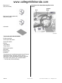
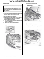
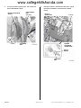
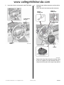
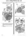
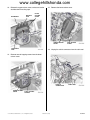
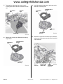
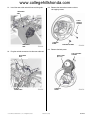
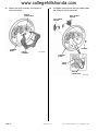
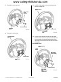
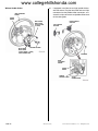
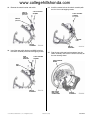
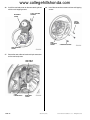
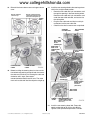
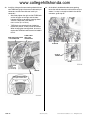
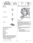
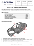
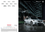
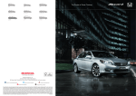
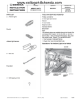
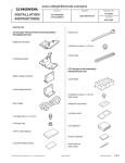
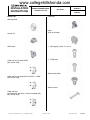
www.collegehillshonda.com
INSTALLATION
INSTRUCTIONS
Accessory
Application
HEATED STEERING WHEEL
P/N 08U97-TG7-100
2016 PILOT
PARTS LIST
Publications No.
VERSION 1
Issue Date
JUN 2015
Cable reel
Steering wheel
Control unit
HSW switch
Cable reel cord (marked RXXX)
(May not be used)
Relay
(May not be used)
2
Self-tapping screws, 4 x 12 mm
2
TORX bolts
Steering wheel bolt
Cable reel cord (marked CXXX: with ACC + LKAS)
(May not be used)
Switch bracket
Cable reel cord
(marked AXXX: with ACC + LKAS and paddle shift)
(May not be used)
© 2015 American Honda Motor Co., Inc. – All Rights Reserved.
AII01913-27 (1506)
08U97-TG7-1000-90
1 of 17
www.collegehillshonda.com
Body cover A
(May not be used)
Illustration of the Heated Steering Wheel in the
Vehicle
RELAY
STEERING
WHEEL
Body cover B (with paddle shift)
(May not be used)
Information
TOOLS AND SUPPLIES REQUIRED
Phillips screwdriver
10 mm Open end wrench
10 mm Hex wrench
Ratchet
T-30 TORX bit
Torque wrench
Steering wheel puller
Shop towel
Masking tape
HDS/MVCI
The following tool is available through the Honda Tool and
Equipment Program. On the iN, click on: Service >
Service Bay > Tool and Equipment Program, then enter
the number under “Search.” Or, call 888-424-6857.
• Trim Tool Set (T/N SOJATP2014)
2 of 17
AII01913-27 (1506)
© 2015 American Honda Motor Co., Inc. – All Rights Reserved.
www.collegehillshonda.com
INSTALLATION
•
Remove the front bulkhead cover.
FRONT BULKHEAD
COVER
Customer Information: The information in this
installation instruction is intended for use only by skilled
technicians who have the proper tools, equipment, and
training to correctly and safely add equipment to your
vehicle. These procedures should not be attempted by
“do-it-yourselfers.”
10 CLIPS
NOTE:
• Observe all safety notes and precautions in the Service
Manual in addition to those in this Installation
Instruction.
• Be careful not to damage the vehicle.
• After installing the steering wheel, you must align the
steering wheel spoke angle to the straight ahead
position by adjusting the front toe.
1. Turn the steering wheel so the front wheels are in the
straight-ahead position.
2. Wrap a shop towel around the hood latch.
•
•
HOOD LATCH
(Wrap with a shop towel.)
Remove the intake air tube.
Disconnect the negative cable from the battery,
and wait at least 3 minutes before you start to
install the steering wheel.
2 CLIPS
© 2015 American Honda Motor Co., Inc. – All Rights Reserved.
AII01913-27 (1506)
INTAKE AIR
TUBE
3 of 17
www.collegehillshonda.com
3.
Pull away the door opening seal, and remove the
driver’s dashboard side lid.
DRIVER’S DASHBOARD
SIDE LID
3 CLIPS
4.
DOOR OPENING
SEAL
(Pull away.)
Remove the driver’s dashboard under cover, unplug
the vehicle connectors, and release the vehicle
sensor.
VEHICLE
CONNECTORS
12 CLIPS
2 RETAINING
TABS
DRIVER’S
DASHBOARD
LOWER COVER
VEHICLE
SENSOR
2 RETAINING
TABS
4 of 17
AII01913-27 (1506)
© 2015 American Honda Motor Co., Inc. – All Rights Reserved.
www.collegehillshonda.com
5.
Lower the tilt lever, and remove the two TORX bolts.
6.
Unplug the two vehicle connectors and the vehicle
connector.
NOTE: Be careful not to damage the connectors.
VEHICLE
CONNECTOR
2 VEHICLE
CONNECTORS
2 TORX BOLTS
(Discard.)
2 LOCKING TABS
(Pull up.)
STEERING
WHEEL
STEERING WHEEL
AIRBAG
7.
© 2015 American Honda Motor Co., Inc. – All Rights Reserved.
AII01913-27 (1506)
Remove the airbag. Do not drop the removed airbag
or hit it on an object. Place the removed airbag in a
safe place with the pad surface (top) facing upward.
5 of 17
www.collegehillshonda.com
8.
With the front wheels aligned in the straight forward
position, unplug the vehicle connector from the cable
reel, and loosen the steering wheel bolt.
STEERING WHEEL
BOLT
(Loosen.)
11. Attach the masking tape to the upper column cover
as shown.
UPPER COLUMN
COVER
MASKING
TAPE
STEERING
WHEEL
PULLER
STEERING
WHEEL
PULLER
BOLT
VEHICLE
CONNECTOR
12. Using a plastic trim tool, release the two retaining
tabs.
RETAINING
TAB
STEERING
WHEEL
UPPER
COLUMN
COVER
RETAINING
TAB
STEERING
WHEEL BOLT
(Discard.)
9.
Using a steering wheel puller, release the steering
wheel. Do not thread the steering wheel puller bolts
in more than 5 mm (0.20 in.). When removing the
steering wheel, take care not to move the front
wheels.
10. Remove the steering wheel bolt, then remove the
steering wheel.
PLASTIC TRIM
TOOL
6 of 17
AII01913-27 (1506)
© 2015 American Honda Motor Co., Inc. – All Rights Reserved.
www.collegehillshonda.com
13. Release the upper column cover, and secure it to the
dashboard with masking tape.
DASHBOARD
MASKING
TAPE
15. Remove the lower column cover.
UPPER
COLUMN
COVER
LOWER COLUMN
COVER
2 RETAINING
TABS
SELF-TAPPING
SCREW
16. Unplug the vehicle connectors from the cable reel.
14. Remove two self-tapping screws from the lower
column cover.
VEHICLE
CONNECTORS
LOWER COLUMN
COVER
CABLE REEL
2 SELF-TAPPING
SCREWS
© 2015 American Honda Motor Co., Inc. – All Rights Reserved.
AII01913-27 (1506)
7 of 17
www.collegehillshonda.com
17. To prevent the cable reel from turning, attach
masking tape to the cable reel. Remove the cable
reel.
19. Install the steering angle sensor to the new cable
reel with six retaining tabs.
MASKING
TAPE
3 RETAINING
TABS
6 RETAINING
TABS
STEERING ANGLE
SENSOR
NEW CABLE
REEL
LOCKING PIN
(Discard.)
CABLE REEL
18. Remove the masking tape. Remove the steering
angle sensor.
6 RETAINING
TABS
20. Remove the tape from the vehicle 2-pin connector,
and remove the dummy connector from the vehicle
2-pin connector.
STEERING ANGLE
SENSOR
CABLE REEL
(Discard.)
TAPE
(Remove.)
8 of 17
AII01913-27 (1506)
VEHICLE 2-PIN
CONNECTOR
DUMMY
CONNECTOR
(Remove.)
© 2015 American Honda Motor Co., Inc. – All Rights Reserved.
www.collegehillshonda.com
21. Install the new cable reel with three retaining tabs.
23. Remove the two washer-screws and two
self-tapping screws.
3 RETAINING
TABS
2 SELFTAPPING
SCREWS
STEERING
WHEEL
NEW CABLE
REEL
2 WASHER-SCREWS
24. Remove the body cover.
22. Plug the vehicle connectors into the new cable reel.
BODY COVER
(Discard.)
NEW CABLE
REEL
STEERING
WHEEL
VEHICLE
CONNECTORS
© 2015 American Honda Motor Co., Inc. – All Rights Reserved.
4 SELF-TAPPING
SCREWS
AII01913-27 (1506)
9 of 17
www.collegehillshonda.com
25. Remove the switch assembly, and unplug the
vehicle connectors.
26. If equipped, remove the left and right paddle shifters
and unplug the vehicle connectors.
VEHICLE
CONNECTORS
RIGHT PADDLE
SHIFTER
LEFT PADDLE
SHIFTER
2 SCREWS
STEERING
WHEEL
SWITCH
ASSEMBLY
STEERING
WHEEL
CABLE
GUIDE
VEHICLE
CONNECTORS
10 of 17
AII01913-27 (1506)
© 2015 American Honda Motor Co., Inc. – All Rights Reserved.
www.collegehillshonda.com
27. Remove the cable reel cord.
29. Install the cable guide on the new steering wheel
with six retaining tabs.
NEW STEERING
WHEEL
CABLE REEL
CORD
(Discard.)
WASHER-SCREW
STEERING
WHEEL
CABLE GUIDE
6 RETAINING
TABS
28. Remove the cable guide.
STEERING WHEEL
(Discard.)
30. Install the new cable reel cord on the cable guide
with one washer-screw. Plug the new cable reel cord
4-pin connector into the new steering wheel 4-pin
connector, and secure the new cable reel cord to the
cable guide.
With Paddle Shifter
NEW STEERING
WHEEL
CABLE
GUIDE
NEW CABLE
REEL CORD
(marked AXXX)
CABLE GUIDE
6 RETAINING
TABS
WASHER-SCREW
NEW CABLE
REEL CORD
(marked AXXX)
4-PIN
CONNECTOR
© 2015 American Honda Motor Co., Inc. – All Rights Reserved.
AII01913-27 (1506)
11 of 17
www.collegehillshonda.com
Without Paddle Shifter
31. If equipped, install the left and right paddle shifters
with two screws. Plug the new cable reel cord 4-pin
connectors into the paddle shifter connectors, and
secure the 4-pin connectors and paddle shifter cords
on the cable guide.
NEW STEERING
WHEEL
CABLE
GUIDE
NEW CABLE
REEL CORD
(marked RXXX
or CXXX)
RIGHT PADDLE
SHIFTER
LEFT PADDLE
SHIFTER
WASHER-SCREW
NEW CABLE
REEL CORD
(marked RXXX or CXXX)
4-PIN CONNECTOR
2 SCREWS
NEW
STEERING
WHEEL
CABLE
GUIDE
PADDLE
SHIFTER CORD
12 of 17
AII01913-27 (1506)
4-PIN
CONNECTORS
© 2015 American Honda Motor Co., Inc. – All Rights Reserved.
www.collegehillshonda.com
32. Remove the switch bracket and switch.
34. Install the control unit on the switch assembly with
two 4 x 12 mm self-tapping screws.
3 SELF-TAPPING
SCREWS
SWITCH
BRACKET
(Discard.)
2 SELF-TAPPING
SCREWS,
4 x 12 mm
SWITCH
(Discard.)
CONTROL
UNIT
SWITCH
ASSEMBLY
SWITCH
ASSEMBLY
33. Install the new switch bracket and HSW switch on
the switch assembly with three self-tapping screws.
NEW
SWITCH
BRACKET
3 SELF-TAPPING
SCREWS
35. Plug the new cable reel cord connectors into the
switch assembly, and install the switch assembly on
the new steering wheel.
NEW STEERING
WHEEL
HSW
SWITCH
SWITCH
ASSEMBLY
© 2015 American Honda Motor Co., Inc. – All Rights Reserved.
NEW CABLE
REEL CORD
CONNECTORS
AII01913-27 (1506)
SWITCH
ASSEMBLY
13 of 17
www.collegehillshonda.com
36. Install the new body cover on the new steering wheel
with four self-tapping screws.
NEW BODY
COVER
38. Install the two washer-screws and two self-tapping
screws.
4 SELF-TAPPING
SCREWS
2 SELFTAPPING
SCREWS
NEW
STEERING
WHEEL
2 WASHER-SCREWS
NEW STEERING
WHEEL
37. Secure the new cable reel cord and 4-pin connectors
on the new body cover.
NEW CABLE
REEL CORD
4-PIN
CONNECTORS
14 of 17
NEW BODY
COVER
AII01913-27 (1506)
© 2015 American Honda Motor Co., Inc. – All Rights Reserved.
www.collegehillshonda.com
39. Reinstall the lower column cover and upper column
cover.
Rotate clockwise
until it stops.
Rotate counterclockwise
about three full turns until
the arrow mark points up.
ARROW
MARK
41. Install the new steering wheel to the steering column
shaft in the straight-ahead position:
• Route the new cable reel 2-pin connectors cord
through the opening in the new steering wheel.
Route the new cable reel 2-pin connectors cord
under the new cable reel cord, and secure it to
the cable guide.
• Plug the new cable reel cord 20-pin and 2-pin
connectors into the new cable reel.
• Check that the wire harnesses are not pinched.
STEERING
COLUMN SHAFT
NEW STEERING
WHEEL
CABLE REEL
PIN
NEW CABLE
REEL CORD
20-PIN
CONNECTOR
NEW CABLE
REEL 2-PIN
CONNECTORS
CORD
UPPER COLUMN
COVER
NEW STEERING
WHEEL
LOWER COLUMN
COVER
40. Before installing the steering wheel, make sure the
front wheels are pointing straight ahead, then center
the cable reel. Do this by first rotating the cable reel
clockwise until it stops, then rotate it
counterclockwise about three full turns. The arrow
mark on the cable reel label should point straight up.
NEW CABLE REEL
CORD 2-PIN
CONNECTOR
NEW STEERING
WHEEL BOLT
44-54 N·m
(32-40 lbf·ft)
NEW CABLE
REEL CORD
CABLE
GUIDE
NEW CABLE REEL 2-PIN
CONNECTORS CORD
(Route under the cable
reel cord.)
42. Install the new steering wheel bolt. Torque the
steering wheel bolt to 44-54 N·m (32-40 lbf·ft).
Tighten at the specified torque within 5 minutes.
© 2015 American Honda Motor Co., Inc. – All Rights Reserved.
AII01913-27 (1506)
15 of 17
www.collegehillshonda.com
43. Install the airbag on the new steering wheel with two
new TORX bolts (plug in the two new cable reel 2-pin
connectors and the new cable reel cord 1-pin
connector).
• Alternately tighten the right and left TORX bolts
so that the gaps on the right and left sides
between the horn pad and the steering wheel
are even. Torque the TORX bolts to
6.9-11.8 N·m (5.1-8.7 lbf·ft).
• TORX bolts are coated with non-hardening
thread lock sealant, so they cannot be reused.
When installing the steering wheel, be sure to
replace the TORX bolts with the ones included in
this kit.
NEW CABLE REEL CORD
1-PIN CONNECTOR
44. At the driver’s dashboard under cover opening,
locate the vehicle connector and install the relay as
shown. If a relay is already installed in the vehicle
connector, go to step 45.
2 NEW CABLE
REEL 2-PIN
CONNECTORS
FUSE BOX
VEHICLE
CONNECTOR
RELAY
2 NEW TORX
BOLTS
6.9-11.8 N·m
(5.1-8.7 lbf·ft)
AIRBAG
Make sure the clearances
are equal on both sides.
HORN PAD
16 of 17
AII01913-27 (1506)
© 2015 American Honda Motor Co., Inc. – All Rights Reserved.
www.collegehillshonda.com
45. Check that all wire harnesses are routed properly
and all connectors are plugged in.
46. Reinstall all removed parts except for the front
bulkhead cover and the intake air tube.
47. Reconnect the negative cable to the battery.
48. Reinstall the front bulkhead cover and the intake air
tube.
49. Connect the HDS/MVCI, and clear the DTCs.
50. Inspect the following items. If any abnormality is
found, perform troubleshooting as described in the
Service Manual of the vehicle.
• Press the ENGINE START/STOP BUTTON to
the ON mode: the SRS indicator should come on
for about 6 seconds and then go off.
• Make sure the horn and steering wheel switches
work properly.
51. Press and hold the audio power button for two
seconds to restore the audio and navi (if equipped)
system functions.
52. Reset the clock on vehicle without navi.
53. If necessary, restore the systems back to normal
operation as described in the Service Manual.
54. Make sure the steering wheel is in the straight-ahead
position with the front wheels. If the spoke angle of
the steering wheel is not in the straight-ahead
position with the front wheels, adjust the front toe as
described in the Service Manual.
55. Do the VSA sensor neutral position memorization as
described in the Service Manual.
© 2015 American Honda Motor Co., Inc. – All Rights Reserved.
AII01913-27 (1506)
17 of 17