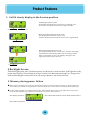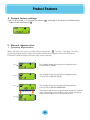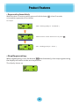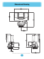
1
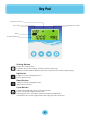
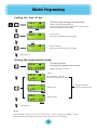
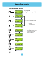
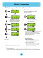
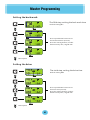
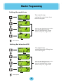
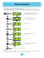
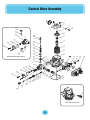
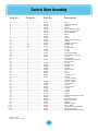
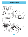
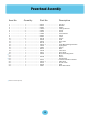
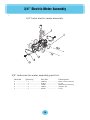
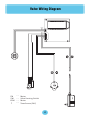
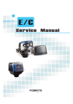
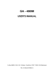
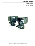
Service Manual
Table of Contents
Key Pad ....................................................................................................01
Master Programming .............................................................................02
Product Features .....................................................................................08
Dimensional Drawing .............................................................................11
Control Drive Assembly .........................................................................12
Powerhead Assembly .............................................................................14
3/4"Electric Meter Assembly ................................................................16
Valve Wiring Diagram ............................................................................17
Key Pad
Flow Meter Indicator
Time of day
Regeneration mode
Status
Volume Remaining
Setting Button
1.Enter into setting menu
2.Confirm the current setting, and enter into the next step.
3.When used simultaneously with up button, will enter into master programming.
Up Button
1. Adjust current settings(increase )
2.Go to the last step
Down Button
1.Adjust current setting(decrease )
2.Go to the next step
Cycle Button
1.Save the setting and return to ser vice interface.
2.Enter into queued regeneration mode.
3.A long press for 5-6 seconds, initiate a immediate regenerate.
4.Terminate the current regeneration step and goes to the next step.
01
Master Programming
Setting the time of day
The first step, Setting the time of day
Default setting 12:00 (24hous)
Press setting button and up button simultaneously
enter into programming mode
Flashing
Flashing
Set the hour
Press up or down button to change
Flashing
Set the minute
Press up or down button to change
Next option
Setting the regeneration mode
The second step,
Setting the regeneration mode
Default setting is " Timer "
Flashing
Timer
※ In
this mode, will not
show water capacity options
Flashing
Meter imm.
Press up and down
buttonto change mode
Flashing
Meter Delay
Flashing
Next option
Note:
Valve "MODE" always set piror to "the 4th step." Once change the "MODE" setting,
Please review and change the contents inside "the 4th step" accordingly
02
Master Programming
Setting the w ater c apacity
The third step,
Setting the water capacity (not show
in timer)
Default setting 1000 gal
Flashing
Flashing
Press up and down button
to set the unit
Flashing
:Gallen
: litre
: Cubic Meter
Flashing
Press up and down button
to set the water capacity
Press setting button, cursor
moves and the number
flashes one by one
Flashing
Flashing
Flashing
Flashing
Flashing
Next option
03
Master Programming
S e tting the r egeneration t ime a nd hour override
The fourth step,
Setting the Regeneration time
and hour override
Flashing
( M,TM)
(Timer)
Flashing
Flashing
Default hour override is 72 ,
Regeneration time: 02:00 AM
Set regeneration time(hour)
p ress up and down button to change .
In meter imm and meter delay
modes. Default setting of the
hour override is off.
Flashing
Flashing
Flashing
Flashing
Set hour override under meter imm and meter
delay, force regeneration will be activated,
and the valve will be forced into regeneration
when reached the set time.
Adjusting range, off-960, press the up and
down button to set.
Flashing
Press up and down to set the hour override
The adjusting range : 3-960
Next option
Mix regeneration :
●under meter imm mode
Meter imm and override hour are both
function, valve will start to regenerate
whenever which reaches first.
●under meter delay mode
Meter delay and override hour are both
function, Valve will start to regenerate
whenever which reaches first .
The way to adjust the valve of hour override:
1.Timer
1) The valve of hour override should be adjusted as divisible by 24 when it less than 24 hours ,
such as: 3,4,6,8,12,24.
2) The valve of hour override should be adjusted as 12 times when it over 24 hours,such as: 24,36,48,60.
2.Meter
The valve of hour override should be adjusted as 24 times,such as: 24,48,72,96.
04
Master Programming
Setting the back wash
The fifth step, setting the back wash time
Default setting 015
Flashing
Flashing
Press up and down button to set
the back wash time (minute)
Press the setting button, number
flashes one by one, range 0-999
Flashing
Flashing
Next option
Setting the brine
The sixth step, setting the brine time
Default setting 060
Flashing
Flashing
Press up and down button to set
the brine time (minute)
Press the setting button, number
flashes one by one, range 0-999
Flashing
Flashing
Next option
05
Master Programming
Setting the rapid rinse
The seventh step,
setting the rapid rinse time
Default setting 010
Flashing
Flashing
Press up and down button to set the
time of Rapid Rinse (minute)
Press the setting button, number
flashes one by one, range 0-999
Flashing
Flashing
Next option
Setting the brine tank fill
The eighth step,
setting the water filling time
Default setting 012
Flashing
Flashing
Press up and down button to set the
time of water filling (minute)
Press the setting button, number
flashes one by one, range 0-999
Flashing
Flashing
Next option
06
Master Programming
It´s available to modify any single step after whole setting is done. Via enter into
the main menu and press up and down button.
For instance: Under timer mode to modify, the fifth step: back wash, 30 minutes
Press setting button and up button
simultaneously to enter into programming
The first option is time of day
Flashing
Press down button three times and
enter into back wash setting
Flashing
Default setting
Flashing
Move cursor
Flashing
Press up button to increase the
number to 3
Flashing
闪烁
Move cursor
Flashing
Press down button to decrease the
number to 0
Flashing
Press the cycle button to save and exit.
Note:
Valve "MODE(the 2nd step)" always set piror to "the 4th step." Once change the "MODE(the 2nd step)"
setting, Please review and change the contents inside "the 4th step" accordingly.
07
Product Features
1. Full & clearly display in the Ser vice position
Timed Regeneration mode
The Display will show the current time, remaining time
to the next set regeneration.and the days override.
Reg. remain time
Reg.override days
Meter Immediate Regeneration mode
The Display will show the current time,
and the remaining treated water to the next regeneration.
Reg.remain capacity
Meter Delay Regeneration mode
The Display will show the current time, and the remaining
treated water alternatively. When the remaining treated
water countsdown to zero, the display changes to the
regeneration timeset by the user.
Reg.remain time
2.Backlight Screen
The backlight goes out if without press any button in one minute , and lighten on by
press any button . The edited data won´t save if no button pressing for a long time ,
and the backlight screen will turn off and go back to ser vice position .
3. Memor y during power failure
●
All program settings are stored in permanent memor y. Current valve position, cycle step elapsed,
time of day are stored during the power failure. Reset the current time is necessity when power up
●
If the valve stopped at a regeneration stage when power failure, the valve will return to the prior
position when power up. It takes 4 to 5 minutes to reset to the position.
the display shows as:
。the system will show the status when power failure
after find the position.
08
Product Features
4. Restore factory settings
Pull out the power
press the button
release the button
.
and plug in the power simultaneously
5. Manual regeneration
●
Queueing Regeneration
When the valve is in ser vice position,Press the button
into the“Que.Reg" interface.
Queueing Regeneration means the system will initiate a regeneration at the time set .
If missed, it will initiate at the same time of the next day.
.
The display shows for the Queued Regeneration
in the mode of TIMER .
Flashing
The display shows for the Queued Regeneration
in the mode of METER DELAY .
Flashing
The display shows for the Queued Regeneration
in the mode of METER IMMEDIATE.
Flashing
Alternating display
The system will initiate a regeneration either the treated
water remaining counts down to zero or the remaining
time counts down to zero, whichever is first.
Flashing
09
Product Features
● Regenerating Immediately
When the valve is in service position,press and hold the button
an immediate regeneration will be initiated.
at least 5 seconds,
for example:
“BW” Flashing (ready to “backwash”)
When the time counts down to zero or press
.
“BD” Flashing (ready to “brine” )
● Stop
Regenerating:
When regenerating, Press the button
simultaneously, then stop regenerating
the display will return to the ser vice position.
The display shows as:
10
Dimensional Drawing
The unit of the number in brackets is inch, rest is millimeter.
11
Control Drive Assembly
1
2
3
4
52
5
43
6
37
49
48
7
47
8
51
33
32
46
31
9
45
10
44
25
50
11
43
Backwash Filter Injector Option
42
38
41
39
40
12
13
14 15
16
37
36
34
35
33
32
22
31
25
24
21
20
23
19
17
18
26
27
28
29
30
53
Mixing Assembly
12
Control Drive Assembly
Item No.
Quantity
1 ………… ……………
2 ………………………
3 ………………………
4 ………………………
5 ………………………
6 ………………………
7 ………………………
8 ………………………
9 ………………………
10 ………………………
11 ………………………
12 ………………………
13 ………………………
14 ………………………
15 ………………………
※ 16 ………………………
17 ………………………
18 ………………………
19 ………………………
20 ………………………
21 ………………………
※ 22 ………………………
23 ………………………
※ 24 ………………………
25 ………………………
26 ………………………
27 ………………………
28 ………………………
29 ………………………
30 ………………………
31 ………………………
32 ………………………
33 ………………………
※ 34 ………………………
※ 35 ………………………
36 ………………………
37 ………………………
38 ………………………
39 ………………………
40 ………………………
41 ………………………
42 ………………………
43 ………………………
44 ………………………
45 ………………………
46 ………………………
47 ………………………
48 ………………………
49 ………………………
▲ 50 ………………………
▲ 51 ………………………
▲ 52 ………………………
53 ………………………
Part No.
3 ……………………… 02001 ………………………
1 ……………………… 56050 ………………………
1 ……………………… 04002 ………………………
1 ……………………… 02106 ………………………
1 ……………………… 66133 ………………………
1 ……………………… 66118 ………………………
1 ……………………… 56115 ………………………
1 ……………………… 56076-1 ……………………
5 ……………………… 56033 ………………………
4 ……………………… 56004 ………………………
1 ……………………… 56001-1 ……………………
4 ……………………… 01013 ………………………
2 ……………………… 56017 ………………………
2-4 …………………… 56051 ………………………
2-4 …………………… 02105 ………………………
1 ………………………………………………………….
1 ……………………… 01007 ………………………
1 ……………………… 01102 ………………………
1 ……………………… 56011 ………………………
1 ……………………… 56012 ………………………
1 ……………………… 01101 ………………………
1 ……………………….…………………………………
1 ……………………… 56015 ………………………
1 ……………………….…………………………………
1 ……………………… 01004 ………………………
1 ……………………… 56056 ………………………
1 ……………………… 56060 ………………………
1 ……………………… 56062 ………………………
1 ……………………… 56023 ………………………
1 ……………………… 56061 ………………………
2 ……………………… 02003 ………………………
1 ……………………… 56003 ………………………
1 ……………………… 01005 ………………………
1 ……………………….…………………………………
1 ……………………….…………………………………
1 ……………………… 56059 ………………………
1 ……………………… 56002 ………………………
2 ……………………… 01002 ………………………
1 ……………………… 56014 ………………………
1 ……………………… 01006 ………………………
1 ……………………… 01105 ………………………
1 ……………………… 56010 ………………………
1 ……………………… 01003 ………………………
1 ……………………… 66119 ………………………
1 ……………………… 56058 ………………………
1 ……………………… 56030 ………………………
1 ……………………… 56054-1 ……………………
1 ……………………… 04001 ………………………
1 ……………………… 04053 ………………………
1 ……………………… 56102 ………………………
1 ……………………… 56104 ………………………
1 ……………………… 56101 ………………………
1 ……………………… 66500 ………………………
Only for Filter。
▲
※ More model options。
13
Description
Screw
End Plug Retainer
Washer
Screw
Piston Rod Assembly
End Plug Assembly
Piston Retainer
Piston
Seal
Spacer
Valve Body Assembly
O-ring
Adapter Coupling
Adapter Clip
Screw
Yoke, Plastic
O-ring
O-ring
Drine House Barb
DLFC Button Retainer
O-ring
DLFC Button
BLFC Button Retainer
BLFC Button
O-ring
BLFC Fitting
Screen
adaptor
BLFC Ferrule
Nut
Screw
Injector Cover
O-ring
Injector Nozzle
Injector Throat
Screen, Injector
Injector Body
O-ring
Air Disperser
O-ring
O-ring
Spacer
O-ring
Brine Valve Cap Assembly
Spring
Brine Valve Seat
Brine Valve Stem
Washer
Retaining Ring
BLFC ,Plug
Injector Nozzle-Undrilled
Brine Valve, Plug
Mix Water Valve Assembly
Powerhead Assembly
14
Powerhead Assembly
Item No.
1
2
3
4
5
6
7
8
9
10
11
12
13
14
15
16
17
18
19
20
※ 21
22
※ 23
24
25
26
27
28
Quantity
………… …… ………
………………………
………………………
………………………
………………………
………………………
………………………
………………………
………………………
………………………
………………………
………………………
………………………
………………………
………………………
………………………
………………………
………………………
………………………
………………………
………………………
………………………
………………………
………………………
………………………
………………………
………………………
………………………
1
1
1
1
2
3
1
1
1
5
1
1
1
1
1
2
2
1
1
1
1
2
1
1
1
1
1
1
Part No.
……………………… 56219 ………………………
……………………… 56214 ………………………
……………………… 06003 ………………………
……………………… C0002 ………………………
……………………… 02054 ………………………
……………………… 02015 ………………………
……………………… 07098 ………………………
……………………… 56220 ………………………
……………………… 56294 ………………………
……………………… 02106 ………………………
……………………… 04002 ………………………
……………………… 15619 ………………………
……………………… 00105 ………………………
……………………… 15612-1 ……………………
……………………… 13253 ………………………
…………………… … 13252 ………………………
……………………… 09001 ………………………
……………………… 13205 ……………………….
……………………… 15617 ………………………
……………………… 15650 ………………………
…………………………………………………………
……………………… 02008 ………………………
…………………………………………………………
……………………… 07021 ………………………
……………………… 15601-1 ……………………
……………………… 07019 ………………………
……………………… 04003 ………………………
……………………… 15621 ………………………
※ More model options。
15
Description
Housing
Bracket
Switch
Wiring Harness
Screw
Screw
Circuit Board
Panel
Lable
Screw
Seal
Drive Cam
Pin
Knob,Manual Regeneration
Spring Idler
Spring
Ball
Idler Gear
Drive Gear
Motor Mounting Plate
Motor
Screw
Transformer
DC Monotrematous Socket
Main Gear
Strain relief
Seal
Brine Valve Gear
3/4’’ Electric Meter Assembly
3/4" turbo electric meter assembly
3/4" turbo electric meter assembly parts list
Item No.
1
2
3
4
5
Quantity
………………………
………………………
………………………
………………………
………………………
1
4
1
2
2
………………………
………………………
………………………
………………………
………………………
Part No.
Description
50022-5 ……………………
01013 ………………………
1220E ………………………
50044 ………………………
02105 ………………………
Meter cable assembly
O-ring
Meter body assembly
Adpater clip
Screw
16
Valve Wiring Diagram
Black
Blue
White
White
White
Blue
Blue
Yellow
Yellow
FM
SW
VDM
T
……
……
……
……
Meter
Valve Homing Switch
Motor
Transformer(24V)
17