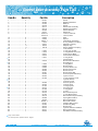
1
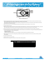
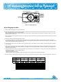
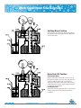
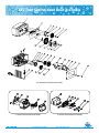
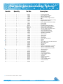
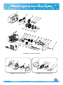
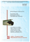
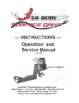
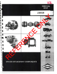
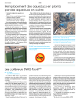
For Bright Future
F11 E C
Ser vice Manual
Table of Contents
Products Checking List .................................................................................1
General Residential Installation Check List .....................................................2
STC Timer Control Valve Start-up Procedures ...................................................3
FTC Blackwash Fliter Valve Start-up Procedures ..............................................4
SMM Meter Control Valve Start-up Procedures .................................................5
Water Conditioner Flow Diagrams ...................................................................6
STC Time Control Valve Drive Assembly ..........................................................10
Time Control Valve Drive Assembly Parts List ..................................................11
SMM Meter Control Valve Drive Assembly .......................................................12
Meter Control Valve Drive Assembly Parts List ................................................13
Control Valve Assembly ................................................................................14
Control Valve Assembly Parts List ..................................................................15
Meter Assembly and Parts list .......................................................................16
Products Checking List
Products series check
F11-STC(Softener time)
E-STC(Softener time)
C-STC(Softener time)
F11-SMM(Softener meter)
E-SMM(Softener meter)
C-SMM(Softener meter)
F11-FTC(Filter time)
E-FTC(Filter time)
C-FTC(Filter time)
Other model
Electric motor
220V/50Hz
120V/60Hz
24V/60Hz
220V/60Hz
Others
Flow meter
2100GALLON/Plastic(8T)
10800GALLON/Plastic(40T)
Yoke
3/4"NPT Plastic
1"NPT Plastic
1-3/4"NPT Plastic
Injector nozzle/throat
#0 Red
#1 Natual
#2 Blue
#3 Yellow
#4 Green (For china)
#2PVC Iron valve only
B.L.F.C
0.125GPM
0.25GPM
0.5GPM
1.0GPM(For china)
D.L.F.C
1.2GPM
1.5GPM
2.0GPM
2.4GPM
4.0GPM
5.0GPM
7.0GPM(For china)
3.0GPM
3.5GPM
Piston & Valve Position Dial
Standard
LW(Low Water)
Filter(For Filter Valve only)
Power Cord & Plug
CN
US
UK
EU
JP
Others
Input Power
☞ Parts chosen with ''X'' will be installed into the valve as default.
☞ Items in Gray indicate not often used or only for China.
Page 1
Tel-(8625)025-51180528
For Bright Future
http://www.fobrite.com
General Residential Installation Check List
Water Pressure
Minimum 25 PSI
Electrical Supply
Uninterrupted AC.Check voltage compatibility
Existing
Free of any deposits or build-ups inside pipes
Softener
Locate close to drain and connect according to plumbing codes
Bypass Valves
Always provide for bypass valve if unit is not equipped with one
CAUTION
¤ Do not exceed 120 PSI water pressure
¤ Do not exceed 100°F water temperature
WARNING
¤ Do not subject unit to freezing conditions
General Valve Installation Procedure
Note: Install the water softener with the inlet, outlet and drain connections made according to manufacturer’s recommendations and to
meet applicable plumbing codes.
1. Locate the softener tank close to a drain where you wish to install the unit.
Note: Be sure the tank is level and on a firm base.
2. Perform all plumbing according to local plumbing codes.
— Use a 1/2" minimum pipe size for the drain.
— Use a 3/4" drain line for backwash flow rates that exceed 7 gpm or length that exceeds 20′ (6 m).
3. Cut the 1" distributor tube (1.050 O.D.) flush with top of each tank.
Note: Only use silicone lubricant.
4. Lubricate the distributor o-ring seal and tank o-ring seal. Screw the valve on to the tank.
5. Use only Teflon tape on the drain fitting. Solder joints near the valve must be done before connecting any piping to the valve.
Always leave at least 6" (152 mm) between the valve and solder joints when soldering pipes that are connected to the valve. Failure
to do this could cause damage to the valve.
6. Be sure the floor under the brine tank is clean and level.
7. Add water until there is approximately 1" (25 mm) of water above the grid plate. If a grid is not utilized, fill to the top of the air check
in the brine tank. Do not add salt to the brine tank at this time.
8. On units with a bypass, place in Bypass position.
— Turn on the main water supply.
— Open a cold soft water tap nearby and let water run a few minutes or until the system is free of foreign material (usually solder)
resulting from the installation. Close the water tap when water runs clean.
9. Place the bypass in the In Service position and let water flow into the mineral tank. When water flow stops, slowly open a cold water
tap nearby and let water run until air is purged from the unit. Then close tap.
10.Plug the valve into an approved power source.
Page 2
Tel-(8625)025-51180528
For Bright Future
http://www.fobrite.com
STC Timer Control Valve Start-up Procedures
MANUAL REGENERATION KNOB
24 HOUR GEAR
SKIPPER WHEEL
(VALVE WILL
REGENERATE
TONIGHT WHEN
PULLED TAB IS
LINED UP WITH
RED POINTER)
WHITE TIME
SET BUTTON
TIME OF DAY ARROW
RED POINTER
Mode F11-STC&E-STC&C-STC
1. Manually index the softener control into the In Service position and let water flow into the resin tank. When the water flow stops,
open a softened water tap until all air is released from the lines. Then close tap.
Note: Manually dial the various regeneration positions by turning the knob on the front of the control until the indicator shows that
the softener is in the desired position.
2. Manually index the control to the Backwash position and allow water to flow at the drain for 3 or 4 minutes.
3. Remove back cover plate.
4. Make sure that the salt dosage is set as recommended by the manufacturer. If necessary, set salt according to the setting instruction
sheet. Manually index the control to the Brine Fill position and allow the brine tank to fill to the top of the air check.
5. Manually index the control to the Brine Draw position and allow the control to draw water from the brine tank until it stops.
6. Plug in the electrical cord and look in the sight hole in the back of the motor to see that it is running. Set the days that regeneration is
to occur by sliding tabs on skipper wheel upward .
—Each tab is one day.
—Finger at red pointer is tonight.
—Moving clockwise from red pointer, pull or push fingers to obtain the desired regeneration schedule.
7. Manually advance the control to the beginning of the Brine Fill position and allow the control to return to the In Service position
automatically.
8. Fill the brine tank with salt.
9. Replace back cover on the control.
10.Make sure that any bypass valving is left in the normal In Service position.
Softener Timer Regeneration Reference Chart
Page 3
Tel-(8625)025-51180528
For Bright Future
http://www.fobrite.com
FTC Blackwash Fliter Valve Start-up Procedures
MANUAL REGENERATION KNOB
24 HOUR GEAR
SKIPPER WHEEL
(VALVE WILL
REGENERATE
TONIGHT WHEN
PULLED TAB IS
LINED UP WITH
RED POINTER)
WHITE TIME
SET BUTTON
TIME OF DAY ARROW
RED POINTER
Mode F11-FTC&E-FTC&C-FTC
Before Plugging in the Unit
1. Open a treated water tap down stream of the filter.
2. Manually index the filter to the In Service position and allow the mineral tank to fill by slowly opening the main water supply valve.
Any bypass should be in the In Service position.
Note: The water flowing from the downstream tap is cloudy and/or contains media fines as well as air. Allow the water to run until it
appears clean and free of air.
3. When a steady clean flow appears at the tap, close the tap and the main water supply valve and allow the filter media bed to settle for
15–20 minutes.
4. Manually index the filter to the Backwash position.
5. To prevent a sudden surge of water and air, partially open the main water supply valve so that the flow at the drain of the filter is
approximately 1 gpm (3.7 Lpm). The water at the drain is cloudy again and/or contains media fines as well as air. Allow water to flow
at the drain until it appears clean and free of air.
6. Continue to open the water supply valve until it is completely open. Allow water to flow at the drain until all media fines are washed
out of the filter.
7. Manually index the filter to the In Service position, and again open the downstream tap. Check to be sure that the water flows clear.
If necessary, allow water to flow until all media fines are gone. If the tap is equipped with an aerator check that is not plugged with
media fines and pipe scale.
8. Plug in the electrical cord and look in the sight hole in the back of the motor to see that it is running. Set the days that regeneration is
to occur by sliding tabs on skipper wheel upward .
—Each tab is one day.
—Finger at red pointer is tonight.
—Moving clockwise from red pointer, pull or push fingers to obtain the desired regeneration schedule.
9. Set time of day by pushing white button and spin the 24-hour gear until the present time of day is visible above the time of day arrow.
Filter Timer Regeneration Reference Chart
Page 4
Tel-(8625)025-51180528
For Bright Future
http://www.fobrite.com
SMM Meter Control Valve Start-up Procedures
MANUAL REGENERATION KNOB
24 HOUR GEAR
WHITE DOT
WHITE TIME
SET BUTTON
PROGRAM WHEEL
TIME OF DAY ARROW
GALLON LABEL
Mode F11-SMM&E-SMM&C-SMM
1. Manually index the softener control to the In Service position and let water flow into the resin tank. When the water flow stops,
open a softened water tap until all air is released from the lines. Then close tap.
Note: The various regeneration positions may be dialed manually by turning the knob on the front of the control until the indicator
shows that the softener is in the desired position.
2. Set water usage program wheel :Calculate the gallon capacity of the system by dividing the system capacity by the raw water
hardness.Next subtract the necessary reserve requirement by multiplying the number of people in the house by 75 gallons
(1 US gallon=3.785 L) per day. Set the gallons available at the small white dot on program wheel gear.The capacity arrow denotes
remaining gallons exclusive of fixed reserve.The table below is also a quick reference to determine the gallons used before each
regeneration.
3. Rotate program wheel counterclockwise until it stops at Regeneration position.
4. Manually index the control to the Backwash position and allow water to flow at the drain for 3 or 4 minutes.
5. Remove back cover plate.
6. Make sure than the salt dosage is set as recommended by the manufacturer. Manually index the control to the Brine Fill position and
allow the brine tank to fill to the top of the air check.
7. Manually index the control to the Brine Rinse position and allow the control to draw water from the brine tank until it stops.
8. Plug in the electrical cord and look in the sight hole in the back of the motor to see that it is running.
9. Manually advance the control to the beginning of the Brine Fill position and allow the control to return to the In Service position
automatically.
10.Fill the brine tank with salt.
11.Replace back cover on the control. Be sure cable is not pinched between cover and housing.
12.Make sure that any bypass valving is left in the normal In Service position.
Capacity 18,000
1
2
3
4
5
6
No. Of
Persons
Capacity 24,000
1
2
3
4
5
6
No. Of
Persons
Hardness PPM (GPG)
85(5)
2,100
2,100
2,100
2,100
2,100
2,100
171(10)
1,725
1,650
1,575
1,500
1,425
1,350
256(15)
1,125
1,050
975
900
825
750
85(5)
2,100
2,100
2,100
2,100
2,100
2,100
171(10)
2,100
2,100
2,100
2,100
2,025
1,950
256(15)
1,525
1,450
1,375
1,300
1,225
1,150
342(20)
825
750
675
600
525
450
513(30)
525
450
375
300
225
150
684(40) 855(50)
375
285
300
210
225
135
150
60
75
0
0
0
Capacity 30,000
No. Of
Persons
Hardness PPM (GPG)
342(20)
1,125
1,050
975
900
825
750
513(30)
725
650
575
500
425
350
684(40) 855(50)
525
405
450
330
375
255
300
180
225
105
150
30
1
2
3
4
5
6
Capacity 36,000
1
2
3
4
5
6
No. Of
Persons
85(5)
2,100
2,100
2,100
2,100
2,100
2,100
171(10)
2,100
2,100
2,100
2,100
2,100
2,100
Hardness PPM (GPG)
256(15) 342(20) 513(30)
1,925
1,425
925
1,850
1,350
850
1,775
1,275
775
1,700
1,200
700
1,625
1,125
625
1,550
1,050
550
684(40) 855(50)
675
525
600
450
525
375
450
300
375
225
300
150
85(5)
2,100
2,100
2,100
2,100
2,100
2,100
171(10)
2,100
2,100
2,100
2,100
2,100
2,100
Hardness PPM (GPG)
256(15) 342(20) 513(30)
2,100
1,725
1,125
2,100
1,650
1,050
2,100
1,575
975
2,100
1,500
900
2,025
1,425
825
1,950
1,350
750
684(40) 855(50)
825
645
750
570
675
495
600
420
525
345
450
270
Softener Meter Capacity Reference Chart (Gallons)
Capacity 18,000
No. Of
Persons
1
2
3
4
5
6
Capacity 30,000
555
555
555
555
555
555
456
436
416
396
376
357
297
277
258
238
218
198
218
198
178
159
139
119
139
119
99
79
59
40
99
79
59
40
20
0
75
55
36
16
0
0
No. Of
Persons
555
555
555
555
555
555
555
555
555
555
535
515
403
383
363
343
324
304
297
277
258
238
218
198
192
172
152
132
112
92
139
119
99
79
59
40
107
87
67
48
28
8
No. Of
Persons
Capacity 24,000
No. Of
Persons
1
2
3
4
5
6
1
2
3
4
5
6
555
555
555
555
555
555
555
555
555
555
555
555
509
489
469
449
429
410
376
357
337
317
297
277
244
225
205
185
165
145
178
159
139
119
99
79
139
119
99
79
59
40
555
555
555
555
555
555
555
555
555
555
555
555
555
555
555
555
535
515
456
436
416
396
376
357
297
277
258
238
218
198
218
198
178
159
139
119
170
151
131
111
91
71
Capacity 36,000
1
2
3
4
5
6
Softener Meter Capacity Reference Chart (L)
Page 5
Tel-(8625)025-51180528
For Bright Future
http://www.fobrite.com
Water Conditioner Flow Diagrams
Service Position
Hard water enters unit at valve inlet and flows
down through the mineral in the mineral tank.
Conditioned water enters center tube through
the bottom distributor, then flows up through
the center tube, around the piston, and out the
outlet of the valve.
Preliminary Rinse Position
Slow rinse of the resin bed. Water flows down
through the resin bed up the bottom distributor
and out the drain.
Page 6
Tel-(8625)025-51180528
For Bright Future
http://www.fobrite.com
Water Conditioner Flow Diagrams
Backwash Position
Hard water enters unit at valve inlet, flows
through piston, down center tube, through
bottom distributor, and up through the mineral,
around the piston and out the drain line.
Water is passed through the resin bed in the
opposite direction of normal flow, which flushes
suspended matter out of the resin tank.
Backwashing also loosens the resin bed which
becomes compacted during the softening
(in service) cycle.
Brine Position
(Softeners Only)
Hard water enters unit at valve inlet, flows up
into injector housing and down through nozzle
and throat to draw brine from the brine tank,
brine flows down through mineral and enters
the center tube through bottom distributor and
out through the drain line.
The resin beads are washed with the strong
solution of salt water which is called the brine
solution.
Since the resin beads prefer calcium and
magnesium ions.
Page 7
Tel-(8625)025-51180528
For Bright Future
http://www.fobrite.com
Water Conditioner Flow Diagrams
Slow Rinse Position
(Softeners Only)
After all the brine has been drawn from the brine
tank,hard water continues to enter through the
valve inlet,flows around the lower piston groove,
and through the nozzle and throat,down through
the resin and into the distributor,then up through
the center tube,at last through the center hole in
the piston and out the drain line.
Rapid Rinse Position
(Second Backwash Position )
The resin bed is rinsed to remove excess brine
solution from the tank and the resin beads are
then ready to produce soft water again.
Hard water enters unit at valve inlet, flows
through piston, down center tube, through
bottom distributor, and up through the mineral,
around the piston and out the drain line.
Page 8
Tel-(8625)025-51180528
For Bright Future
http://www.fobrite.com
Water Conditioner Flow Diagrams
Settling Rinse Position
Slow rinse of the resin bed. Water flows down
through the resin bed up the bottom distributor
and out the drain.
Brine Tank Fill Position
(Softeners Only)
Hard water enters unit at valve inlet, flows up
through the injector housing, through the brine
valve to refill the brine tank. Valve is now
delivering soft water to the home. Raw water is
refilling the brine tank to make a brine solution
for the next regeneration
Note:Regeneration
When the valve is in Regeneration, raw water is
being passed to service until rapid rinse is
complete.
Page 9
Tel-(8625)025-51180528
For Bright Future
http://www.fobrite.com
STC Time Control Valve Drive Assembly
F11-STC Time Control Valve Drive Assembly
C-STC Time Control Valve Drive Assembly
E-STC Time Control Valve Drive Assembly
Page 10
Tel-(8625)025-51180528
For Bright Future
http://www.fobrite.com
Time Control Valve Drive Assembly Parts List
Item No.
1
2
3
4
5
6
7
8
9
10
11
12
13
14
15
16
17
18
19
20
21
22
23
※24
25
26
27
28
29
※30
31
32
33
34
35
36
37
38
39
40
41
Quantity
………………………
………………………
………………………
………………………
………………………
………………………
………………………
………………………
………………………
………………………
………………………
………………………
Part No.
1
1
1
2
4
1
1
1
1
1
1
2
Description
……………………… 66167 ………………………
……………………… 15680 ………………………
……………………… 13208 ………………………
……………………… 13254 ………………………
……………………… 09001 ………………………
……………………… 66109 ………………………
……………………… 13210 ………………………
……………………… 02107 ………………………
……………………… 13281 ………………………
……………………… 02103 ………………………
……………………… 56215 ………………………
……………………… 15605-1 ………………………
15605-2 ………………………
……………………… 1 ……………………… 66115 ………………………
……………………… 1 ……………………… 13211 ………………………
……………………… 2 ……………………… 02002 ………………………
……………………… 2 ……………………… 13252 ………………………
……………………… 1 ……………………… 15601 ………………………
……………………… 1 ……………………… 13206 ………………………
……………………… 1 ……………………… 13253 ………………………
……………………… 1 ……………………… 13205 ………………………
……………………… 1 ……………………… 13204 ………………………
……………………… 1 ……………………… 15650 ………………………
……………………… 6 ……………………… 02106 ………………………
……………………… 1 …………………………………………….……………
……………………… 2-3 ……………………… 02008 ………………………
……………………… 2 ……………………… 07002 ………………………
……………………… 1 ……………………… 15607 ………………………
……………………… 1 ……………………… 04003 ………………………
……………………… 1 ……………………… 66112 ………………………
66113 ………………………
66114 ………………………
……………………… 1 …………………………………………………….…...
……………………… 1 ……………………… 07003 ………………………
……………………… 1 ……………………… 56203 ………………………
……………………… 1 ……………………… 66169 ………………………
……………………… 1 ……………………… 56283 ………………………
……………………… 1 ……………………… 56202 ………………………
……………………… 1 ……………………… 56205 ………………………
……………………… 1 ……………………… 66168 ………………………
……………………… 1 ……………………… 56229 ………………………
……………………… 1 ……………………… 56281 ………………………
……………………… 1 ……………………… 56216 ………………………
……………………… 2 ……………………… 02004 ………………………
Housing Assembly
Front Label(F11 Timer)
Skipper Wheel Ring
Spring,Detent,Skipper Wheel
Ball
Skipper Wheel Assembly,12-Day
Regeneration Pointer
Screw,Skipper Wheel Assembly
Cover Label
Screw,Knob
Knob,Manual Regeneration
Valve Position Dial,Standard
Valve Position Dial,Fliter
24-hour Gear Assembly,Silver
Cycle Actuator Gear
Screw-Driver Mounting
Spring,Detent,Main Gear
Main Gear and Shaft
Idler Pointer
Spring Idler
Idler Gear
Drive Gear
Motor Mounting Plate
Screw
Motor
Screw,Motor mtg.and Ground wire
Wire Connector
Back Cover
Washer
Brine Cam Assembly,3.5-15Ibs
Brine Cam Assembly,4-6kg
Brine Cam Assembly,7-30Ibs
Electrical Cord
Strain Relief
Back Plate
Housing Assembly
Front Label(C Timer)
Front Cover
Housing
Bracket Assembly
Rubber Pad
Front Label(E Timer)
Dustproof Plate
Screw
※ For more options please refer to Page 1
Page 11
Tel-(8625)025-51180528
For Bright Future
http://www.fobrite.com
SMM Meter Control Valve Drive Assembly
3
2
1
F11-SMM Meter Control Valve Drive Assembly
38
4
5
39 40
41
6
42
7
C-SMM Meter Control Valve Drive Assembly
43
E-SMM Meter Control Valve Drive Assembly
Page 12
Tel-(8625)025-51180528
For Bright Future
http://www.fobrite.com
Meter Control Valve Drive Assembly Parts List
Item No.
1
2
3
4
5
6
7
8
9
10
11
12
13
14
15
16
17
18
19
20
※21
22
23
24
25
26
27
28
29
30
31
※32
33
34
35
36
37
38
39
40
41
42
43
Quantity
………………………
………………………
………………………
………………………
………………………
………………………
………………………
………………………
………………………
Part No.
1
1
1
1
8
2
1
1
1
Description
……………………… 66167 ………………………
……………………… 15688 ………………………
……………………… 66116 ………………………
……………………… 13109 ………………………
……………………… 02106 ………………………
……………………… 13281 ………………………
……………………… 02103 ………………………
……………………… 56215 ………………………
……………………… 15605-1 ………………………
15605-2 ………………………
……………………… 1 ……………………… 66115 ………………………
……………………… 1 ……………………… 15608 ………………………
……………………… 2 ……………………… 02002 ………………………
……………………… 2 ……………………… 13252 ………………………
……………………… 2 ……………………… 09001 ………………………
……………………… 1 ……………………… 15601 ………………………
……………………… 1 ……………………… 13206 ………………………
……………………… 1 ……………………… 13253 ………………………
……………………… 1 ……………………… 13205 ………………………
……………………… 1 ……………………… 13204 ………………………
……………………… 1 ……………………… 15650 ………………………
……………………… 1 ………………………………………………………...
……………………… 2-3 ……………………… 02008 ………………………
……………………… 2 ……………………… 07002 ………………………
……………………… 1 ……………………… 15607 ………………………
……………………… 1 ……………………… 12151 ………………………
……………………… 1 ……………………… 13106 ………………………
……………………… 1 ……………………… 13151 ………………………
……………………… 1 ……………………… 13107 ………………………
……………………… 1 ……………………… 56206 ………………………
……………………… 1 ……………………… 04003 ………………………
……………………… 1 ……………………… 66112 ………………………
66113 ………………………
66114 ………………………
……………………… 1 ………………………………….……………….……..
……………………… 1 ……………………… 07003 ………………………
……………………… 1 ……………………… 56203 ………………………
……………………… 1 ……………………… 66169 ………………………
……………………… 1 ……………………… 56284 ………………………
……………………… 1 ……………………… 56202 ………………………
……………………… 1 ……………………… 56205 ………………………
……………………… 1 ……………………… 66168 ………………………
……………………… 1 ……………………… 56229 ………………………
……………………… 1 ……………………… 56281 ………………………
……………………… 1 ……………………… 56216 ………………………
……………………… 2 ……………………… 02004 ………………………
Housing Assembly
Front Label(F11 Meter)
Program Skipper Wheel Assembly
Program Wheel Retainer
Screw
Cover Label
Screw,Knob
Knob,Manual Regeneration
Valve Position Dial,Standard
Valve Position Dial,Fliter
24-hour Gear Assembly,Silver
Cycle Actuator Gear
Screw-Driver Mounting
Spring,Detent,Main Gear
Ball
Main Gear and Shaft
Idler Pointer
Spring Idler
Idler Gear
Drive Gear
Motor Mounting Plate
Motor
Screw,Motor mtg.and Ground wire
Wire Connector
Back Cover
Cable Assembly
Spring Retainer
Spring
Clutch,Drive Pinion
Drive Pinion,Program Wheel
Washer
Brine Cam Assembly,3.5-15Ibs
Brine Cam Assembly,4-6kg
Brine Cam Assembly,7-30Ibs
Electrical Cord
Strain Relief
Back Plate
Housing Assembly
Front Label(C Meter)
Front Cover
Housing,With Pin
Bracket Assembly
Rubber Pad
Front Label(E Meter)
Dustproof Plate
Screw
※ For more options please refer to Page 1
Page 13
Tel-(8625)025-51180528
For Bright Future
http://www.fobrite.com
Control Valve Assembly
Backwash Filter Injector Option
Mix Water Valve Option
Page 14
Tel-(8625)025-51180528
For Bright Future
http://www.fobrite.com
Control Valve Assembly Parts List
Item No.
1
2
3
4
5
6
7
8
9
10
11
12
13
14
15
16
※17
18
19
20
21
22
※23
24
※25
26
27
28
29
30
31
32
33
34
※35
※36
37
38
39
▲40
41
42
43
44
45
46
47
48
49
50
51
52
53
54
Quantity
………………………
………………………
………………………
………………………
………………………
………………………
………………………
………………………
………………………
3
1
1
1
1
1
1
1
1
Part No.
………………………
………………………
………………………
………………………
………………………
………………………
………………………
………………………
………………………
Description
02001 ………………………
56050 ………………………
04002 ………………………
02106 ………………………
66117 ………………………
66118 ………………………
56006 ………………………
00101 ………………………
56053-1 ………………………
56150-2 ………………………
……………………… 5 ……………………… 56033 ………………………
……………………… 4 ……………………… 56004 ………………………
……………………… 1 ……………………… 56001-1 ……………………...
……………………… 4 ……………………… 01013 ………………………
……………………… 2 ……………………… 56017 ………………………
……………………… 2-4 ……………………… 56051 ………………………
……………………… 2-4 ……………………… 02105 ………………………
……………………… 1 ………………………………………………………….
……………………… 1 ……………………… 01007 ………………………
……………………… 1 ……………………… 01102 ………………………
……………………… 1 ……………………… 56011 ………………………
……………………… 1 ……………………… 56012 ………………………
……………………… 1 ……………………… 01101 ………………………
……………………… 1 ……………………….…………………………………
……………………… 1 ……………………… 56015 ………………………
……………………… 1 ……………………….…………………………………
……………………… 1 ……………………… 01004 ………………………
……………………… 1 ……………………… 56056 ………………………
……………………… 1 ……………………… 56060 ………………………
……………………… 1 ……………………… 56062 ………………………
……………………… 1 ……………………… 56023 ………………………
……………………… 1 ……………………… 56061 ………………………
……………………… 2 ……………………… 02003 ………………………
……………………… 1 ……………………… 56003 ………………………
……………………… 1 ……………………… 01005 ………………………
……………………… 1 ……………………….…………………………………
……………………… 1 ……………………….…………………………………
……………………… 1 ……………………… 56059 ………………………
……………………… 1 ……………………… 56002 ………………………
……………………… 2 ……………………… 01002 ………………………
……………………… 1 ……………………… 56014 ………………………
……………………… 1 ……………………… 01006 ………………………
……………………… 1 ……………………… 01105 ………………………
……………………… 1 ……………………… 56010 ………………………
……………………… 1 ……………………… 01003 ………………………
……………………… 1 ……………………… 66119 ………………………
……………………… 1 ……………………… 56058 ………………………
……………………… 1 ……………………… 56030 ………………………
……………………… 1 ……………………… 56054-1 ………………………
……………………… 1 ……………………… 04001 ………………………
……………………… 1 ……………………… 04053 ………………………
……………………… 1 ……………………… 56102 ………………………
……………………… 1 ……………………… 56104 ………………………
……………………… 1 ……………………… 56101 ………………………
……………………… 1 ……………………… 66500 ………………………
Only used in Filte r
▲
※ For more options please refer to
Screw
End Plug Retainer
Washer
Screw
Piston Rod Assembly
End Plug Assembly
Piston Retainer
Piston Pin
Piston, Softener
Piston, Filter
Seal
Spacer
Valve Body Assembly
O-ring,Adapter Coupling
Adapter Coupling
Adapter Clip
Screw,Adapter Coupling
Yoke,Plastic
O-ring,Top of tank
O-ring,Distributor Tube
Drine House Barb
DLFC Button Retainer
O-ring,DLFC
DLFC Button
BLFC Button Retainer
BLFC Button
O-ring,BLFC
BLFC Fitting
Screen, Brine Line
BLFC Tube Insert
BLFC Ferrule
BLFC Fitting Nut
Screw Injector Mounting
Injector Cover
O-ring,Injector Cover
Injector Nozzle
Injector Throat
Screen,Injector
Injector Body
O-ring Injector
Air Disperser
O-ring,Drain
O-ring
Brine Valve Spacer
O-ring,Brine Valve
Brine Valve Cap Assembly
Spring,Brine Valve
Brine Valve Seat
Brine Valve Stem
Washer,Brine Valve
Retainning Ring
BLFC,Plug
Injector Nozzle-Undrilled
Brine Valve,Plug
Mix Water Valve Assembly
Page 1
Page 15
Tel-(8625)025-51180528
For Bright Future
http://www.fobrite.com
Meter Assembly and Parts list
Item No.
Quantity
1 ………………………
2A ………………………
2B ………………………
3 ………………………
4 ………………………
5 ………………………
6 ………………………
7 ………………………
8 ………………………
9 ………………………
4
1
1
1
1
4
4
4
1
1
Part No.
………………………
………………………
………………………
………………………
………………………
………………………
………………………
………………………
………………………
………………………
02082
66120A
66120B
01015
12204A
02105
56051
01013
12001
56013
Description
………………………
………………………
………………………
………………………
………………………
………………………
………………………
………………………
………………………
………………………
Screw,Meter Cover Assembly
Meter Cover Assembly,10600gal
Meter Cover Assembly,2100gal
O-ring,Meter Cover Assembly
Impeller
Screw,Adapter Clip
Adapter Clip
O-ring,Meter Body
Meter Body
Flow Straightener
Page 16
Tel-(8625)025-51180528
For Bright Future
http://www.fobrite.com
NO.2 Ailing Road,Moling,Jiangning Development Zone
Nanjing,China
P.C: 211111
TEL: 025-51180528
FAX: 025-51180529
www.fobrite.com
[email protected]