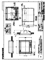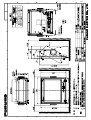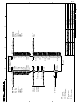
1
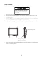
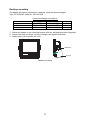
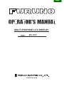
Back
MULTI-PURPOSE LCD DISPLAY
MU-120C
www.furuno.co.jp
SAFETY INSTRUCTIONS
Safety Instructions for the Operator
Safety Instructions for the Installer
WARNING
WARNING
Do not open the equipment.
Do not open the cover
unless totally familiar with
electrical circuits and
service manual.
Only qualified personnel
should work inside
the equipment.
Improper handling can result
in electrical shock.
Do not disassemble or modify the
equipment.
Fire, electrical shock or serious injury can
result.
Turn off the power at the switchboard
before beginning the installation.
Use the proper fuse and power cable.
Fire or electrical shock can result if the
power is left on.
Fuse rating is shown on the equipment.
Use of a wrong fuse can result in damage
to the equipment.
Do not install the equipment where it
may get wet from rain or water splash.
Immediately turn off the power at the
switchboard if the equipment is emitting
smoke or fire.
Water in the equipment can result in fire,
electrical shock or damage to the equipment.
Continued use of the equipment can cause
fire or electrical shock. Contact a FURUNO
agent for service.
CAUTION
Observe the following compass safe
distances to prevent interference to a
magnetic compass:
CAUTION
Standard
compass
Do not connect/disconnect the signal
cable while turning the power on.
The unit may be damaged.
A warning label is attached to the
equipment. Do not remove the label.
If the label is missing or damaged,
contact a FURUNO agent or dealer.
WARNING
To avoid electrical shock, do not
remove cover. No user-serviceable
parts inside.
Steering
compass
LCD Monitor MU-120C
0.75 m
0.5 m
Remote Controller
RMC-200
0.3 m
0.3 m
When lifting the display unit, hold it
together with the cover.
Grasping by the cover alone may allow
the display unit to fall, resulting in possible
bodily injury or damage to the equipment.
Name: Warning Label (1)
Type: 86-003-1011-1
Code No.: 100-236-231
i
TABLE OF CONTENTS
FOREWORD ........................................................................................................ iii
SYSTEM CONFIGURATION................................................................................ iv
EQUIPMENT LISTS .............................................................................................. v
1 MOUNTING ...................................................................................................... 1
1.1 Display Unit..................................................................................................................... 1
1.2 Remote Controller ........................................................................................................... 4
2 WIRING............................................................................................................. 5
3 ADJUSTMENTS ............................................................................................... 7
3.1 RGB/DVI Setting ............................................................................................................. 7
3.2 VIDEO Setting................................................................................................................. 9
3.3 Menu Window Setting ................................................................................................... 10
3.4 Remote Controller Setting ............................................................................................. 12
4 OPERATION ................................................................................................... 13
4.1 Controls......................................................................................................................... 13
4.2 Adjusting Display Brilliance............................................................................................ 15
4.3 Choosing Source for Main Picture ................................................................................. 16
4.4 Choosing Source for Picture-in-Picture.......................................................................... 17
5. MAINTENANCE, TROUBLESHOOTING....................................................... 18
5.1 Maintenance.................................................................................................................. 18
5.2 Troubleshooting............................................................................................................. 19
5.3 Clearing the Memory ..................................................................................................... 20
SPECIFICATIONS........................................................................................... SP-1
PACKING LISTS ............................................................................................... A-1
OUTLINE DRAWINGS ...................................................................................... D-1
INTERCONNECTION DIAGRAM ......................................................................S-1
ii
FOREWORD
A Word to the Owner of the MU-120C
FURUNO Electric Company thanks you for purchasing the MU-120C 12.1” Multi-Purpose
LCD Display. We are confident you will discover why the FURUNO name has become
synonymous with quality and reliability.
For over 50 years FURUNO Electric Company has enjoyed an enviable reputation for
quality and reliability throughout the world. This dedication to excellence is furthered by our
extensive global network of agents and dealers.
Your equipment is designed and constructed to meet the rigorous demands of the marine
environment. However, no machine can perform its intended function unless properly
installed and maintained. Please carefully read and follow the operation, installation and
maintenance procedures set forth in this manual.
We would appreciate feedback from you, the end-user, about whether we are achieving our
purposes.
Thank you for considering and purchasing FURUNO.
Features
• Main or remote display for radars, video sounders, sonars, plotter. Compatible
equipment: FAR-21X7 series, MODEL1833C/1833C-BB series (NavNet), FCV-1200L,
CH-250, CH-270, CSH-5L/8L, GD/GP-280/380/680, etc.
• High resolution display of 800 x 600dot (SVGA)
• Brightness of 1,000 cd/m2 (maximum) and 5 cd/m2 (minimum) for comfortable viewing
day and night
• Landscape orientation
• Wide viewing angle for observation by more than one person
• Picture-in-picture function
iii
SYSTEM CONFIGURATION
RGB
Radar, Video Plotter,
Navigator, Video Sounder, Scanning Sonar, etc.
DVI
12-24 VDC
FAR-2107 series etc.
VIDEO (NTSC/PAL)
CCD camera, Video recorder, etc.
Connectable equipment
Equipment
Resolution
Signal
FR-1510 MK3 series
XGA
Analog
FCV-1200L*
VGA
Analog, via IF8000
GD/GP-280/380/680
VGA
Analog
CH-250
VGA
Analog, via IF8000
CH-270
VGA
Analog, via IF8000
CSH-5L/8L
XGA
Analog
FSV-24/24S/30/30S
SXGA
Analog
FR-21X5 series
SXGA
Analog
FAR-21X7 series
SXGA
DVI
FEA-2107
SXGA
DVI
MODEL 1833C series
VGA
Analog
MODEL 1833C-BB series
VGA
Analog
*= Not available for the portrait type.
Note: The resolution of MU-120C is SVGA. VGA, XGA and SXGA signal may not be sharp
in character or scan line.
About the TFT LCD
The TFT LCD is constructed using the
latest LCD techniques, and displays
99.99% of its pixels. The remaining 0.01%
of the pixels may drop out or blink, however this is not an indication of malfunction.
iv
EQUIPMENT LISTS
Standard supply
Name
Type
Code No.
Qty
Display Unit
MU-120C
−
1
Remote Controller
RMC-200
000-012-629
1
Spare Parts*
SP19-00101
001-403-170
1 set
Installation Materials*
CP19-00100
000-012-630
1 set
Accessories*
FP19-00601
001-403-200
1 set
Remarks
w/LCD cover
Power cable
Option
Name
Hanger
Cable Assy
Remote
Controller
Type
Code No.
Qty
Remarks
001-403-240
1
w/knob, self-tapping screws
000-146-500
1
Cable length: 5 m
000-146-501
1
Cable length: 10 m
DVI-D/D SINGLELINK5M
000-149-054
1
Cable length: 5 m
RMC-200
000-012-629
1
FP19-00700
3COX-2P-6C
* = See packing list at end of manual.
v
vi
1 MOUNTING
Refer to the outline drawing at the end of the manual for mounting dimensions.
Note: A grass plate covers the LCD. For this reason, handle the unit carefully.
1.1 Display Unit
The display unit may be mounted on a desktop (optional hanger required) or flush mounted
in a panel.
When selecting a mounting location, keep in mind the following points:
• Locate the unit out of direct sunlight.
• Select a location where the display can be easily viewed and the controls can be easily
operated.
• Leave sufficient space around the unit for servicing and maintenance. See the outline
drawing for minimum servicing space.
• The unit weighs 5.4 kg (flush mounting)/6.3 kg (desktop mounting). Be sure the
mounting location is strong enough to support the weight of the unit.
• Locate the unit away from areas subject to water splash and rain.
1
Flush mounting
See the outline drawing at the end of the manual for mounting dimensions.
CAUTION
Hold the cover and display unit
together when lifting the display unit.
The display unit may fall out if only the
cover is held.
1. Remove the LCD cover from the unit.
2. Using the paper template supplied in the installation materials, make a cutout in the
mounting location.
3. Insert the display unit to the cutout, and fasten the display unit to the mounting location
with four self-tapping screws (5x40, supplied as accessories).
Note: Hex head bolts may also be used to fasten the display unit. However, their lengths
should be such that they extend at least 10 mm beyond the bulkhead.
Waterproofing: IP20
Cosmetic cap
Waterproofing: IPX5
Mounting dimensions
4. Attach the cosmetic caps (supplied as accessories) to the display unit at the locations
shown in the drawing above.
2
Desktop mounting
The display unit can be mounted on a desktop, using the optional hanger,
Type: FP19-00700, Code No.: 001-403-240.
Contents of hanger mounting kit
Name
Hanger
Knob bolt
Self-tapping screw
Type
FP19-00701
FP19-01402
5x20
Code No.
001-403-250
001-026-770
000-162-608-10
Qty
1
2
4
1. Fasten the hanger to the mounting location with four self-tapping screws (supplied).
2. Screw knob bolts in hanger, set unit to hanger, and tighten knob bolts.
3. Attach hard cover to protect the LCD.
Knob bolt
Hanger
Desktop mounting
3
1.2 Remote Controller
Write the device name (ex. “FCV-1200L”) for each “signal” key on the sticker supplied with
the remote controller. Attach the sticker to the remote controller, at the location shown
below.
RGB1
RGB2
DVI
VIDEO1
VIDEO2
VIDEO3
PIP1
PIP2
PIP3
+
MENU
BRILL
RGB 1 :
RGB2 :
DVI :
VIDEO1:
VIDEO2:
VIDEO3:
Sticker
Remote controller RMC-200
WARNING
Ensure battery polarity is correct.
Wrong polarity may cause the batteries to explode. 4
2 WIRING
Connect external equipment to the MU-120C by referring to the drawings below, the table
on the next page and the interconnection diagram at the back of this manual.
Ground terminal
12-24VDC
12-24 DVC
MJ-A3SPF0025-035C
(Supplied)
VIDEO1
VIDEO2
FAR-21X7 series
FEA-2107
DVI-D
VIDEO3
DVI-D/D SINGLELINK5M
(Option)
2.5C2V or 3C2V
(Local supply)
RGB1
RGB2
3COX-2P-6C (Option)
Display unit, rear view
5
CCD camera,
Video recorder, etc.
FCV-1200L
CH-250/S
CSH-5L/8L
FSV-24/24S/30/30S
GP/GD-280/380/680
FR-1510 MARK-3 series
FR-21X5 series
MODEL1833C series
MODEL1833C-BB series
Port, cable and connectable equipment
Used cable
Port
Name
12-24
VDC
DVI-D
RGB1
Type
Code No.
Standard/
Option
Connectable Equipment
Power
cable
DVI
Cable
MJ-A3SPF0025035C
DVI-D/D
SINGLELINK5M
000-156-05910
Standard
Power source
000-149-054
Option
3COX-2P-6C
5M
000-146-500
Option
3COX-2P-6C
10M
000-146-501
Option
Analog
RGB
Cable
RGB2
VIDEO1
Name
PC, FAR-21X7 series,
FEA-2107
FCV-1200L, CH-250,
CH-270, CSH-5L/8L,
FSV-24/24S/30/30S,
GD-280/380/680,
FR1510Mk-3,
FR-21X5 series,
Model 1833C series,
Model 1833C-BB series
Prepare the following cable locally.
▪ Connector type: RCA (metal), both ends
▪ Cable length: shorter than 10 m
▪ 2.5C2V or 3C2V (Japan Industrial Standard, or the
equivalent) coaxial cable (Impedance: 75 Ω)
Cable 3C2V
Insulator
VIDEO2
Video cassette
recorder, CCD camera,
DVD player
Shield
Vinyl
sheath
VIDEO3
Conductor 2
S = 0.19 mm
∅ = 0.5 mm
Grounding
Fasten the ground wire (local supply) between the ground terminal on the display unit and
the ship’s superstructure. The length should be as short as possible.
) to make the ground connection at the display unit. Do
Note: Use a “closed-type” lug (
not use an “open-type” lug (
).
6
3 ADJUSTMENTS
Adjust the MU-120C according to the equipment connected. Note that you can adjust the
display currently selected, at the DISP selection window. (See section 4.3.)
3.1 RGB/DVI Setting
RGB1 and RGB2 screens can be adjusted independently. Also, DVI screen can be adjusted
similarly.
1. Press the [MENU] key to show the main menu.
The main menu is erased automatically with no operation for one minute.
2. Press the [◄] or [►] key to select RGB1, RGB2 or DVI as appropriate.
RGB1
RGB2
H_SIZE
V_SIZE
PHASE
CONTRAST
H_POSITION
V_POSITION
R_LEVEL
G_LEVEL
B_LEVEL
TEMPERATURE
B STRETCH
W STRETCH
DISP MODE
SHARPNESS
DVI
VIDEO1
640
480
16
44
50
25
31
31
31
7000K
OFF
OFF
FULL
5
VIDEO2
VIDEO3
OSD
SYSTEM
(1 – 32)
(1 – 64)
(1 – 99)
(1 – 40)
(1 – 64)
(1 – 64)
(1 – 64)
(5500K/6500K/7000K/8000K)
(OFF, 1 – 10)
(OFF, 1 – 10)
(FULL/EVEN/NORMAL)
(1 – 10)
RGB1 (RGB2) setting menu
RGB1
RGB2
CONTRAST
H_POSITION
V_POSITION
R_LEVEL
G_LEVEL
B_LEVEL
TEMPERATURE
B STRETCH
W STRETCH
DISP MODE
SHARPNESS
DVI
VIDEO1
44
25
25
31
31
31
7000K
OFF
OFF
FULL
5
VIDEO2
VIDEO3
OSD
(1 – 64)
(1 – 50)
(1 – 40)
(1 – 64)
(1 – 64)
(1 – 64)
(5500K/6500K/7000K/8000K)
(OFF, 1 – 10)
(OFF, 1 – 10)
(FULL/EVEN/NORMAL)
(1 – 10)
DVI setting menu
3. Press the [▲] or [▼] key to select the item to adjust.
4. Press the [◄] or [►] key to adjust.
7
SYSTEM
Menu item
H_SIZE***
V_SIZE***
PHASE
CONTRAST
H_POSITION
V_POSITION
R_LEVEL
G_LEVEL
B_LEVEL
TEMPERATURE
B STRETCH
W STRETCH
Function
Setting range
Adjusts the image size horizontally.
Variable depending on
signal type
Adjusts the image size vertically.
Adjusts the characters and graphic lines.
1-32
Increases or decrease contrast level.
1-64
Moves the image position horizontally.
1-50 (DVI), 1-99 (RGB1, 2)
Moves the image position vertically.
1-40
Adjusts red color level.
1-64
Adjusts green color level.
1-64
Adjusts blue color level.
1-64
Adjusts color temperature.
5500K/6500K/7000K/8000K*
Reduces noise on black color.
OFF, 1-10
Emphasizes white color.
OFF, 1-10
Selects the signal resolution.
FULL: Shows the input signal on entire screen.
DISP MODE
EVEN: Shows the input signal with original size.
FULL/EVEN/NORMAL**
NORMAL: Shows the input signal with same
aspect ratio.
SHARPNESS
Sharpens the edge horizontally.
1-10
*: Warm color← 5500K, 6500K, 7000K, 8000K → Cold color
**: Select NORMAL to use the SXGA signal from a radar or scanning sonar. Note that both left
and right edges may be in black. For VGA and XGA signals, FULL and NORMAL are
available.
***: Adjust H_SIZE and V_SIZE properly. Otherwise, unwanted image may appear outside of the
display area.
Note: When the characters are not clear, adjust PHASE and SHARPNESS.
8
3.2 VIDEO Setting
VIDEO1, VIDEO2 and VIDEO3 screens; that is, the picture-in-picture windows can be
adjusted as below.
1. Press the [MENU] key to show the menu.
2. Press [◄] or [►] to select VIDEO1, VIDEO2 or VIDEO3 as appropriate.
RGB1
RGB2
PIP_SIZE
CONTRAST
R_LEVEL
G_LEVEL
B_LEVEL
TEMPERATURE
B STRETCH
W STRETCH
DVI
VIDEO1
5
44
31
31
31
7000K
OFF
OFF
VIDEO2
VIDEO3
OSD
SYSTEM
(1 – 10)
(1 – 64)
(1 – 64)
(1 – 64)
(1 – 64)
(5500K/6500K/7000K/8000K)
(OFF, 1 – 10)
(OFF, 1 – 10)
VIDEO1 (2 or 3) setting menu
3. Press the [▲] or [▼] key to select the item to adjust.
4. Press the [◄] or [►] key to set.
Menu item
Function
PIP_SIZE
Adjusts the size of picture-in-picture window.
CONTRAST
R_LEVEL
G_LEVEL
B_LEVEL
TEMPERATURE
B STRETCH
W STRETCH
Increases or decrease contrast level.
Adjusts red color level.
Adjusts green color level.
Adjusts blue color level.
Adjusts color temperature.
Reduces noise on black color.
Emphasizes white color.
Picture-in-picture window
Picture-in-picture window
9
Available range
1(25 mmx18mm) 10 (160 mmx129mm)
1-64
1-64
1-64
1-64
5500K/6500K/7000K/8000K
OFF, 1-10
OFF, 1-10
3.3 Menu Window Setting
3.3.1 Adjusting the menu window
The menu window can be moved and translucentized on the OSD (On Screen Display)
menu.
1. Press the [MENU] key to show the menu.
2. Press the [◄] or [►] key to select OSD.
RGB1
RGB2
H_POSITION
V_POSITION
TRANSLUCENT
DVI
VIDEO1
12
23
OFF
VIDEO2
VIDEO3
OSD
SYSTEM
(1 – 22)
(1 – 23)
(OFF/ON)
CUSTOM NAME
RGB1 = RGB1______
RGB2 = RGB2______
DVI
= DVI_______
VIDEO1 = VIDEO1____
VIDEO2 = VIDEO2____
VIDEO3 = VIDEO3____
OSD menu
3. Press [▲] or [▼] to select the menu item you want to adjust.
4. Press [◄] or [►] to adjust.
Menu item
H_POSITION
V_POSITION
TRANSLUCENT
CUSTOM NAME
Function
Moves the menu window horizontally.
Moves the menu window vertically.
Translucentizes the menu window.
See the next section.
10
Available range
1-22 (1: left, 22: right)
1-23 (1: up, 23: down)
Off, On
3.3.2
Changing the signal name
You can change the signal name which is shown on the DISP or PIP menu, described in the
next chapter. It is useful to use the name of the device connected (ex. “FCV-1200L”). For
detailed information about these menus, see Chapter 4.
1. Press the [MENU] key to show the main menu.
2. Press the [►] key to choose the OSD menu.
RGB1
RGB2
H_POSITION
V_POSITION
TRANSLUCENT
DVI
VIDEO1
12
23
OFF
VIDEO2
VIDEO3
OSD
SYSTEM
(1 – 22)
(1 – 23)
(OFF/ON)
CUSTOM NAME
RGB1 = RGB1______
RGB2 = RGB2______
DVI
= DVI_______
VIDEO1 = VIDEO1____
VIDEO2 = VIDEO2____
VIDEO3 = VIDEO3____
OSD menu
3. Press the [▲] or [▼] key to select the signal to change its name in CUSTOM NAME
area. In the example above, RGB1 is chosen.
4. Press the [►] key to select the character you want to change. In the example below, “G”
is selected.
CUSTOM NAME
RGB1 = RGB1______
RGB2 = RGB2______
DVI
= DVI________
VIDEO1 = VIDEO1____
VIDEO2 = VIDEO2____
VIDEO3 = VIDEO3____
5. Press the [▲] or [▼] key to select appropriate alphanumeric character. In the example
below, “5” is selected.
CUSTOM NAME
RGB1 = R5B1______
RGB2 = RGB2______
DVI
= DVI________
VIDEO1 = VIDEO1____
VIDEO2 = VIDEO2____
VIDEO3 = VIDEO3____
6. To change another signal name, press [◄] and then press [▲] or [▼] to select it.
11
3.4 Remote Controller Setting
A remote controller can be set to be operative with a specific display unit, in the case of
multiple MU-120C display units. Set the remote controller mode desired on the SYSTEM
menu as follows;
1. Press the [MENU] key to show the main menu.
2. Press the [►] key to select SYSTEM.
Remote controller ID square
Display
unit ID
RGB1
RGB2
DVI
INFRARED REMOTE
DEFAULT RESET
VIDEO1
VIDEO2
VIDEO3
OSD
SYSTEM
A
NO
INFORMATION
RGB1 : 1280x1024 fH: 80KHz
RGB2 : 640x480
fH: 31KHz
DVI
: NO SIGNAL
VIDEO1: NTSC
VIDEO2: PAL
VIDEO3: NO SIGNAL
PROGRAM NO. *****
fV: 75Hz
fV: 60Hz
SYSTEM menu
3. Select INFRARED REMOTE.
4. Point the remote controller toward the display unit, and press any key on the remote
controller. The current setting of remote controller is shown inside the remote controller
setting square.
5. Press the [RGB2] and [BRILL +] keys together on the remote controller to change the
remote controller ID among A, B, C and D.
Your selection appears inside the square.
6. Press the [◄] or [►] key so that the display unit ID is the same as the remote controller
ID in the square.
7. Press the [MENU] key to close the menu.
12
4 OPERATION
4.1 Controls
Display unit
MENU key
Shows the main menu.
DISP key
Shows the DISPLAY selection window.
Power key
Turns the power on/off.
LED
Optical sensor
Arrow keys
Selects menu item.
PIP key
Shows the PIP selection window.
BRILL key
Shows the BRILL adjustment window.
Display unit
Power key: Press the power key ( ) to turn the power on or off.
LED: The LED changes color according to signal status as below.
Green: The selected signal to be displayed is input correctly from the external device.
Orange: The selected signal to be displayed is not input from the external device for five
seconds.
13
Remote controller
RGB1
RGB2
DVI
VIDEO1
VIDEO2
VIDEO3
PIP1
PIP2
PIP3
+
MENU
BRILL
Remote controller
Key name
Function
RGB1*
Shows the RGB1 signal.
RGB2*
Shows the RGB2 signal.
DVI
Shows the DVI signal.
VIDEO1**
Shows the VIDEO1 signal on the entire screen.
VIDEO2**
Shows the VIDEO2 signal on the entire screen.
VIDEO3**
Shows the VIDEO3 signal on the entire screen.
PIP1***
Shows the VIDEO1 signal in the picture-in-picture window.
PIP2***
Shows the VIDEO2 in the picture-in-picture window.
PIP3***
Shows the VIDEO3 in the picture-in-picture window.
BRILL (+)
Increases the display brilliance.
BRILL (-)
Decreases the display brilliance.
MENU
Shows the main menu.
Arrow keys
Selects the menu items.
*: When a picture-in picture window is shown, it remains on the RGB1 (2).
**: When the previous selection is PIP1, 2 or 3, it is erased by pressing these keys.
***: When the previous selection is VIDEO1, 2 or 3, these keys are not available.
For PIP (picture-in-picture), see “3.2 VIDEO Setting”.
14
4.2 Adjusting Display Brilliance
The display brilliance can be adjusted as follows.
1. Press the [BRILL] key on the display unit to show the BRILL adjustment window.
BRILL
50
BRILL window
3. Press the [◄] or [►] key to adjust the brilliance. (Setting range: 1 to 50)
You can also adjust brilliance by pressing the [BRILL] key.
4. Press the [▲] or [▼] key to close the window.
The window is erased when there is no operation within five seconds.
Note: Avoid excessively low brilliance to prevent display irregularities.
15
4.3 Choosing Source for Main Picture
Choose the signal to display on the entire screen as follows:
1. Press the [DISP] key to show the DISP selection window.
Signal names can be changed. For detail, see “3.3.2 Changing the signal name”.
RGB1
RGB2
DVI
VIDEO1
VIDEO2
VIDEO3
DISP selection window
2. Press the [▲] or [▼] key to select a signal.
You can also select the signal by pressing the [DISP] key continuously.
RGB1-2:
The signal from the chosen RGB port is displayed on the entire screen.
DVI:
The signal from the DVI port is displayed on the entire screen.
VIDEO1-3: The external video from the appropriate VIDEO port is displayed on the
entire screen.
3. Press the [◄] or [►] key to close the window.
The window is erased when there is no operation within five seconds.
Note: The name of the selected signal appears at the right top corner for five seconds after
the DISP menu is erased.
16
4.4 Choosing Source for Picture-in-Picture
Choose the source for the picture-in-picture window as follows:
Note: The size of the picture-in-picture window can be adjusted on the VIDEO1, 2 and 3
menus. For details, see section 3.2.
1. With the RGB1, RGB2 or DVI display shown, press the [PIP] key.
The PIP selection window appears. Signal names can be changed. For detail, see “3.3.2
Changing the signal name”.
VIDEO1
VIDEO2
VIDEO3
OFF
PIP window
2. Press the [▲] or [▼] key to select the VIDEO port desired.
VIDEO can be also selected by pressing the [PIP] key continuously. To turn off the
picture-in-picture window, choose OFF.
3. Press the [◄] or [►] key to close the window.
Note: The picture-in-picture window can be moved by pressing the arrow keys when a
menu window is erased.
17
5 MAINTENANCE,
TROUBLESHOOTING
WARNING
ELECTRICAL SHOCK HAZARD
Do not open the equipment.
Only qualified personnel
should work inside the
equipment.
5.1 Maintenance
Routine maintenance
Regular maintenance is important for good performance. Check the following on a regular
basis to keep the equipment in good operating condition.
• Check that the connectors at the rear of the display unit are tightly fastened.
• Check the ground wire and ground terminal for rust. Clean if necessary. Confirm that the
ground wire is tightly fastened.
• Remove dust and dirt from the display unit and LCD with a dry, soft cloth. Do not use
chemical cleaners to clean any part of the display unit – they can remove paint and
markings.
• Wipe the LCD carefully to prevent scratching, using tissue paper and an LCD cleaner. To
remove dirt or salt deposits, use an LCD cleaner, wiping slowly with tissue paper so as
to dissolve the dirt or salt. Change paper frequently so the salt or dirt will not scratch the
LCD. Do not use solvents such as thinner, acetone or benzene for cleaning.
Fuse replacement
The 7 A fuse in the power cable protects the equipment from internal fault and overcurrent.
If the fuse blows, find the cause before replacing it. If the fuse blows again after
replacement, request service.
WARNING
Use the proper fuse.
Use of a wrong fuse can cause fire or
damage to the equipment.
18
Battery replacement
The remote controller has two AA batteries. If the distance from which the remote controller
can be operated has decreased, change the battery.
Note: Replace all batteries together. Do not mix old and new batteries.
WARNING
Ensure battery polarity is correct.
Wrong polarity may cause the batteries to explode. 5.2 Troubleshooting
The table below provides troubleshooting procedures to use when no picture appears. If
you cannot restore the picture, do not attempt to check inside the equipment – there are no
user serviceable parts inside. Refer any work to a qualified technician.
Troubleshooting table
Reason for no picture
Remedy
Ship’s battery voltage too high
Check battery voltage.
Fuse has blown.
Replace fuse.
Cable between MU-120C and external
equipment has loosened.
Refasten cable.
Power cable has loosened.
Refasten cable.
You can confirm which signals are currently input in the SYSTEM menu.
RGB1
RGB2
DVI
INFRARED REMOTE
DEFAULT RESET
VIDEO1
A
NO
VIDEO2
VIDEO3
A
INFORMATION
RGB1 : 1280x1024 fH: 80KHz
RGB2 : 640x480
fH: 31KHz
DVI
: NO SIGNAL
VIDEO1: NTSC
VIDEO2: PAL
VIDEO3: NO SIGNAL
PROGRAM NO. *****
fV: 75Hz
fV: 60Hz
SYSTEM menu
19
OSD
SYSTEM
5.3 Clearing the Memory
You may want to clear the memory to start afresh with default settings. You can do this as
follows:
1.
2.
3.
4.
Press the [MENU] key to show the main menu.
Press the [►] keys to open the SYSTEM menu.
Select DEFAULT RESET by arrow keys.
Press the [►] key to select YES.
RGB1
RGB2
DVI
VIDEO1
VIDEO2
VIDEO3
INFRARED REMOTE
A
A
DEFAULT RESET
YES
All custom settings will be lost.
←key: cancel
→key: reset
INFORMATION
RGB1 : 1280x1024 fH: 80KHz
RGB2 : 640x480
fH: 31KHz
DVI
: NO SIGNAL
VIDEO1: NTSC
VIDEO2: PAL
VIDEO3: NO SIGNAL
PROGRAM NO. *****
fV: 75Hz
fV: 60Hz
SYSTEM menu
5. Press the [►] key again to select “reset”.
20
OSD
SYSTEM
FURUNO
MU-120C
SPECIFICATIONS OF MULTI-PURPOSE LCD DISPLAY
MU-120C
1
GENERAL
1.1
Display
12.1 inch SVGA color TFT-LCD, 246 x 185 mm
1.2
Brightness
1,000 cd/m2 maximum, 5 cd/m2 minimum
1.3
Resolution
800 x 600 (SVGA)
1.4
Viewing angle
left/right: 70°, up: 60°, down: 50°
1.5
Input signal
RGB ports:
VESA (VGA, SVGA, XGA, SXGA)
(0.7Vp-p, Synchronization: TTL level)
DVI port:
VESA (VGA, SVGA, XGA, SXGA)
VIDEO ports: NTSC/PAL
2
POWER SUPPLY
12-24 VDC: 4.0-2.0 A
3
ENVIRONMENTAL CONDITION
3.1
Ambient temperature
Display unit
-15°C to +55°C
Remote controller
+5°C to +35°C
3.2
Relative humidity
93% at +40°C
3.3
Waterproofing
Display unit
IPX5 (front panel), IP20 (rear panel)
Remote controller
IPX0
3.4
Bearing vibration
IEC 60945-4
4
COATING COLOR
N2.5 (not changed)
SP - 1
E2029S01B
ACCESSORIES
SPARE PARTS
001-403-200-00
FP19-00601
001-403-170-00
SP19-00101
000-142-527-00
R6PKRCP-2
000-149-069-00
RMC-200
100-292-801-10
14-034-2075-1
100-315-270-00
19-024-1313-0
000-012-628-00
MU-120C
(略図の寸法は、参考値です。 DIMENSIONS IN DRAWING FOR REFERENCE ONLY.)
RMC-200
DESCRIPTION/CODE №
MU-120C-J/E
1..コ-ド番号末尾の[**]は、選択品の代表型式/コードを表します。
CODE NUMBER ENDED BY "**" INDICATES THE NUMBER OF TYPICAL MATERIAL.
ACCESSORIES
付属品
付属品
SPARE PARTS
予備品
予備品
SIZE AA BATTERY
BATT(MN)
REMOTE CONTROLLER
OUTLINE
REMOTE CONTROLLER SET
UNIT
VINYL CASE FOR REMOTE
CONTROLLER
リモコンキーユニット
リモコンビニルケース
STICKER
リモコンハリマーク
リモコンセット
MULTI-PURPOSE LCD
DISPLAY
LCD表示器
ユニット
NAME
PACKING LIST
1
1
1
1
1
1
1
Q'TY
DOCUMENT
INSTALLATION MATERIALS
OUTLINE
000-149-091-1*
C22-00304-*
000-149-089-1*
OM*-20290-*
000-156-059-10
MJ-A3SPF0025-035C
**
DESCRIPTION/CODE №
1/1
1
1
1
Q'TY
TWO TYPES AND CODES MAY BE LISTED FOR AN ITEM. THE LOWER PRODUCT MAY BE SHIPPED IN PLACE OF
THE UPPER PRODUCT. QUALITY IS THE SAME.
19AR-X-9851
型式/コード番号が2段の場合、下段より上段に代わる過渡期品であり、どちらかが入っています。 なお、品質は変わりません。
TEMPLATE
型紙
OPERATOR'S MANUAL
取扱説明書
図書
CABLE ASSY.
ケーブル組品MJ
工事材料
NAME
19AR-X-9851 -4
A-1
A-2
NAME OF
PART
OUTLINE
19AR-X-9301 -1 1/1
SP19-00101
BOX NO.
U
DWG. NO.
OR
TYPE NO.
S
QUANTITY
REMARKS/CODE NO.
WORKING
PER
SET
PER
VES
SPARE
3
FUSE
000-155-831-10
000-549-013-00
FGBO 7A AC125V
MFR'S NAME
FURUNO
ELECTRIC
CO.,LTD.
P
SETS PER
VESSEL
E
FGB0 125V 7A
PBF
ヒューズ
1
001-403-170-00
TYPE
SPARE PARTS LIST FOR
SHIP NO.
ITEM
NO.
CODE NO.
DWG NO.
19AR-X-9301
1/1
(略図の寸法は、参考値です。 DIMENSIONS IN DRAWING FOR REFERENCE ONLY.)
型式/コード番号が2段の場合、下段より上段に代わる過渡期品であり、どちらかが入っています。 なお、品質は変
わりません。
TWO TYPES AND CODES MAY BE LISTED FOR AN ITEM. THE LOWER PRODUCT MAY BE SHIPPED IN PLACE OF THE
UPPER PRODUCT. QUALITY IS THE SAME.
A-3
CODE NO.
001-403-200-00
TYPE
FP19-00601
19AR-X-9501 -6
1/1
付属品表
ACCESSORIES
番 号
NO.
名 称
NAME
型名/規格
DESCRIPTIONS
略 図
OUTLINE
数量
Q'TY
用途/備考
REMARKS
パネルカバー(12)
1
COSMETIC CAP
19-024-1502-0
CODE
NO.
4
100-342-140-10
+トラスタッピンネジ 1シュ
2
SELF-TAPPING SCREW
5X40 SUS304
CODE
NO.
4
000-162-611-10
型式/コード番号が2段の場合、下段より上段に代わる過渡期品であり、どちらかが入っています。 なお、品質は変わりませ
ん。
TWO TYPES AND CODES MAY BE LISTED FOR AN ITEM. THE LOWER PRODUCT MAY BE SHIPPED IN PLACE OF THE UPPER
PRODUCT. QUALITY IS THE SAME.
(略図の寸法は、参考値です。 DIMENSIONS IN DRAWING FOR REFERENCE ONLY.)
FURUNO ELECTRIC CO .,LTD.
19AR-X-9501
Y. Hatai
D-1
Y. Hatai
c
n
=
Y
o
s
D
N
:
H
a
t
a
i
Y
o
s
h
i
t
o
s
h
i
:
電
子
署
名
者
H
a
t
a
i
Y
o
s
h
i
t
o
s
h
i
署
名
は
検
証
さ
れ
て
い
ま
せ
ん
。
D-2
C
B
A
*1: SHIPYARD SUPPLY.
*2: OPTION.
*3: FITTED AT FACTORY.
NOTE
注記
*1)造船所手配。
*2)オプション。
*3)工場にて取付済み。
12-24 VDC
FUSE
7A
*1
RCA
*1
RCA
*1
RCA
*3
MJ-A3SPF
*1
3C-2V,MAX.10m
*1
3C-2V,MAX.10m
*1
3C-2V,MAX.10m
Mini *3
*2
Dsub15P
3COX-2P-6C,5/10m,φ8.5
MJ-A3SPF0025-035C
3.5m,φ8.6
CCD CAMERA
VIDEO RECORDER
CCDカメラ
ビデオデッキ
ECHO SOUNDER
SONAR
RADAR
PLOTTER
魚群探知機
ソナー
レーダー
プロッタ
1
1
2
3
1
2
3
4
5
6
7
8
9
10
11
12
13
14
15
12-24VDC
DC_P
DC_N
SHIELD
VIDEO3
VIN3
GND
VIDEO2
VIN2
GND
VIDEO1
VIN1
GND
RGB1
RED
GREEN
BLUE
NC
GND
GND
GND
GND
NC
GND
NC
NC
HSYNC_N
VSYNC_N
NC
*1
IV-8sq.
DVI-D
RX2RX2+
RX2_SHIELD
RX4RX4+
DDC_SCL
DDC_SDA
NC
RX1RX1+
RX1_SHIELD
RX3RX3+
DDC_+5V
DDC_GND
HPD
RXORXO+
RXO_SHIELD
RX5RX5+
RXC_SHIELD
RXC+
RXC-
RGB2
RED
GREEN
BLUE
NC
GND
GND
GND
GND
NC
GND
NC
NC
HSYNC_N
VSYNC_N
NC
12.1型カラーLCD表示器
MULTI-PURPOSE LCD DISPLAY
MU-120C
2
1
2
3
4
5
6
7
8
9
10
11
12
13
14
15
16
17
18
19
20
21
22
23
24
1
2
3
4
5
6
7
8
9
10
11
12
13
14
15
*2
DVI-D/D SINGLELINK5M
5m,φ7
*2
3COX-2P-6C,5/10m,φ8.5
May 28 '07 T.YAMASAKI
DWG.No.
APPROVED
C2029-C01- D
Jun 05'07 R.Esumi
May 29 '07 T.TAKENO
CHECKED
DRAWN
*3
DVI-D
Mini *3
Dsub15P
3
19-024-5000-1
レーダー
RADAR
ECHO SOUNDER
SONAR
RADAR
PLOTTER
魚群探知機
ソナー
レーダー
プロッタ
NAME
名 称
TITLE
4
INTERCONNECTION DIAGRAM
MULTI-PURPOSE LCD DISPLAY
相互結線図
MU-120C
12.1型カラーLCD表示器
S-1
The paper used in this manual
is elemental chlorine free.
・FURUNO Authorized Distributor/Dealer
9-52 Ashihara-cho,
Nishinomiya, 662-8580, JAPAN
Telephone : +81-(0)798-65-2111
Fax
: +81-(0)798-65-4200
All rights reserved.
Printed in Japan
A : MAR . 2004
B : SEP . 05, 2007
Pub. No. OME-20290-B
(YOTA )
MU-120C
*00014909011*
*00014909011*
* 0 0 0 1 4 9 0 9 0 1 1 *