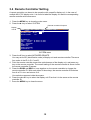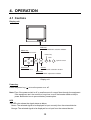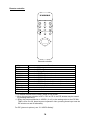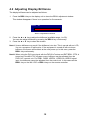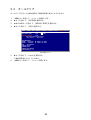
1
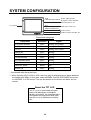
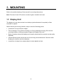
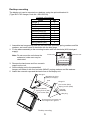
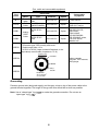
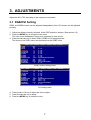
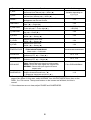
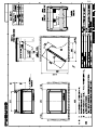
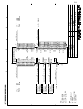
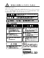
(Elemental Chlorine Free)
The paper used in this manual
is elemental chlorine free.
Printed in Japan
PUB.NO. OMC-20340-A1
(0603,YOSH) MU-170C
MU-170C
OPERATOR'S MANUAL
MU-170C OPERATOR'S MANUAL
MU-170C
Multi-purpose LCD Display
IMPORTANT NOTICE
•
No part of this manual may be copied or reproduced without written permission.
•
If this manual is lost or worn, contact your dealer about replacement.
•
The contents of this manual and equipment specifications are subject to change without
notice.
•
The example screens (or illustrations) shown in this manual may not match the screens
you see on your display. The screen you see depends on your system configuration and
equipment settings.
•
This manual is intended for use by native speakers of English.
•
FURUNO will assume no responsibility for the damage caused by improper use or
modification of the equipment or claims of loss of profit by a third party.
•
Please carefully read and follow the operation and maintenance procedures set forth in
this manual.
•
Store this manual in a convenient place for further reference.
SAFETY INSTRUCTIONS
Safety Instructions for the Installer
Safety Instructions for the Operator
WARNING
WARNING
Do not open the equipment.
Only qualified personnel
should work inside
the equipment.
Do not open the cover
unless totally familiar with
electrical circuits and
service manual.
Do not disassemble or modify the
equipment.
Improper handling can result
in electrical shock.
Fire, electrical shock or serious injury can
result.
Turn off the power at the switchboard
before beginning the installation.
Use the proper fuse and power cable.
Fire or electrical shock can result if the
power is left on.
Fuse rating is shown on the equipment.
Use of a wrong fuse can result in damage
to the equipment.
Do not install the equipment where it
may get wet from rain or water splash.
Immediately turn off the power at the
switchboard if the equipment is emitting
smoke or fire.
Water in the equipment can result in fire,
electrical shock or damage to the
equipment.
Continued use of the equipment can cause
fire or electrical shock. Contact a FURUNO
agent for service.
CAUTION
Do not place any object near the
exhaust or intake vent.
Observe the following compass safe
distances to prevent interference to a
magnetic compass:
Fire may result.
Standard
compass
CAUTION
Do not connect/disconnect the signal
cable while turning the power on.
Steering
compass
LCD Monitor MU-170C
0.5 m
0.3 m
Remote Controller
RMC-200
0.3 m
0.3 m
The unit may be damaged.
When lifting the display unit, hold it
together with the hard cover.
A warning label is attached to the
equipment. Do not remove the label.
If the label is missing or damaged,
contact a FURUNO agent or dealer.
Grasping by the hard cover alone may
allow the display unit to fall, resulting in
possible bodily injury or damage to the
equipment.
WARNING
To avoid electrical shock, do not
remove cover. No user-serviceable
parts inside.
Name: Warning Label (1)
Type: 86-003-1011-1
Code No.: 100-236-231
i
TABLE OF CONTENTS
FOREWORD ........................................................................................................ iii
SYSTEM CONFIGURATION................................................................................ iv
EQUIPMENT LISTS .............................................................................................. v
1. MOUNTING ....................................................................................................... 1
1.1 Display Unit..................................................................................................................... 1
1.2 Remote Controller ........................................................................................................... 4
2. WIRING ............................................................................................................. 5
3. ADJUSTMENTS ................................................................................................ 7
3.1 RGB/DVI Setting ............................................................................................................. 7
3.2 VIDEO Setting................................................................................................................. 9
3.3 Menu Window Setting ................................................................................................... 10
3.3.1 Adjusting the menu window................................................................................ 10
3.3.2 Changing the signal name.................................................................................. 11
3.4 Remote Controller Setting ............................................................................................. 12
4. OPERATION.................................................................................................... 13
4.1 Controls......................................................................................................................... 13
4.2 Adjusting Display Brilliance............................................................................................ 15
4.3 Choosing Source for Main Picture ................................................................................. 16
4.4 Choosing Source for Picture-in-Picture.......................................................................... 17
5. MAINTENANCE, TROUBLESHOOTING ....................................................... 18
5.1 Maintenance.................................................................................................................. 18
5.2 Troubleshooting............................................................................................................. 19
5.3 Clearing the Memory ..................................................................................................... 20
SPECIFICATIONS........................................................................................... SP-1
Declaration of Conformity
PACKING LISTS ............................................................................................... A-1
OUTLINE DRAWINGS ...................................................................................... D-1
INTERCONNECTION DIAGRAM ......................................................................S-1
ii
FOREWORD
A Word to the Owner of the MU-170C
FURUNO Electric Company thanks you for purchasing the MU-170C 17” Multi-Purpose
LCD Display. We are confident you will discover why the FURUNO name has become
synonymous with quality and reliability.
For over 50 years FURUNO Electric Company has enjoyed an enviable reputation for
quality and reliability throughout the world. This dedication to excellence is furthered by our
extensive global network of agents and dealers.
Your equipment is designed and constructed to meet the rigorous demands of the marine
environment. However, no machine can perform its intended function unless properly
installed and maintained. Please carefully read and follow the operation, installation and
maintenance procedures set forth in this manual.
We would appreciate feedback from you, the end-user, about whether we are achieving our
purposes.
Thank you for considering and purchasing FURUNO.
Features
• Main or remote display for radars, video sounders, sonars, plotter. Compatible
equipment: FAR-21X7 series, NavNet vx2, FCV-1200L/1200LM, CH-250, CH-270,
CSH-5L/8L, GD-280/380/680, etc.
• High resolution display of 1280 x 1024 dot (SXGA)
• Brightness of 1000 cd/m2 (maximum) and 2 cd/m2 or less (minimum) for comfortable
viewing day and night
• Landscape orientation
• Picture-in-picture function
iii
SYSTEM CONFIGURATION
RGB
Radar, Video Plotter,
Navigator, Video Sounder,
Scanning Sonar, etc.
DVI
12-24 VDC
FAR-21X7 series, etc.
VIDEO (NTSC/PAL)
CCD camera,
Video cassette recorder, etc.
Connectable equipment
Equipment
Resolution
Signal
FCV-1200L/1200LM*
VGA**
Analog, via IF-8000
CH-250
VGA**
Analog, via IF-8000
CH-270
VGA**
Analog, via IF-8000
CSH-5L/8L
XGA**
Analog
FSV-24/24S
SXGA
Analog
GD-280/380/680
VGA**
Analog
FR-1500 MK3 series
XGA**
Analog
FR-21X5 series
SXGA
Analog
FAR-21X7 series
SXGA
DVI
NavNet vx2
VGA**
Analog
*: Not useable with the portrait type.
**: When inputting VGA, SVGA or XGA, the circle may be displayed as an ellipse because
the aspect ratio differs. In this case, select NORMAL from the DISP MODE menu item
on the RGB1, 2 or DVI menus. The top and bottom on the screen are blank, but it is
normal.
About the TFT LCD
The TFT LCD is constructed using the
latest LCD techniques, and displays
99.99% of its pixels. The remaining 0.01%
of the pixels may drop out or blink, however this is not an indication of malfunction.
iv
EQUIPMENT LISTS
Standard supply
Name
Type
Code No.
Qty
Display Unit
MU-170C
-
1
Remote Controller Set*
RMC-200
000-012-629
1 set
Spare Parts*
SP19-00401
001-416-700
1 set
Installation Materials*
CP19-00500
000-012-654
1 set
Accessories*
FP19-01001
001-416-740
1 set
Remarks
w/hard cover
*: See packing list of this manual.
Option
Name
Code No.
Qty
3COX-2P-6C 5M
000-146-500
1
Cable length: 5 m
3COX-2P-6C 10M
000-146-501
1
Cable length: 10 m
DVI-D/D SINGLELINK5M
000-149-054
1
Cable length: 5 m
Bracket kit
for Monitor
MU-170C Hanger
000-153-819
1 set
Remote
Controller
Set
RMC-200
000-012-629
1 set
Cable Assy
Type
v
Remarks
See page 3.
1. MOUNTING
Refer to the outline drawing of this manual for mounting dimensions.
Note: The face of the LCD monitor is made of glass. Handle it with care.
1.1 Display Unit
The display unit may be mounted on a desktop (optional bracket kit required) or flush
mounted in a panel.
When selecting a mounting location, keep in mind the following points:
• Locate the unit out of direct sunlight.
• The unit weighs 7.5 kg (flush mounting) or 12.9 kg (desktop mounting). Be sure the
mounting location is strong enough to support the weight of the unit.
• Select a location where the display can be easily viewed and the controls can be easily
operated.
• Leave sufficient space around the unit for servicing and maintenance. See the outline
drawing for minimum service clearance.
• Locate the unit away from areas subject to water splash and rain.
1
Flush mounting
See the outline drawing of this manual for mounting dimensions.
CAUTION
Hold the hard cover and display unit
together when lifting the display unit.
The display unit may fall out if only the
hard cover is held.
1. Remove the hard cover and four cosmetic caps from the unit.
2. Using the paper template supplied, make a cutout in the mounting location.
3. Set the display unit to the cutout, and fasten it with four self-tapping screws (5x40,
supplied as accessories).
Note: Hex head bolts may also be used to fasten the display unit. However, their
lengths must project 10 mm from the wall.
Waterproofing: IP56, CFR46
Waterproofing: IP20
Cosmetic cap
Minimum: 50
30
98
Flush mounting
4. Attach the cosmetic caps and the hard cover to the display unit.
2
Desktop mounting
The display unit can be mounted on a desktop, using the optional bracket kit
(Type: MU-170C Hanger, Code No.: 000-153-819).
Contents of bracket kit
Name
Hanger L
Hanger R
Pole
Hole plug
Hex bolt (M10x30)
Flat washer (M10)
Spring washer (M10)
Hex bolt (M5x25)
Flat washer (M5)
Spring washer (M5)
Qty
1
1
1
2
2
2
2
4
4
4
1. Assemble two hangers and pole with two hex bolts (M10x30), spring washers and flat
washers, and cover holes for hex bolts with the hole plugs.
2. Fix the above assembly to the mounting location with four hex bolts (M10, dockyard
supply).
Intake vent
Note: Do not mount the unit where the
exhaust or intake vent may be
obstructed.
Exhaust vent
3. Remove the hard cover and four cosmetic
caps from the unit.
Display unit (rear view)
4. Set the display unit to the assembled
hanger, and fasten it with four hex bolts (M5x25), spring washers and flat washers.
5. Attach the cosmetic caps and the hard cover to the display unit.
Hanger L
M10 bolts for fixing
(Dockyard supply)
Pole
Hanger R
Flat washer (M10)
Spring washer (M10)
Hex bolt (M5x25)
Spring washer (M5)
Flat washer (M5)
Hex bolt
(M10x30)
Hole plug
To remove this cosmetic cap,
insert fingernail in groove.
Desktop mounting
3
1.2 Remote Controller
Setting battery
1. Open the back cover of the remote controller and set two batteries supplied.
WARNING
Ensure battery polarity is correct.
Wrong polarity may cause the batteries
to explode.
2. Close the back cover of the remote controller.
Writing the device name on the label
Write the device name (ex. “FCV-1200L”) for each “signal” name on the label supplied with
the remote controller. Attach the label to the remote controller at the location shown below.
RGB1
RGB2
DVI
VIDEO1
VIDEO2
VIDEO3
PIP1
PIP2
PIP3
+
MENU
BRILL
RGB 1 : FCV-1200L
RGB2 :
DVI : FAR-21X7 series
VIDEO1: CCD camera
VIDEO2:
VIDEO3:
Label
Remote controller RMC-200
4
2. WIRING
Connect external equipment to the MU-170C by referring to the drawing below, the table on
the next page and the interconnection diagram in this manual.
Note: The MU-170C does not have a “hot plug” function. Therefore, when the power switch
of the MU-170C and the equipment connected to it are on, do not connect or
disconnect the interconnection cable to prevent damage to equipment.
( )(+)
Fuse
Blue Red
VIDEO3
TB-1
14AWG-2C-PVC *5M*
(Supplied)
VIDEO2
CCD camera,
Video cassette
recorder, etc.
VIDEO1
12-24 VDC
Ground terminal
2.5C2V or 3C2V
(Local supply)
DVI-D
DVI-D/D SINGLELINK5M
(Option)
FCV-1200L/1200LM
CH-250
CH-270
CSH-5L/8L
FSV-24/24S
GD-280/380/680
FR-1500 MK3 series
FR-21X5 series
NavNet vx2
RGB2
RGB1
3COX-2P-6C (Option)
Display unit (bottom view)
5
FAR-21X7 series
Port, cable and connectable equipment
Used cable
Port
Name
TB-1
DVI-D
RGB1
VIDEO1
000-154-337
Standard
000-149-054
Option
3COX-2P-6C
5M
000-146-500
Option
3COX-2P-6C
10M
000-146-501
Option
Name
Type
Power
cable
DVI
Cable
14AWG-2C-PVC
*5M*
DVI-D/D
SINGLELINK5M
Analog
RGB
Cable
RGB2
Code No.
Standard/
Option
Connectable
Equipment
Power source
PC,
FAR-21X7 series
FCV-1200L/1200LM,
CH-250, CH-270,
CSH-5L/8L,
FSV-24/24S,
GD-280/380/680,
FR-1500 MK3 series,
FR-21X5 series,
NavNet vx2
Prepare the following cable locally.
▪ Connector type: RCA (metal), both ends
▪ Cable length: Max. 10 m
▪ 2.5C2V or 3C2V (Japan Industrial Standard, or the
equivalent) coaxial cable (Impedance: 75 Ω)
Cable 3C2V
Insulator
Video cassette
recorder, CCD camera,
DVD player
VIDEO2
Shield
VIDEO3
Vinyl
sheath
Conductor 2
S = 0.19 mm
∅ = 0.5 mm
Grounding
Fasten a ground wire (dockyard supply) and the gray crimp-on lug of the power cable to the
ground terminal together. The length of the ground wire should be as short as possible.
Note: Use a “closed-type” lug (
).
“open-type” lug (
) to make the ground connection. Do not use an
6
3. ADJUSTMENTS
Adjust the MU-170C according to the equipment connected.
3.1 RGB/DVI Setting
RGB1 and RGB2 screens can be adjusted independently. Also, DVI screen can be adjusted
similarly.
1. Adjust the display currently selected, at the DISP selection window. (See section 4.3.)
2. Press the MENU key to show the main menu.
The main menu disappears if there is no operation for one minute.
3. Press the ◄ or ► key to select RGB1, RGB2 or DVI as appropriate.
The items on the RGB1 menu are duplicated on the RGB2 menu.
RGB1
RGB2
H_SIZE
V_SIZE
PHASE
CONTRAST
H_POSITION
V_POSITION
R_LEVEL
G_LEVEL
B_LEVEL
TEMPERATURE
B STRETCH
W STRETCH
DISP MODE
SHARPNESS
DVI
VIDEO1
640
480
16
44
50
25
31
31
31
7000K
OFF
OFF
FULL
5
VIDEO2
VIDEO3
OSD
SYSTEM
(1 – 32)
(1 – 64)
(1 – 99)
(1 – 40)
(1 – 64)
(1 – 64)
(1 – 64)
(5500K/6500K/7000K/8000K)
(OFF, 1 – 10)
(OFF, 1 – 10)
(FULL/EVEN/NORMAL)
(1 – 10)
RGB1 (RGB2) setting menu
RGB1
RGB2
CONTRAST
H_POSITION
V_POSITION
R_LEVEL
G_LEVEL
B_LEVEL
TEMPERATURE
B STRETCH
W STRETCH
DISP MODE
SHARPNESS
DVI
VIDEO1
44
25
25
31
31
31
7000K
OFF
OFF
FULL
5
VIDEO2
VIDEO3
OSD
(1 – 64)
(1 – 50)
(1 – 40)
(1 – 64)
(1 – 64)
(1 – 64)
(5500K/6500K/7000K/8000K)
(OFF, 1 – 10)
(OFF, 1 – 10)
(FULL/EVEN/NORMAL)
(1 – 10)
DVI setting menu
4. Press the ▲ or ▼ key to select the item to adjust.
5. Press the ◄ or ► key to adjust.
6. Press the MENU key to close the menu.
7
SYSTEM
Menu item
Function
Available range
Adjusts the image size horizontally.
H_SIZE
Horizontal size: Narrow (◄) ↔ Wide (►)
Variable depending on
signal type
Adjusts the image size vertically.
V_SIZE
Vertical size: Narrow (◄) ↔ Wide (►)
Adjusts the timing of sampling so that the flicker
PHASE**
1-32
disappears and the text is clear.
Increases or decreases contrast level.
CONTRAST
1-64
Dark (◄) ↔ Bright (►)
Moves the image position horizontally.
1-99 (RGB1, 2),
H_POSITION
To the left (◄) ↔ To the right (►)
1-50 (DVI)
Moves the image position vertically.
V_POSITION
1-40
Up (◄) ↔ Down (►)
Adjusts red color level.
R_LEVEL
1-64
Weak (◄) ↔ Strong (►)
Adjusts green color level.
G_LEVEL
1-64
Weak (◄) ↔ Strong (►)
Adjusts blue color level.
B_LEVEL
1-64
Weak (◄) ↔ Strong (►)
Adjusts color temperature.
TEMPERATURE
5500K/6500K/7000K/8000K
5500K/6500K/7000K/8000K
Warm color ↔ Cold color
Emphasizes black color.
B STRETCH
OFF, 1-10
Standard (OFF, ◄) ↔ Dark (►)
Emphasizes white color.
W STRETCH
OFF, 1-10
Standard (OFF, ◄) ↔ Bright (►)
Selects the signal resolution.
FULL: Shows the input signal on entire screen.
DISP MODE
EVEN: Shows the input signal with original size.
FULL/EVEN/NORMAL*
NORMAL: Shows the input signal with same
aspect ratio.
Sharpens the edge horizontally.
SHARPNESS**
1-10
Softens characters and lines. (◄)
↔ Sharpens characters and lines. (►)
*: When inputting VGA, SVGA or XGA, a circle may be displayed as an ellipse because the
aspect ratio differs. In this case, select NORMAL from the DISP MODE menu item on the
RGB1, 2 or DVI menus. The top and bottom on the screen are left blank, but this is
normal.
**: If the characters are not clear, adjust PHASE and SHARPNESS.
8
3.2 VIDEO Setting
VIDEO1, VIDEO2 and VIDEO3 screens can be adjusted independently. The
picture-in-picture window for each can be adjusted similarly. Also, the size of the
picture-in-picture window can be adjusted at VIDEO1 (2 or 3) setting menu.
Picture-in-picture window
Picture-in-picture window
1. Set to the display currently selected, at the DISP selection window. (See section 4.3.)
2. Press the MENU key to show the main menu.
3. Press the ◄ or ► key to select VIDEO1, VIDEO2 or VIDEO3 as appropriate.
Same items are contained on VIDEO1, VIDEO2 and VIDEO3 setting menus.
RGB1
RGB2
PIP_SIZE
CONTRAST
R_LEVEL
G_LEVEL
B_LEVEL
TEMPERATURE
B STRETCH
W STRETCH
DVI
VIDEO1
5
44
31
31
31
7000K
OFF
OFF
VIDEO2
VIDEO3
OSD
SYSTEM
(1 – 10)
(1 – 64)
(1 – 64)
(1 – 64)
(1 – 64)
(5500K/6500K/7000K/8000K)
(OFF, 1 – 10)
(OFF, 1 – 10)
VIDEO1 (2 or 3) setting menu
4. Press the ▲ or ▼ key to select the item to set.
5. Press the ◄ or ► key to adjust.
6. Press the MENU key to close the menu.
Menu item
PIP_SIZE
Function
Adjusts the size of picture-in-picture window.
CONTRAST
Increases or decreases contrast level.
R_LEVEL
Adjusts red color level.
G_LEVEL
Adjusts green color level.
B_LEVEL
Adjusts blue color level.
TEMPERATURE Adjusts color temperature.
B STRETCH
Emphasizes black color.
W STRETCH
Emphasizes white color.
(Refer to the table on page 8.)
9
Available range
1 (35 mm x 27 mm) 10 (237 mm x 189 mm)
1-64
1-64
1-64
1-64
5500K/6500K/7000K/8000K
OFF, 1-10
OFF, 1-10
3.3 Menu Window Setting
3.3.1 Adjusting the menu window
The menu window can be moved and translucentized on the OSD (On Screen Display)
menu.
1. Press the MENU key to show the main menu.
2. Press the ◄ or ► key to select OSD.
RGB1
RGB2
H_POSITION
V_POSITION
TRANSLUCENT
PIP SW TIME
PIP SKIP
DVI
VIDEO1
15
37
OFF
OFF
OFF
VIDEO2
VIDEO3
OSD
SYSTEM
(1 – 29)
(1 – 37)
(OFF/ON)
(OFF, 5-20)
(OFF, V1/V2/V3)
CUSTOM NAME
RGB1 = RGB1______
RGB2 = RGB2______
DVI
= DVI_______
VIDEO1 = VIDEO1____
VIDEO2 = VIDEO2____
VIDEO3 = VIDEO3____
OSD menu
3. Press the ▲ or ▼ key to select the item to set.
4. Press the ◄ or ► key to adjust.
5. Press the MENU key to close the menu.
Menu item
H_POSITION
V_POSITION
TRANSLUCENT
PIP SW TIME
PIP SKIP
CUSTOM NAME
Function
Moves the menu window horizontally.
To the left (◄) ↔ To the right (►)
Moves the menu window vertically.
Up (◄) ↔ Down (►)
Translucentizes the background color on the
menu window.
OFF: Blue
ON: Translucent
Switches the screen image on the PIP window
among VIDEO1, VIDEO2 and VIDEO3 at the
interval (5-20 sec) selected here.
OFF: This function is turned off.
Chooses which video signals to display in the
PIP window when PIP SW TIME is enabled.
OFF: VIDEO1, VIDEO2 and VIDEO3 are shown
in turn.
V1: VIDEO2 and VIDEO3 are shown alternately.
V2: VIDEO1 and VIDEO3 are shown alternately.
V3: VIDEO1 and VIDEO2 are shown alternately.
See the next section.
10
Available range
1-29
1-37
OFF, ON
OFF, 5-20
OFF, V1/V2/V3
3.3.2
Changing the signal name
You can change the signal name which is shown on the DISP selection window (page 16)
and PIP selection window (page 17). It is useful to use the name of the device connected
(ex. “FCV-1200L”).
1. Press the MENU key to show the main menu.
2. Press the ◄ or ► key to select OSD.
RGB1
Signal
name area
RGB2
H_POSITION
V_POSITION
TRANSLUCENT
PIP SW TIME
PIP SKIP
DVI
VIDEO1
15
37
OFF
OFF
OFF
VIDEO2
VIDEO3
OSD
SYSTEM
(1 – 29)
(1 – 37)
(OFF/ON)
(OFF, 5-20)
(OFF, V1/V2/V3)
CUSTOM NAME
RGB1 = RGB1______
RGB2 = RGB2______
DVI
= DVI_______
VIDEO1 = VIDEO1____
VIDEO2 = VIDEO2____
VIDEO3 = VIDEO3____
OSD menu
3. Press the ▲ or ▼ key to select the signal to change its name in the signal name area. In
the example above, RGB1 is chosen.
4. Press the ► key to select the character you want to change. In the example below, “G”
of RGB1 is selected.
CUSTOM NAME
RGB1 = RGB1______
RGB2 = RGB2______
DVI
= DVI________
VIDEO1 = VIDEO1____
VIDEO2 = VIDEO2____
VIDEO3 = VIDEO3____
5. Press the ▲ or ▼ key to select appropriate alphanumeric character. In the example
below, “5” is selected.
You can set up to ten characters. “A to Z”, “0 to 9”, “-”, “.”, “ ” (space) are available.
CUSTOM NAME
RGB1 = R5B1______
RGB2 = RGB2______
DVI
= DVI________
VIDEO1 = VIDEO1____
VIDEO2 = VIDEO2____
VIDEO3 = VIDEO3____
6. To change another signal name, press the ◄ key several times to return the cursor to
the signal name area and then press the ▲ or ▼ key to select signal name.
7. Press the MENU key to close the menu.
11
3.4 Remote Controller Setting
A remote controller can be set to be operative with a specific display unit, in the case of
multiple MU-170C display units. It is useful to label the display unit and the corresponding
remote controller with same name.
1. Press the MENU key to show the main menu.
2. Press the ► key to select SYSTEM.
Remote controller ID square
Display
unit ID
RGB1
RGB2
DVI
INFRARED REMOTE
EXT BRILL CTRL
DEFAULT RESET
VIDEO1
A
OFF
NO
VIDEO2
VIDEO3
OSD
SYSTEM
(OFF/ON)
INFORMATION
RGB1 : 1280x1024 fH: 80KHz
RGB2 : 640x480
fH: 31KHz
DVI
: NO SIGNAL
VIDEO1: NTSC
VIDEO2: PAL
VIDEO3: NO SIGNAL
PROGRAM NO.: *****
fV: 75Hz
fV: 60Hz
SYSTEM menu
3. Press the ▼ key to select INFRARED REMOTE.
You may set the ID (identification code) of display unit and remote controller. There are
four codes in the ID; A, B, C and D.
4. Point the remote controller toward the optical sensor of the display unit, and press any
key on the remote controller. The current setting of the remote controller is shown inside
the remote controller ID square.
5. Press the RGB2 and BRILL + keys together on the remote controller to change the
remote controller ID. With each press of those keys, the remote controller ID switches
from A to D in turn and returns to A.
Your selection appears inside the square.
6. Press the ◄ or ► key to select the display unit ID so that it is the same as the remote
controller ID.
7. Press the MENU key to close the menu.
12
4. OPERATION
4.1 Controls
Display unit
MENU key
Shows the main menu.
DISP key
Shows the DISPLAY selection window.
Power key
LED
Optical sensor
Arrow keys
Select menu item.
PIP key
Shows the PIP selection window.
BRILL key
Shows the BRILL adjustment window.
Display unit
Power key
Press the power key ( ) to turn the power on or off.
Note: Even if the power switch is off, a small amount of current flows through the equipment.
If the equipment won’t be used for a long time, turn off the breaker switch at ship’s
power distribution box to prevent battery consumption.
LED
The LED color shows the signal status as below.
Green: The selected signal to be displayed is input correctly from the external device.
Orange: The selected signal to be displayed is not input from the external device.
13
Remote controller
RGB1
RGB2
DVI
VIDEO1
VIDEO2
VIDEO3
PIP1
PIP2
PIP3
+
MENU
BRILL
Remote controller
Key name
Function
RGB1*
Shows the RGB1 signal.
RGB2*
Shows the RGB2 signal.
DVI*
Shows the DVI signal.
VIDEO1**
Shows the VIDEO1 signal on the entire screen.
VIDEO2**
Shows the VIDEO2 signal on the entire screen.
VIDEO3**
Shows the VIDEO3 signal on the entire screen.
PIP1***
Shows the VIDEO1 signal in the picture-in-picture window.
PIP2***
Shows the VIDEO2 signal in the picture-in-picture window.
PIP3***
Shows the VIDEO3 signal in the picture-in-picture window.
BRILL (-)
Decreases the display brilliance.
BRILL (+)
Increases the display brilliance.
MENU
Shows the main menu.
Arrow keys
Select the menu items.
*: PIP window remains on the RGB1, RGB2 or DVI screen.
**: When the previous selection is PIP1, PIP2 or PIP 3, the PIP window may be erased
by pressing these keys.
***: When the previous selection is VIDEO1 (2 or 3) or the setting value on the PIP SW
TIME is from 5 to 20, these keys are inoperative. Also, pressing these keys turns the
PIP window on and off alternately.
For PIP (picture-in-picture), see “3.2 VIDEO Setting”.
14
4.2 Adjusting Display Brilliance
The display brilliance can be adjusted as follows.
1. Press the BRILL key on the display unit to show the BRILL adjustment window.
This window disappears if there is no operation for five seconds.
BRILL 50
BRILL adjustment window
2. Press the ◄ or ► key to adjust the brilliance (available range: 1 to 50).
You can also adjust brilliance by pressing the BRILL key continuously.
3. Press the ▲ or ▼ key to close the window.
Note1: Uneven brilliance may result if the brilliance is too low. This is normal with an LCD;
it is not a symptom of malfunction. If the equipment is turned off with minimum
brilliance, the screen will be blank at the next power up. In this case, press the
BRILL key continuously.
Note2: When using the DVI input signal with the FAR-21x7 series and EXT BRILL CTRL is
turned on in the MU-170C’s system menu, brilliance can be adjusted from the
FAR-21x7’s control unit. For RGB1, RGB2, VIDEO1, VIDEO2 or VIDEO3 signal
input, the brilliance cannot be adjusted from the control unit. In this case use the
BRILL key on the MU-170C or BRILL keys on the remote controller.
15
4.3 Choosing Source for Main Picture
Choose the signal to display on the entire screen as follows:
1. Press the DISP key to show the DISP selection window.
This window disappears if there is no operation for five seconds.
RGB1
RGB2
DVI
VIDEO1
VIDEO2
VIDEO3
DISP selection window
2. Press the ▲ or ▼ key to select a signal.
You can also select the signal by pressing the DISP key continuously.
RGB1-2:
The signal from the chosen RGB port is displayed.
DVI:
The signal from the DVI port is displayed.
VIDEO1-3: The external video from the chosen VIDEO port is displayed on the
entire screen.
3. Press the ◄ or ► key to close the window.
The window disappears if there is no operation within five seconds.
Note: The name of the selected signal appears at the right top corner for five seconds after
the DISP selection window is erased.
16
4.4 Choosing Source for Picture-in-Picture
Choose the source for the picture-in-picture window as follows:
Note1: The screen image on the picture-in-picture window can be switched automatically
among VIDEO1, VIDEO2 and VIDEO3 at the interval specified. Set the PIP SW
TIME on the OSD menu. For details, see “3.3.1 Adjusting the menu window”.
Note2: The size of the picture-in-picture window can be adjusted on the VIDEO1, 2 and 3
menus. For details, see “3.2 VIDEO Setting”.
1. With the RGB1, RGB2 or DVI display shown, press the PIP key.
The PIP selection window appears. This window disappears if there is no operation for
five seconds.
VIDEO1
VIDEO2
VIDEO3
OFF
PIP selection window
2. Press the ▲ or ▼ key to select the VIDEO port desired.
VIDEO can also be selected by pressing the PIP key continuously. To turn off the
picture-in-picture window, choose OFF.
3. Press the ◄ or ► key to close the window.
Note: The picture-in-picture window can be moved by pressing the arrow keys when menu
windows are closed.
17
5. MAINTENANCE,
TROUBLESHOOTING
WARNING
ELECTRICAL SHOCK HAZARD
Do not open the equipment.
Only qualified personnel
should work inside the
equipment.
5.1 Maintenance
Routine maintenance
Regular maintenance is important for good performance. Check the following on a regular
basis to keep the equipment in good operating condition.
• Check that the connectors at the bottom of the display unit are tightly fastened.
• Check the ground wire and ground terminal for rust. Clean if necessary. Confirm that the
ground wire is tightly fastened.
• Remove dust and dirt from the display unit and LCD with a dry, soft cloth. Do not use
chemical cleaners to clean any part of the display unit – they can remove paint and
markings.
• Wipe the LCD carefully to prevent scratching, using tissue paper and an LCD cleaner. To
remove dirt or salt deposits, use an LCD cleaner, wiping slowly with tissue paper so as
to dissolve the dirt or salt. Change paper frequently so the salt or dirt will not scratch the
LCD. Do not use solvents such as thinner, acetone or benzene for cleaning.
• Clean the filter at the intake vent regularly. To remove the filter, grasp the intake vent
with fingers and pull forward. Use an air blower to remove dust and dirt from the filter. If
it is particularly dirty, wash it in water or mild detergent and then let it dry. When
reattaching the filter, be sure the filters are correctly set to the holes for the intake vent.
Intake vent
Display unit, rear view
18
Fuse replacement
The fuse in the fuse holder protects the equipment from internal fault. If the fuse blows, find
the cause before replacing it. If the fuse blows again after replacement, request service.
WARNING
Use the proper fuse.
Use of a wrong fuse can cause fire or
damage to the equipment.
Ship’s power source
Rating of fuse
12 VDC
10 A
24 VDC
5A
Battery replacement
The remote controller has two AA
batteries. If the distance from which the
remote controller can be operated has
decreased, change the batteries.
WARNING
Ensure battery polarity is correct.
Wrong polarity may cause the batteries
to explode.
Note: Use the two AA batteries. Replace
all batteries together. Do not mix
old and new batteries.
Dispose of used batteries as industrial
waste. Follow the appropriate regulations
for the disposal of industrial waste.
LCD replacement
The life of the LCD is about 40,000 hours. When the brilliance cannot be raised sufficiently,
replace the LCD.
5.2 Troubleshooting
The table below provides troubleshooting procedures to use when no picture appears. If
you cannot restore the picture, do not attempt to check inside the equipment – there are no
user serviceable parts inside. Refer any work to a qualified technician.
Troubleshooting table
Reason for no picture
Remedy
Ship’s battery voltage too high.
Check battery voltage.
Fuse has blown.
Replace fuse.
Cable between MU-170C and external
equipment has loosened.
Refasten cable. You can
confirm which signals are
currently input in the
SYSTEM menu (see the
figure on the next page).
Power cable has loosened from the
terminal board.
Refasten cable.
19
5.3 Clearing the Memory
You may want to clear the memory to start afresh with default settings. You can do this as
follows:
1.
2.
3.
4.
Press the MENU key to show the main menu.
Press the ► key to open the SYSTEM menu.
Select DEFAULT RESET by arrow keys.
Press the ► key to select YES.
RGB1
RGB2
DVI
VIDEO1
VIDEO2
VIDEO3
A
A
INFRARED REMOTE
EXT BRILL CTRL
OFF
(OFF/ON)
DEFAULT RESET
YES
All custom settings will be lost.
←key: cancel
→key: reset
INFORMATION
RGB1 : 1280x1024 fH: 80KHz
RGB2 : 640x480
fH: 31KHz
DVI
: NO SIGNAL
VIDEO1: NTSC
VIDEO2: PAL
VIDEO3: NO SIGNAL
PROGRAM NO. : *****
fV: 75Hz
fV: 60Hz
SYSTEM menu
5. Press the ► key again to select “reset”.
6. Press the MENU key to close the menu.
20
OSD
SYSTEM
FURUNO
MU-170C
SPECIFICATIONS OF MULTI-PURPOSE LCD DISPLAY
MU-170C
1
GENERAL
1.1
Display
17-inch SXGA color TFT-LCD, 338 x 270 mm
1.2
Brightness
maximum: 1000 cd/m 2 , minimum: 2 cd/m 2 or less
1.3
Resolution
1280 x 1024 (SXGA)
1.4
Viewing Angle
up/down: 75°, left/right: 80°
1.5
Input Signal
RGB ports
2 ports, VESA (VGA, SVGA, XGA, SXGA),
(0.7 Vp-p, Synchronization: TTL level)
2
DVI port
1 port, VESA (VGA, SVGA, XGA, SXGA)
VIDEO ports
3 ports, NTSC/PAL, 0.7 Vp-p (75 Ω)
POWER SUPPLY
12-24 VDC: 6.0-3.0 A
3
ENVIRONMENTAL CONDITION
3.1
Ambient Temperature
Display Unit
-15°C to +55°C
Remote Controller
+5°C to +35°C
3.2
Relative Humidity
93% at +40°C
3.3
Waterproofing (IEC60529)
3.4
Display Unit
Front panel: IP56, CFR46, Rear panel: IP20
Remote Controller
IPX0
Vibration
● 2-5 Hz and up to 13.2 Hz with an excursion of ±1 mm ±10 %
(IEC 60945 ed.4)
(7 m/s2 maximum acceleration at 13.2 Hz)
● 13.2-100 Hz with a constant maximum acceleration of 7 m/s2
4
COATING COLOR
N3.0 (Not changed)
SP - 1
E2034S01B
FURUNO ELECTRIC CO., LTD.
9-52 Ashihara-Cho, Nishinomiya City, 662-8580, Hyogo, Japan
Tel: +81 798-65-2111 Fax: +81 798-65-4200
Pub NO. DOC-853
EC Declaration of Conformity
We
FURUNO ELECTRIC CO., LTD.
----------------------------------------------------------------------------------------------------------------------(Manufacturer)
9-52 Ashihara-Cho, Nishinomiya City, 662-8580, Hyogo, Japan
----------------------------------------------------------------------------------------------------------------------(Address)
declare under our sole responsibility that the product
Multi-purpose LCD display Type MU-170C
----------------------------------------------------------------------------------------------------------------------(Model name, serial number)
to which this declaration relates is in conformity with the following standard(s) or other normative
document(s)
EN 60945: 1997-01 (IEC 60945 Third edition: 1996-11) – Clauses 10.2 and 10.3
IEC 60945 Fourth edition: 2002-08 – Clauses 9.2, 9.3, 10.3, 10.4, 10.5, 10.8 and 10.9
----------------------------------------------------------------------------------------------------------------------(title and/or number and date of issue of the standard(s) or other normative document(s))
For assessment, see
• EMC Test Report FLI 12-05-052 of 25 November 2005 prepared by Furuno Labotech
International Co., Ltd.
This declaration is issued according to the Council Directive of 3 May 1989 on the approximation of
the laws of the Member States relating to electromagnetic compatibility (89/336/EEC).
On behalf of Furuno Electric Co., Ltd.
Nishinomiya City, Japan
November 25, 2005
---------------------------------------------(Place and date of issue)
Hiroaki Komatsu
Manager,
International Rules and Regulations
-----------------------------------------------------------------(name and signature or equivalent marking of authorized person)
A-1
A-2
A-3
D-1
D-2
S-1
FURUNO
MU-170C
►
▲
▼
►
RGB1
RGB2
DVI
VIDEO1
VIDEO2
A
A
INFRARED REMOTE
EXT BRILL CTRL
OFF
(OFF/ON)
DEFAULT RESET
YES
All custom settings will be lost.
←key: cancel
→key: reset
INFORMATION
RGB1 : 1280x1024 fH: 80KHz
RGB2 : 640x480
fH: 31KHz
DVI
: NO SIGNAL
VIDEO1: NTSC
VIDEO2: PAL
VIDEO3: NO SIGNAL
PROGRAM NO.: *****
fV: 75Hz
fV: 60Hz
►
21
VIDEO3
OSD
SYSTEM
•
20
•
•
•
•
19
VIDEO1
VIDEO2
VIDEO3
OFF
PIP
▲
▼
◄
►
18
RGB1
RGB2
DVI
VIDEO1
VIDEO2
VIDEO3
▲
▼
◄
►
17
BRILL 50
◄
►
▲
▼
16
RGB1
RGB2
DVI
VIDEO1
VIDEO2
VIDEO3
PIP1
PIP2
PIP3
+
MENU
BRILL
▲▼◄►
15
14
►
RGB1
RGB2
DVI
INFRARED REMOTE
EXT BRILL CTRL
DEFAULT RESET
VIDEO1
A
OFF
NO
VIDEO2
(OFF/ON)
INFORMATION
RGB1 : 1280x1024 fH: 80KHz
RGB2 : 640x480
fH: 31KHz
DVI
: NO SIGNAL
VIDEO1: NTSC
VIDEO2: PAL
VIDEO3: NO SIGNAL
PROGRAM NO.: *****
fV: 75Hz
fV: 60Hz
▼
◄
►
13
VIDEO3
OSD
SYSTEM
◄
►
RGB1
RGB2
H_POSITION
V_POSITION
TRANSLUCENT
PIP SW TIME
PIP SKIP
DVI
VIDEO1
15
37
OFF
OFF
OFF
VIDEO2
VIDEO3
(1 – 29)
(1 – 37)
(OFF/ON)
(OFF, 5 – 20)
(OFF, V1/V2/V3)
CUSTOM NAME
RGB1 = RGB1______
RGB2 = RGB2______
DVI
= DVI_______
VIDEO1 = VIDEO1____
VIDEO2 = VIDEO2____
VIDEO3 = VIDEO3____
►
CUSTOM NAME
RGB1 = RGB1______
RGB2 = RGB2______
DVI
= DVI________
VIDEO1 = VIDEO1____
VIDEO2 = VIDEO2____
VIDEO3 = VIDEO3____
▲
▼
CUSTOM NAME
RGB1 = R5B1______
RGB2 = RGB2______
DVI
= DVI________
VIDEO1 = VIDEO1____
VIDEO2 = VIDEO2____
VIDEO3 = VIDEO3____
◄
12
OSD
SYSTEM
◄
►
RGB1
RGB2
H_POSITION
V_POSITION
TRANSLUCENT
PIP SW TIME
PIP SKIP
DVI
VIDEO1
15
37
OFF
OFF
OFF
VIDEO2
(1 – 29)
(1 – 37)
(OFF/ON)
(OFF, 5 – 20)
(OFF, V1/V2/V3)
CUSTOM NAME
RGB1 = RGB1______
RGB2 = RGB2______
DVI
= DVI_______
VIDEO1 = VIDEO1____
VIDEO2 = VIDEO2____
VIDEO3 = VIDEO3____
▲
▼
◄
►
11
VIDEO3
OSD
SYSTEM
10
◄
►
RGB1
RGB2
PIP_SIZE
CONTRAST
R_LEVEL
G_LEVEL
B_LEVEL
TEMPERATURE
B STRETCH
W STRETCH
▲
▼
◄
►
DVI
VIDEO1
5
44
31
31
31
7000K
OFF
OFF
VIDEO2
VIDEO3
OSD
(1 – 10)
(1 – 64)
(1 – 64)
(1 – 64)
(1 – 64)
(5500K/6500K/7000K/8000K)
(OFF, 1 – 10)
(OFF, 1 – 10)
9
SYSTEM
8
◄
►
RGB1
RGB2
H_SIZE
V_SIZE
PHASE
CONTRAST
H_POSITION
V_POSITION
R_LEVEL
G_LEVEL
B_LEVEL
TEMPERATURE
B STRETCH
W STRETCH
DISP MODE
SHARPNESS
RGB1
RGB2
CONTRAST
H_POSITION
V_POSITION
R_LEVEL
G_LEVEL
B_LEVEL
TEMPERATURE
B STRETCH
W STRETCH
DISP MODE
SHARPNESS
▲
▼
◄
►
DVI
VIDEO1
640
480
16
44
50
25
31
31
31
7000K
OFF
OFF
FULL
5
DVI
VIDEO3
OSD
SYSTEM
(1 – 32)
(1 – 64)
(1 – 99)
(1 – 40)
(1 – 64)
(1 – 64)
(1 – 64)
(5500K/6500K/7000K/8000K)
(OFF, 1 – 10)
(OFF, 1 – 10)
(FULL/EVEN/NORMAL)
(1 – 10)
VIDEO1
44
25
25
31
31
31
7000K
OFF
OFF
FULL
5
VIDEO2
VIDEO2
VIDEO3
OSD
(1 – 64)
(1 – 50)
(1 – 40)
(1 – 64)
(1 – 64)
(1 – 64)
(5500K/6500K/7000K/8000K)
(OFF, 1 – 10)
(OFF, 1 – 10)
(FULL/EVEN/NORMAL)
(1 – 10)
7
SYSTEM
6
5
RGB1
RGB2
DVI
VIDEO1
VIDEO2
VIDEO3
PIP1
PIP2
PIP3
+
MENU
BRILL
RGB 1 : FCV-1200L
RGB2 :
DVI : FAR-21X7
VIDEO1: CCD
VIDEO2:
VIDEO3:
4
3
2
1
vi
v
iv
iii
ii
WARNING
To avoid electrical shock, do not
remove cover. No user-serviceable
parts inside.
i
•
•
•
•
•
•