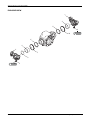
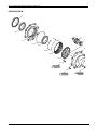
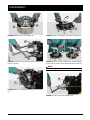
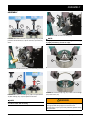
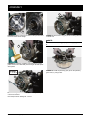
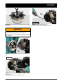
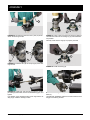
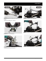
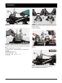
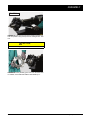
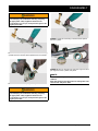
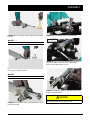
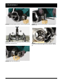
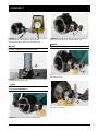
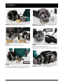
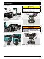
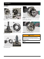
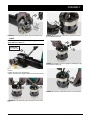
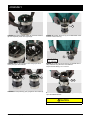
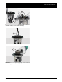
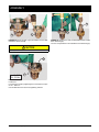
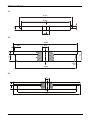
1
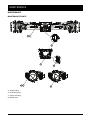
Service Manual Axle 725/539 725/540 ASM-0151E October 2012 CONTENTS INTRODUCTION ................................................................................................................................ 5 SPECIFICATIONS .............................................................................................................................. 6 DEFINITION OF VIEWPOINTS ................................................................................................................. 6 DATA PLATE ............................................................................................................................................ 6 CONVERSION TABLES ................................................................................................................................ 7 TORQUE SPECIFICATIONS ......................................................................................................................... 8 COARSE PITCH ....................................................................................................................................... 8 FINE PITCH .............................................................................................................................................. 8 WHEEL NUT TIGHTENING TORQUES .................................................................................................... 9 MAINTENANCE ............................................................................................................................................ 10 MAINTENANCE POINTS ......................................................................................................................... 10 MAINTENANCE INTERVALS ................................................................................................................... 11 ADJUSTMENT AND CHECKS ................................................................................................................. 11 LUBRICANT & SEALANT SPECIFICATIONS ........................................................................................... 12 SAFETY PRECAUTIONS ................................................................................................................... 13 SWINGING SUPPORT ....................................................................................................................... 15 EXPLODED VIEW .......................................................................................................................................... 15 DISASSEMBLY ............................................................................................................................................. 16 ASSEMBLY ................................................................................................................................................... 18 PLANETARY REDUCTION GEAR .................................................................................................... 21 EXPLODED VIEW .......................................................................................................................................... 21 DISASSEMBLY ............................................................................................................................................. 22 ASSEMBLY ................................................................................................................................................... 25 STEERING KNUCKLE ....................................................................................................................... 29 EXPLODED VIEW .......................................................................................................................................... 29 DISASSEMBLY ............................................................................................................................................. 30 ASSEMBLY ................................................................................................................................................... 33 STEERING CYLINDER ...................................................................................................................... 39 EXPLODED VIEW .......................................................................................................................................... 39 DISASSEMBLY ............................................................................................................................................. 40 ASSEMBLY ................................................................................................................................................... 42 BEVEL PINION ................................................................................................................................... 47 EXPLODED VIEW .......................................................................................................................................... 47 DISASSEMBLY ............................................................................................................................................. 48 ASSEMBLY ................................................................................................................................................... 51 HYDROLOCK DIFFERENTIAL UNIT ................................................................................................ 57 EXPLODED VIEW .......................................................................................................................................... 57 DISASSEMBLY ............................................................................................................................................. 58 ASSEMBLY ................................................................................................................................................... 62 LIMITED SLIP DIFFERENTIAL UNIT ................................................................................................ 67 EXPLODED VIEW .......................................................................................................................................... 67 DISASSEMBLY ............................................................................................................................................. 68 ASSEMBLY ................................................................................................................................................... 70 SPECIAL TOOLS ............................................................................................................................... 73 T1 T2 T3 T4 T5 T6 T7 T8 T9 ............................................................................................................................................................. 73 ............................................................................................................................................................. 73 ............................................................................................................................................................. 73 ............................................................................................................................................................. 74 ............................................................................................................................................................. 75 ............................................................................................................................................................. 76 ............................................................................................................................................................. 77 ............................................................................................................................................................. 78 ............................................................................................................................................................. 79 ASM-0151 - 725/539 & 725/540 Axle Service Manual Dana Holding Corporation 3 4 Dana Holding Corporation ASM-0151 - 725/539 & 725/540 Axle Service Manual INTRODUCTION The efficiency and continued operation of mechanical units depend on constant, correct maintenance and also on efficient repair work, should there be a break-down or malfunction. The instructions contained in this manual have been based on a complete overhaul of the unit. However, it is up to the mechanic to decide whether or not it is necessary to assemble only individual components, when partial repair work is needed. The manual provides a quick and sure guide which, with the use of photographs and diagrams illustrating the various phases of the operations, allows accurate work to be performed.All the information needed for correct disassembly, checks and assembly of each individual component is set out below. In order to remove the differential unit from the vehicle, the manuals provided by the vehicle manufacturer should be consulted. In describing the following operations it is presumed that the unit has already been removed from the vehicle. IMPORTANT: In order to facilitate work and protect both working surfaces and operators, it is advisable to use pro- per equipment such as: trestles or supporting benches, plastic or copper hammers, appropriate levers, pullers and specific spanners or wrenches. Before going on to disassemble the parts and drain the oil, it is best to thoroughly clean the unit, removing any encrusted or accumulated grease. INTRODUCTORY REMARKS: All the disassembled mechanical units should be thoroughly cleaned with appropriate products and restored or replaced if damage, wear, cracking or seizing have occurred. In particular, thoroughly check the condition of all moving parts (bearings, gears, crown wheel and pinion, shafts) and sealing parts (o-rings, oil shields) which are subject to major stress and wear. In any case, it is advisable to replace the seals every time a component is overhauled or repaired. During assembly, the sealing rings must be lubricated on the sealing edge. In the case of the crown wheel and pinion, replacement of one component requires the replacement of the other one. During assembly, the prescribed pre-loading, backlash and torque of parts must be maintained. CLASSIFICATION: This manual classifies units according to part numbers. For a correct interpretation, classification is indicated as follows: = up to the part number = from the part number on When no classification is given, disassembly and assembly operations are the same for all versions. SPECIFIC EQUIPMENT AND SPARE PARTS: The drawings of all specific tools required for maintenance and repair work can be found at the end of this manual; spare parts may be ordered either from the vehicle manufacturer or directly from the Service Centers or Authorized Distributors of SPICER. ASM-0151 - 725/539 & 725/540 Axle Service Manual Dana Holding Corporation 5 SPECIFICATIONS DEFINITION OF VIEWPOINTS DATA PLATE SPICER MODEL RATIO 1 DIFF. 3 SERIAL N° 4 AXLE N° 5 2 MFG. BY DANA ITALIA S.p.A. MADE IN COMO - ITALY 1 - Type and model unit - modification index 2 - Differential type 3 - Reduction ratio 4 - Serial number 5 - Axle number 6 Dana Holding Corporation ASM-0151 - 725/539 & 725/540 Axle Service Manual CONVERSION TABLES CONVERSION TABLES UNITS OF PRESSURE 1 ATM=1 BAR=105 PA=14.4 PSI UNIT OF WEIGHT N daN kN kg lbs 1N 1 0,1 0,001 0,102 0,225 1daN 10 1 0,01 1,02 2,25 1kN 1000 100 1 102 225 1kg 9,81 0,981 0,00981 1 2,205 UNITS OF TORQUE N·m daN·m kN·m kg·m lb·in 1N·m 1 0,1 0,001 0,102 8,854 1daN·m 10 1 0,01 1,02 88,54 1kN·m 1000 100 1 102 8854 1kg·m 9,81 0,981 0,00981 1 86,8 1 lb·in 0,1129 0,01129 0,0001129 0,01152 1 ASM-0151 - 725/539 & 725/540 Axle Service Manual Dana Holding Corporation 7 TORQUE SPECIFICATIONS TORQUE SPECIFICATIONS COARSE PITCH SIZE OF BOLT TYPE OF BOLT 8.8 8.8 + Loctite 270 10.9 10.9 + Loctite 270 12.9 12.9 + Loctite 270 M6 x 1 mm 9,5 – 10,5 N·m 10,5 – 11,5 N·m 14,3 – 15,7 N·m 15,2 – 16,8 N·m 16,2 – 17,8 N·m 18,1 – 20 N·m M8 x 1,25 mm 23,8 – 26,2 N·m 25,6 – 28,4 N·m 34,2 – 37,8 N·m 36,7 – 40,5 N·m 39 – 43 N·m 43,7 – 48,3 N·m M10 x 1,5 mm 48 – 53 N·m 52 – 58 N·m 68 – 75 N·m 73 – 81 N·m 80 – 88 N·m 88 – 97 N·m M12 x 1,75 mm 82 – 91 N·m 90 – 100 N·m 116 – 128 N·m 126 – 139 N·m 139 – 153 N·m 152 – 168 N·m M14 x 2 mm 129 – 143 N·m 143 – 158 N·m 182 – 202 N·m 200 – 221 N·m 221 – 244 N·m 238 – 263 N·m M16 x 2 mm 200 – 221 N·m 219 – 242 N·m 283 – 312 N·m 309 – 341 N·m 337 – 373 N·m 371 – 410 N·m M18 x 2,5 mm 276 – 305 N·m 299 – 331 N·m 390 – 431 N·m 428 – 473 N·m 466 – 515 N·m 509 – 562 N·m M20 x 2,5 mm 390 – 431 N·m 428 – 473 N·m 553 – 611 N·m 603 – 667 N·m 660 – 730 N·m 722 – 798 N·m M22 x 2,5 mm 523 – 578 N·m 575 – 635 N·m 746 – 824 N·m 817 – 903 N·m 893 – 987 N·m 974 – 1076 N·m M24 x 3 mm 675 – 746 N·m 732 – 809 N·m 950 – 1050 N·m 1040 – 1150 N·m 1140 – 1260 N·m 1240 – 1370 N·m M27 x 3 mm 998 – 1103 N·m 1088 – 1202 N·m 1411 – 1559 N·m 1539 – 1701 N·m 1710 – 1890 N·m 1838 – 2032 N·m M30 x 3,5 mm 1378 – 1523 N·m 1473 – 1628 N·m 1914 – 2115 N·m 2085 – 2305 N·m 2280 – 2520 N·m 2494 – 2757 N·m FINE PITCH SIZE OF BOLT TYPE OF BOLT 8.8 8.8 + Loctite 270 10.9 10.9 + Loctite 270 12.9 12.9 + Loctite 270 M8 x 1 mm 25,7 – 28,3 N·m 27,5 – 30,5 N·m 36,2 – 39,8 N·m 40 – 44 N·m 42,8 – 47,2 N·m 47,5 – 52,5 N·m M10 x 1,25 mm 49,4 – 54,6 N·m 55,2 – 61 N·m 71,5 – 78,5 N·m 78 – 86 N·m 86 – 94 N·m 93 – 103 N·m M12 x 1,25 mm 90 – 100 N·m 98 – 109 N·m 128 – 142 N·m 139 – 154 N·m 152 – 168 N·m 166 – 184 N·m M12 x 1,5 mm 86 – 95 N·m 94 – 104 N·m 120 – 132 N·m 133 – 147 N·m 143 – 158 N·m 159 – 175 N·m M14 x 1,5 mm 143 – 158 N·m 157 – 173 N·m 200 – 222 N·m 219 – 242 N·m 238 – 263 N·m 261 – 289 N·m M16 x 1,5 mm 214 – 236 N·m 233 – 257 N·m 302 – 334 N·m 333 – 368 N·m 361 – 399 N·m 394 – 436 N·m M18 x 1,5 mm 312 – 345 N·m 342 – 378 N·m 442 – 489 N·m 485 – 536 N·m 527 – 583 N·m 580 – 641 N·m M20 x 1,5 mm 437 – 483 N·m 475 – 525 N·m 613 – 677 N·m 674 – 745 N·m 736 – 814 N·m 808 – 893 N·m M22 x 1,5 mm 581 – 642 N·m 637 – 704 N·m 822 – 908 N·m 903 – 998 N·m 998 – 1103 N·m 1078 – 1191 N·m M24 x 2 mm 741 – 819 N·m 808 – 893 N·m 1045 – 1155 N·m 1140 – 1260 N·m 1235 – 1365 N·m 1363 – 1507 N·m M27 x 2 mm 1083 – 1197 N·m 1178 – 1302 N·m 1520 – 1680 N·m 1672 – 1848 N·m 1834 – 2027 N·m 2000 – 2210 N·m M30 x 2 mm 1511 – 1670 N·m 1648 – 1822 N·m 2138 – 2363 N·m 2332 – 2577 N·m 2565 – 2835 N·m 2788 – 3082 N·m 8 Dana Holding Corporation ASM-0151 - 725/539 & 725/540 Axle Service Manual TORQUE SPECIFICATIONS WHEEL NUT TIGHTENING TORQUES Wheel nut tightening torques recommended from rim's O.E.M. with reference to the quality of the rim's material. WHEEL NUT TIGHTENING TORQUES RECOMMENDED WHEEL NUTS TORQUE CHARACTERISTICS ILLUSTRATION WHEEL STUD THREAD RIM MATERIAL QUALITY ST 37 WHEEL NUTS WITH INTEGRATE SPHERICAL COLLAR FLAT COLLAR WHEEL NUTS WITH SEPARATE SPHERICAL LOCK WASHER WHEEL NUTS WITH INTEGRATE SEAT CAPTIVE WASHER **ST 52 M18 x 1,5 mm 330 N·m 460 N·m M20 x 1,5 mm 490 N·m 630 N·m M22 x 1,5 mm 630 N·m 740 N·m M18 x 1,5 mm 270 N·m 360 N·m M20 x 1,5 mm 360 N·m 450 N·m M22 x 1,5 mm 460 N·m 550 N·m M18 x 1,5 mm 260 N·m 360 N·m M20 x 1,5 mm 350 N·m 500 N·m M22 x 1,5 mm 450 N·m 650 N·m **RIM MATERIAL ST 52 IS RECOMMENDED BY DANA ON AXLE APPLICATIONS. IT IS THE OPTIMUM MATERIAL FOR TIGHTENING THE RIM TO THE HUB. NOTE: The wheel nut tightening torque is related only on nut thread and stud thread dry (without oil or any lubricant). NOTE: The wheel nut tightening torque takes into consideration not only the nut + stud characteristics, but also the quality of the rim material. THE DANA OFFICIAL TIGHTENING TORQUE TABLE, THAT IS INCLUDED IN EACH SERVICE MANUAL, SHOWS THE TORQUE FIGURE RELATED TO THE BOLT CHARACTERISTIC ONLY. DANA OFFICIAL TIGHTENING TORQUE TABLE NUT MATERIAL QUALITY 8.8 & 10.9 STUD MATERIAL QUALITY 10.9 *ALLOW TIGHT TORQUE M18 x 1,5 mm M18 x 1,5 N·m 442 ÷ 489 N·m M20 x 1,5 mm M20 x 1,5 N·m 613 ÷ 677 N·m M22 x 1,5 mm M22 x 1,5 N·m 822 ÷ 908 N·m *THE TORQUE FIGURE ON NUT AND STUD COUPLING MUST BE RELATED ON STUD MATERIAL QUALITY (DANA AXLES ARE 10.9 ONLY). ASM-0151 - 725/539 & 725/540 Axle Service Manual Dana Holding Corporation 9 MAINTENANCE MAINTENANCE MAINTENANCE POINTS 1 3 4 2 1 3 4 2 1 - Oil filling plug 2 - Oil draining plug 3 - Check level plug 4 - Grease zerk 10 Dana Holding Corporation ASM-0151 - 725/539 & 725/540 Axle Service Manual MAINTENANCE MAINTENANCE INTERVALS OPERATION FREQUENCY LUBRICANTS Differential Monthly Planetary reduction Every 200 hours Differential Every 1000/1200 hrs * Planetary reduction Every 1000/1200 hrs * Check levels SAE85W90 (API GL4 - MIL L-2105) With additives for oil-bath brakes Oil change It is recommended to set the axle's oil changes according to the machine maintenance intervals. If working in heavy conditions half intervals should be used. * Initially after 100 working hours OPERATION MEMBER Greasing Articulations CONDITIONS FREQUENCY Normal work Monthly Severe duty Weekly LUBRICANTS MOLIKOTE ADJUSTMENT AND CHECKS UNIT OPERATION FREQUENCY SERVICE BRAKE CIRCUIT Wheel nuts Tightening Every 200 hours** Only for mineral oil use e.g. ATF Dexron II. Make sure that master cylinder seals are suitable for mineral oil. ** Initially after 10 working hours ASM-0151 - 725/539 & 725/540 Axle Service Manual Dana Holding Corporation 11 MAINTENANCE LUBRICANT & SEALANT SPECIFICATIONS 1 - Locking, sealing and lubricating materials referred to in this manual are the same used in the shop-floor. 2 - The table below gives an account of the typical applications of each single material, in order to facilitate replacement with similar products marketed by different brand names with different trade marks. LOCTITE 242 Anaerobic product apt to prevent the loosening of screws, nuts and plugs. Used for medium-strength locking. Before using it, completely remove any lubricant by using the specific activator. LOCTITE 243 The oleocompatible alternative to 242. Does not require the activation of lubricated surfaces. LOCTITE 270 Anaerobic product for very-high strength locking of screws and nuts. Before using it, completely remove any lubricant by using the specific activator. To remove parts, it may be necessary to heat them at 80 °C approximately. LOCTITE 275 Anaerobic product suitable for high-strength locking and sealing of large threaded parts, bolts and stud bolts, for pipe sealing and for protecting parts against tampering; suitable for sealing coupling surfaces with a maximum diametrical clearance of 0.25 mm. LOCTITE 510 Anaerobic product for the hermetic sealing of flanged units and screw holes communicating with fluids. Can seal clearances between flanges up to 0.2 mm. LOCTITE 577 Quick anaerobic sealant for sealing threaded portions of conical or cylindrical unions up to M80. Before using it, remove any lubricant with the specific activator. After polymerisation, disassembly may result rather difficult, so heating may be necessary for larger diameters. LOCTITE 638 Anaerobic adhesive for fast and high-strength gluing of cylindrical metal joints (hub on shaft). Can glue together parts with clearance ranging between 0.1 and 0.25 mm. LOCTITE 648 Anaerobic adhesive for fast and medium-strength gluing of cylindrical metal joints (hub on shaft). Can glue together parts with radial clearance below 0.1 mm. AREXONS (REPOSITIONABLE JOINTING COMPOUND FOR SEALS) Solvent-based sealing compound for elastic seals, drying through evaporation. Used for sealing the outer diameter of sealing rings for rotating shafts with outer metal reinforcement. SILICONE Semi-fluid adhesive material used for sealing and filling and to protect components from environmental and physical elements. Polymerises with non-corrosive dampness. TECNO LUBE/101 (SILICONE-BASED GREASE) Highly adhesive synthetic grease, with silicone compounds added. Applied to adjustment screws with hole communicating with oil-type fluids. Used when frequent adjusting is required. MOLIKOTE (DOW CORNING) Lubricating compound containing molybdenum disulphide, used to lubricate articulation pins and to prevent sticking and oxidation of parts that are not lubricated on a regular basis. (LITHIUM-BASED) GREASE Applied to bearings, sliding parts and used to lubricate seals or parts during assembly. 12 Dana Holding Corporation ASM-0151 - 725/539 & 725/540 Axle Service Manual SAFETY PRECAUTIONS 1 - During all operations described in this manual, the axle should be fastened onto a trestle, while the other parts mentioned should rest on supporting benches. 2 - When removing one of the arms, an anti-tilting safety trestle should be placed under the other arm. 3 - When working on an arm that is fitted on the machine, make sure that the supporting trestles are correctly po- sitioned and that the machine is locked lengthways. 4 - Do not admit any other person inside the work area; mark off the area, hang warning signs and remove the igni- tion key from the machine. 5 - Use only clean, quality tools; discard all worn, damaged, lowquality or improvised wrenches and tools. Ensure that all torque wrenches have been checked and calibrated. 6 - Always wear gloves and non-slip rubber shoes when performing repair work. 7 - Should you stain a surface with oil, remove marks straight away. 8 - Dispose of all lubricants, seals, rags and solvents once work has been completed. Treat them as special waste and dispose of them according to the relative law provisions obtaining in the country where the axles are being overhauled. 9 - Make sure that only weak solvents are used for cleaning purposes; avoid using turpentine, dilutants and toluol, xylolbased or similar solvents; use light solvents such as Kerosene, mineral spirits or water-based, environment friendly solvents. 10 - For the sake of clarity, the parts that do not normally need to be removed have not been reproduced in some of the diagrams. 11 - After repair work has been completed, accurately touch up any coated part that may have been damaged. 12 - Follow all safety instructions in the Original Equipment Manufacturer (OEM) manual that came with the vehicle. ASM-0151 - 725/539 & 725/540 Axle Service Manual Dana Holding Corporation 13 MAINTENANCE 14 Dana Holding Corporation ASM-0151 - 725/539 & 725/540 Axle Service Manual SWINGING SUPPORT EXPLODED VIEW 7 9 11 8 10 5 - 8 N·m 6 4 1 5 3 5 - 8 N·m 2 ASM-0151 - 725/539 & 725/540 Axle Service Manual Dana Holding Corporation 15 DISASSEMBLY DISASSEMBLY FIGURE 4: Only if necessary, remove the grease zerk (2). FIGURE 1: Remove the swinging support (1) on the drive side. FIGURE 5: Using an extractor, remove the bushing (4) from the swinging support (1). FIGURE 2: Remove the shim washer (6) and the v-ring (5) FIGURE 6: Remove the swinging support (7) on the side opposite the drive. FIGURE 3: Use a screwdriver to remove the o-ring (3). 16 Dana Holding Corporation ASM-0151 - 725/539 & 725/540 Axle Service Manual DISASSEMBLY FIGURE 7: Remove the shim washer (11) and the v-ring (10). FIGURE 8: Only if necessary, remove the grease zerk (8). FIGURE 9: Using an extractor, remove the bushing (9) from the swinging support (7). ASM-0151 - 725/539 & 725/540 Axle Service Manual Dana Holding Corporation 17 ASSEMBLY ASSEMBLY FIGURE 13: Install the grease zerk (2) and tighten to a torque wrench setting of 5 - 8 N·m. FIGURE 10: Using tool T1 (See drawing T1 p. 73), mount the bushing (4) in the swinging support (1) on the pinion side. FIGURE 14: Install the v-ring (5) and the shim washer (6). FIGURE 11: The o-ring (3) housing should be mounted externally. NOTE: Lubricate with grease before installing. NOTE: The hole for the grease zerk on the bushing (4) is oriented towards grease zerk hole. FIGURE 15: Install the swinging support (1). FIGURE 12: Lubricate the o-ring (3) to hold in position and install it in the bushing. 18 Dana Holding Corporation NOTE: Check that it is properly oriented. Using a grease gun, lubricate the swinging support housing. ASM-0151 - 725/539 & 725/540 Axle Service Manual ASSEMBLY FIGURE 16: Make sure hole for the grease zerk on the bushing (9) should be oriented towards grease zerk hole. FIGURE 19: Install the grase zerk (8) and tighten to a torque wrench setting of 5 - 8 N·m. FIGURE 17: Using tool T1 (See drawing T1 p. 73), mount the bushing (9) in the swinging support (7) on the pinion's opposite side. FIGURE 20: Install the swinging support (7). NOTE: Check that it is properly oriented. Using a grease gun, lubricate the swinging support housing. FIGURE 18: Install the v-ring (10) and the shim washer (11). NOTE: Lubricate with grease before installing. ASM-0151 - 725/539 & 725/540 Axle Service Manual Dana Holding Corporation 19 ASSEMBLY 20 Dana Holding Corporation ASM-0151 - 725/539 & 725/540 Axle Service Manual PLANETARY REDUCTION GEAR EXPLODED VIEW 19 18 7 5 6 17 16 15 4 14 13 12 11 68 - 75 N·m 3 25 - 30 N·m ASM-0151 - 725/539 & 725/540 Axle Service Manual 1 80 - 95 N·m Dana Holding Corporation 21 DISASSEMBLY DISASSEMBLY CAUTION Perform all operations on both arms. 4 FIGURE 3: Disjoin the spider cover (4) from the hub by alternatively forcing a screwdriver into the appropriate slots. 1 FIGURE 1: Remove the oil-level plug (1) and drain oil. CAUTION Make sure all fluids are contained during inspection, maintenance, tests, adjustment and repair of the product. Prepare a suitable container to collect the fluid before removing any component containing fluids. Dispose of all fluids following legal and local regulations. WARNING 4 FIGURE 4: Remove the complete planetary carrier cover (4). 16 Hot oil and components can cause personal injury. Avoid skin contact. 3 FIGURE 5: Use a screwdriver to remove the o-ring (16). FIGURE 2: Remove the locking screws (3) of planetary cover (4). 22 Dana Holding Corporation ASM-0151 - 725/539 & 725/540 Axle Service Manual DISASSEMBLY 7 FIGURE 9: Tighten two M8 screws in the special threads. Tighten by one turn alternately. FIGURE 6: Remove snap ring (7). WARNING Removal of the snap rings can cause personal injuries. You must wear appropriate safety equipment. To avoid injury to eyes, wear eye protection equipment. 5 12 FIGURE 10: Remove the crown (13). FIGURE 7: Remove the planetary gears (5) and the bearings (6). 14 11 FIGURE 11: Remove the snap ring (14) from the crown (13). WARNING FIGURE 8: Loosen and remove the screws (11) from the crown flange (12). ASM-0151 - 725/539 & 725/540 Axle Service Manual Removal of the snap rings can cause personal injuries. You must wear appropriate safety equipment. To avoid injury to eyes, wear eye protection equipment. Dana Holding Corporation 23 DISASSEMBLY 19 12 13 17 FIGURE 12: Remove the crown flange (12). FIGURE 15: Remove the sealing ring (19) from the hub (17). 17 18 FIGURE 13: Harness the wheel hub (17) and partially extract using an extractor. 15 FIGURE 16: Remove the thrust blocks (15, 18) from the bearings and force a puller into the appropriate slots on the hub. NOTE: Avoid clamping or deformation of the thrust blocks. 18 15 FIGURE 14: Remove the external bearing (15) and the hub (17). FIGURE 17: Remove the internal bearing (18). 24 Dana Holding Corporation ASM-0151 - 725/539 & 725/540 Axle Service Manual ASSEMBLY ASSEMBLY 15 T2 15 18 T2 FIGURE 21: Install the external bearing (15). FIGURE 18: Position the tool T2 (See drawing T2 p. 73) and press the thrust blocks (15, 18) into the hub (17) all the way down. NOTE: Using a plastic hammer, drive the bearing to the limit stop by lightly hammering around the edge. 17 12 13 FIGURE 19: Install the wheel hub (17) on the steering knuckle. FIGURE 22: Install the crown wheel (13). 19 T3 14 FIGURE 20: Position the sealing ring (19) in the special tool T3 (See drawing T3 p. 73) and press into its seat. NOTE: Check that the ring (19) is correctly oriented. Flat surface should be visible after mounting. ASM-0151 - 725/539 & 725/540 Axle Service Manual FIGURE 23: Insert the snap ring (14) in order to fix the flange (12) in the crown (13). WARNING Personal injury can result when installing snap ring. The appropriate safety equipment must be worn. To avoid injury to your eyes, wear protective glasses during this procedure. Dana Holding Corporation 25 ASSEMBLY 16 12 FIGURE 24: Match up the punch marks on the joint case and the crown wheel carrier flange. FIGURE 27: Insert a new o-ring (16) on the centering diameter of wheel hub. NOTE: In order to hold the o-ring (16) in position, apply grease to it. 12 5 FIGURE 25: Install the complete crown flange (12) using a plastic hammer and alternately hammering on several equidistant points. Drylock 68 - 75 N·m FIGURE 28: Install the planetary gear (5) into the planetary gear cover (4), using a drift. 11 FIGURE 26: Tighten the screws (11) in two stages, using the criss-cross method. Final torque wrench setting: 68 - 75 N·m 26 Dana Holding Corporation ASM-0151 - 725/539 & 725/540 Axle Service Manual ASSEMBLY 7 1 80 - 95 N·m FIGURE 29: Lock into position the planetary gears (5) with the snap rings (7). FIGURE 32: Install the oil level plug (1). Torque wrench setting for screws: 80 - 95 N·m. WARNING Personal injury can result when installing snap ring. The appropriate safety equipment must be worn. To avoid injury to your eyes, wear protective glasses during this procedure. 4 FIGURE 30: Fit the planetary carrier cover (4) onto the hub (17). 25 - 30 N·m 3 FIGURE 31: Lock the planetary carrier cover (4) by tightening the screws (3). Torque wrench setting for screws: 25 - 30 N·m. ASM-0151 - 725/539 & 725/540 Axle Service Manual Dana Holding Corporation 27 ASSEMBLY 28 Dana Holding Corporation ASM-0151 - 725/539 & 725/540 Axle Service Manual STEERING KNUCKLE EXPLODED VIEW 104 - 128 N·m 15 1 14 2 13 3 4 12 11 5 10 9 5 8 4 7 6 104 - 128 N·m ASM-0151 - 725/539 & 725/540 Axle Service Manual Dana Holding Corporation 29 DISASSEMBLY DISASSEMBLY 1 FIGURE 4: Loosen and remove the capscrews (1) from the king pin (2). FIGURE 1: Remove the complete crown flange. For details, see PLANETARY REDUCTION GEAR p. 21. NOTE: Screws cannot be re-used. 2 3 FIGURE 2: Remove the nuts that lock the articulation pins. FIGURE 5: Remove the upper king pin (2) complete with front seal ring (4) and shims (3). 6 7 FIGURE 3: Disconnect the tapered pins of the articulation from the steering knuckle using a puller. FIGURE 6: Loosen and remove the capscrews (6) and remove the bottom king pin (7). NOTE: Screws cannot be re-used. 30 Dana Holding Corporation ASM-0151 - 725/539 & 725/540 Axle Service Manual DISASSEMBLY 5 4 13 2 7 FIGURE 7: Remove the bearing (5) from the king pin (2, 7). Remove the sealing ring (4) from the king pin (2, 7). FIGURE 10: Remove the u-joint (13). 12 FIGURE 8: Remove the complete steering knuckle. FIGURE 11: Using a puller, remove the sealing ring (12) from the steering knuckle. 11 9 8 FIGURE 9: Remove snap ring (8) and the shim (9) from the steering knuckle. ASM-0151 - 725/539 & 725/540 Axle Service Manual FIGURE 12: Remove the snap ring (11) from the steering knuckle. Dana Holding Corporation 31 DISASSEMBLY 10 FIGURE 13: Using a puller, remove the bearing (10) from the steering knuckle. 5 5 FIGURE 14: Using an extractor for inner parts, remove the top and bottom thrust blocks (5). 14 15 FIGURE 15: Using an extractor for inner parts, remove the seal ring (14) and subsequently the bushing (15). NOTE: Write down the direction of assembly of seal ring. Write down the assembly side of the connection notch. 32 Dana Holding Corporation ASM-0151 - 725/539 & 725/540 Axle Service Manual ASSEMBLY ASSEMBLY 10 T4 FIGURE 19: Insert the bearing (10) in the steering knuckle. FIGURE 16: Lubricate the bushing (15) and the seat and install the bushing (15), using tool T4 (See drawing T4 p. 74). 11 T5 FIGURE 17: Lubricate and fit the sealing ring (14) onto tool T5 (See drawing T5 p. 75); install the rings into the arm. FIGURE 20: Install the bearing (10) snap ring (11) and carefully check it is completely inserted 12 CAUTION Pay particular attention to the direction of assembly of the rings. 5 5 FIGURE 21: Lubricate the outer surface of the sealing ring (12) and assemble it into its position. FIGURE 18: Lubricate the top and bottom thrust blocks (5) and fit them into the fulcrum holes of the arm. NOTE: Verify at end of stroke. ASM-0151 - 725/539 & 725/540 Axle Service Manual Dana Holding Corporation 33 ASSEMBLY 13 4 7 FIGURE 22: Lubricate the terminal of the u-joint (13) and install in the steering knuckle. FIGURE 25: Using a drift, insert the front seal thrust plate (4). Lubricate the surface of the sealing ring (4) and assemble it into position. Carefully check that the rings (4) are properly oriented. 5 8 9 FIGURE 23: Install the shim (9) and snap ring (8) of the steering knuckle. 7 FIGURE 26: Install the bearing (5). 7 FIGURE 24: Tighten fully into the hole provided two double joint lifting eyes size M16, connect to suitable lifting gear, and tighten. Pay attention not to damage the dust cover rings and the sealing rings. Install the steering knuckle. 34 Dana Holding Corporation FIGURE 27: Grease generously the bearing (5) and the thrust block (5). Lubricate with OPTIMOIL grease the contact surfaces of the king pin and steering knuckle. ASM-0151 - 725/539 & 725/540 Axle Service Manual ASSEMBLY 104 - 128 N·m 104 - 128 N·m 1 6 FIGURE 28: Install the king pin (7) with new capscrews (6) of bottom articulation pins in sequence using the criss-cross method. Torque wrench setting: 104 - 128 N·m. FIGURE 31: Tighten the new capscrews (1) of top king pin (2) in sequence using the criss-cross method. 5 2 FIGURE 32: Position a gauge preset it to 1 mm and reset it to zero. FIGURE 29: Install the bearing (5). 2 3 FIGURE 33: Check vertical gap using a lever. FIGURE 30: Prepare a series of shims (3) of 2.5 mm to be assembled above the upper king pin (2). ASM-0151 - 725/539 & 725/540 Axle Service Manual Dana Holding Corporation 35 ASSEMBLY 1 5 4 2 FIGURE 34: Loosen and remove the capscrews (1) from the king pin (2). FIGURE 36: Lubricate the surface of the sealing ring (4) and assemble it into position. Carefully check that the rings (4) are properly oriented. Install the bearing (5). 5 3 FIGURE 35: Calculate the difference between sizes “First step shim”, “Measured Backlash” and “Preload Draw” so as to obtain the size “S” of the shim (3) that will go under the king pin. King pin Preload Draw = 0.5 - 0.6 mm S = First step shim - Measured Backlash - Preload Draw = Example First step Shim = 2.5 mm Measured Backlash = 1 mm S = 2.5 mm - 1 mm - 0.5 mm = 1 mm S = 1.0 mm 2 FIGURE 37: Grease generously the bearing (5) and the thrust block (5). 104 - 128 N·m 1 FIGURE 38: Tighten the new capscrews (1) of articulation pins (2) in sequence using the criss-cross method. Torque wrench setting: 104 - 128 N·m. 36 Dana Holding Corporation ASM-0151 - 725/539 & 725/540 Axle Service Manual ASSEMBLY 200 - 220 N·m FIGURE 39: Insert the king pins in the steering knuckle and lock into position using a torque wrench setting of 200 - 220 N·m. CAUTION Check that rubber guards are intact. FIGURE 40: Fit the planetary gear cover onto the wheel hub. For details, see PLANETARY REDUCTION GEAR p. 21. ASM-0151 - 725/539 & 725/540 Axle Service Manual Dana Holding Corporation 37 ASSEMBLY 38 Dana Holding Corporation ASM-0151 - 725/539 & 725/540 Axle Service Manual STEERING CYLINDER EXPLODED VIEW 2 200 - 210 N·m Loctite 243 3 4 6 240 - 270 N·m 5 Loctite 270 1 200 - 220 N·m ASM-0151 - 725/539 & 725/540 Axle Service Manual Dana Holding Corporation 39 DISASSEMBLY DISASSEMBLY FIGURE 4: Remove the securing screws (4) from the steering cylinder. FIGURE 1: Remove the nuts (1) that lock the king pins. FIGURE 5: Extract the cylinder (5) using a plastic hammer. FIGURE 2: Disconnect the tapered pins of the articulation (2) from the steering knuckle using a puller. CAUTION Before attempting to disassemble the unit, drain the oil in the cylinder chambers completely. FIGURE 3: Disconnect steering bars (3) from the piston. FIGURE 6: Remove the snap ring of the cylinder head. 40 Dana Holding Corporation ASM-0151 - 725/539 & 725/540 Axle Service Manual DISASSEMBLY WARNING Personal injury can result when removing snap ring. The appropriate safety equipment must be worn. To avoid injury to your eyes, wear protective glasses during this procedure. FIGURE 9: Continue hammering until the head is ejected from the cylinder. FIGURE 7: Hammer the piston on the rear of the head using a plastic hammer until the head is ejected from the cylinder. FIGURE 10: Remove all seals, anti-extrusion rings, and scraper rings from head, cylinder, and piston. NOTE: FIGURE 8: Remove the snap ring of the cylinder head. All seals must be replaced every time the unit is disassembled. Particular attention must be paid not to damage the seats of both seals and piston slide. WARNING Personal injury can result when removing snap ring. The appropriate safety equipment must be worn. To avoid injury to your eyes, wear protective glasses during this procedure. ASM-0151 - 725/539 & 725/540 Axle Service Manual Dana Holding Corporation 41 ASSEMBLY ASSEMBLY quad ring scraper ring seal ring guide ring FIGURE 14: Prepare the piston by fitting it with the o-ring and the seal. FIGURE 11: After applying grease, install the sealing ring of the shaft, the scraper ring, and the guide ring in the head. CAUTION In order to facilitate assembly, apply grease. quad ring FIGURE 12: Fit the seal and the backup ring onto the outside of the head. CAUTION In order to facilitate assembly, apply grease to the outer surface of the piston. Do not roll the seal up. Thoroughly check that positioning of the backup ring is correct. FIGURE 15: Apply grease to head seals, fit the head onto the piston and push it into the cylinder using a plastic hammer. Introduce the stop ring and ensure that it sets in the seat of cylinder. NOTE: Insert the head to line it up with the edge of the cylinder. seal ring scraper ring FIGURE 13: After applying grease, install the sealing ring of the shaft and the scraper ring in the head. 42 Dana Holding Corporation ASM-0151 - 725/539 & 725/540 Axle Service Manual ASSEMBLY FIGURE 16: Push the piston into the cylinder using a plastic hammer. NOTE: FIGURE 19: Fit the steering cylinder (5) into its seat. Loctite 243 200 - 210 N·m Apply a little grease to seals and cylinder. FIGURE 20: Apply Loctite 243 to the threads and tighten the cylinder (5) screws (4) using the criss-cross method. Torque wrench setting: 200 - 210 N·m FIGURE 17: Lightly tap the cylinder head with a plastic hammer to push it inside the cylinder NOTE: Insert the head to line it up with the edge of the cylinder. FIGURE 21: Install the predefined quote shim (6) (0,3 mm) in its seat, as shown in figure. CAUTION FIGURE 18: Introduce the stop ring and ensure that it sets in the seat of cylinder. ASM-0151 - 725/539 & 725/540 Axle Service Manual Do not install the shim (6) if the gap between steering cylinder and armi is less than the shim (0,3 mm). Dana Holding Corporation 43 ASSEMBLY Loctite 243 200 - 210 N·m FIGURE 22: Apply Loctite 243 to the threads and tighten the cylinder (5) screws (4) using the criss-cross method. Torque wrench setting: 200 - 210 N·m FIGURE 25: Center the piston by slowly moving it first in one direction then in the other and position it half way on the stroke. Loctite 270 240 - 270 N·m FIGURE 23: Apply Loctite 270 to the threads and connect the steering bars (3) by tightening the terminals onto the piston stem. Torque wrench setting: 240 - 270 N·m FIGURE 26: Apply tools T6 (See drawing T6 p. 76) to the hubs and lock them. Using a level, check that tools are perfectly flat. 200 - 220 N·m FIGURE 24: Insert the pins (2) in the steering case and lock into position using a torque wrench setting of 200 - 220 N·m. CAUTION Check that rubber guards are intact. 44 Dana Holding Corporation FIGURE 27: Without moving the piston, check front and rear distance at the edge of tools. Maximum difference = 2 mm NOTE: In order to check the rear distance, rotate the bevel pinion and check that tools are flat. ASM-0151 - 725/539 & 725/540 Axle Service Manual ASSEMBLY Loctite 270 240 - 270 N·m FIGURE 28: CONVERGENCY ADJUSTMENT Loosen the nuts and tighten them onto the ball-and-socket joints. Hold the articulations still and rotate the ball-and-socket joints. Once the convergency has been adjusted, lock the nuts. Torque wrench setting for nuts: 240 - 270 N·m NOTE: Adjust by the same amount on each steering rod. FIGURE 29: ADJUSTING THE STEERING ANGLE Insert the end stroke screws and adjust to 59 mm. ASM-0151 - 725/539 & 725/540 Axle Service Manual Dana Holding Corporation 45 ASSEMBLY 46 Dana Holding Corporation ASM-0151 - 725/539 & 725/540 Axle Service Manual BEVEL PINION EXPLODED VIEW 115 - 142 N·m Loctite 243 16 15 10 8 6 9 4 7 2 5 3 11 12 1 270 - 310 N·m ASM-0151 - 725/539 & 725/540 Axle Service Manual Dana Holding Corporation 47 DISASSEMBLY DISASSEMBLY 18 17 FIGURE 4: Extract the complete differential unit. FIGURE 1: Connect a suitable lifting system. Loosen and remove the screws (18) securing the arm to the body. Remove the arm. 14 13 FIGURE 5: Connect a suitable lifting system to the second arm. Loosen and remove the screws (14) securing the arm to the body. Remove the arm. FIGURE 2: Use a screwdriver to remove the o-ring. 15 16 FIGURE 6: Use a screwdriver to remove the o-ring. FIGURE 3: Using a puller, remove the thrust block of the bearing (15) from the arm. Remove the shims (16) located under the outer thrust block of the bearing (15). 48 Dana Holding Corporation ASM-0151 - 725/539 & 725/540 Axle Service Manual DISASSEMBLY 11 4 FIGURE 7: Using a puller, remove the thrust block of the bearing (11) from the arm. Remove the shims (12) located under the outer thrust block of the bearing (11). FIGURE 10: Remove the flange (4). 6 T7 4 FIGURE 11: Use a screwdriver to remove the o-ring (6). FIGURE 8: Use the T7 (See drawing T7 p. 77) special wrench on the flange (4) and loosen the nut (1). NOTE: If disassembly is difficult, heat the nut (3) at approximately 176 °F [80 °C]. 5 FIGURE 12: Using an internal extractor, remove the seal ring (5). 1 CAUTION 3 2 Take care not to damage the seal ring seating. FIGURE 9: Loosen and remove the nut (1), washer (2) and shims (3). ASM-0151 - 725/539 & 725/540 Axle Service Manual Dana Holding Corporation 49 DISASSEMBLY 10 FIGURE 13: Using a plastic hammer, remove the pinion (10). FIGURE 16: Using an internal extractor, remove the thrust blocks (7, 9). 10 9 9 8 FIGURE 14: Using a puller and a press, remove the inner bearing (9) from the pinion (10). FIGURE 17: Using an internal extractor, remove the thrust block of the internal bearing (9) as well as the shim washers (8). 7 FIGURE 15: Extract the bearing (7). 50 Dana Holding Corporation ASM-0151 - 725/539 & 725/540 Axle Service Manual ASSEMBLY ASSEMBLY 8 FIGURE 18: Check the thickness of first step pinion shims (8). Example: A = 1.1 mm 0,1 D -0,1 FIGURE 20: Check nominal dimension “D” as marked on the new pinion. Execute the calculation following the indicated formula to obtain the value of necessary shims. S = C - (D) Example: S = 1 - (+0.1) = 0.9 mm B 8 9 FIGURE 19: Check nominal dimension “B” as marked on the old pinion. Execute the calculation following the indicated formula to obtain the necessary value to the successive calculation. C=A±B Example: C = 1.1 - 0.1 = 1 mm FIGURE 21: Partially insert the thrust block of the bearings (7, 9). NOTE: The smaller shims (8) must be placed in between the thicker ones. T8 7 T8 9 FIGURE 22: Install tension rod and guidetool T8 (See drawing T8 p. 78) on the thrust block of the external (7) and inner (9) bearing. ASM-0151 - 725/539 & 725/540 Axle Service Manual Dana Holding Corporation 51 ASSEMBLY 7 FIGURE 23: Connect the tension rod to the press and move the thrust block of the bearing (7, 9) into its seat. Disconnect the press and remove the tension rod. FIGURE 26: Heat the outer bearing (7) to a temperature of about 176 °F [80 °C] and fit it onto the pinion (10). NOTE: NOTE: Lightly lubricate bearing (7) with SAE85W90 oil. Before starting the next stage, make sure the thrust block has been completely inserted into its seat. 9 4 10 FIGURE 27: Install the flange (4) onto the pinion (10) without the sealing ring (5). FIGURE 24: Heat the inner bearing (9) to about 212 °F [100 °C] and fit it to the pinion (10). NOTE: Once the bearing has cooled down, lightly lubricate bearing (11) with SAE85W90 oil. 3 10 FIGURE 28: Install the first step pinion shims S1 (3). Example: S1 = 1.6 mm FIGURE 25: Fit the pinion (10) in the central body. 52 Dana Holding Corporation ASM-0151 - 725/539 & 725/540 Axle Service Manual ASSEMBLY CAUTION If torque exceeds the maximum value, then the size of shim "S1" (3) needs to be increased. If torque does not reach the minimum value, then the size of shim "S1" (3) needs to be reduced. 3 1 2 FIGURE 29: In order to hold the shim (3) in position, apply grease to it. Assemble shims (3), washer (2), and nut (1). 3 1 2 FIGURE 32: Loosen and remove the nut (1), washer (2) and shims (3). Remove the flange (4). T7 270 - 310 N·m FIGURE 30: Apply the T7 (See drawing T7 p. 77) tool onto the flange (4). Lock the wrench and tighten the nut using a torque wrench, up to a minimum required torque setting of 270 - 310 N·m. T9 5 FIGURE 33: Lubricate and fit the sealing ring (5) onto tool T9 (See drawing T9 p. 79). Install the ring into the seat. 6 0.6 - 1.6 N·m FIGURE 31: Apply onto the pinion (10) the bar hold and using a torque meter, check the torque of the pinion. Torque: 0.6 1.6 N·m. 4 FIGURE 34: Replace the outer o-ring (6). ASM-0151 - 725/539 & 725/540 Axle Service Manual Dana Holding Corporation 53 ASSEMBLY 11 4 FIGURE 35: Install the flange (4) onto the pinion. FIGURE 38: Fit the bearing disc (11), complete with shims (12) in the intermediate cover. Loctite 243 200 - 210 N·m 14 3 1 2 FIGURE 36: In order to hold the shim (3) in position, apply grease to it. Assemble shims (3), washer (2), and nut (1). T7 270 - 310 N·m FIGURE 37: Apply the T7 (See drawing T7 p. 77) tool onto the flange (4). Lock the wrench and tighten the nut using a torque wrench, up to a minimum required torque setting of 270 - 310 N·m. 54 Dana Holding Corporation FIGURE 39: Insert a new o-ring on the centering diameter of the arm. Position the arm on the central body. Tighten nuts (14) in two stages, using the criss-cross method. FIGURE 40: Install the complete differential unit. ASM-0151 - 725/539 & 725/540 Axle Service Manual ASSEMBLY 1.6 - 3.2 N·m 16 FIGURE 41: Insert thrust block of the bearing shims (16) of an initial thickness of about 1.30 mm. FIGURE 44: Apply onto the pinion a torque metre and check that torque will increase by 1 - 1.5 N·m as a result of differential bearing preload. Example: pinion torque: 0.6 - 1.6 N·m Pinion + differential torque: 1.6 - 3.2 N·m. CAUTION If bearings are not new, check the static torque; if bearings are new, check the continuous torque. 15 FIGURE 42: Fit the bearing disc (15) complete with shims (16) in the intermediate cover. Loctite 243 200 - 210 N·m 18 FIGURE 45: Install a dial indicator as shown and shift the flange to check the tolerance between the bevel gear teeth. Check the backlash at the input flange bolt hole. (B.C.D. 42 mm) Tolerance: 0,25 - 0,35 mm FIGURE 43: Insert a new o-ring on the centering diameter of the arm. Position the arm on the central body. Tighten nuts (18) in two stages, using the criss-cross method. ASM-0151 - 725/539 & 725/540 Axle Service Manual Dana Holding Corporation 55 ASSEMBLY 56 Dana Holding Corporation ASM-0151 - 725/539 & 725/540 Axle Service Manual HYDROLOCK DIFFERENTIAL UNIT EXPLODED VIEW 115 - 142 N·m Loctite 243 1 28 5 29 7 2 3 9 8 4 30 10 11 12 6 13 14 15 16 25 24 270 - 310 N·m 17 18 21 19 21 20 ASM-0151 - 725/539 & 725/540 Axle Service Manual 20 Dana Holding Corporation 57 DISASSEMBLY DISASSEMBLY CAUTION If disassembly is carried out in order to replace crown wheel and pinion, bearings, or planetary gear, break up distance washers and calculate clearances as indicated in the sections regarding removal, disassembly, assembly and installation of differential unit and bevel pinion. 27 15 26 FIGURE 1: Connect a suitable lifting system. Loosen and remove the screws (27) securing the arm to the body. Remove the arm. FIGURE 4: Remove the snap ring (15). WARNING Personal injury can result when removing snap ring. The appropriate safety equipment must be worn. To avoid injury to your eyes, wear protective glasses during this procedure. FIGURE 2: Extract the complete differential unit. 13 14 29 25 FIGURE 5: Remove the hydraulic block discs (13, 14) one after the other. FIGURE 3: Extract the bearings (25, 29) from the differential carrier. 58 Dana Holding Corporation ASM-0151 - 725/539 & 725/540 Axle Service Manual DISASSEMBLY 9 1 FIGURE 6: Remove the capscrews (1) of the crown (2). Note the position of assembly. FIGURE 9: Remove the three spider blocking pins (9) by using a pin driver. 2 7 FIGURE 10: Move the two opposite mounted short bolts (7) to the outside of the box using the same pin driver. FIGURE 7: Remove the crown (2). 3 4 8 FIGURE 8: Remove the shim washer (3) and the planetary gear (4). ASM-0151 - 725/539 & 725/540 Axle Service Manual FIGURE 11: Remove the bolts using a drift (8). Dana Holding Corporation 59 DISASSEMBLY 30 22 FIGURE 12: Remove the cross bolts (30). 6 FIGURE 15: Connect a suitable lifting system to the second arm. Loosen and remove the screws (22) securing the arm to the body. Remove the arm. 5 25 FIGURE 13: Remove the two half bolts (7), spherical washers (5) and satellite gears (6). 10 11 FIGURE 16: Using a puller, remove the thrust block of the bearing (25). Remove the shims (24) located under the outer thrust block of the bearing (25). 17 FIGURE 14: Remove the shim washer (11) and the planetary gear (10). FIGURE 17: Remove the snap ring (17). WARNING Personal injury can result when removing snap ring. The appropriate safety equipment must be worn. To avoid injury to your eyes, wear protective glasses during this procedure. 60 Dana Holding Corporation ASM-0151 - 725/539 & 725/540 Axle Service Manual DISASSEMBLY 21 20 21 20 FIGURE 18: Mark the position of assembly. FIGURE 21: Remove rings (20, 21) from cylinder. NOTE: 19 All seals must be replaced every time the unit is disassembled. Particular attention must be paid not to damage the seats of both seals and piston slide. FIGURE 19: Slowly introduce compressed air via the differential lock inlet to extract the piston (19). WARNING This operation is postentially dangerous. Retain the piston as it may be expelled rapidly and damaged. 16 19 18 FIGURE 20: Position the complete piston under a press and disassemble flange (16), bearing (18), and piston (19). ASM-0151 - 725/539 & 725/540 Axle Service Manual Dana Holding Corporation 61 ASSEMBLY ASSEMBLY 19 21 20 21 FIGURE 22: After applying grease, install the o-ring (20, 21) inside the cylinder. FIGURE 25: Lubricate the piston seating and install the piston pack. Tap lightly with a mallet to seat the piston (19) completely. Note the position of assembly. 19 17 18 19 18 FIGURE 23: Position the bearing (18) in the piston (19) and press all the way down. FIGURE 26: Install the snap ring (17). WARNING 16 16 19 Personal injury can result when installing snap ring. The appropriate safety equipment must be worn. To avoid injury to your eyes, wear protective glasses during this procedure. NOTE: Make sure the ring is properly set in its seat. FIGURE 24: Position the flange (16) in the bearing (18) and press all the way down. 62 Dana Holding Corporation ASM-0151 - 725/539 & 725/540 Axle Service Manual ASSEMBLY 25 7 FIGURE 27: Insert the thrust block (25) and the shims (24). FIGURE 30: Insert the two half bolts (7), spherical washers (5), and satellite gears (6). NOTE: For the regulation of the pre-charge bearings, use the original shims pack distance. Loctite 243 200 - 210 N·m 6 8 22 FIGURE 31: Partially insert the long bolt (8), satellite gears (6), and spherical washers (5). FIGURE 28: Insert a new o-ring on the centering diameter of the arm. Position the arm on the central body. Tighten nuts (22) in two stages, using the criss-cross method. 30 8 11 10 FIGURE 32: Insert the crossbolt (30) in the correct position. FIGURE 29: Insert planetary gear (10) together with washer (11). ASM-0151 - 725/539 & 725/540 Axle Service Manual Dana Holding Corporation 63 ASSEMBLY 2 7 FIGURE 33: Position satellite wheels (6), spherical washers (5) and completely insert the long bolt (8). FIGURE 36: Position the crown (2) on the differential carrier and lock it with screws (1). 9 1 Loctite 243 115 - 142 N·m FIGURE 34: Bring the pin holes in line using a pin-driver. Insert pins (9) to end of stroke. 4 FIGURE 37: Install only new screws (1) pre-treated with locking adhesive using the criss-cross method. Torque wrench setting: 115 - 142 N·m. 3 13 14 FIGURE 35: Insert planetary gear (4) together with washer (3). FIGURE 38: Insert and substitute, if necessary, the discs (13, 14) of the differential lock. CAUTION First and last disc must be of steel material. 64 Dana Holding Corporation ASM-0151 - 725/539 & 725/540 Axle Service Manual ASSEMBLY 15 FIGURE 41: Install the complete differential unit. FIGURE 39: Install the snap ring (15). Loctite 243 200 - 210 N·m WARNING Personal injury can result when installing snap ring. The appropriate safety equipment must be worn. To avoid injury to your eyes, wear protective glasses during this procedure. 27 NOTE: Make sure the ring is properly set in its seat. 25 29 FIGURE 42: Insert a new o-ring on the centering diameter of the arm. Position the arm on the central body. Tighten nuts (27) in two stages, using the criss-cross method. FIGURE 40: Heat the bearings (25, 29) to approximately 212 °F [100 °C] and fit into the differential box (12). NOTE: Once the bearing has cooled down, lightly lubricate bearing (25, 29) with SAE85W90 oil. ASM-0151 - 725/539 & 725/540 Axle Service Manual Dana Holding Corporation 65 ASSEMBLY 66 Dana Holding Corporation ASM-0151 - 725/539 & 725/540 Axle Service Manual LIMITED SLIP DIFFERENTIAL UNIT EXPLODED VIEW 1 6 2 15 9 7 17 16 10 11 8 9 10 12 5 12 9 10 13 14 8 2 16 15 12 11 9 10 4 5 3 17 1 ASM-0151 - 725/539 & 725/540 Axle Service Manual Dana Holding Corporation 67 DISASSEMBLY DISASSEMBLY 8 2 2 4 FIGURE 4: Remove the planetary gear (8) and the whole friction assembly concerned. FIGURE 1: If the bearing need replacing, extract the bearings (2) from the differential carrier (4). 3 6 14 12 FIGURE 2: Remove the capscrews (6) from the crown (3). Use a plastic mallet to detach the ring gear (3) from the differential assembly. FIGURE 5: Remove the three spider blocking pins (12) by using a pin driver. Move the two opposite mounted short bolts (11) to the outside of the box using the same pin driver. 10 7 4 9 FIGURE 6: Remove the two half bolts (11), spherical washers (10) and satellite wheels (9). FIGURE 3: Using a plastic hammer, take the half box (4, 7) to pieces. 68 Dana Holding Corporation ASM-0151 - 725/539 & 725/540 Axle Service Manual DISASSEMBLY 10 9 13 FIGURE 7: Remove the bolts (13) with the help of a drift and spherical washers (10) and satellite wheels (9). 14 FIGURE 8: Remove the cross bolts (14). 8 FIGURE 9: Remove the planetary gear (8) and the whole friction assembly (2) concerned. ASM-0151 - 725/539 & 725/540 Axle Service Manual Dana Holding Corporation 69 ASSEMBLY ASSEMBLY 9 10 17 11 16 8 FIGURE 13: Insert the two half bolts (11), spherical washers (10) and satellite wheels (9). FIGURE 10: As to ring (16), the side without notches must face outwards. 16 10 9 15 17 13 5 FIGURE 14: Partially insert the long bolt (13), satellite wheels (9) and spherical washers (10). FIGURE 11: FRICTION UNIT COMPOSITION Friction discs with increased shim (16), steel discs (5) and friction discs (15) alternated, end disc (17). 9 4 10 13 FIGURE 15: Place the planetary (9) and the spherical washer (10) in the box and fix with a fake pin of suitable diameter. FIGURE 12: Place a friction unit (2) and planetary gear (8) into the half-box (4). 70 Dana Holding Corporation ASM-0151 - 725/539 & 725/540 Axle Service Manual ASSEMBLY 14 FIGURE 16: Insert the crossbolt (14) in the correct position. FIGURE 19: Insert pins (12) to end of stroke. 8 13 FIGURE 17: Satellite wheels (9), spherical washers (10) and completely insert the long bolt (13). FIGURE 20: Place a friction unit and planetary gear (8) into the half-box (4). 7 4 FIGURE 18: Bring the pin holes in line with the help of a pindriver. ASM-0151 - 725/539 & 725/540 Axle Service Manual FIGURE 21: Mount the locking half-box (7) onto the half-box (4). Dana Holding Corporation 71 ASSEMBLY 2 2 6 3 FIGURE 22: Mount the gear ring (3) and fasten it to the differential box with screws (6). FIGURE 24: Using a driver with an adequate diameter, install the fi rst bearing (2). Turn the unit upside down and install the second bearing (2). CAUTION Use only new screws. 6 Loctite 243 104 -128 Nm 3 FIGURE 23: Lock the half box with screws (6) coated with Loctite 243. Lock the gear ring (3) by tightening the screws (6) to a torque of 104 - 128 N·m. Use the alternate and criss-cross tightening method. 72 Dana Holding Corporation ASM-0151 - 725/539 & 725/540 Axle Service Manual SPECIAL TOOLS SPECIAL TOOLS T1 Ø116,8 10 5 Ø109,8 M16 T2 Ø169,8 M16 18 28 10 1,5x45° 16° Ø159,8 T3 14 10 M16 Ø150,9 Ø179 ASM-0151 - 725/539 & 725/540 Axle Service Manual Dana Holding Corporation 73 SPECIAL TOOLS T4 0.5x45° 1x45° 1x45° Ø65 Ø40 30° 68 Ø8H8+0.022 0 Ø20H7/n6 14 Ø20 Ø40-0.030 -0.060 Ø44H7 2x45° 82 Ø35 40 262 247 20 25 R5 10 Ø65-0.04 -0.08 40 42 14 74 Dana Holding Corporation 13 68 ASM-0151 - 725/539 & 725/540 Axle Service Manual SPECIAL TOOLS T5 +0.2 Ø44.50 Ø64 Ø74 Ø40-0.12 Ø25 R5 Ø25 -0.08 107 10x15° 0.5-0.2 50 PROTECT FROM CARBURIZING 294 75 109.5 418.5 ASM-0151 - 725/539 & 725/540 Axle Service Manual Dana Holding Corporation 75 SPECIAL TOOLS T6 100 50 125 19 0 R11 55 Ø24 125 17 5x45° 335 390 R1 0 0 R1 76 Dana Holding Corporation ASM-0151 - 725/539 & 725/540 Axle Service Manual SPECIAL TOOLS T7 230 5x45 X detail A 12 45 ° 40 74 132 160 A 54 ,5 X detail A-A 195 ASM-0151 - 725/539 & 725/540 Axle Service Manual 10 15 45 Dana Holding Corporation 77 SPECIAL TOOLS T8 Ø30 10 5 45 30 Ø20 19° Ø54 Ø59 78 Dana Holding Corporation ASM-0151 - 725/539 & 725/540 Axle Service Manual SPECIAL TOOLS T9 Ø34 5 10 45 55 40 M16 Ø24 Ø36 Ø53 ASM-0151 - 725/539 & 725/540 Axle Service Manual Dana Holding Corporation 79 Copyright 2012 Dana Holding Corporation All content is subject to copyright by Dana and may not be reproduced in whole or in part by any means, electronic or otherwise, without prior written approval. THIS INFORMATION IS NOT INTENDED FOR SALE OR RESALE, AND THIS NOTICE MUST REMAIN ON ALL COPIES. For product inquiries or support, visit www.dana.com or call 419-887-6445 For other service publications, visit www.SpicerParts.com/literature.asp For online service parts ordering, visit www.SpicerParts.com/order.asp