1
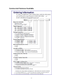
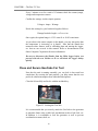
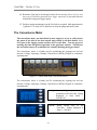
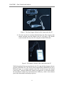
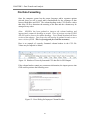
User’s Manual for GeoCubeTM
www.precisiongeothermal.com
Copyright Notice
GeoCubeTM User’s Guide
© 2015 Precision Geothermal, LLC. All Rights Reserved.
This guide is furnished for information purposes only and is furnished on an “AS
IS” basis without any warranties, whatsoever, express or implied. The information
in this manual is subject to change without notice, and should not be construed
as a commitment by Precision Geothermal, LLC.
Precision Geothermal, LLC assumes no responsibility or liability for errors or
inaccuracies that may occur in this book.
Except as permitted by such license, no part of this publication may be
reproduced, stored in a retrieval system, or transmitted in any means, electronic,
mechanical, recording, or otherwise, without the prior written consent of Precision
Geothermal, LLC.
Other brand and product names are trademarks or registered trademarks of the
respective holders. GeoCube is a trademark of Precision Geothermal, LLC
GeoCubeTM User’s Manual
Originally printed in December 2011
Printed in USA
Part No. GCENG-1000
Visit our Web site at http://www.precisiongeothermal.com
ii
Commercial Versions Available
iii
Statement of Warranty Policy
PRECISION GEOTHERMAL, LLC., (“PRECISION”), hereby provides to the original
purchaser (“Purchaser”) of the equipment set forth in the agreement between
PRECISION and Purchaser (the “Equipment”) the following warranty (the
“Warranty”). The Warranty is the sole and exclusive warranty provided by
PRECISION relating to the Equipment and any and all parts thereof and contains
the sole and exclusive obligation and liability of PRECISION relating in any way to
the Equipment and/or any part thereof. Except as provided in the Warranty,
PRECISION makes no other warranties, express or implied, and PRECISION
specifically disclaims all other express and implied warranties, including, without
limitation, the implied warranty of merchantability and the implied warranty of
fitness for particular purpose and any warranty relating to infringement or the like.
WARRANTY
Subject to the other terms and conditions contained in this Warranty, PRECISION
warrants to Purchaser that the Equipment and parts thereof will be free from defects in
material and workmanship (except minor defects in parts valued individually at $200.00
or less) for a period of one (1) year after the date of delivery of the Equipment to
Purchaser(the “Warranty Period”). To be valid, any Warranty claim must (1) be made
in writing to PRECISION at 5115 Industrial Street, Maple Plain, Minnesota 55359, (2)
set forth the Warranty claim in detail, (3) be received by PRECISION no later than the
end of the Warranty Period, and (4) include submission to PRECISION of completed
Warranty Activation Checklist prior to initial use of Equipment, and any Warranty claim
that fails to meet all the above requirements shall be null and void and of no force or
effect. No person or entity, other than Purchaser, shall have the benefit of the Warranty
and the Warranty may not be assigned to any other person or entity (whether by operation
of law or otherwise) without the written consent of PRECISION and any such assignment
shall be null and void and of no force or effect.
NOTICE AND PROCESSING OF WARRANTY CLAIM
PRECISION reserves the right to inspect the Equipment and parts thereof to determine
the validity of the Warranty claim and if determined to be valid solely by PRECISION,
PRECISION will, at its option, repair or replace the Equipment or parts thereof subject to
the valid Warranty claim. PRECISION’s obligation under this Warranty shall be
limited solely and exclusively to repair or replace the Equipment or parts thereof (at
PRECISION’s option) and PRECISION shall have no other liability or obligation of
any kind. PRECISION shall repair or replace the Equipment or parts thereof only at
PRECISION’s facility in Maple Plain, Minnesota or at any other location directed by
PRECISION. Purchaser shall pay all costs relating to the transportation of the Equipment
and any part thereof.
Any repair or replacement of the Equipment or parts thereof to any location other than
PRECISION’s facility in Maple Plain, Minnesota shall be subject to PRECISION’s then
iv
current charges for off-site Warranty claims which may include, without limitation, all
cost of travel and housing of individuals performing the repair or replacement. If
Purchaser requests repair or replacement work to be performed outside of the hours of
7:00 a.m. to 4:00 p.m., Maple Plain time, Monday through Friday (excluding
PRECISION holidays), then Purchaser shall pay PRECISION’s then current charges for
overtime Warranty work. Any repair or replacement of the Equipment or any part thereof
will continue to be warranted under this Warranty only for the remainder of the Warranty
Period.
WARRANTY EXCLUSIONS
Notwithstanding the foregoing, the following are not covered by and are excluded from
the Warranty and, as such, PRECISION provides no warranty, express or implied, with
respect to the following (the applicability of each shall be determined solely by
PRECISION):
1.
Components of the Equipment and/or any parts not manufactured by
PRECISION (“Third Party Parts”) which may include, but not be limited to, data
loggers, heating elements, various sensors, circulating pump, switches and other electrical
components. If any Third Party Parts are warranted to PRECISION by the person or
entity who manufactured such Third Party Parts and if PRECISION is permitted by the
terms of such warranty to assign such warranty to Purchaser then PRECISION shall
assign such warranty to Purchaser. Purchaser acknowledges and agrees that PRECISION
shall be under no obligation to negotiate with or obtain the permission of the
manufacturer of the Third Party Parts to the assignment of such warranty to Purchaser
and PRECISION’s sole obligation shall be to assign (if assignable by its terms) any such
warranty relating to such Third Party Parts to Purchaser. In the event Purchaser has the
benefit of any warranty on Third Party Parts, Purchaser agrees to make any and all
warranty claims with respect to the Third Party Parts directly with the manufacturer
thereof (and copy PRECISION) and PRECISION shall have no obligation to assist in
such claim or provide any such warranty.
2.
Components of the Equipment and/or any parts that are not part of
PRECISION’s standard design or are supplied pursuant to Purchaser’s special
requirements.
3.
Equipment and/or any part thereof which is subject to wear and tear or
consumed by the normal operation or use thereof including, but not limited to, heating
elements, circulating pump, and batteries.
4.
Any defect in any Equipment and/or any part thereof which arises from
the failure of Purchaser to properly maintain
and service the Equipment and/or any part thereof.
v
6.
Equipment and/or any part thereof which has been subject to improper use
and/or misuse, neglect, abuse, negligent repair or failure to provide reasonable and
necessary maintenance, or accident.
7.
Equipment and/or any part thereof which has been in contact with
corrosive chemicals or corrosive materials.
PRECISION GEOTHERMAL, LLC
5115 Industrial Street
Maple Plain, MN 55359
Phone: 952-255-7050
Fax: 763-479-2183
www.precisiongeothermal.com
vi
PREFACE - Table of Contents
Table of Contents
COPYRIGHT NOTICE .................................................................................. II
GeoCubeTM User’s Guide ...................................................................................... ii
Commercial Versions Available............................................................................ iii
Statement of Warranty Policy ............................................................................. iv
TABLE OF CONTENTS ................................................................................. 1
PREFACE.................................................................................................... 3
BEFORE YOU BEGIN ................................................................................... 3
Introduction: Typical Uses and Users ....................................................................3
Technical Overview ..............................................................................................4
Technical Specifications........................................................................................ 4
GeoCube Kit Contents ..........................................................................................4
Safety ..................................................................................................................5
WARNINGS ..........................................................................................................6
CHAPTER 1 ................................................................................................ 7
YOUR GEOCUBE ........................................................................................ 7
THE FIRST TC TEST ................................................................................... 10
Before the First Test ........................................................................................... 10
Initial System Check ............................................................................................ 10
Pump Check ........................................................................................................ 15
Heating Element Check ...................................................................................... 16
Equipment and Tool Checks ............................................................................... 19
Set-Up and Testing Procedure ............................................................................ 20
Establish Location ............................................................................................... 20
Fill the U Tube with Water ................................................................................. 20
Connect Loop Ends to Unit with Hose Clamps ................................................... 20
Insulate the Loops .............................................................................................. 21
Install the Ground Rod ....................................................................................... 21
Connect and Start the Generator ....................................................................... 22
Fill the Standing Column with Water ................................................................. 22
Purge the Air Out of the Pipes ............................................................................ 23
Set Up the Data Logger (Non-GSM Model) ........................................................ 23
Turn On the Pump .............................................................................................. 24
Select Heat Settings ............................................................................................ 24
Confirm Wattage Via Shuttle.............................................................................. 25
Close and Secure GeoCube For Test................................................................... 26
Take Down Procedure ........................................................................................ 27
1
PREFACE - Table of Contents
The Convenience Meter ..................................................................................... 28
CHAPTER 2 .............................................................................................. 30
DATA TRANSFER AND ANALYSIS ............................................................. 30
Overview ........................................................................................................... 30
Hoboware Pro Software ..................................................................................... 32
Hoboware Pro Software Installation .................................................................. 32
Ground Loop Design (GLD) Software ................................................................... 32
Hardware Requirements .................................................................................... 32
Software Requirements...................................................................................... 32
Operating System Requirements ....................................................................... 33
Internet Browser Requirements ......................................................................... 33
Installation Procedure ........................................................................................ 33
Initial Installation ................................................................................................ 33
Program Licensing .............................................................................................. 34
Software License Dongle .................................................................................... 34
How to Install the Dongle Driver: ....................................................................... 34
After Dongle Installation is Complete: ............................................................... 35
How To Transfer the Program Between Computers .......................................... 35
Dongle Activation for Apple Macintosh Computers .......................................... 35
Transferring Data from Data Logger Directly to HoboWare Pro Software ........... 35
Transferring Data from the Data Logger to the PC Via the Shuttle ...................... 41
Analyzing the Data in GLD .................................................................................. 42
International Considerations and File Formatting ............................................... 43
File Data Formatting ........................................................................................... 45
CHAPTER 3 .............................................................................................. 47
GEOCUBE MAINTENANCE ....................................................................... 47
Maintenance ...................................................................................................... 47
Notice: ................................................................................................................ 47
Cleaning The Unit ............................................................................................... 48
Corrosion Inhibition ........................................................................................... 48
Integrity Check ................................................................................................... 48
Cold Weather Storage ........................................................................................ 48
UPDATES ................................................................................................. 49
REVISIONS............................................................................................... 49
2
PREFACE - Before You Begin
PREFACE
Before You Begin
Note: All new GeoCube customers MUST review the warranty and perform the
bench testing procedure described in it before continuing. Failure to do so will
void the warranty.
This section describes the typical uses and users of the GeoCube. It also provides
a technical description of the GeoCube and what is included with the product. The
chapter concludes with a review of important safety considerations prior to using
the GeoCube.
Introduction: Typical Uses and Users
The GeoCubeTM is a durable, portable, safety-enhanced and user-friendly soil
thermal conductivity/response test unit for vertical and horizontal ground loop
heat exchangers. The unit includes a comprehensive data analysis software suite
that enables users to calculate conductivity, estimate diffusivity and share
professional, color reports with coworkers and clients. The GeoCube is designed
for use by professional geothermal HVAC designers, contractors and engineers
that need a quality in-house conductivity and testing capability.
The outer casing of the GeoCube, constructed of high grade aluminum, offers
significant protection from physical and cosmetic field-use wear and tear. The
exterior walls and internal dividers are encased in CF-25 insulation, minimizing
environmental thermal interference. Interior components provide for great usage
flexibility. The unit, capable of generating up to 13,000W of heating power, will
test borings up to 850 ft / 260 m deep. The soldered copper piping and HDPE
standing column continually purge air from the test loop. The Extended Capacity
GeoCubes feature a stainless steel manifold; accessible pressure relief valve and
externally serviceable heating elements.
3
PREFACE - Before You Begin
The unit is designed specifically to enable more geothermal professionals to
perform more conductivity tests in a wide variety of conditions and at a lower pertest cost. By providing these benefits, the GeoCube can assist in enhancing the
overall accuracy of a broad range of geothermal designs.
Technical Overview
This section lists the GeoCube technical specifications.
Technical Specifications
•
•
•
•
•
•
•
•
•
•
•
•
24 in x 24 in x 24 in / .61 m x .61 m x .61 m Exterior Dimensions
1 in / 25.4 cm Interior Silver Soldered Copper Piping
Extended Range models utilize stainless steel heat exchangers
HDPE Standing Column
1/6 HP Circulation Pump
50/60 Hz; 220/230/240 VAC
Locking Aluminum Case
CF-25 Insulation on Exterior Walls and Internal Dividers
13,000W Maximum Heating Power (varies per model)
Data Logger
Voltage, Amperage, Temperature and Flow Sensors
~150 lbs / 68 kg base shipping weight
GeoCube Kit Contents
The GeoCube comes with a variety of accessories. Please confirm your GeoCube
includes the following:
•
•
•
•
•
•
•
•
•
•
GeoCube test unit (400 ft/120 m, 500 ft/150 m, 725 ft/220 m, 850 ft/260 m
depth maximum)
Hobo Data Logger
Serial Cable for Data Logger
Hobo Shuttle for Interfacing with Logger
USB Cable for Shuttle
3.5mm Male-to-Male Cable for Logger-Shuttle Interface
HoboWare Pro Software CD and Manual for data collection
Hobo Limited Warranty
Software License Dongle/Key for Thermal Conductivity Analysis Module
of Ground Loop DesignTM program for data analysis and reporting
User Manual On CD (may be shipped separately)
4
PREFACE - Before You Begin
Optional Equipment:
•
•
•
•
•
•
Conductivity Test Tool Kit - includes the essential tools for performing
TC tests (hose hook-ups, filtered funnels, grounding lug tools, etc)
C-Kit (pipe adapter assembly)
H Valve (purging assembly)
GLD software - for full loopfield design.
Removable Extension Cords for Hassle Free Transport
Visit www.precisiongeothermal.com for other useful equipment.
Safety
IMPORTANT. READ THIS SAFETY INFORMATION PRIOR TO USING
THE GEOCUBE FOR THE FIRST TIME. ALSO, WATCH THE TRAINING
VIDEO PRIOR TO FIRST TIME USE. THE TRAINING VIDEO CONTAINS
IMPORTANT SAFETY INFORMATION.
Thermal conductivity tests have inherent risks associated with them. These risks
include but are not limited to the risks of electrocution and physical injury to
people and objects. This section describes important safety precautions that
GeoCube users should follow while using the GeoCube.
A thermal conductivity test utilizes high voltage/high amperage industrial power
generation and testing equipment and therefore requires maximum consideration
of safety before, during and after the test. Users should take similar precautions to
those taken when working with other high voltage equipment. At a minimum,
users must properly ground the GeoCube and the generator prior to use.
The GeoCube is constructed primarily of aluminum and rigid copper and weighs
approximately ~150 lbs / 68 kg. If improperly moved, stored or handled, the unit
has the potential to cause physical injury, death or damage. Users must use proper
handling, lifting, and storage techniques when working with the GeoCube to
reduce the risk of physical injury and/or damage.
The GeoCube includes a number of advanced safety features to reduce the
probability and severity of the aforementioned (as well as other potential) risks.
These safety features include:
•
•
Grounding: The GeoCube includes an external grounding cable
attachment lug for fast and easy grounding prior to use. Note that the unit
must be grounded prior to use to ensure safety.
Thermal Overload Protection: The GeoCube includes an
electromechanical switch that de-energizes the unit if the circulating
5
PREFACE - Before You Begin
•
•
•
•
•
•
•
solution temperature exceeds ~1300F/550C. This feature protects interior
electrical components.
Water Resistant Unit Controls: Water resistant controls reduce the risk of
water entering the electrical system, a situation that could lead to short
circuits and other hazardous electrical conditions.
Water Resistant Casing: Water resistant casing reduces the risk of water
entering the electrical system, a situation that could lead to short circuits
and other hazardous electrical conditions.
Electrical Overload Protection: All electrical circuits are fused for
overload protection.
Intrusion Detection: Upon accessing the core internal piping and plumbing
area of the GeoCube, the electricity de-energizes so that there is no live
electricity within the piping and plumbing area. Note that this area is offlimits to end users and accessing this area automatically voids any and all
warranties.
Durable, Tamper Resistant Case: A locking case protects the unit from
tampering. The case’s aluminum construction protects the overall unit
integrity. The single latch locking mechanism prevents unwarranted
access during testing.
Safety Labelling: Included warning and precaution labels remind users
and bystanders to maintain adequate safety measures when using or
interacting with the GeoCube.
Optional Detachable Extension Power Cord: An optional detachable
extension power cord reduces the risk of physical damage to users and
equipment.
WARNINGS
Unit is rated for a maximum voltage of 240V. Exceeding 240V could permanently
damage internal components.
Use two separate grounding lugs for the grounding rod- one for GeoCube and
one for generator.
THE GEOCUBE OPERATES UNDER HIGH VOLTAGE AND IMPROPER
USAGE CAN RESULT IN DAMAGE, INJURY OR DEATH. IN NO EVENT
WILL PRECISION GEOTHERMAL, LLC OR ITS SUPPLIERS BE LIABLE
FOR ANY LOST REVENUE, PROFIT, OR DATA, OR FOR SPECIAL,
INDIRECT, CONSEQUENTIAL, INCIDENTAL, OR PUNITIVE DAMAGES
HOWEVER CAUSED AND REGARDLESS OF THE THEORY OF
LIABILITY ARISING OUT OF THE USE OF OR INABILITY TO USE THE
GEOCUBE EVEN IF PRECISION GEOTHERMAL, LLC, OR ITS SUPPLIERS
HAVE BEEN ADVISED OF THE POSSIBILITY OF SUCH DAMAGES.
6
CHAPTER 1 - Your GeoCube
CHAPTER 1
Your GeoCube
Congratulations, the GeoCube™ is the industry-leading TC/TRT testing unit
designed to be used by contractors, drillers, engineers and professionals in the
Geothermal HVAC industry. The GeoCube features all of the tools that you will
need to correctly analyze and generate reports for the conductivity characteristics
of your geothermal project site.
While there are many configurations of GeoCube, they all feature some elements
in common. Below are some photos with descriptions of the features. These
photos cover some of the major models. Note: Your GeoCube may have slightly
different appearance depending on when it was made and which options were
ordered when the unit was produced. Your unit may have a mix of the features
shown in the photos:
Anti-Tamper Case Lock
Advanced Waterproof
Data Logger
Data Shuttle
Heater/Pump Control Panel
Fill Well
Electrical Connection
(May be pigtail connection)
Connections to Loop
Drain
7
CHAPTER 1 -
Circuit Breakers
Standard Logger
Control Panel
Fill Well
Advanced Data Logger on
Extended Range Model
Hi Temp Relief Valve
(Extended Range Models)
Fill Well on
Extended Range Model
Pigtail Power Cord
8
CHAPTER 1 -
Convenience Time/Electrical Meter
(NOT for data acquisition!!)
Exposed Access Panel
for Heaters on Extended
Range Model
9
CHAPTER 1 -
The First TC Test
This chapter describes how to perform your first thermal conductivity test with
the GeoCube. The chapter follows a step by step format. It starts with a “before
your first test” section, continues with the set-up and testing procedure and
concludes with the take down procedure.
Before the First Test
Prior to bringing the GeoCube out to the test site for the first conductivity test,
there are several preliminary steps that must be taken to ensure that the test runs
smoothly and to ensure that your warranty is active. Note that the results of this
initial system check need to be recorded on the Warranty Activation Checklist
(included in your sales contract) and submitted to Precision Geothermal, LLC
prior to the first test to ensure that the Warranty is not void. The below
instructions are identical to those in the warranty.
Initial System Check
Upon receipt of your Equipment it is essential that you perform several
preliminary steps to ensure that the Equipment is completely functional and was
not damaged in transit. Contact PRECISION immediately if you encounter any
problems during this procedure. Failure to follow this procedure prior to first use
will void the Warranty of your Equipment.
Software Installation and Logger Communications Check
Install the HoboWare Pro software on your PC if you have not done so already.
This software came on a CD with the GeoCube. Information about installation
can be found at www.onsetcomp.com. At the same time, download the Ground
10
CHAPTER 1 - The First TC Test
Loop Design (GLD) 2014 Premier Edition software from the following website
http://www.groundloopdesign.com/2014_commercial_download_request.html.
You will need to fill out the form on the webpage and then hit the "Submit"
button to initiate the download. After you have finished installing both the
HoboWare Pro software and the GLD software, please continue with the
following steps:
** For GSM model refer to Hobo U30 manual, page 11 for Hobo link setup.
1. Attach the Data Logger directly to the PC via a serial port cable. If your PC does
not have a serial port, use the included serial port-to-USB cable to facilitate the
transfer. If you need to use the included serial port-to-USB cable, you will need to
first install the drivers so that your computer can use the serial port-to-USB cable.
These drivers can be found on a CD that came with your serial port-to-USB
adaptor. If you are using the serial port-to-USB cable, it will look something like
this:
** For GSM model refer to Hobo U30 manual, page 13.
Figure 1: The Data Logger Attaches to the Computer Via a Serial Cable and a
Serial-to-USB Cable.
2. With the Data Logger attached to the PC, run the HoboWare Pro software.
3. Launch the Data Logger by pushing the Launch Device button as seen in Figure 2
below.
11
CHAPTER 1 - The First TC Test
Figure 2. Launching the Data Logger by Pushing the Launch Device Button
4. After a few seconds, the software will recognize the Data Logger as seen in
Figure 3 below. Select the Data Logger and hit ‘OK’.
If you do not see HOBO Energy Pro, please go to the 'File' dropdown menu at the
top of the program. A menu with several options will drop down. Please select
"Preferences" at the bottom of the list. A new window will open. In that window,
select 'Communications' and then find a "Serial Ports" button. Hit the 'Serial
Ports" button and then you will see a list of communications ports. Hit the "Select
All" option and then hit "OK". Close the Preferences window and try launching
the logger again as we did in step 3 above. If you do not see your Hobo Energy
Pro as it appears in Figure 2 below, you will need to close the HoboWare
Software and then re-launch it.
If you continue to have problems getting your Data Logger to connect to your
computer, please call Onset directly at 1-800-564-4377 and ask for tech support.
12
CHAPTER 1 - The First TC Test
Figure 3. Selecting the Data Logger
5. A Data Logger Launch window will open up as seen in Figure 4 below. Adjust
the logging interval to 20 seconds. In the launch options box (the big white box at
the bottom of Figure 4), confirm that the "Trigger: Push Logger Button" is
selected. Doing so confirms that data logging starts only after you push the start
button (explained later in the user manual). Push the “Launch” button at the
bottom of the window after doing so.
**For U30 model select (Now) in the launch options section.
13
CHAPTER 1 - The First TC Test
Figure 4. Adjusting the Logging Interval
6. After you hit the ‘Launch’ button, the Data Logger will be configured with the
new logging interval as seen in Figure 5.
Figure 5. Configuring the Data Logger with the New Logging Interval
14
CHAPTER 1 - The First TC Test
7. When the configuration is complete, it is safe to detach the data logger from the
PC. The data logger should now have a green blinking light next to the "Push to
Start" label on the logger. Confirm that the light is blinking and then proceed with
the pump check.
**U30 model will be logging at this time.
Pump Check
Pump Check
Check the circulation pump to make sure that it turns on and runs properly.
1. Attach the inlet and outlets together with a 1 inch / 25.4 cm diameter and
approximately 2 ft / 0.61 m long jumper hose. (Create short closed loop)
2. Remove the standing column plug and add approximately one to three gallons of
water (model dependent) into the GeoCube via the standing column. It is
recommended that you use a filtered funnel when adding the water to avoid
spilling fluids in the GeoCube control panel area. The open standing column can
be seen in Figure 6.
Extended Capacity GeoCube Example
Base GeoCube Example
Showing fluid filter in well and pressure relief valve
Figure 6. Remove the standing column plug, open pressure relief valve
(on applicable models) and then add water
3. To minimize the chance of splashing, place the plug loosely on top of standing
column.
4. Plug the GeoCube into a stable power supply with a minimum voltage of 208V.
15
CHAPTER 1 - The First TC Test
5. To purge air from system, run the pump for a few seconds by flipping the pump
switch. The pressure relief valve (some models) in the Extended Capacity
GeoCube may be momentarily opened to clear any air trapped in the heat
exchanger manifold.
6. Add more water to the standing column and repeat step 5 until water level is
maintained approximately 2 in to 3 in / 50 cm to 75 cm below cap.
7. Once all air has been purged, allow circulation pump to circulate throughout the
Heating Element Check below.
Heating Element Check
Next, check each heating element to confirm that each is working properly. To
perform this test quickly and accurately, the Data Logger default measurement
time interval (two minutes) needs to be changed to twenty seconds (we did this
already in Step 5 of the Software Installation and Logger Communications Check
section above). For this heating element check, the 20 second time interval is
critical because with the minimal water volume used in the test, the water
heats up very quickly and can result in automatic safety shutdown. Note that
under normal testing conditions, the interval should be set to 2 minutes. This
20 second interval is used only for the bench testing.
Please follow this procedure to check the heating elements:
1.
Put the Data Logger into the GeoCube and attach the sensor leads. See Figure 7A.
**Not applicable for U30 model.
Figures 7A. Attaching Sensor Leads to the Data Logger
2.
Attach the Shuttle to the Data Logger via the 3.5mm male-to-male cable. See
Figure 7B.
16
CHAPTER 1 - The First TC Test
**Use “mini USB” cord to connect shuttle to U30 model.
Figures 7B. Attaching the Shuttle to the Data Logger
3.
Turn the Data Logger on by pushing the ‘Push To Start’ button on the Data
Logger. You should now see a green, blinking light next to the "Logging" Label.
**U30 model should already be logging with green light blinking.
4.
Turn the Shuttle on by pushing the ‘On’ button. The Shuttle will prompt you to
continue via the built-in display. You will be able to cycle through to the current
and voltage sensors. This can be seen in Figure 8.
Figure 8. Shuttle Prompts
5.
Activate the Pump by switching the pump switch from the off position to the on
position as seen in Figure 9:
Figure 9. Turning on the pump (Control panel may vary)
17
CHAPTER 1 - The First TC Test
6.
Turn on the lowest wattage heating element (the switch immediately to the right
of the pump switch) and monitor the current. Look for a greater than 5 amp draw.
The exact amperage will depend on the voltage of the power supply but it should
be greater than 5 amps. All elements are rated at 240 volts; any voltage setting
less than 240V will yield less wattage from each element. Since the Data Logger
is set to record data every 20 seconds, data will be output to the Shuttle every 20
seconds. To see the updated sensor data, you will need to re-scroll through the
sensors on the Shuttle. This is because the Shuttle screen does not automatically
refresh itself. The user needs to refresh it by scrolling through the sensors again.
7.
Turn off the first heating element and then turn on the second heating element.
Monitor the current and voltage for 20 seconds (until you see the current and
voltage on the Shuttle screen) and confirm the amperage is greater than 5 amps.
8.
Turn off the second heating element and then turn on the third heating element
and repeat.
9.
Turn off the third heating element and then turn on the fourth heating element and
repeat.
10. On the shuttle, there is a section called "Counts". “Counts” refers to 1 gallon per
logging interval. For example, since our logging interval is 20 seconds, you
multiply the counts by three (3) to calculate the flow rate in gpm. Note that during
a TC test, the logging interval is two (2) minutes so that during a test, you divide
the counts by two (2) to calculate gpm. Note: The software will work with
English or Metric units.
11. If the unit shuts off during this test it is because the water reached too high of a
temperature and the built-in safety mechanisms kicked in. In such a case, turn off
and unplug the GeoCube, drain the water out of the GeoCube via the drain plug
(which is located on the same side of the unit as the inlet and outlets), and then
repeat the steps in the Pump Check section.
12. When the test is complete, confirm that all four heating elements are turned off,
turn off the pump and drain the GeoCube.
13. The final step is to reset the Data Logger so that it records data at 2 minute
intervals.
Follow
the
procedure
outlined
above
to
do
so.
Failure to set the Data Logger back to the 2 minute interval
will result in post-test data analysis failure.
14. Remember to submit your Warranty Activation Checklist to PRECISION
GEOTHERMAL.
18
CHAPTER 1 - The First TC Test
Equipment and Tool Checks
Be sure to bring all of the appropriate tools and equipment that you need for your
test. We recommend the Precision Geothermal TC Toolkit which is available at
www.precisiongeothermal.com. Included with this kit is comprehensive
documentation on conductivity tests developed from many years of experience.
Undisturbed Soil Temperature - Analysis Methods
Before performing a conductivity test that thermally alters the near field
ground temperature, it is a good idea to determine the undisturbed ground
temperature. While there are many methods for doing so, two popular and
straight-forward methods are as follows:
1) Drop a temperature sensor into the loop pipe and take readings at 50
foot increments until maximum depth. The average temperature
reading is a good approximation of the undisturbed soil temperature.
For this method to be accurate, the fluid filled pipe should sit
undisturbed for at least 5 days or in accordance with ASHRAE
guidelines.
2) After setting up the GeoCube (see below), insert a probe into the
standing column. Be sure to measure the temperature immediately
after you start running the pump and BEFORE you turn on the
heating elements. After the temperature stabilizes (usually this takes
only a few minutes), record the temperature. Typically after 10-15
minutes the heat from the circulation pump will begin heating up the
water be sure to complete your undisturbed temperature analysis
quickly. Note that this second technique may not be as accurate as
the first technique. By adding water into the standing column, the
undisturbed ground temperature may be over or under estimated
(depending on the volume and temperature of the water added to the
standing column).
Figure 10. Inserting the Temperature Probe into the Standing Column
19
CHAPTER 1 - The First TC Test
Set-Up and Testing Procedure
Establish Location
Place the GeoCube on stable, level ground. Be sure the GeoCube is close
enough to the loop ends so that it is easy to attach the loop ends to the
GeoCube.
Figure 11. Place the GeoCube on Stable Ground
Fill the U Tube with Water
If the U tube is not already filled with water, fill it. Please note that if you
are filling the tube immediately before the test you will not be able to
measure the undisturbed ground temperature via water temperature
measurements since it may take several days for the water temperature to
stabilize.
Connect Loop Ends to Unit with Hose Clamps
To facilitate purging, hook up inlet pipe first and fill GeoCube via the
standing column until water comes out the outlet port of the GeoCube.
Once water is coming out of the outlet port, hook up outlet pipe to outlet
port.
Figure 12. Attach the Loops to the Inlet/Outlets and Secure Them
(Your Unit May Look Different)
20
CHAPTER 1 - The First TC Test
Insulate the Loops
It is essential to properly insulate the loops to minimize heat loss and
maximum data accuracy. It is recommended that users insulate the
exposed loop pipes with plumbing pipe wrap and duct tape. In extremely
cold weather other measures may be necessary.
Figure 13. Insulate the Loops
Install the Ground Rod
The grounding rod is a critical safety feature. Users should co-locate the
GeoCube and the generator grounds on the same grounding rod. General
grounding rod recommendations suggest that the grounding rod should be
driven at least 3 to 4 feet / 1 to 1.5 meters below grade.
After the grounding rod is in place, connect the GeoCube to the grounding
rod. To do so, first connect the grounding wire to the ground lug which
can be found on the outside back of the GeoCube case. Connect the other
end of the grounding wire to one of the grounding rod lugs on the
grounding rod.
Connect the generator to the grounding rod in a similar fashion, being sure
to use a second grounding lug on the grounding rod. You will need two
grounding lugs on the grounding rod: one for the GeoCube and one for
the generator.
Figure 14. Grounding the GeoCube and the Generator
21
CHAPTER 1 - The First TC Test
Connect and Start the Generator
Connect the GeoCube to the generator and then start the generator. The
generator should be set for 240 Volts. Although in some cases users may
use a lower voltage, the maximum voltage is 240 Volts. Never exceed 240
Volts. Never drop below 200 Volts.
Figure 15. 240V Maximum Setting
Fill the Standing Column with Water
Now that the all of the attachments are in place, the standing column
should be filled with water in anticipation of purging the air out of the
system.
Remove the J plug from the standing column and add approximately one
gallon of water into the column. Use a filtered funnel like the one
available in the TC Toolkit to ensure that a) there is no spillage into the
control panel area of the GeoCube and b) no debris gets into the standing
column. Add enough water so that there is a 2 in to 3 in / 50 cm to 75 cm
air gap at the top of the column.
Figure 16. Fill the Standing Column for a 2-3 in/ 50-75 cm Air Gap at the Top
22
CHAPTER 1 - The First TC Test
Purge the Air Out of the Pipes
With the standing column cover off, intermittently turn the pump on and
off by toggling the circulation pump switch on and off.
Figure 17. Toggle the Pump
Turning the pump on and off protects the pump from cavitating (the
formation of unwanted air bubbles) and drylock. Toggle the pump on and
of to evacuate any air trapped in the loop. Depending on the volume of air
in the loop, it may take 20 minutes or longer to fully purge the system.
Add water as necessary into the standing column to obtain a level 2-3 inch
/ 50-75 cm below the top of column. Use the pressure relief valve (on
Extended Capacity models only) to purge the internal manifold.
When the purging process is complete, attach the standing column cap/J
plug and tighten it. To ensure a tight fit, consider using pliers or other
tools as necessary.
Set Up the Data Logger (Non-GSM Model)
Plug all sensor connections into the data logger and place the data logger
in its cradle.
Next, turn the data logger on by pushing the ‘On’ button. Look for a faint
flashing LED light next to the word “Logging” that indicates that the unit
is turned on.
Figure 18. Turning the Data Logger on while it is Sitting in its Cradle
23
CHAPTER 1 - The First TC Test
Turn On the Pump
Now the data logger is plugged in and turned on. Turn on the pump by
flipping the switch on.
Figure 19. Turn on the Circulation Pump
Select Heat Settings
Typical test specifications call for 15 watts minimum / 25 watts maximum
per vertical foot or 49-82 watts per vertical meter of bore hole. The four
heating elements in the GeoCube provide for great testing flexibility.
Compute the necessary power before starting your test! As seen in the
table below, at 240V the first element provides 1500W and the other three
elements each provide 2000W. At 208V, each element de-rates by
approximately 500W. Note that you should NEVER exceed 240V.
400/500 ft & 120/150 m Units
Element
Element 1:
Element 2:
Element 3:
Element 4:
Element 5:
240 Volts
1500W
2000W
2000W
2000W
208 Volts
~1000W
~1500W
~1500W
~1500W
725 ft / 220 m Unit
240 Volts
2500W
2500W
3000W
3000W
208 Volts
~2000W
~2000W
~2500W
~2500W
850 ft/260 m Unit
240 Volts
2000W
2500W
2500W
3000W
3000W
208 Volts
~1500W
~2000W
~2000W
~2500W
~2500W
Below is an example of how to select which elements to use for a 200 ft /
61 m borehole:
The optimal power range for a 200 ft / 61 m borehole is the following:
Min: 200 ft x 15 watts/ft ~ 3,000W or Min: 61 m x 49 watts/m ~ 3,000W
Max: 200 ft x 25 watts/ft ~ 5,000W or Min: 61 m x 82 watts/m ~ 5,000W
It is reasonable to select an intermediate value of 4,000W to achieve a flux
of ~ 20 w/ft or ~ 65.5 w/m. At 240V, users can select Element 2
(2,000W) and Element 3 (2,000W) for a combined 4,000W. Users can
also select Element 3 (2,000W) and Element 4 (2,000W) or any other
combination of elements that add up to the desired 4,000W.
24
CHAPTER 1 - The First TC Test
Users could also combine Element 1 (1,500W) and Element 2 (2,000W)
for a combined 3,500W (17.5w/ft or 57.4w/m.) This is within the range of
15-25 watts/ft or 49-82 watts/m, which are the desired power range.
Confirm Wattage Via Shuttle
Confirm the wattage (and heating element activation) prior to conducting
the full test. With the included Shuttle (a device for reviewing the data
logger performance as well as transferring test data to a PC), confirmation
is straightforward and quick. This step will also confirm that all readings
are being correctly received by the Data Logger. Failure to confirm
correct readings may cause invalid test data recordings and require
retesting!
Plug the Shuttle into the Data Logger using the included 3.5mm male-tomale cable.
Figure 20. Attaching the Shuttle to the Data Logger
Turn the Shuttle on by pushing the ‘On’ button. The Shuttle will prompt
you to continue via its built-in display. You should be able to cycle
through and read all the sensors. If you can’t read the sensors, you are
NOT capturing the data needed for a successful test!
Figure 21. Monitoring the Sensor Readings
25
CHAPTER 1 - The First TC Test
Every 5 minutes or so for a total of 15 minutes check the current (amps),
voltage and temperature sensors.
Confirm the wattage via this simple equation:
Voltage x Amps = Wattage
Divide this wattage by your borehole length as follows:
Wattage/borehole length = w/ft. or w/m.
Once again, the optimal range is 15-25 watts/ft. or 49-82 watts/meter.
As you observe the sensor outputs via the shuttle, you may also notice that
the temperature is increasing, as it should. Note that the Shuttle has
numerous other features such as offloading data and starting the logger,
etc. that are not covered in this manual. Refer to documentation from
Onset Computer Corporation for more information.
Be sure to disconnect the Shuttle from the Hobo logger before you
proceed with the test. Failure to do so will drain the logger battery
quickly.
Close and Secure GeoCube For Test
Now that the unit is running smoothly, you can lock it down until test
completion. By securing the unit properly, you help ensure that the test
proceeds without interruption from interested third parties.
Close the lid carefully and lock it with the included key.
Figure 22. Locking the GeoCube
It is recommended that you securely attach the GeoCube to the generator
or generator frame using a cable lock mechanism such as a bike lock, etc.
In addition, it is reasonable to lock the generator as well to prevent
accidental movement, theft, etc.
26
CHAPTER 1 - The First TC Test
Take Down Procedure
When the test is complete, follow this sequence of steps to safely end the test:
1)
Unlock and open the GeoCube.
2)
Via Shuttle, check all sensors to confirm that volts, amps and counts (flow)
are the same as they were when you started the test. Check temperature
sensors to confirm that they are providing expected results.
3)
Shut down all of the active heating elements.
4)
Shut down the pump.
5)
Attach the shuttle to the Data Logger to stop the data logger (optional). After
doing so it is a straightforward process to transfer the data from the logger and
on to the shuttle and then to transfer it again onto a PC via the shuttle’s USB
port. See the data logger instructions for more details.
6)
Be sure to shut off the Data Logger as per the Data Logger instructions to
preserve the battery life. Note that the easiest way to shut off the Data Logger
is by attaching it to your computer, running the Hoboware software and
turning off the unit. While this procedure may seem cumbersome, the purpose
is to protect the user from running a test with a deactivated Logger.
7)
Disconnect the data logger (and data shuttle) and store them in a safe place.
8)
Shut off the generator.
9)
Disconnect the GeoCube power cord from the generator.
10) Disconnect the grounding rod from the generator and the GeoCube.
11) Disconnect the ground loop from the GeoCube.
12) Wipe out any condensation inside the GeoCube.
13) Recap the loops.
14) Drain the GeoCube by opening the drainage plug which is located below the
inlet and outlets.
15) After the unit is drained, replace the drain plug.
27
CHAPTER 1 - The First TC Test
16) Return the GeoCube to its storage location for its next use. Store in a dry area,
leave top of GeoCube open and store logger separately if your unit does not
include the waterproof logger option.
17) Perform routine maintenance on the GeoCube as required. Add approximately
1 gallon or 3.78 liters of RV antifreeze to keep the pump and motor clean.
The Convenience Meter
The convenience meter was introduced by user request as a way to easily look at
the status of test after it has been started and verified by the data shuttle. It is
NOT part of the logging system and does NOT record data. You can use it for
tracking the time and general operation of the generator and test. NEVER use
the convenience meter as a substitute for actually checking the logger status!!
The convenience meter is a handy tool for monitoring the ongoing test and can
measure Voltage, Amperage, Wattage, Timed Power (KWh), Elapsed or cumulative
operating time.
Figure 23. Control Panel with Convenience Meter
The convenience meter is a handy tool for monitoring the ongoing test and can
measure Voltage, Amperage, Wattage, Timed Power (KWh), Elapsed or cumulative
operating time.
Voltage: Reads voltage input from the
generator to the GeoCube. Range
displayed is from 80.00 ~
264.00VAC
Current:
28
Reads current flow to the
GeoCube. Range displayed is
from 0 ~ 100.00A.
CHAPTER 1 - The First TC Test
Timed Power: Displays cumulative power
from 0 to 9,999.99 kWh.
Power:
Displays the present power load
from 0 ~22,000 W.
Time:
Displays running or cumulative
time from last reset.
Range
displayed is 0 ~9,999:59 hours
Buttons: Used to switch between modes and
to reset the accumulated data
Up Button:
In normal operation, Time, Current, Total Power, Power, Voltage,
will be displayed by short presses to move between readings.
Down Button:
Similar to the Up Button, but will move in reverse order. Up and
Down Buttons will rotate fully between all items and repeat the
sequence.
Set Button:
During the cumulative power or time display, pressing the set
button for (3) seconds will reset the convenience meter to zero.
OK Button:
In regular operation, a short press will turn the backlight on or off.
Remember, this convenience meter is in NO WAY connected to the logging function and
is to be used for convenience only. If the meter is never reset, it will record the total
operating time of the GeoCube under power. While the meter is protected inside the
closed lid, it should be protected from unnecessary moisture, rain, and etc. The meter
will function with input frequencies of 45~65 Hz so should be suitable for all generators.
29
CHAPTER 2 - Data Transfer and Analysis
CHAPTER 2
Data Transfer and Analysis
This chapter begins with a general overview of how to analyze the GeoCube test
data. It then goes into detail, beginning with directions for how to install the two
required and included software programs (HoboWare Pro and Ground Loop
Design). The chapter continues by describing how to move the collected data
from the data logger either directly to the PC or via the shuttle to the PC. In either
case, the HoboWare Pro software will manage the transfer. Finally, the chapter
covers how to transfer the data into the Ground Loop DesignTM software thermal
conductivity module for the thermal conductivity analysis and diffusivity
estimation.
Overview
At the end of a conductivity test, the data from the GeoCube’s sensors are stored
on the Data Logger. These data need to be transferred to a PC for data analysis.
The data transfer can be accomplished via two methods:
1) The data can be transferred directly from the Data Logger to the PC
via a serial port or via a serial port and a serial-to-USB adaptor cable.
In Figure 1, the Data Logger is connected to a serial cable which in
turn is connected to a USB adaptor.
30
CHAPTER 2 - Data Transfer and Analysis
Figure 1. The Data Logger is Ready to Be Connected to the PC
2) The data can also be transferred/shuttled from the Data Logger to the
Shuttle and then from the Shuttle to the PC. In Figure 2, the Shuttle
can be attached directly to the PC using the included USB cable.
Figure 2. The Shuttle is Ready to Be Connected to the PC
With both methods, Data are transferred to the PC using the Data Logger software
program, HoboWare Pro. The data are then exported from HoboWare Pro into a
Microsoft Excel .csv (comma separated value) file. In the last step, the Ground
Loop DesignTM thermal conductivity module can import the .csv file and calculate
the soil thermal conductivity and estimate the diffusivity, which is the ultimate
goal of this data transfer and analysis process.
31
CHAPTER 2 - Data Transfer and Analysis
Below is a visual overview of the data transfer process options:
Hoboware Pro Software
Hoboware Pro Software Installation
The HoboWare Pro software CD and an instruction manual are included in
the GeoCube package. Install the HoboWare Pro software following the
included instructions. If you have any difficulties with the installation
process, please contact Precision Geothermal, LLC.
Ground Loop Design (GLD) Software
Hardware Requirements
A full installation has the following minimum hardware requirements:
•
•
•
1 GB RAM (2 GB recommended)
150 MB hard disk space (300 MB recommended)
Intel Pentium M Processor or newer
Software Requirements
GLD has the following software requirements:
•
System running under Windows® XP, Vista, W7, W8.x or W10
32
CHAPTER 2 - Data Transfer and Analysis
•
Google Chrome, Mozilla Firefox or Internet Explorer®
Operating System Requirements
GLD will operate under Windows XP/VISTA/W7/W8/W10. GLD will
operate under Apple Macintosh Parallels as well.
Internet Browser Requirements
An Internet browser is required only for viewing the data reference files,
and not for general program operation. To access the data reference files,
at least one of the following browsers is necessary:
•
•
Internet Explorer Version 8 or later.
Chrome Browser Version 10 or later
Most any modern browser will work. When reference file pages are
opened, the default browser in the user PC will be used to view the pages.
Installation Procedure
If you have problems installing GLD, please visit the support page at
www.groundloopdesign.com or contact your distributor. Note that you can
also download GLD from the internet at the following web address:
http://www.groundloopdesign.com/2014_commercial_download_request.
html. The downloadable version always will be the most recent release.
Initial Installation
For CD versions of GLD, installation should start automatically. If not,
the software may be installed by clicking on the Setup.exe file included
on the disk.
The program is set to install in the folder:
(Main Drive):\Program Files\Gaia Geothermal\GLD2014
If desired, the user can specify a different location during the installation
process.
The example above is for a 32 bit Windows OS installation such as
Windows 7 or Windows 8. In a 64 bit windows installation, “Program
Files” will be replaced with “Program Files (x86)”
33
CHAPTER 2 - Data Transfer and Analysis
Program Licensing
This section describes the USB dongle and license transfer options
available in GLD.
Software License Dongle
Your GLD Thermal Conductivity module software license is stored on the
USB dongle that came with your GeoCube. This dongle enables you
effortlessly to transfer GLD from one computer to another. Please be
careful not to misplace this dongle. Lost dongles cannot be replaced
without the purchase of a new license.
If the dongle is not attached to your computer, GLD will function as a trial
version, which is fully functional except for a few design parameters that
are locked at certain values.
When you insert the dongle into a free USB port on your computer for the
first time, your computer most likely will recognize the dongle and after a
few seconds, the dongle light will turn on. When it turns on, your license
will activate. However, if your computer indicates that the dongle is “new
hardware” you have two options for installing the dongle driver:
How to Install the Dongle Driver:
Windows users with internet access:
If your computer has access to the internet, your computer can
automatically install the drivers. Follow along with the Windows new
hardware wizard to install the drivers. The process takes a few minutes.
When the installation is complete, the dongle light will turn on.
All other users:
Via Windows Explorer, navigate to:
(Main Drive):\Program Files\Gaia Geothermal\GLD2014\Extras
The example above is for a 32 bit Windows OS installation such as
Windows 7 or Windows 8. In a 64 bit windows installation, “Program
Files” will be replaced with “Program Files (x86)”
In the Extras folder you will find a HASPUserSetup.exe program.
34
CHAPTER 2 - Data Transfer and Analysis
Run the program to install the dongle driver. When the installation is
complete, the dongle light will turn on.
After Dongle Installation is Complete:
Now that the dongle is installed, you can access the full functionality of
the GLD version that you purchased. If you remove the dongle, the
program will revert to demo mode. If you reattach the dongle, the program
will reactivate again.
How To Transfer the Program Between Computers
The dongle licensing system allows the user to transfer the license from
one computer to another. If a user decides to transfer GLD from one
computer to another, all he or she has to do is the following:
•
Install GLD onto the target computer.
•
After the “demo version” of the program is running on the new
computer, attach the dongle and follow the above instructions
regarding dongle driver installation.
Dongle Activation for Apple Macintosh Computers
Use this command in the Darwin (Unix) window of the Terminal Utility in
the Utilities folder (there is no need to restart the computer or Parallels):
sudo launchctl unload/Library/LaunchDaemons/com.aladdin.aksusbd.plist
Transferring Data from Data Logger Directly to
HoboWare Pro Software
For personal computers that have serial ports or USB ports, data can be
transferred directly from the data logger to HoboWare Pro via the following
process:
1) Attach the data logger directly to the PC via a serial cable (included or
via a serial cable and serial-to-USB adaptor (included). See Figure 3.
35
CHAPTER 2 - Data Transfer and Analysis
Figure 3. The Data Logger to Serial Cable to Serial-to-USB Adaptor
Enables the User to Connect the Data Logger to the Computer
2) Run the HoboWare Pro software.
3) Choose 'Readout' from the Device dropdown menu as seen in Figure 4,
below.
Figure 4. Choose 'Readout', the second option from the top.
36
CHAPTER 2 - Data Transfer and Analysis
4) In the window that opens up, select the Data Logger and push ‘Ok’. See
Figure 5 below. It may take a few seconds for the software to recognize
the unit.
Figure 5. Select the Data Logger
5) After the file is transferred automatically to the computer, you will be
asked to save the file. Note: you should save the file as your project name
so you can find it later if necessary. Then hit 'Save'.
37
CHAPTER 2 - Data Transfer and Analysis
6) A Plot Setup screen will open. Push the ‘Plot’ button as seen in Figure 6.
Figure 6. Plotting the Data
VERY IMPORTANT: GLD requires that all of the items above are present in the data
file. If any are missing, the data analysis by GLD will fail or give an error message with
invalid results!
38
CHAPTER 2 - Data Transfer and Analysis
7) A screen similar to the one in Figure 7 can now be seen. Push the
‘Export Table Data’ button.
Figure 7. Prepare to Export the Table Data
8) Choose ‘export to a single file’ and click ‘OK’ as seen in Figure 8.
Figure 8. Select an Export Option
39
CHAPTER 2 - Data Transfer and Analysis
9) In this last step, name the file to be exported and choose an export
location. Choose the following folder:
MAIN DRIVE/Program Files (x86)/Gaia Geothermal/GLD2014/Thermal
Conductivity/Thermal Conductivity Data Files
Click the ‘Save’ button.
By exporting/saving the file to the above folder, GLD can easily find and
import the data into the Thermal Conductivity analysis module as
illustrated in Figure 9.
If the file is not saved to this folder, the analysis software may not function
properly.
Figure 9. Saving the csv File in the Thermal Conductivity Data Files folder
If you find that you cannot write to this folder due to permissions issues of
your PC and operating system, you will need to set the correct permissions.
In the Windows file explorer, navigate to this folder:
MAIN DRIVE/Program Files (x86)/Gaia Geothermal
40
CHAPTER 2 - Data Transfer and Analysis
Right Click on the folder and choose “Take Ownership of Files / Folders”
Figure 9.5. Taking Ownership of the Gaia Geothermal folder
Once you have taken ownership of the folder, you should be able to write
your data file properly.
Transferring Data from the
Data Logger to the PC Via the Shuttle
While we recommend that the user transfers data directly from the logger to the
computer following the procedure described above, in some cases this may not be
feasible. In such instances, it is possible to transfer test data from the logger to the
shuttle and then from the shuttle to the PC. The procedure for transferring data via
the shuttle intermediary is similar to the procedure for transferring data directly
from the Data Logger and to the PC (as described above). See Figures 10 and 11
for a brief overview. For more details, please refer to the to the logger and shuttle
manuals.
41
CHAPTER 2 - Data Transfer and Analysis
Figure 10. Attach the Shuttle to the Data Logger With the 3.5 mm Male-to-Male
Cable to Transfer Data to the Shuttle.
Figure 11. Attach the USB Cable to the Shuttle to Transfer Data to the Computer.
Analyzing the Data in GLD
Now that the raw data has been downloaded onto the PC and exported/saved as
a .csv file, the GLD software can analyze the data and calculate the thermal
conductivity value. To perform this analysis, please see GLD Thermal
Conductivity Software Module User’s Manual. This manual provides an overview
of the GLD software as well as a description of how to use GLD for analyzing
conductivity test data. In GLD version 2014 and later, the software will
automatically detect redundant sensors and select the pair based on stability of the
data. It usually does not matter which pair is used since the results are ideally the
same between the pairs. (Note: GeoCube owners may always update their
license to the latest version of GLD at no additional charge!)
42
CHAPTER 2 - Data Transfer and Analysis
International Considerations and File Formatting
Every effort has been made to provide tools that allow tests and analysis to be
performed anywhere in the world. There are some steps that need to be
considered if you are working in a computer environment where the operating
system default language is set to a language other than English. The language
itself is not an issue but the standard units and punctuation can vary depending on
the region of the world. While dates, units, currency and other items may seem
interchangeable in everyday use, the computer systems and software are not
always aware of the differences and we must provide exact formats for data to be
transferred between software programs.
A standard engineering practice for exchange of data files involves the use of files
that are referred to as .CSV, which stands for “Comma Separated Values”. Many
software tools and programs use the CSV file as the standard for interchange,
including GLD and Hoboware, which are provided with your GeoCube. The data
export from Hoboware to GLD is in the form of a CSV file and the process to
transfer data is generally very straight-forward. There have been issues with
computer systems that are set up for some regions of the world where the
formatting that is controlled by the operating system (Windows, Linux, etc)
substitutes a different symbol other than a comma for list separation. When a user
is working on a system that has different default units, the data transfer to a CSV
file will contain data separators that are not recognized by GLD and an error will
occur that may look like the following:
Figure 12: File Formatting Error Dialog Box
There are a couple ways to eliminate the “file format” issue.
Method 1:
Set the default language of the computer OS to “US English”.
This has obvious drawbacks if the user is not native English
speaking but resolves the issue of file formatting.
Method 2:
Change the default list separator value of the computer operating
system to use commas as the default. This is generally an easier
long term correction.
In the figures below, screenshots of a typical Windows system illustrate how to
make these changes:
43
CHAPTER 2 - Data Transfer and Analysis
Open the Control Panel (your appearance may vary based on the computer OS)
Choose the Region and Language Settings. The following dialog boxes appear:
Select Additional Settings:
Figure 13: Region and Language Settings in the Control Panel
In the first box, you can select a language. This can be used for Method 1. If you
want to retain a different native language, then you can set the “list separator”
option in the additional options dialog box to be a comma, as suggested for
Method 2.
Once a file is created, the formatting is defined in the file headers and cannot be
changed. The file must be re-exported with the correct settings in the OS to
change the list separator values.
44
CHAPTER 2 - Data Transfer and Analysis
File Data Formatting
Once the computer system has the proper language and/or separator options
selected, there are still a couple other considerations for the exchange of data
between HoboWare and GLD. The column headings in the CSV file have values
that allow GLD to determine the meaning of the data and the columns may be
arranged in any order.
(Note: GLD2014 has been updated to interpret the column headings and
appropriately rename the headings as needed. Users of previous versions of GLD
will still need to observe the column headings. Users should download the latest
version of the software. Your license key will need to be updated in order to use a
newer version of GLD. This is a free upgrade for GeoCube customers)
Here is an example of correctly formatted column headers in the CSV file.
Values may be Imperial or Metric:
Figure 14: Headers of Correctly formatted CSV data file for GLD Import
If the column headers contain any extraneous information, the import process into
GLD could experience the following error:
Figure 15: Error Dialog for Improper Column Headers
45
CHAPTER 2 - Data Transfer and Analysis
This can occur if the user has customized the labels inside of Hoboware when the
shuttle data is read and the CSV file is exported. Here is an example of incorrect
column headers that cause the error shown in Figure 15:
Figure 16: Example of Improper Column Headers
In the above Figure 16, the label for column E has been expanded to illustrate a
label that contains extraneous information the user has introduced through
Hoboware. When the data is retrieved from the data shuttle, the plot dialog box
should not contain any extra data labels.
Figure 17: Example of Correct Plot Setup in Hoboware
Note in the above example that the Label column does not contain any additional
data. This is the correct way to set up the Hoboware software for plotting the data
and exporting the CSV file. This column MUST be left blank or an error will
occur when importing the file to GLD.
46
CHAPTER 3 - GeoCube Maintenance
CHAPTER 3
GeoCube Maintenance
This brief chapter describes the routine maintenance that will keep the GeoCube
functioning smoothly.
Maintenance
Maintaining the GeoCube is a fairly straightforward process. Maintenance
consists of three primary activities: cleaning the unit, corrosion inhibition and
confirming unit integrity.
Notice:
Under no circumstances should the user open up any of the interior panels.
Doing so will void any warranties. If anything beyond routine maintenance is
necessary, contact the manufacturer.
The Extended Range GeoCube is the only model with externally replaceable
heating elements. These may be field replaced. Please contact PRECISION
GEOTHERMAL for instructions and replacement elements.
CHAPTER 3 - GeoCube Maintenance
Cleaning The Unit
Cleaning the GeoCube’s exterior after use enhances unit longevity. Add
approximately 1 gallon / 3.78 liters of RV antifreeze to keep the pump and motor
clean.
Corrosion Inhibition
After every 5th test, circulate CST-50 fluid through the unit for one hour after
connecting the supply and return together via a 1” hose. After circulating CST-50
for one hour, drain the unit.
CST-50 is a special liquid of corrosion inhibitors and chelators designed for the
protection of closed heating and cooling water systems. CST-50 will protect both
ferrous and non-ferrous metals and should be used in water systems where there is
little or no make-up water. CST-50 does not contain chromates or other toxic
pollutants.
CST-50 is available from www.chemicalspec.com.
Integrity Check
Periodically check to confirm that screws are tight.
Cold Weather Storage
Be sure to fully drain the unit when it will be stored in freezing temperatures.
Failure to fully drain may result in damage if the fluid freezes and expands.
48
UPDATES - Revisions
UPDATES
Revisions
November 2015
• Added details for Convenience Meter
• Added “Your GeoCube” photos and section to Chapter 1
August 2015
• Added Metric references
• Added CE marking on labels
• Updated information for Windows 10
July 2014:
•
•
Misc Clarifications for fixing security on file folders
Additional warnings regarding checks before running field TC test
March 2014:
•
•
Added additional references to Extended Capacity GeoCube models
Updated references to software changes and revisions
February 2013:
•
Added section on International use and file formatting considerations