1
B8
ENGINE CONTROL SYSTEM
3SZ --------------------------------------- B81
ENGINE CONTROL COMPUTER ------- B81
REMOVAL AND INSTALLATION------- B81
ENGINE REVOLUTION SENSOR ------- B82
REMOVAL AND INSTALLATION------- B82
CAMSHAFT POSITION SENSOR ------- B83
REMOVAL AND INSTALLATION------- B83
KNOCK SENSOR ---------------------- B84
REMOVAL AND INSTALLATION------- B84
ENGINE WATER TEMPERATURE SENSOR ----------------------------------- B85
REMOVAL AND INSTALLATION------- B85
INTAKE AIR TEMPERATURE SENSOR
--------------------------------------- B86
REMOVAL AND INSTALLATION------- B86
MANIFOLD ABSOLUTE PRESSURE
SENSOR------------------------------- B87
REMOVAL AND INSTALLATION------- B87
OIL CONTROL VALVE------------------ B88
REMOVAL AND INSTALLATION------- B88
THROTTLE POSITION SENSOR-------- B89
REMOVAL AND INSTALLATION------- B89
IDLE SPEED CONTROL VALVE ------ B811
REMOVAL AND INSTALLATION----- B811
FRONT OXYGEN SENSOR----------- B812
REMOVAL AND INSTALLATION----- B812
REAR OXYGEN SENSOR(REAR OXYGEN SENSOR EQUIPPED VEHICLES
ONLY) ------------------------------- B814
REMOVAL AND INSTALLATION----- B814
ENGINE CONTROL SYSTEM--------- B816
ARTICLES TO BE PREPARED ------- B816
HANDLING INSTRUCTIONS OF CONTROL SYSTEM --------------------- B817
SYSTEM WIRING DIAGRAM -------- B818
ARRANGEMENT OF ECU TERMINAL
----------------------------------- B819
LOCATION OF COMPONENTS------ B821
HOW TO PROCEED WITH TROUBLE
SHOOTING ------------------------ B822
INQUIRY --------------------------- B825
SYMPTOM CONFIRMATION -------- B827
CONFIRMATION, RECORD AND ERASURE OF DIAGNOSIS CODE ------- B827
FAIL-SAFE FUNCTION-------------- B833
BASIC CHECK --------------------- B834
TROUBLE SHOOTING ACCORDING
TO MALFUNCTION PHENOMENA -- B836
TROUBLE SHOOTING ACCORDING
TO DIAGNOSIS CODE-------------- B841
TROUBLE SHOOTING ACCORDING
TO SYSTEM ----------------------- B8106
UNIT CHECK---------------------- B8127
ECU INPUT/OUTPUT SIGNAL CHECK
---------------------------------- B8137
ECU DATA MONITOR/FREEZE FRAME
DATA ----------------------------- B8144
ACTIVE TEST---------------------- B8150
B8-1
3SZ
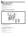
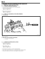
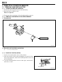
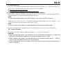
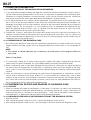
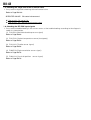
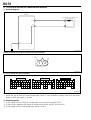
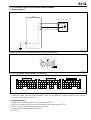
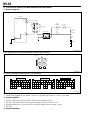
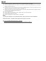
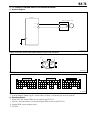
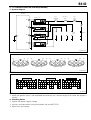
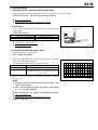
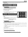
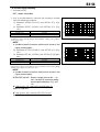
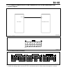
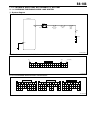
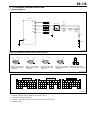
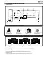
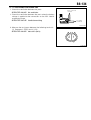
1 ENGINE CONTROL COMPUTER
1-1 REMOVAL AND INSTALLATION
1-1-1 OPERATION BEFORE REMOVAL
1. Disconnect the negative terminal of the battery.
2. Remove the No.2 instrument panel under cover.
Refer to Page I2-41.
3. Remove the glove compartment door Ay.
Refer to Page I2-38.
4. Disconnect the connectors of the engine control computer.
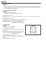
1-1-2 REMOVAL AND INSTALLATION PROCEDURES
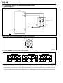
(1) Components
b
a
B
B
P21E6509S20
(2) Removal and installation procedures
1
2
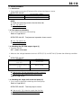
a Bracket, computer
b Computer Ay, fuel injection
1-1-3 OPERATION AFTER INSTALLATION
1. Connect the connectors of the engine control computer.
2. Attach the glove compartment door Ay.
Refer to Page I2-38.
3. Attach the No.2 instrument panel under cover.
Refer to Page I2-41.
4. Connect the negative terminal of the battery.
B8-2
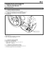
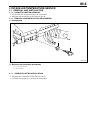
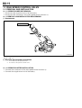
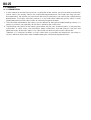
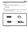
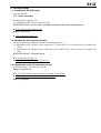
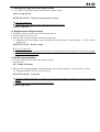
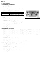
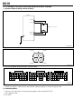
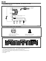
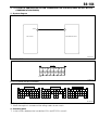
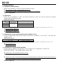
2 ENGINE REVOLUTION SENSOR
2-1 REMOVAL AND INSTALLATION
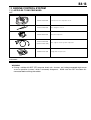
2-1-1 ARTICLES TO BE PREPARED
Lubricants,bonds,others
Engine oil
2-1-2 OPERATION BEFORE REMOVAL
1. Disconnect the negative terminal of the battery.
2. Disconnect the connector of the crank position sensor Ay.
2-1-3 REMOVAL AND INSTALLATION PROCEDURES
(1) Components
a
B
T:7.5&2.2 {76&22}
T11E6072S20
: Engine oil
Unit Nm {kgfcm}
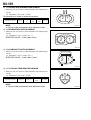
(2) Removal and installation procedures
1
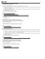
a Sensor Ay, crank position
2-1-4 POINTS OF INSTALLATION
(1) Sensor Ay, crank position
1. Apply engine oil to the O ring of the sensor Ay.
LUBRICANT: Engine oil
2-1-5 OPERATION AFTER INSTALLATION
1. Connect the connector of the crank position sensor Ay.
2. Install the negative terminal of the battery.
B8-3
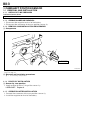
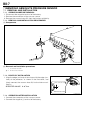
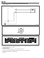
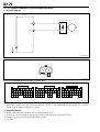
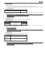
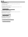
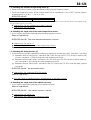
3 CAMSHAFT POSITION SENSOR
3-1 REMOVAL AND INSTALLATION
3-1-1 ARTICLES TO BE PREPARED
Lubricants,bonds,others
Engine oil
3-1-2 OPERATION BEFORE REMOVAL
1. Disconnect the negative terminal of the battery.
2. Disconnect the connector of the cam position sensor Ay.
3-1-3 REMOVAL AND INSTALLATION PROCEDURES
(1) Components
a
B
T:7.5&2.2 {76&22}
T11E6074S20
: Engine oil
Unit Nm {kgfcm}
(2) Removal and installation procedures
1
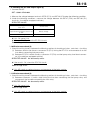
a Sensor Ay, cam position
3-1-4 POINTS OF INSTALLATION
(1) Sensor Ay, cam position
1. Apply engine oil to the O ring of the sensor Ay.
LUBRICANT: Engine oil
3-1-5 OPERATION AFTER INSTALLATION
1. Connect the connector of the cam position sensor Ay.
2. Install the negative terminal of the battery.
B8-4
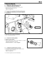
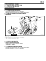
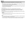
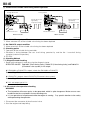
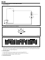
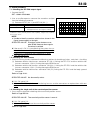
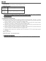
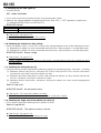
4 KNOCK SENSOR
4-1 REMOVAL AND INSTALLATION
4-1-1 OPERATION BEFORE REMOVAL
1. Disconnect the negative terminal of the battery.
2. Remove the intake manifold Ay.
Refer to Page B3-10.
3. Disconnect the connector of the knock control sensor.
4-1-2 REMOVAL AND INSTALLATION PROCEDURES
(1) Components
a
N
T:20.0&5.0 {204&50}
T11E6076S20
Unit: Nm {kgfcm}
(2) Removal and installation procedures
1
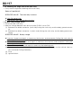
a Sensor, knock control
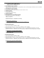
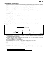
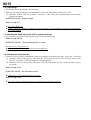
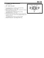
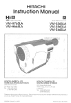
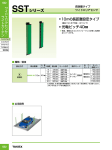
4-1-3 POINTS OF INSTALLATION
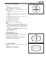
(1) Sensor, knock control
1. When attaching the sensor to the engine Ay, attach it
within the range shown in figure A.
SPECIFIED VALUE: A: 2015 degrees
Upper
A
P21E6515ET10
4-1-4 OPERATION AFTER INSTALLATION
1. Connect the connector of the knock control sensor.
2. Install the intake manifold Ay.
Refer to Page B3-10.
3. Install the negative terminal of the battery.
B8-5
5 ENGINE WATER TEMPERATURE SENSOR
5-1 REMOVAL AND INSTALLATION
5-1-1 OPERATION BEFORE REMOVAL
1. Disconnect the negative terminal of the battery.
2. Drain the cooling water.
Refer to Page B1-10.
3. Remove the engine Ay.
Refer to Page B2-23.
5-1-2 REMOVAL AND INSTALLATION PROCEDURES
(1) Components
~b
a
T:19.6&3.9 {200&40}
P21E6511S20
: Non-reusable parts
Unit: Nm {kgfcm}
(2) Removal and installation procedures
1
2
a Sensor, water temperature
b Gasket
5-1-3 OPERATION AFTER INSTALLATION
1. Install the engine Ay.
Refer to Page B2-23.
2. Fill cooling water.
Refer to Page B1-10.
3. Connect the negative (-) terminal of the battery.
4. Start the engine and perform air-bleeding of the cooling water.
5. Stop the engine and check for leakage of cooling water.
B8-6
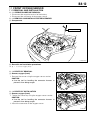
6 INTAKE AIR TEMPERATURE SENSOR
6-1 REMOVAL AND INSTALLATION
6-1-1 OPERATION BEFORE REMOVAL
1. Disconnect the negative terminal of the battery.
2. Remove the connectors of the thermo sensor.
6-1-2 REMOVAL AND INSTALLATION PROCEDURES
(1) Components
b
a
P21E6507S20
(2) Removal and installation procedures
1
2
a Sensor, thermo
b Grommet
6-1-3 OPERATION AFTER INSTALLATION
1. Connect the connectors of the thermo sensor.
2. Connect the negative (-) terminal of the battery.
B8-7
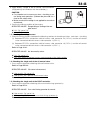
7 MANIFOLD ABSOLUTE PRESSURE SENSOR
7-1 REMOVAL AND INSTALLATION
7-1-1 OPERATION BEFORE REMOVAL
1. Disconnect the negative terminal of the battery.
2. Remove the connectors of the vacuum sensor.
3. Remove the vacuum hose S/A from the intake manifold Ay.
7-1-2 REMOVAL AND INSTALLATION PROCEDURES
(1) Components
a
b
P21E6510ES20
(2) Removal and installation procedures
1
2
a Sensor, vacuum
b Hose S/A, vacuum
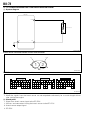
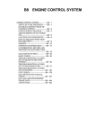
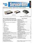
7-1-3 POINTS OF INSTALLATION
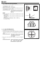
1. Align the edge (surface) of the clamp with the edge (surface) of the protector, as shown in the illustration, and
(then) connect the vacuum hose S/A to the intake manifold Ay.
SPECIFIED VALUE: A: 07
0mm
Hose S/A,vacuum
A
Manifold Ay,intake
P21E6514ET10
7-1-4 OPERATION AFTER INSTALLATION
1. Connect the connectors of the vacuum sensor.
2. Connect the negative (-) terminal of the battery.
B8-8
8 OIL CONTROL VALVE
8-1 REMOVAL AND INSTALLATION
8-1-1 ARTICLES TO BE PREPARED
Lubricant,adhesive,others
Engine oil
8-1-2 OPERATION BEFORE REMOVAL
1. Disconnect the negative terminal of the battery.
2. Remove the connectors of the cam timing oil control valve Ay.
8-1-3 REMOVAL AND INSTALLATION PROCEDURES
(1) Components
a
B
T:7.5&2.3 {76&22}
T11E6082S20
:Engine oil
Unit: Nm{kgfcm}
(2) RemovalRemoval and installation procedures
1
a Valve Ay, cam timing oil control
8-1-4 POINTS OF INSTALLATION
(1) Valve Ay, cam timing oil control
1. Apply engine oil to the O-ring of the valve Ay.
LUBRICANT: Engine oil
8-1-5 OPERATION AFTER INSTALLATION
1. Connect the connectors of the cam timing oil control valve Ay.
2. Connect the negative (-) terminal of the battery.
B8-9
9 THROTTLE POSITION SENSOR
9-1 REMOVAL AND INSTALLATION
9-1-1 OPERATION BEFORE REMOVAL
1. Disconnect the negative terminal of the battery.
2. Remove the air cleaner case.
Refer to Page B3-1.
3. Disconnect the connectors of the throttle position sensors.
9-1-2 REMOVAL AND INSTALLATION PROCEDURES
(1) Components
S
T:1.75&0.25 {17.8&2.5}
a
P21E6512ES20
Unit: Nm{kgfcm}
(2) Removal and installation procedures
1
a Sensor, throttle position
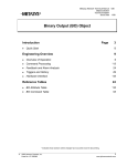
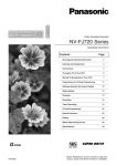
9-1-3 POINTS OF INSTALLATION
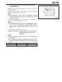
1. Confirm that the throttle valve is fully closed.
2. With the throttle valve turned 30 degrees to the left of the
fully-closed position, attach the throttle position sensor to
the throttle body.
3. Turn the throttle position sensor to the right, and attach it
with the 2 screws.
30 degrees
P21E6513ET10
B8-10
9-1-4 OPERATION AFTER INSTALLATION
1. Connect the connectors of the throttle position sensors.
2. Install the air cleaner case.
Refer to Page B3-1.
3. Connect the negative terminal of the battery.
B8-11
10 IDLE SPEED CONTROL VALVE
10-1 REMOVAL AND INSTALLATION
10-1-1 OPERATION BEFORE REMOVAL
1. Disconnect the negative terminal of the battery.
2. Disconnect the connectors of the idle speed control actuator Ay.
10-1-2 REMOVAL AND INSTALLATION PROCEDURES
(1) Components
S
T:1.75&0.25 {17.8&2.5}
S
a
~b
P21E6508ES20
: Non-reusable parts
Unit: Nm{kgfcm}
(2) Removal and installation procedures
1
2
a Actuator Ay, idle speed control
b Gascket, idle speed contorol valve
10-1-3 OPERATION AFTER INSTALLATION
1. Connect the connectors of the idle speed control actuator Ay.
2. Connect the negative terminal of the battery.
B8-12
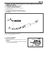
11 FRONT OXYGEN SENSOR
11-1 REMOVAL AND INSTALLATION
11-1-1 OPERATION BEFORE REMOVAL
1. Disconnect the negative terminal of the battery.
2. Disconnect the connector of the oxygen sensor.
11-1-2 REMOVAL AND INSTALLATION PROCEDURES
(1) Components
a
T:34.0&5.0 {347&50}
P21E6501ES20
Unit Nm {kgfcm}
(2) Removal and installation procedures
1
a Sensor, oxygen (front)
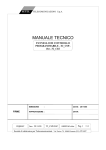
11-1-3 POINTS OF REMOVAL
(1) Sensor, oxygen (front)
1. Remove the sensor using the oxygen sensor socket.
CAUTION
Use the tool for handling the connector harness to
prevent it from being caught.
P21E6502T10
11-1-4 POINTS OF INSTALLATION
(1) Sensor, oxygen (front)
1. Tighten the sensor by using the oxygen sensor socket.
CAUTION
Use the tool for handling the connector harness to
prevent it from being caught.
2. Attach the connector of the oxygen sensor.
P21E6503T10
B8-13
11-1-5 OPERATION AFTER INSTALLATION
1. Install the negative terminal of the battery.
B8-14
12 REAR OXYGEN SENSOR(REAR OXYGEN SENSOR EQUIPPED
VEHICLES ONLY)
12-1 REMOVAL AND INSTALLATION
12-1-1 OPERATION BEFORE REMOVAL
1. Disconnect the negative terminal of the battery.
2. Lift up the vehicle.
3. Disconnect the connector of the oxygen sensor.
12-1-2 REMOVAL AND INSTALLATION PROCEDURES
(1) Components
a
T:34.0&5.0 {346&50}
P21E6504ES20
Unit Nm {kgfcm}
(2) Removal and installation procedures
1
a Sensor, oxygen (rear)
12-1-3 POINTS OF REMOVAL
(1) Sensor, oxygen (rear)
1. Remove the sensor by using the oxygen sensor socket.
CAUTION
Use the tool for handling the connector harness to
prevent it from being caught.
P21E6505T10
B8-15
12-1-4 POINTS OF INSTALLATION
(1) Sensor, oxygen (rear)
1. Tighten the sensor by using the oxygen sensor socket.
CAUTION
Use the tool for handling the connector harness to
prevent it from being caught.
P21E6506T10
12-1-5 OPERATION AFTER INSTALLATION
1. Connect the connector of the oxygen sensor.
2. Lift down the vehicle.
3. Install the negative terminal of the battery.
B8-16
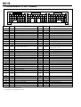
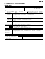
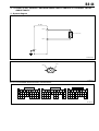
13 ENGINE CONTROL SYSTEM
13-1 ARTICLES TO BE PREPARED
SST
Shape
Part No.
Part name
09842-97209-000
Sub-harness, EFI computer check
09991-87403-000
Wire, diagnosis check
09842-30070-000
Wire, EFI inspection
09991-87404-000
(09991-87401-000)
09268-87701-000
Wire, engine control system inspection
Gauge, EFI fuel pressure
Instrument
Sound scope,Electrical tester,Oscilloscope,Diagnosis Tester
WARNING
Driving a vehicle with SST (EFI computer check subharness, etc.) being connected might cause
an error operation to occur, which is extremely dangerous. Make sure that SST has been disconnected before driving the vehicle.
B8-17
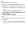
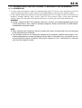
13-2 HANDLING INSTRUCTIONS OF CONTROL SYSTEM
13-2-1 HOW TO USE THE SERVICE MANUAL.
1. The method used for assignment of the diagnostic trouble codes and for displaying / erasing the
codes and the steps for checking are described together with the descriptions on the method of using the diagnosis tester or the OBD generic scan tool.
2. Carryout the troubleshooting by using a diagnosis tester or the OBD generic scan tool.
3. Diagnosis trouble codes are posted as both fourdigit code and twodigit code, for example, like
P0105/31.
(1) When only the diagnosis tester or the OBD generic scan tool is to be used, only fourdigit
codes are displayed.
(2) When the scan tool is not to be used, two-digit code (e.g. 31) will be displayed on the engine
check lamp.
NOTE
The OBD generic scan tool means a scan tool complying with the ISO 15765 format.
When the OBD generic scan tool is used, all malfunction codes (4-digit code) cannot be read out.
In this case, only the code which has zero after "P" (For example, P0XXX) can be read out.
The accuracy of the twodigit codes in diagnosing malfunctioning components is slightly inferior
to that of the fourdigit codes.
13-2-2 CAUTION WHEN CARRIED OUT A TROUBLESHOOTING
1. Do not disconnect the connector of EFI ECU, the battery cable from the battery, the ECU earth wire
from the engine, or the main fuse before the diagnosis information memorized in the ECU memory is
confirmed.
2. The diagnosis information memorized in the ECU memory can be erased by using the diagnosis
tester or the OBD generic scan tool in the same way as for checking of diagnosis trouble codes.
Therefore, before using the tester, carefully read its instruction manual to understand and familiarize
yourself with the functions provided and the method of using these functions.
3. Priority in troubleshooting
(1) If the priority in troubleshooting for a number of diagnostic trouble codes is given in the diagnosis code flow chart, be sure to carry out the troubleshooting by following the priority indicated.
(2) If the priority is not given, follow the priority given below and perform the troubleshooting for
each diagnostic trouble code.
(1) In the case of diagnosis trouble codes other than No. P0171/25, No. P0172/26 (too rich /too
lean in the fuel system).
(2) In the case of diagnosis trouble codes of No. P0171/25, No. P0172/26 (too rich /too lean in
the fuel system).
B8-18
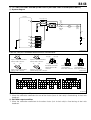
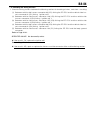
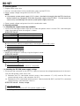
KEY switch
Engine
earth
Body
earth
Battery
*1: Immobilizer equipped vehicles
*2: Immobilizer non-equipped vehicles
*3: Rear oxygen sensor equipped vehicles
A/T
Refer to the wiring diagram for
the details of the air conditioner illumination.
11
45
42
93
43
133
119
DLC
OBD-@ connector
78
113
VF
PST
EFI(T SIO1
118
114
-+
64
102
101
Manifold absolute pressure sensor
65
Intake air temperature sensor
98
Water temperature sensor
21 131 133
62
99
Linear throttle sensor
Power steering oil pressure switch
To A
22
60
Rear oxygen sensor
Oxygen sensor heater
132
Front oxygen sensor
Knock sensor
100
106
IG2
69
55
STA
STA
7.5A
ACC
IG1
IG2
ST
For only A/T
Speed sensor
63
IG3
135
Transmission control switch
81
Engine
10A
Ignition coil 1
Starter relay
AM
50A
IG1
Ignition coil 2
Tail lamp
Engine revolution sensor
129
27
38
BAT
68
To
ignition plug
IG4
A
EFI
15A
Ignition coil 3
Clearance lamp
97
F/P motor
Starter
Meter illumination lamp
Cam angle sensor
130
50
M
47
Injector
REV
26
#1
SPD
PIM
E2PM
VCPM
25
#2
E2
N1(
N2(
OXH1
VC
PST
OX2*3
VTH THW THA
N2'
N1'
KNK OX1
24
#3
E1
18
#4
For only M/T
Tail lamp switch
Speed meter taco meter
EFI computer
61
IACA HI
Purge VSV
'B
67
66
IACA LO
E01
105
103
104
IACB HI
*1
IACB HI
FC3 #10 #20 #30 #40 PRG IACA HI
IACA LO
IACB LO
FC1*2
G
Stepper ISC
IACB LO
Ignition coil 4
Stop lamp lamp L
P/S OIL pressure switch
(Vehicles equipped with power steering)
ALT
IG
Main relay
Stop lamp switch
To B
Alternator
F/P relay
Stop lamp lamp R
23
Radiator fan
30A
M
Radiator fan motor
Radiator fan relay
Height mount stop lamp
To C
41
W
Magnet clutch relay
116 121 115
AUX ACSW ACEV
DEF
ACVR BLW
E21
13
94
MGC
54
FAN1
IG1/
back
7.5A
MGC
7.5A
Compressor
magnet clutch
Diagnosis lamp
STP
19
20
ECU IG2
10A
Oil control valve
H/L
A/B
ECU
B
44
Tail
lamp
10A
16
A/T
ECU
C
FPOF ATNE
OCV'
OCV(
Stop
lamp
10A
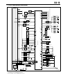
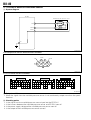
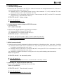
13-3 SYSTEM WIRING DIAGRAM
P21E6701S45
B8-19
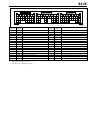
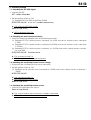
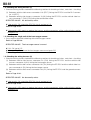
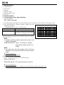
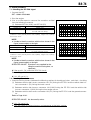
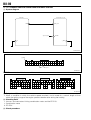
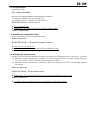
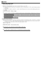
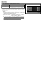
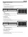
13-4 ARRANGEMENT OF ECU TERMINAL
27
26
25
24
23
22
21
20
19
18
17
16
15
14
13
12
11
10
9
8
69 68 67 66 65 64 63 62 61 60
59 58 57 56 55 54 53 52 51 50 49 48
106 105 104 103 102 101 100 99 98 97
96 95
94 93
92 91 90 89
88 87 86 85 84 83 82 81 80 79 78
133 132 131 130 129
128 127
126 125
124 123 122 121
120 119 118 117 116
135 134
47 46 45 44 43 42 41 40 39 38
115 114 113
W21E5146S10
Terminal Terminal
Terminal name
number
signal
8
9
10
11
DEF defo gger signal
12
13
W
Engine check lamp
14
15
16
ATNE
17
18
#40
Injector (#4)
19
OCV Oil control valve drive ()
20
21
22
23
24
25
26
27
38
39
40
41
42
43
44
OCV
OX1*1
OX1
E01
#30
#20
#10
B1
BAT
H/L
BLW
STP
FPOF
Oil control valve drive ()
Rear oxygen sensor
Front oxygen sensor
Power ground
Injector (#3)
Injector (#2)
Injector (#1)
EFI ECU power supply
Backup power supply
Tail lamp signal
Heater blower signal
Stop lamp signal
Airbag fuel pump "OFF" request shignal
Air conditioner evaporator temperature
45
ACEV
sensor
46
47
FC3*2 Fuel pump relay drive
48
49
50
FC1*3 Fuel pump relay drive
51
52
*1: Rear oxygen sensor equipped vehicles
*2: Immobilizer equipped vehicles
*3: Immobilizer non-equipped vehicles
Terminal Terminal
Terminal name
number
signal
53
54
FAN1 Radiator fan relay drive
55
STA
Starter signal
56
57
58
59
60
OXH1 Front oxygen sensor heater
61
PRG
Evaporative purge VSV
62
VC
Sensor power supply
63
N1
Engine speed sensor ()
Sensor earth (Exclusively used for mani64
E2PM
fold pressure sensor)
65
THA
Intake air temperature sensor
66
IACALO ISC stepper motor 1
67
IACAHI ISC stepper motor 2
68
IG4
Ignition coil (#4)
69
IG1
Ignition coil (#1)
78
VF
DLC (VF terminal)
79
80
81
A/T
Park/neutral position switch signal
82
83
84
85
86
87
88
89
90
91
92
93
94
95
ACSW
MGC
Air conditioner switch
Magnetic clutch relay drive
B8-20
27
26
25
24
23
22
21
69 68 67 66 65 64 63 62 61 60
20
19
18
17
16
15
14
59 58 57 56 55 54 53 52 51 50 49 48
13
12
11
10
9
8
47 46 45 44 43 42 41 40 39 38
106 105 104 103 102 101 100 99 98 97
96 95
94 93
92 91 90 89
88 87 86 85 84 83 82 81 80 79 78
133 132 131 130 129
128 127
126 125
124 123 122 121
120 119 118 117 116
135 134
115 114 113
W21E5146S10
Terminal Terminal
Terminal name
number
signal
96
97
N2 Camshaft position sensor ()
98
THW Coolant temperature sensor
99
VTH Throttle position sensor
100
N1 Engine speed sensor ()
101
VCPM
manifold pressure sensor power supply
102
PIM
manifold pressure sensor
103
IACBLO ISC stepper motor 3
104
IACBHI ISC stepper motor 4
105
ALT
Alternator cutoff control output
106
IG2
Ignition coil (#2)
113
EFI-T EFI-T check terminal
114
SPD Speed signal
115
ACVR A/C temperature adjustment volume
116
E21
Body sensor ground
117
SIO2*2 Immobilizer ECU
118
REV DLC (REV terminal)
*1: Rear oxygen sensor equipped vehicles
*2: Immobilizer equipped vehicles
*3: Immobilizer non-equipped vehicles
Terminal Terminal
Terminal name
number
signal
119
SIO1
DLC (SIO terminal)
120
121
122
123
124
125
126
127
128
129
N2
Camshaft position sensor ()
130
E1
Operation ground
131
E2
Sensor ground
132
KNK
Knock sensor
133
PST
Power steering oil pressure switch
134
135
IG3
Ignition coil (#3)
B8-21
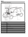
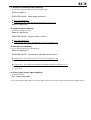
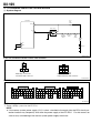
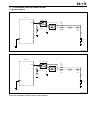
13-5 LOCATION OF COMPONENTS
r
d
f
l
e
k
i
j
b
o
c
q
m
n
a
f
g
h
P21E6709S30
Part name
a
Fuel pump
b
Engine control computer
c
Relay block
d
Cam angle sensor
e
Injector
f
Knock sensor
g
Front oxygen sensor
h
Engine coolant temperature sensor
i
ISC stepper motor
j
Throttle position sensor
k
Manifold absolute pressure sensor
l
Ignition coil
m
Oil control valve
n
Engine speed sensor
o
VSV control for evaporative purge
p
DLC
q
Intake air temperature sensor
r
Combination meter
t
Rear oxygen sensor*
*: Rear oxygen sensor equipped vehicles
B8-22
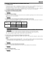
13-6 HOW TO PROCEED WITH TROUBLE SHOOTING
13-6-1 DESCRIPTION
1. The engine control system is equipped with diagnosis functions that are capable of diagnosing malfunctioning sections. These functions give important clues in troubleshooting.
2. The diagnosis function of this system is equipped with the battery backup (which keeps supplying
the power for diagnosis memory even when the IG switch is set to the "LOCK" position).
13-6-2 TROUBLE DIAGNOSIS PROCEDURE
1. Bringingin of malfunctioning vehicle
Go to 2.
2. Inquiry with the customer
1. Inquire the customer to obtain full information on the condition regarding how the failure occurred,
the environment, and the problem.
Go to 3.
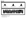
3. Confirmation and recording of the condition of the engine check lamp
1. Confirm and record the condition of how the engine check lamp is turned on when the IG switch is
set to "ON" and after the engine is started.
Engine check
lamp
When the IG
switch is set to
"ON"
Illuminated
Illuminated
Extinguished
After the engine
is started
Judgment
Extinguished
Illuminated
Extinguished
a
b
c
In the case of a, or b, go to 4.
In the case of c, carry out the following luck operations. If there is no problem, replace the combination meter.
(1) Check the harness and the connectors between the battery and combination meter.
(2) Check the harness and the connectors between the combination meter and EFI ECU.
(3) Check the power supply system and the earth system of EFI ECU
4. Confirmation and recording of the diagnosis trouble codes
1. Connect the diagnosis tester to the vehicle, and confirm and record the diagnosis code and the
freeze data.
NOTE
When shorting the terminals between EFIT (12) and E (4) of DLC, confirm and record the diagnosis code output to the engine check lamp within the combination meter.
Go to 5.
5. Confirmation of the malfunction phenomenon
1. Confirm the malfunction phenomenon and confirm the condition of the malfunction.
Go to 6.
6. Erasing diagnosis code
1. Carry out erasing of a diagnosis code.
Go to 7.
B8-23
7. Confirm reproduction of the malfunction phenomenon.
1. Confirm if it is possible to reproduce the malfunction phenomenon.
If the malfunction phenomenon could be reproduced, go to 8.
If the most function phenomenon could not be reproduced, go to 9.
8. Reconfirmation of the diagnosis code
1. Reconfirm the diagnosis code.
If an abnormal code is output, go to 10.
If a normal code is output, go to 9.
9. Basic check
1. Perform basic checks.
Refer to Page B8-34.
Go to 11.
10. Troubleshooting according to diagnosis codes
1. Carry out troubleshooting concerning the diagnosis code being output.
Refer to Page B8-41.
After the repair work is completed, go to 12.
11. Troubleshooting according to malfunction phenomena
1. Presume the cause of the malfunction phenomenon and carry out the troubleshooting accordingly.
Refer to Page B8-36.
After the repair is completed, go to 12.
12. Erasing the diagnosis code
1. Erase the diagnosis code.
Go to 13.
13. Confirmation and recording of the diagnosis code
1. Confirm and record the diagnosis code.
If a normal code is output, go to 14.
If an abnormal code is output, go back to 5 and carry out checking again.
B8-24
14. Confirmation test
1. Confirm if the malfunction phenomenon complained by the customer for a vehicle has been positively solved, and if the vehicle has returned to the normal condition.
If OK, terminate the work operation.
If NG, go back to 3 and carry out checking once again.
13-6-3 CONNECTING PROCEDURE FOR THE CHECK SUBHARNESS.
1. When the ECU terminal voltage is measured with the EFI ECU connector connected to the EFI ECU,
connect the SST by following the procedure given below.
NOTE
Each of the terminal number of the SST connector is the same as the ECU connector.
2. Set the ignition switch to "LOCK". Disconnect the battery ground cable from the negative () terminal of the battery with the ignition switch set to "LOCK".
NOTE
Be sure to record the diagnostic trouble code before disconnecting the battery cable.
3. Connect the following SST between the EFI ECU connector and the wire harness connectors.
SST: 09842-97209-000
4. Reconnect the battery ground cable to the negative () terminal of the battery.
CAUTION
When disconnecting the EFI ECU connectors, be sure to disconnect the negative () cable from
the battery with the ignition switch and all accessory switches are set to "LOCK".
When installing a new battery, care must be taken not to mistake the battery polarity. Failure to
observe this caution could cause an EFI ECU malfunction.
Before using the SST, be sure to check to see if short circuit or open wire exists between the terminals of the SST.
B8-25
13-7 INQUIRY
13-7-1 DESCRIPTION
1. In your attempt to remove the causes for a malfunction of the vehicle, you will not able to remove the
causes unless you actually confirm the malfunctioning phenomenon. No matter how long you continue operations, the vehicle may not resume the normal state unless you confirm the malfunctioning
phenomenon. The inquiry with the customer is a vital information collecting activity which is to be
conducted previous to the confirmation of malfunctioning phenomenon.
2. The information obtained by the inquiry can be referred to during the troubleshooting. Hence, it is
necessary to focus your questions on the items related to the malfunction.
3. The following main points of the inquiry given below are the most important points in analyzing the
malfunction. In some cases, the information about malfunctions that took place in the past and
about the history of previous repairs may seem to be not relative to the current malfunction.
Therefore, it is important to obtain as much information as possible and keep them accurately in
mind as reference information when troubleshooting the malfunctioning phenomenon.
B8-26
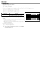
13-7-2 ENGINE CONTROL SYSTEM INQUIRY SHEET
[INQUIRY SHEET]
Name of customer
Frame No.
Vehicle model
Registration date
Inquiry sheet
Engine - N/A, T/C,
S/C, carburetor,
EFI, LPG
.
.
Date of malfunction
.
.
Transmission - 4M/T, 5M/T,
2WD, 4WD 2A/T, 3A/T,
4A/T
Running distance
km
Details Equipment:
of
vehicle [Sex] of customer (driver)
[Age]
[Occupation]
[Places where vehicle is mainly used] [Parking place]
Urban district/suburb/seacoast/mountain/others Outdoor/indoor
Approx.
Q Explosion is incomplete although initial explosion takes place.
Q No initial explosion takes place.
Q Hard starting (cold engine, hot engine, always)Q No cranking takes place0.
Poor starting
Q Other ( )
Q Idling speed too low
Q Fast idling ineffective
Q Idling unstable (cold engine, hot engine, always)
Q
Idling
speed
too
high
Faulty idling
Q Other ( )
Symptom
Q Hesitation (during start, during acceleration, during deceleration, during a certain period) Q Knocking
Q Backfire Q Lack of power Q Poor acceleration QPoor blow
Poor drive-ability
Q Other ( )
Q During idling (during warming up, after warming up) Q At time of starting QDuring running ( )
Q Immediately after vehicle stops (Re-start possible, Re-start impossible) QUnder loaded state (Air conditioner, electric load, power steering)
Engine stall
Q Other ( )
since what year/
month )
From when malfunction has started? Q Since vehicle was purchased as a new car QRecently (
Frequency of occurrence Q At all times Q Under a certain condition ( ) Q Sometimes
QAt all times
Meteorological
Q Fine Q Cloudy Q Rain Q Snow Q Other ( )
Weather
conditions
Temperature Q Temperature (about $C) (Spring, summer, autumn, winter)
Q When cold Q After warming-up QDuring warming-up (Coolant temperature about
$C)
Engine condition
QUrban district QSuburb QHighway QMountainous road (Uphill, downhill)
Road
QNo relation Q During racing under no load
Q During running (Vehicle speed:
km/h, Engine speed:
rpm, MT
Which gear?)
Driving conditions
Q During turn (right curve, left curve)
Male Female
Other situations
State of malfunction indicator lamp (MIL)
Indication of DTC
Q Reading out by using OBD @ generic
scan tool
Q Reading-out of MIL flashing pattern by
shorting terminal T
QIlluminated or flashing at all times Q Illuminated or flashing sometimes QWill not go on.
During checking QNormal Q Malfunction code ( )
2nd time
Q Normal QMalfunction code ( )
W21E5155ES40
B8-27
13-8 SYMPTOM CONFIRMATION
13-8-1 CONFIRMATION OF THE MALFUNCTION PHENOMENON
1. In carrying out the trouble shooting, the operator cannot find out the cause before actually conforming the malfunctioning phenomenon. For this end, it is imperative to reproduce the malfunction phenomenon by creating conditions and environments similar to the situation where the malfunction
took place, based on the information obtained by the diagnosis through inquiries.
2. As for the phenomenon that is difficult to be reproduced, it would be necessary to create the conditions similar to the running conditions under which the malfunction took place (road condition, meteorological condition and running condition), based on the information obtained by the diagnosis
through inquiries. For this purpose, it is most important to try to reproduce the phenomenon patiently by applying external factors, such as vibration (moving wire harnesses or relays by hand),
heat (applying hot wind) and water (giving humidity).
3. Furthermore, making a speculation on the possible section (part) that might have caused the malfunction and confirmation of the phenomenon by connecting and instruments such as a tester and
the like would provide an opportunity at the same time for making judgment of the conformance or
nonperformance of the section (part).
13-8-2 RECHECKING OF THE DIAGNOSIS CODE
1. By checking the diagnosis code after the malfunction phenomenon has been confirmed, it can be
judged whether the code system that was displayed before the confirmation is still acceptable or
not.
NOTE
The number of vehicle operation that is necessary for confirmation of the diagnosis differs for
every code.
Refer to Page B8-30.
2. If a malfunction should occur during checking and an abnormality code is displayed even after the
confirmation has been completed, carry out troubleshooting according to individual codes.
3. When no abnormal code is indicated, although the occurrence of malfunction was observed during
the confirmation of reproduction of malfunction, a malfunction other than those related to the diagnosis system is likely taking place. Proceed to the troubleshooting according to malfunctioning phenomena.
4. When no malfunction is observed during the confirmation of reproduction of malfunction, and the
normal code is indicated at the check of the DTC, it is presumed that an abnormality, such as poor
contacts at the harnesses and connectors, occurred in the past, but now they are functioning properly. Check the harnesses and connectors of those systems that was indicated before the confirmation of reproduction of the malfunctioning phenomenon.
13-9 CONFIRMATION, RECORD AND ERASURE OF DIAGNOSIS CODE
13-9-1 OUTLINE
1. When any abnormality code of the diagnosis is indicated, it is necessary to confirm the relationship
with the reproduced malfunction phenomenon by ascertaining whether the system malfunction has
occurred in the past or it still persists up to the present. To this end, the diagnosis code should be
indicated twice, i.e. before and after the confirmation of the phenomenon.
13-9-2 DIAGNOSIS CODE DISPLAY METHOD(INDICATION BY THE DIAGNOSIS TESTER)
1. Stop the vehicle.
2. After setting the ignition switch to "LOCK", connect the diagnosis tester to DLC.
3. After setting the ignition switch to "ON", use the diagnosis tester to read out the diagnosis code.
B8-28
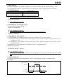
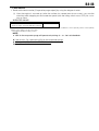
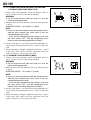
13-9-3 DIAGNOSIS CODE DISPLAY METHOD(INDICATION BY THE ENGINE CHECK LAMP)
1. Stop the vehicle.
2. Short the terminals 12(EFIT) and 4E of DLC by using the SST with the ignition switch set to "ON".
CAUTION
To short the terminals of DLC, be sure to use the specified SST.
Be sure to short the correct terminals. If wrong terminals are shorted, it will lead to malfunction.
SST: 09991-87403-000
09991-87404-000
NOTE
If the SST (engine control system inspection wire) is not to be used, carry out the work operation
by disconnecting DLC from the bracket. After the work operation is completed, make sure that
DLC is positively fastened to the bracket.
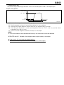
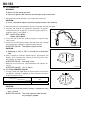
3. The engine check lamp within the combination meter will blink and the diagnosis codes will be indicated.
BAT
EFI-T REV
E
Engine check lamp
EFI-T terminal
Shorted
Open
Shorted
EFI-T terminal
0.25sec.
Illuminated
Engine check lamp
Extinguished
0.25sec.
Normal time
Open
0.5sec.
1.5sec.
Illuminated
Engine check lamp
Extinguished
4sec. 0.5sec.
4sec.
During abnormal period (In the case of Code No. 21)
W21E5154ES20
NOTE
All diagnosis codes that are stored in the memory will be displayed repeatedly in the order starting
from the smallest number.
B8-29
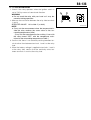
13-9-4 DIAGNOSIS CODE ERASE METHOD(ERASURE BY THE DIAGNOSIS TESTER)
NOTE
After checking and repairing points for which an abnormality code has been emitted, erase the
code in the ECU memory, following the procedure given below.
If an abnormally take code cannot be eraced, performed checking and repairing of points where
the abnormally codes occurred once again.
When erasure of abnormality codes is carried out, the freeze frame data are also eraced. Check in
advance if the erasure is permissible.
1. Stop the vehicle.
2. After setting the ignition switch to "LOCK", connect the diagnosis tester to the DLC.
3. After setting the ignition switch to "ON", use the diagnoses tester to erase the diagnosis codes.
13-9-5 DIAGNOSIS CODE ERASE METHOD(ERASURE BY DISCONNECTING THE FUSE)
1. Stop the vehicle.
2. Setting ignition switch to "LOOK", disconnect the EFI fuse by pulling it off for 60 seconds or more.
3. All codes stored in the memory can be erased by setting the ignition switch to "LOCK", and by disconnecting the EFI fuse for 60 seconds or more.
CAUTION
When disconnecting the backup fuse, output and confirm the diagnosis codes of other systems,
and then record it for the sake of the safety.
NOTE
As a rough standard, erasure can be achieved by disconnecting diffuse for approximately 60 seconds. In some cases, however, it may take more time.
Erasure can be also achieved by disconnecting the part supply from the battery, or the backup circuit such as fusible link. The time, however, in this case required for erasure will be longer.
B8-30
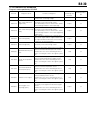
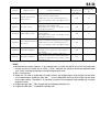
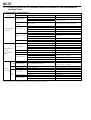
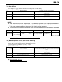
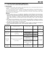
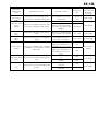
13-9-6 CONTENTS OF DIAGNOSIS
Diagnosis code specified by ISO/SAE
DTC No.
P0010/74
P0011/73
P0012/73
P0016/62
P0016/75
Diagnosis items
Contents of diagnosis
When an abnormality has occurred to the oil
control valve controlling voltage
When abnormalities take place two times consecutively in the valve timing control
VVT control :Advance
An abnormality in the oil control valve; admisangle faulty
sion of foreign matters in the oil passage
When abnormalities take place two times consecutively in the valve timing control
VVT control :Delay angle
An abnormality in the oil control valve; admisfaulty
sion of foreign matters in the oil passage(Delay
angle faulty)
When deviations between the camshaft position sensor signal and the engine rotation senChain timing faulty
sor signal are detected 5 times consecutively
Extension of the timing chain
When abnormalities take place two times conValve timing faulty
secutively in the valve timing control
Oil control valve system
P0105/31
Manifold absolute pressure
P0110/43
Intake air temperature
sensor
P0115/42
Coolant temperature
sensor(short,open)
P0120/41
Throttle sensor signal
P0130/21
Front oxygen sensor(range,open)
When an abnormality takes place in the signal
from the manifold absolute pressure sensor
Malfunction of a sensor, breaking of wire or
shortcircuiting of a wire in the signal system,
etc
When an abnormality takes place in the signal
from the intake temperature integral sensor
Malfunction of a sensor, breaking of wire or
shortcircuiting of a wire in the signal system,
etc
When malfunction takes place in the signal
from the coolant temperature sensor
Malfunction of a sensor, breaking of wire or
shortcircuiting of a wire in the signal system,
etc
When abnormality takes place in the signal
from the throttle position sensor
Malfunction of a sensor, breaking of wire or
shortcircuiting of a wire in the signal system,
etc
When abnormalities take place two times consecutively in the signal from the front oxygen
sensor
Malfunction of a sensor, breaking of wire or
shortcircuiting of a wire in the signal system,
etc
The method for
evaluating malfunctions
Warning indication
1trip
2 trips
2 trips
5 trips
2 trips
1 trip
1 trip
1 trip
1 trip
2 trips
B8-31
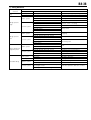
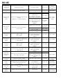
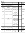
DTC No.
Diagnosis items
P0135/23
Front oxygen sensor
heater signal
P0136/22*1
P0171/25
P0172/26
P0325/18
P0335/13
P0340/14
P0350/16
P0443/76
Contents of diagnosis
When an abnormality takes place in the signal
from the front oxygen sensor heater
Breaking of wire or shortcircuiting of a wire
in the front oxygen sensor heater system
When abnormalities take place two times consecutively in the signal from the rear oxygen
sensor
Rear oxygen senMalfunction of a sensor, breaking of wire or
sor(range,open)
shortcircuiting of a wire in the signal system,
etc
When the airtofuel ratio deviates two times
consecutively to the lean side due to abnorFuel system (lean faulty) mality of the fuel trim system
Abnormal combustion pressure, injector,
oxygen sensor abnormal, etc
When the airtofuel ratio deviates two times
consecutively to the rich side due to abnormalFuel system (rich faulty) ity of the fuel trim system
Abnormal combustion pressure, injector,
oxygen sensor abnormal, etc
Vibrating-type knock
sensor signal
When abnormality takes place in the signal
from the knock sensor
Malfunction of a sensor, breaking of wire or
shortcircuiting of a wire in the signal system,
etc
When an abnormality takes place in the signal
from the engine revolution sensor
Camshaft position senMalfunction of a sensor, breaking of wire or
sor signal
shortcircuiting of a wire in the signal system,
etc
When malfunction takes place in the signal
from the camshaft position sensor
Camshaft position senMalfunction of a sensor, breaking of wire or
sor signal
shortcircuiting of a wire in the signal system,
etc
When the ignition signal is not input consecuIgnition system (Primary)
tively
When an abnormality takes place in the VSV
detection signal for the evaporator purging
Evaporator purge VSV
Breaking of wire or shortcircuiting of a wire
in the signal system, etc
The method for
evaluating malfunctions
Warning indication
1 trips
2 trips
2 trips
2 trips
1 trip
(Rear oxygen
sensor equipped
vehicles)
(Rear oxygen
sensor not
equipped vehicles)
1 trip
1 trip
1 trip
1 trips
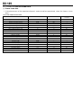
B8-32
DTC No.
P0500/52
P0505/71
P0512/54
P0535/44
P0603/83
U0167/81
Diagnosis items
Contents of diagnosis
When an abnormality takes place in the signal
from the vehicle speed sensor
Vehicle speed sensor
Malfunction of a sensor, breaking of wire or
signal system
shortcircuiting of a wire in the signal system,
etc
When malfunction takes place in the detection
signal for the ISC stepper motor
ISC valve system
Breaking of wire or shortcircuiting of a wire
in the signal system, etc
When an abnormality takes place in the signal
from the starter
Starter signal system
Breaking of wire or shortcircuiting of a wire
in the signal system, etc
When an abnormality takes place in the signal
from the evaporator temperature sensor signal
A/C evaporator temperaMalfunction of a sensor, breaking of wire or
ture sensor
shortcircuiting of a wire in the signal system,
etc
When a communication error with the immobiE2PROM Read/Write
lizer ECU occurs or when the code collation is
mismatched.
When collation of the collation code in the
communication with the immobilizer ECU due
E2PROM Read/Write
to an internal malfunction of the engine control
computer system
The method for
evaluating malfunctions
Warning indication
1 trip
1 trip
1 trip
1 trip
1 trip
1 trip
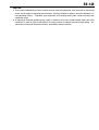
NOTE
Malfunction evaluation method: "1 trip" indicates the IG switch should be set to ON, the engine operated, and the IG switch set to LOCK. "2 trips" indicates this process should be repeated twice
and "5 trips" indicates the process should be repeated 5 times.
MIL: warning lamp
When the "O" mark is displayed in the MIL column, the engine check lamp will light up that diagnosis code number. However, when the "" mark is displayed, the lamp will not light up that diagnosis code number. Therefore, it is possible to read out the diagnosis code number by using the
diagnosis tester.
1
Diagnosis code with * : Rear oxygen sensor equipped vehicles only
2
Diagnosis code with * : immobilizer vehicles only
B8-33
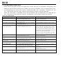
13-10 FAIL-SAFE FUNCTION
1. When abnormality takes place in the signal from various sensors, or malfunctions take place in the
control of the oil control valve for the variable valve timing, conditions such as engine failure, catalyst overheating may result, if the control is continued under such a condition. To prevent this, the
failsafe function uses the values stored in the computer in order to control operations.
When the malfunction is remedied to the normal condition after an abnormality was detected, the
failsafe control will be released. However, the diagnosis result will be stored in the memory.
List of fail safe function
Item
Failsafe execution conditions
Camshaft position sensor sys- When malfunction takes place in the signal
tem
from the camshaft position sensor
Knock sensor signal system
When abnormality takes place in the signal
from the knock sensor
Rear oxygen sensor system* When a malfunction occurs in the signal from
the rear oxygen sensor.
Manifold absolute pressure
When a malfunction occurs in the signal from
sensor signal system
the intake manifold pressure sensor.
FAILSAFE SPECIFICATIONS
The signal from the camshaft position sensor
is set to a constant value.
Ignition timing is retarded.
Set the feedback control to the open control.
The manifold absolute pressure is estimated
by the throttle opening angle and the engine
revolution speed. When abnormality occurs
in the signal from the throttle position sensor,
the signal from the manifold absolute pressure
sensor is set to the constant value.
If both the throttle opening angle and engine
speed exceed their set values, the fuel is cut.
Throttle position sensor sysWhen abnormality takes place in the signal
The signal from the throttle position sensor is
tem
from the throttle position sensor
set to a constant value.
Coolant temperature sensor
When malfunction takes place in the signal
The signal from the water temperature sensor
system
from the coolant temperature sensor
is set to a constant value.
Intake air temperature sensor When a malfunction occurs in the signal from The signal from the intake temperature sensor
signal system
the intake air temperature sensor.
is set to a constant value.
A/C evaporator temperature
When malfunction takes place in the signal
The air conditioner is shut down.
sensor signal system
from the A/C evaporator temperature sensor
Valve timing system
When abnormalities take place two times
The valve timing is set to the most retarded
consecutively in the valve timing control
position.
Stepper motor system for ISC When an abnormal signal occurred in the
Cut off the energizing control for the stepper
stepper motor for ISC
motor for ISC.
Cut off the fuel injection
Oil control valve system
When malfunction takes place in the control Prohibit the oil control valve energizing convoltage for the oil control valve
trol.
*: Rear oxygen sensor equipped vehicles
B8-34
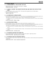
13-11 BASIC CHECK
13-11-1 MEASUREMENT OF THE BATTERY VOLTAGE
1. Measure the battery voltage when the engine is stopped.
SPECIFIED VALUE: 12 to 14V
13-11-2 VISUALLY INSPECT THE CONNECTOR SECTIONS AND CHECK THE CONTACT PRESSURE.
1. After the ignition switch is set to "LOCK", disconnect the negative terminal of the battery.
2. Check the connector of EFI ECU.
Refer to Page A1-32.
13-11-3 POWER SUPPLY CIRCUIT CHECK
1. Disconnect the connector of EFI ECU, and measure the voltage between the connector terminal on
the next ECU connection vehicle harness side and the body earth of the vehicle.
(1) Between the ECU connected vehicle harness side connector 38 (BAT) terminal and the body
earth.
SPECIFIED VALUE: Battery voltage
13-11-4 EARTH CIRCUIT CHECK
1. Set the ignition switch to "LOCK" and disconnect the battery negative terminal.
2. Disconnect the connector of EFI ECU, and confirm the continuity between the connector terminal on
the next ECU connection vehicle harness side and the body earth of the vehicle.
(1) Between the ECU connected vehicle harness side connector 23 (E01) terminal and the body
earth.
(2) Between the ECU connected vehicle harness side connector 130 (E1) terminal and the body
earth.
SPECIFIED VALUE: Continuity exists
13-11-5 CHECKING THE INJECTOR OPERATION.
1. Use a sound scope or a long screw driver to check the injector's operating sound.
SPECIFIED VALUE: Operating sound is provided
13-11-6 CHECKING THE FUEL PRESSURE (SIMPLE).
1. Start the engine. Pinch the fuel hose with your finger and confirm that the fuel pressure (pulsation)
can be felt.
SPECIFIED VALUE: Hose is under the fuel pressure
B8-35
13-11-7 SPARK CHECK
WARNING
The inspection will cause sparks to be generated, which is quite dangerous. Make sure no combustible materials are placed in the surrounding area.
1. Warm up the engine.
2. Perform fuel pressure release operation.
Refer to Page B7-1.
3. Set the ignition switch to "LOCK".
4. Disconnect all injector connectors.
CAUTION
This step will terminate fuel injection and prevent damage to the catalytic converter from uncombusted gas.
5. Remove the spark plug. Attach it to the ignition coil and ground the plug
6. Check if the spark plug generates sparks when cranking is performed.
SPECIFIED VALUE: Sparks are generated
B8-36
13-12 TROUBLE SHOOTING ACCORDING TO MALFUNCTION PHENOMENA
13-12-1 DESCRIPTION
1. In cases where no diagnosis code was detected during the DTC check and malfunction can be still
confirmed during the basic check, perform the troubleshooting, referring to the following table.
2. In the trouble shooting according to malfunction phenomena, first arrange in order of the contents of
diagnosis through inquiries, basic checks and ECU circuit checks. Next, narrow down possible
causes, referring to the table showing possible causes according to malfunction phenomena.
WARNING
Driving a vehicle with SST (EFI computer check subharness, etc.) being connected might cause
an error operation to occur, which is extremely dangerous. Make sure that SST has been disconnected before driving the vehicle.
NOTE
When checking each component, be sure to check the harness and connectors that are connected
to the component part concerned.
Two possible causes for no abnormality detected by the diagnosis function even though a malfunction phenomenon has been reproduced can be cited: it is possible that a malfunction has occurred outside the scope of diagnosis code output condition; or that a malfunction has occurred
apart from the diagnosis system.
B8-37
13-12-2 TABLE FOR THE LIST OF POSSIBLE CAUSES ACCORDING TO THE PHENOMENA OF
MALFUNCTIONS
(1) Poor starting characteristics
Malfunction phenomena
System
Power supply
system
Engine earth
system
No initial ignition
produced
Fuel system
Ignition system
Possible causes
Components
EFI ECU power supply circuit
IG switch
Main relay
Malfunction mode
Breaking of wires, shortcircuits
No turning "ON"
Engine earth*1
Breaking of wires, defective earth
Fuel pump relay
Fuel line, Fuel filter
Injector
Fuel pump
Engine fuse*1
Ignition coil
Spark plug
Ignition timing
Engine speed sensor
Camshaft position sensor
Fuel pump relay
Fuel line, Fuel filter
Injector
Fuel pump
Spark plug
Air hose, etc.
manifold pressure sensor
Coolant temperature sensor
Camshaft position sensor
Oil control valve
Throttle body
No turning "ON"
Clogging
No injection, always injection
No operation
Fuse meltdown
No spark
Misalignment
No "NE signal" output
Control system
Defective output signal
No turning "ON"
Clogging
Fuel system
Leakage, no injection, always injection
No operation
Initial ignition ocIgnition system
Misfire
curring
No complete
Intake system
Leak
ignition
Deviation in the characteristics, breaking
the liars, shortcircuiting
Control system
Output signal defective
Defective operation
Intake system
Defective opening, no opening possible
cold
Deviation in the characteristics, breaking
period Control system
Coolant temperature sensor
the liars, shortcircuiting
Hot
Fuel system
Injector
Leak
period Intake system
ISC stepper motor
Defective opening, no opening possible
Difficulty
Fuel pump relay
No turning "ON"
in starting
Fuel system
Fuel line, Fuel filter
Clogging
At all
Injector
Leak
times Ignition system
Spark plug
Smoldering
ISC stepper motor
Defective opening
Intake system
Air hose, etc.
Leak
*1:If the ignition switch is set to "ON" when the connection between the engine earth (between 130 (E1) connecting earth and
the engine block) is defective, the "E/G fuse" may sometimes melt down.
B8-38
(2) Idling defective
Malfunction phenomena
System
Fast idle not work- Intake system
ing
Control system
Intake system
Idling speed is
high
Control system
Intake system
Idling speed is
low
Control system
Intake system
When idling hunting takes place
Control system
Fuel system
Intake system
Unstable idling
Ignition system
Control system
Possible causes
Components
ISC stepper motor
Coolant temperature sensor
Air hose, etc.
Throttle body
ISC stepper motor
Manifold absolute pressure sensor
Coolant temperature sensor
Throttle position sensor
Stop lamp switch
Tail lamp switch
Blower switch
Air hose, etc.
Throttle body
Manifold absolute pressure sensor
Coolant temperature sensor
Stop lamp switch
Tail lamp switch
Blower switch
Air hose, etc.
Throttle body
ISC stepper motor
Manifold absolute pressure sensor
Camshaft position sensor
Oil control valve
Injector
Fuel pump
Throttle body
Ignition coil
Spark plug
Manifold absolute pressure/ intake temperature integral sensor
Front oxygen sensor, Rear oxygen sensor
Malfunction mode
Defective opening, no opening possible
Breaking of wires, shortcircuits
Leak
Closing defective
Always open
Deviation in the characteristics, breaking
the liars, shortcircuiting
Deviation in the characteristics
Always "ON"
Clogging
Deviation in the characteristics
No turning "ON"
Leak
Always open
Deviation in the characteristics
Output signal defective
Operation defective
Leakage, no injection
Operation defective
Sucking in
Poor contacting
Misfire
Defective operation, defective contact
B8-39
(3) Engine stalled
Malfunction phenomena
System
Fuel system
After starting the
engine, it stops
Control system
The engine stalls
when pressing on Control system
the accelerator
The engine stalls
when releasing
the accelerator
Engine stops
when the air conditioner is turned
on.
Possible causes
Components
Fuel pump relay
Fuel line, Fuel filter
Fuel pump
Coolant temperature sensor
Camshaft position sensor
Oil control valve
Malfunction mode
No turning "ON"
Clogging
No operation
Deviation in the characteristics
Output signal defective
Operation defective
Deviation in the characteristics
Intake system
Coolant temperature sensor
Camshaft position sensor
Oil control valve
Throttle body
Output signal defective
Operation defective
Operation defective
Control system
manifold pressure sensor
Deviation in the characteristics
Intake system
ISC stepper motor
Constantly closed
Power supply
system
Engine stops, but
Intake system
can be restarted.
Ignition system
Control system
EFI ECU power supply circuit
IG switch
Main relay
ISC stepper motor
Ignition coil
manifold pressure sensor
Engine speed sensor
Poor contacting
Constantly closed
Poor contacting
Poor contacting
B8-40
(4) Defective running
Malfunction phenomena
System
Fuel system
Takes a pause
when accelerating.
Ignition system
Control system
Fuel system
Ignition system
Back fire
After fire
Control system
Fuel system
Engine output
insufficient
Ignition system
Control system
Fuel system
Black smoke emitted
Control system
Fuel system
Hunting carried
Ignition system
out during running
Control system
Possible causes
Components
Fuel line, Fuel filter
Injector
Fuel pump
Ignition coil
Spark plug
Ignition timing
Coolant temperature sensor
Throttle position sensor
Knock sensor
Injector
Ignition coil
Spark plug
Ignition timing
SB08_EF_D99BE1_0338
Coolant temperature sensor
Camshaft position sensor
Oil control valve
Fuel line, Fuel filter
Injector
Fuel pump
Spark plug
manifold pressure sensor
Coolant temperature sensor
Throttle position sensor
Camshaft position sensor
Oil control valve
Injector
manifold pressure sensor
Coolant temperature sensor
Throttle position sensor
Fuel line, Fuel filter
Injector
Ignition coil
Throttle position sensor
Camshaft position sensor
Oil control valve
manifold pressure sensor
Abnormal knocking takes place
Control system
Throttle position sensor
Knock sensor
Malfunction mode
Clogging
Declining of the flow rate
Missing ignition
Misfire
Misalignment
Deviation in the characteristics, breaking
of wire, shortcircuiting
Breaking of wires, shortcircuits
Declining of the flow rate
Poor contacting
Misfire
Misalignment
Operation defective
Deviation in the characteristics
Output signal defective
Operation defective
Fuel pressure not increased
Declining of the flow rate
Fuel pressure not increased
Misfire
Deviation in the characteristics, breaking
of wire, shortcircuiting
Deviation in the characteristics
Output signal defective
Operation defective
Always injection
Deviation in the characteristics, breaking
of wire, shortcircuiting
Deviation in the characteristics
Clogging
Operation defective
Poor contacting
Deviation in the characteristics
Output signal defective
Operation defective
Deviation in the characteristics, breaking
of wire, shortcircuiting
Deviation in the characteristics
Deviation in the characteristics, breaking
of wire, shortcircuiting
B8-41
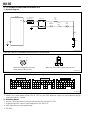
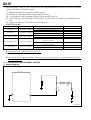
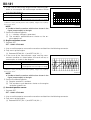
13-13 TROUBLE SHOOTING ACCORDING TO DIAGNOSIS CODE
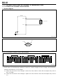
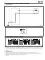
13-13-1 P0010/74 OIL CONTROL VALVE SYSTEM
(1) System diagram
EFI ECU
OCV' 20
1
Oil control valve
2
OCV( 19
130 E1
W21E5104ES20
Oil control valve connected vehicle harness side connector
OCV(
OCV'
1 2
H11E6067S10
EFI ECU connection vehicle harness side connector
8
9
10
11
12
13
38 39 40 41 42 43 44 45 46 47
14
15
16
17
18
19
20
48 49 50 51 52 53 54 55 56 57 58 59
78 79 80 81 82 83 84 85 86 87 88
89 90 91 92
93 94
95 96
113114 115
121122 123124
125126
127 128
116117 118119 120
21
22
23
24
25
26
27
60 61 62 63 64 65 66 67 68 69
97 98 99 100101102 103104 105106
129130 131132 133
134135
W21E5145S10
(2) Output conditions
1. When either of the following conditions lasted for a certain length of time or longer with the battery
voltage maintained at 12 V or higher
(1) When the oil control valve voltage is lower than the criterion value with the output duty ratio at
99% or higher
(2) When the oil control valve voltage is higher than the criterion value with the output duty ratio at
0%
B8-42
(3) Checking points
1. Oil control valve signal output by the EFI ECU.
2. Harness and connector(s) linking the oil control valve and the EFI ECU.
3. EFI ECU
(4) Checking method
1. Diagnosis code checking
1. Use diagnosis tester to read out the diagnosis code.
SPECIFIED VALUE: P0016/62 (Chain timing control system) is not output.
If it is output, check the timing chain for extension.
If it is not output, go to 2.
2. Data monitor (1)
1. Warm up the engine.
2. Use diagnosis tester to read out the data monitor [Target angle of intake cam] and [Actual angle of
intake cam].
SPECIFIED VALUE: While the vehicle is running, the real displacement angle will vary by following
the target displacement angel.
If the result is OK, it is possible that the system has returned to the normal condition.
leave the system as it is to observe the condition for a while.
If the result is NG, go to 3.
Therefore,
3. Data monitor (2)
1. Warm up the engine.
2. Use diagnosis tester to read out the data monitor [VVT control duty ratio].
SPECIFIED VALUE:
The engine condition
Displayed data
The air conditioner is turned "OFF": no electric
30 to 55%
load applied; when the engine is "idling."
The condition under which the air conditioner is turned "OFF": the air conditioner switch (ASCW), blower switch (BLW), magnet clutch (MGC) are all set to "OFF".
If the result is OK, go to 4.
If the result is NG, check the EFI ECU circuit.
Refer to Page A1-32.
4. Checking the wiring harness
1. Check the wiring harness between the following sections for breaking of wires, and shortcircuiting.
(1) Between EFI ECU connection vehicle harness side connector 20 (OCV) and the oil control
valve connected vehicle harness side connector 1 (OCV).
(2) Between EFI ECU connection vehicle harness side connector 19 (OCV) and the oil control
valve connected vehicle harness side connector 2 (OCV).
SPECIFIED VALUE: No abnormality exists.
If it is OK, go to 5.
If it is "NG" repair or replace harness and connector at the faulty section.
B8-43
5. Checking the single unit of the oil control valve
1. Carry out the single unit checking of the oil control valve.
Refer to Page B8-133.
SPECIFIED VALUE: Oil control valve normal.
If the result is OK, go to 6.
If the result is NG, replace the oil control valve.
6. Checking the EFI ECU input signals
1. Carry out the troubleshooting in the same manner as the troubleshooting according to the diagnosis
codes as shown below.
(1) P0105/31 (Manifold absolute pressure signal)
Refer to Page B8-49.
(2) P0115/42 (Coolant temperature sensor(short,open))
Refer to Page B8-53.
(3) P0120/41 (Throttle sensor signal)
Refer to Page B8-56.
(4) P0335/13 (Engine revolution sensor signal)
Refer to Page B8-76.
(5) P0340/14 (Camshaft position
Refer to Page B8-79.
sensor signal)
B8-44
13-13-2 P0011/73 VVT CONTROL :ADVANCE ANGLE FAULTY,P0012/73 VVT CONTROL :DELAY
ANGLE FAULTY
(1) System diagram
EFI ECU
OCV' 20
1
Oil control valve
2
OCV( 19
130 E1
W21E5104ES20
Oil control valve connected vehicle harness side connector
OCV(
OCV'
1 2
H11E6067S10
EFI ECU connected vehicle harness side connector
8
9
10
11
12
13
38 39 40 41 42 43 44 45 46 47
14
15
16
17
18
19
20
48 49 50 51 52 53 54 55 56 57 58 59
78 79 80 81 82 83 84 85 86 87 88
89 90 91 92
93 94
95 96
113114 115
121122 123124
125126
127 128
116117 118119 120
21
22
23
24
25
26
27
60 61 62 63 64 65 66 67 68 69
97 98 99 100101102 103104 105106
129130 131132 133
134135
W21E5145S10
B8-45
(2) Outline of the variable valve timing control operation
Timing advanced
Timing retard
Oil pressure
Timing advanced
signal Duty
comparison:large
Oil pressure
P
Movement of OCV
DVVT controller
Timing advanced
signal Duty
comparison:small
P
Movement of OCV
DVVT controller
M31E8311ES15
(3) No. P0011/73 output condition
1. When advance fail, of the variable valve timing has been depicted
(4) No. P0012/73 output condition
1. When retard fail, of the variable valve timing has been depicted
(5) Checking points
1. Operation of the variable timing controller.
2. Deviation in timing between the cam shaft timing sprocket Ay and the No. 1 camshaft timing
sprocket (matchmark position).
3. EFI ECU
(6) Checking Method
1. Diagnosis code checking
1. Read out the diagnosis code by using the diagnosis tester.
SPECIFIED VALUE: P0016/62 (Chain timing faulty), P0016/75 (Valve timing faulty) and P0010/74
(Oil control valve system) is not output.
If P0016/62 or P0016/75 is output, check the P0016/62 or P0016/75.
Refer to Page B8-48.
If P0010/74 is output, check P0010/74 (Oil control valve system).
Refer to Page B8-41.
If it is not output, go to 2.
2. Oil control valve operation checking
WARNING
The inspection will cause sparks to be generated, which is quite dangerous. Make sure no combustible materials are placed in the surrounding area.
It is an operation to be performed while the engine is running. Pay special attention to the safety
while performing the operation.
1. Disconnect the connector of the oil control valve.
2. Start the engine and keep idling.
B8-46
3. Apply battery voltage to the oil control valve connector.
(Align polarity of connector with that of battery.)
CAUTION
Pay attention not to cause any shortcircuiting to occur during work operation. (Connect the plus side via a
2
1
fuse for the safety sake.)
Make sure that the voltage is not applied for more than
one minute.
4. Confirm the idling condition of the engine.
W21E5105T10
SPECIFIED VALUE: Rough idling or stalling of the engine occurs.
If it is OK, go to 3.
If it is NG, go to 4.
3. Checking the wiring harness
1. Check the wiring harness between the following sections for breaking of wires, and shortcircuiting.
(1) Between EFI ECU connection vehicle harness side connector 20 (OCV) and the oil control
valve connected vehicle harness side connector 1 (OCV).
(2) Between EFI ECU connection vehicle harness side connector 19 (OCV) and the oil control
valve connected vehicle harness side connector 2 (OCV).
Refer to Page A1-31.
SPECIFIED VALUE: No abnormality exists.
If it is OK, go to 7.
If it is "NG" repair or replace harness and connector at the faulty section.
4. Checking the single unit of the oil control valve
1. Carry out the single unit checking of the oil control valve.
Refer to Page B8-133.
SPECIFIED VALUE: Oil control valve normal.
If the result is OK, go to 5.
If the result is NG, replace the oil control valve.
Refer to Page B8-8.
5. Checking the single unit of the DVVT controller
1. Carry out the single unit checking of the camshaft timing sprocket Ay.
Refer to Page B2-14.
SPECIFIED VALUE: Cam shaft timing sprocket Ay normal.
If the result is OK, go to 6.
If the result is NG, replace the camshaft timing sprocket Ay.
Refer to Page B2-14.
B8-47
6. Oil passage checking
1. Check the passage of the engine oil.
SPECIFIED VALUE: No clogging
If the result is OK, go to 7.
If the result is NG, repair the malfunctioning section of the oil passage.
7. Camshaft gear deviation checking
1. Inspect deviation between the cam shaft timing sprocket Ay and the No. 1 camshaft timing sprocket
(using the matchmark positions).
SPECIFIED VALUE: No deviation existing.
If the result is OK, check the EFI ECU circuit.
Refer to Page A1-32.
If the result is NG, reassemble the camshaft.
Refer to Page B2-14.
B8-48
13-13-3 P0016/62 CHAIN TIMING FAULTY
P0016/75 VALVE TIMING FAULTY
(1) No. P0016/62 output condition
1. When deviations between the camshaft position sensor and the engine revolution sensor have been
detected 5 times consecutively
(2) No. P0016/75 output condition
1. Inspect when valve timing control errors occur twice in a row.
(3) Checking points
1. Timing chain stretch.
2. Timing chain for assembling.
(4) Check procedure
1.Timing chain for assembling checking
1. Check the timing chain for assembling
Refer to Page B2-7.
SPECIFIED VALUE: Assemble is not wrong.
If the result is OK, go to 2.
If the result is NG, reassemble the timing chain and go to 3.
Refer to Page B2-7.
2.Confirmation test (1)
1. Carry out erasing of a diagnosis code.
2. Start the engine and warm it up until the radiator fan starts rotating.
3. Read the diagnosis code, using the diagnosis tester or an OBD general-purpose scan tool
SPECIFIED VALUE: P0016/62 (Chain timing faulty) or P0016/75 (Valve timing faulty) not output
If the result is OK, end of trouble shooting .
If the result is NG, check the EFI ECU circuit.
Refer to Page A1-32.
3.Confirmation test (2)
1. Carry out erasing of a diagnosis code.
2. Start the engine and warm it up until the radiator fan starts rotating.
3. Read the diagnosis code, using the diagnosis tester or an OBD general-purpose scan tool
SPECIFIED VALUE: P0016/62 (Chain timing faulty) or P0016/75 (Valve timing faulty) not output
If the result is OK, end of trouble shooting .
If the result is NG, replace the timing chain.
Refer to Page B2-7.
B8-49
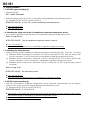
13-13-4 P0105/31 MANIFOLD PRESSURE SENSOR
(1) System diagram
EFI ECU
Manifold absolute pressure sensor
PIM 102
1
VCPM 101
3
E2PM
130
2
+
-
64
E1
P21E6703S20
manifold pressure sensor vehicle harness connector
E2PM
PIM
VCPM
1 2 3
H11E6020S10
EFI ECU vehicle harness connector
8
9
10
11
12
13
38 39 40 41 42 43 44 45 46 47
14
15
16
17
18
19
20
48 49 50 51 52 53 54 55 56 57 58 59
78 79 80 81 82 83 84 85 86 87 88
89 90 91 92
93 94
95 96
113114 115
121122 123124
125126
127 128
116117 118119 120
21
22
23
24
25
26
27
60 61 62 63 64 65 66 67 68 69
97 98 99 100101102 103104 105106
129130 131132 133
134135
W21E5145S10
(2) Output conditions
1. When the signal from the manifold pressure sensor is not continuously output more than the specified time.
(3) Checking points
1. Is the signal from the manifold pressure sensor input into the EFI ECU?
2. Is the harness between the manifold pressure sensor and EFI ECU normal?
3. Is the power supply voltage of the manifold pressure sensor normal?
4. Is the output of the manifold pressure sensor correct?
B8-50
(4) Checking method
1. Checking the EFI ECU signal
1. Connect the SST.
SST: 09842-97209-000
2. Set the ignition switch to "ON"
(1) Between SST102 (PIM) and SST64 (E2PM)
SPECIFIED VALUE: 3.1 to 4.1 V (ambient temperature)
If OK, check the EFI ECU circuit.
Refer to Page A1-32.
If NG, proceed to step 2.
2. Checking the wire harness continuity
1. Check the continuity between each of the following terminals.
(1) Between EFI ECU vehicle harness connector 102 (PIM) and sensor vehicle harness connector
2 (PIM)
(2) Between EFI ECU vehicle harness connector 64 (E2PM) and sensor vehicle harness connector
1 (E2PM)
(3) Between EFI ECU vehicle harness connector 101 (VCPM) and sensor vehicle harness connector 3 (VCPM)
SPECIFIED VALUE: Continuity exists.
If OK, proceed to step 3.
If NG, repair the harnesses and connectors.
3. Checking the manifold pressure sensor voltage
1. Disconnect the manifold pressure sensor connector.
2. Set the ignition switch to "ON"
(1) Between sensor vehicle harness connector 3 (VCPM) and sensor vehicle harness connector 1
(E2PM)
SPECIFIED VALUE:
If OK, proceed to step 4.
If NG, check the EFI ECU circuit.
Refer to Page A1-32.
4. Checking the manifold pressure sensor
1. Check the manifold pressure sensor.
Refer to Page B8-128.
If OK, check whether each connector is properly connected.
If NG, replace the manifold pressure sensor.
B8-51
13-13-5 P0110/43 INTAKE AIR TEMPERATURE SENSOR
(1) System diagram
EFI ECU
Intake temperature integral sensor
THA 65
E2
130
1
131
2
E1
P21E6704S20
Intake air temperature sensor vehicle harness connector
THA
E2
1
2
H11E6026S10
EFI ECU vehicle harness connector
8
9
10
11
12
13
38 39 40 41 42 43 44 45 46 47
14
15
16
17
18
19
20
48 49 50 51 52 53 54 55 56 57 58 59
78 79 80 81 82 83 84 85 86 87 88
89 90 91 92
93 94
95 96
113114 115
121122 123124
125126
127 128
116117 118119 120
21
22
23
24
25
26
27
60 61 62 63 64 65 66 67 68 69
97 98 99 100101102 103104 105106
129130 131132 133
134135
W21E5145S10
(2) Output conditions
1. When the signal from the intake temperature sensor is not continuously output more than the specified time after the engine is started.
(3) Checking points
1. Is the signal from the intake air temperature sensor input into the EFI ECU?
2. Is the harness between the intake air temperature sensor and EFI ECU normal?
3. Is the output of the intake temperature sensor correct?
B8-52
(4) Checking method
1. Checking the EFI ECU signal
1. Connect the SST.
SST: 09842-97209-000
2. Set the ignition switch to "ON"
(1) Between SST65 (THA) and SST131 (E2)
SPECIFIED VALUE: 0.15 to 4.85 V (changes according to the intake air temperature)
If OK, check the EFI ECU circuit.
Refer to Page A1-32.
If NG, proceed to step 2.
2. Checking the wire harness continuity
1. Check the continuity between each of the following terminals.
(1) Between sensor vehicle harness connector 1 (THA) and EFI ECU vehicle harness connector 65
(THA)
(2) Between sensor vehicle harness connector 2 (E2) and EFI ECU vehicle harness connector 131
(E2)
SPECIFIED VALUE: Continuity exists.
If OK, proceed to step 3.
If NG, repair the harness and connectors.
3. Checking the intake air temperature sensor
1. Check the intake air temperature sensor.
Refer to Page B8-129.
If OK, check whether each connector is properly connected.
If NG, replace the intake air temperature sensor.
Refer to Page B8-6.
B8-53
13-13-6 P0115/42 COOLANT TEMPERATURE SENSOR(SHORT,OPEN)
(1) System diagram
EFI ECU
Engine coolant temperature sensor
THW 98
E2
130
1
131
2
E1
W21E5108ES20
Water temperature sensor connected vehicle harness side connector
THW
E2
1 2
3
W21E5109S10
EFI ECU connected vehicle harness side connector
8
9
10
11
12
13
38 39 40 41 42 43 44 45 46 47
14
15
16
17
18
19
20
48 49 50 51 52 53 54 55 56 57 58 59
78 79 80 81 82 83 84 85 86 87 88
89 90 91 92
93 94
95 96
113114 115
121122 123124
125126
127 128
116117 118119 120
21
22
23
24
25
26
27
60 61 62 63 64 65 66 67 68 69
97 98 99 100101102 103104 105106
129130 131132 133
134135
W21E5145S10
(2) Output conditions
1. When the signal from the water temperature sensor is not output consecutively for a certain length
of time after the engine is started
(3) Checking Points
1. Signal from water temperature sensor input to the EFI ECU.
2. Harness and connectors linking the water temperature sensor and EFI ECU.
3. Water temperature sensor output signal.
4. EFI ECU
B8-54
(4) Checking procedure
1. Data monitor
1. Use diagnosis tester to read the data monitor [water temperature].
Water temperature(ECT)
a
Displayed data
No change from 40 .
b
No change from 140 .
c
Deviation from the real water temperature
d
Equivalent to the real water temperature
Possible causes of the malfunction
Possibility of wire breaking within the water temperature
sensor system.
Possibility of shortcircuiting within the water temperature
sensor system
Possibility of abnormality in the resistance value within the
water temperature sensor system
Possibility of temporary malfunction
NOTE
When confirming the water temperature, it is sometimes possible that a significant difference is
produced between the temperature of the radiator and the hose and the surrounding temperature
of the water temperature sensor, because of the function of the thermostat.
The resistance characteristics (reference value) of the water temperature sensor are as shown below.
Temperature
[]
40
20
20
80
110
Resistance
(1M or higher)
(wire breaking)
14.961.38
1.27
2.440.16
0.15
0.31430.0126k
(0.1403k)
140
(1 or lower)
(shortcircuiting)
On the basis of the possible causes of malfunction, go to 2.
2. Water temperature sensor onvehicle checking
1. Disconnect the connector of the water temperature sensor, and measure the resistance value between the terminals with the water temperature at 20.
(1) Sensor side connector 2 (THW) 1 (E2)
SPECIFIED VALUE:
a
b
c
d
resistance value
1 M or higher
Possible causes of the malfunction
Possibility of breaking of wire within the water temperature
sensor
1 or lower
Possibility of shortcircuiting within the water temperature
sensor system
Abnormality in the resistance characteristics within
Possibility of abnormality in the resistance value in the
the water temperature sensor
water temperature sensor
No abnormality in the resistance characteristics of
The water temperature sensor is normal.
the water temperature sensor
In the case of d, go to 3.
In the case of a, b, or c, go to 5.
B8-55
3. Checking the wiring harness
1. Check the wiring harness between the following sections for breaking of wires, and shortcircuiting.
(1) Between vehicle side harness connector 98 (THW) linking the EFI ECU and the vehicle side
harness connector 1 (THW) linking the water temperature sensor.
(2) Between vehicle side harness connector 131 (E2) linking the EFI ECU and the vehicle side harness connector 2 (E2) linking the water temperature sensor.
(3) Between vehicle side harness connector 130 (E1) linking the EFI ECU and the ground connector.
Refer to Page A1-31.
SPECIFIED VALUE: No abnormality exists.
If it is "OK", go to 4.
If it is "NG" ,repair or replace harness and connector at the faulty section.
4. EFI ECU signal checking
1. Connect the SST.
SST: 09842-97209-000
2. With the connectors for the water temperature sensor disconnected, set the ignition switch to "ON"
and measure the voltage between the following terminals.
(1) Between SST54 (THW) and SST19 (E2).
SPECIFIED VALUE: 4.75 V to 5.25 V
If the result is OK, check the connecting state of the connectors at every section.
If the result is NG, check the EFI ECU circuit.
Refer to Page A1-32.
5. Single unit checking of the water temperature sensor
1. Carry out single unit checking of the water temperature sensor.
Refer to Page B8-129.
SPECIFIED VALUE: The water temperature sensor is normal.
If the result is OK, check the connecting state of the connectors at each section or the installation
condition of the water temperature sensor.
If the result is NG, replace the water temperature sensor.
Refer to Page B8-5.
B8-56
13-13-7 P0120/41 THROTTLE POSITION SENSOR SIGNAL
(1) System diagram
EFI ECU
Throttle position sensor
VC 62
1
VTH 99
3
E2
130
2
131
E1
W21E5110ES20
Throttle position sensor connected vehicle harness side connector
VC
VTH
1
2 3
E2
H11E6022S10
EFI ECU connected vehicle harness side connector
8
9
10
11
12
13
38 39 40 41 42 43 44 45 46 47
14
15
16
17
18
19
20
48 49 50 51 52 53 54 55 56 57 58 59
78 79 80 81 82 83 84 85 86 87 88
89 90 91 92
93 94
95 96
113114 115
121122 123124
125126
127 128
116117 118119 120
21
22
23
24
25
26
27
60 61 62 63 64 65 66 67 68 69
97 98 99 100101102 103104 105106
129130 131132 133
134135
W21E5145S10
(2) Output conditions
1. When the signal from the throttle position sensor is not output for a certain length of time consecutively after the engine is started
(3) Checking Points
1. Signal from throttle position sensor input to the EFI ECU.
2. Harness and connectors linking the throttle position sensor and EFI ECU.
3. Power supply voltage for throttle position sensor.
4. Output signal of throttle position sensor.
5. EFI ECU
B8-57
(4) Check procedure
1. Data monitor
1. Read from the data monitor [for relative throttle position sensor] using the DS.
SPECIFIED VALUE:
Condition of the accelerator pedal
Fully closed
Fully opened
Totally closed totally
opened
Displayed data
0 to 20%
70 to 90%
It varies in proportion to the throttle lever
opening.
If the result is OK, it is possible that the system has returned to the normal condition.
leave the system as it is to observe the condition for a while.
If it is NG, go to 2.
Therefore,
2. Checking the signal unit of the throttle position sensor
1. Disconnect the connector of the throttle position sensor, and carry out the single unit checking of
the throttle position sensor.
Refer to Page B8-131.
SPECIFIED VALUE: The throttle position sensor is normal.
If it is OK, go to 3.
Replace throttle position sensor if faulty.
Refer to Page B8-9.
3. Throttle position sensor voltage checking
1. Disconnect the connector of the throttle position sensor.
2. With the ignition switch set to "ON", measure the voltage between the following terminals.
(1) Between the throttle position sensor connected vehicle harness side connector 1 (VC) and
body earth
SPECIFIED VALUE: 4.5 to 5.5V
If it is OK, go to 4.
If the result is the NG, check the EFI ECU circuit.
Refer to Page A1-32.
B8-58
4. Checking the wiring harness
1. Check the wiring harness between the following sections for breaking of wires, and shortcircuiting.
(1) Between vehicle side harness connector 62 (VC) linking the EFI ECU and the vehicle side harness connector 1 (VC) linking the throttle position sensor.
(2) Between vehicle side harness connector 131 (E2) linking the EFI ECU and the vehicle side harness connector 2 (E2) linking the throttle position sensor.
(3) Between vehicle side harness connector 99 (VTH) linking the EFI ECU and the vehicle side
harness connector 3 (VTH) linking the throttle position sensor.
(4) Between vehicle side harness connector 130 (E1) linking the EFI ECU and the body ground
connector.
Refer to Page A1-31.
SPECIFIED VALUE: No abnormality exists.
If the result is OK, check the connecting state of the connectors at every section.
If it is NG, repair or replace harness and connector at the faulty section.
B8-59
13-13-8 P0130/21 FRONT OXYGEN SENSOR(RANGE,OPEN)
(1) System diagram
EFI ECU
OX1 22
OXH1 60
1
3
Front oxygen sensor
2
4
To main relay
E1
E2
130
131
W21E5111ES20
Front oxygen sensor connected vehicle harness side connector
OXH1
'B
1
2
3
4
OX1
E2
M24E6054S10
EFI ECU connected vehicle harness side connector
8
9
10
11
12
13
38 39 40 41 42 43 44 45 46 47
14
15
16
17
18
19
20
48 49 50 51 52 53 54 55 56 57 58 59
78 79 80 81 82 83 84 85 86 87 88
89 90 91 92
93 94
95 96
113114 115
121122 123124
125126
127 128
116117 118119 120
21
22
23
24
25
26
27
60 61 62 63 64 65 66 67 68 69
97 98 99 100101102 103104 105106
129130 131132 133
134135
W21E5145S10
(2) Output conditions
1. When the signal from the front oxygen sensor never reaches the rich side under the condition after
the engine is warmed up in which the engine speed is maintained at 3000 rpm or higher and at the
same time the power increase compensation at a value higher than the specified setting continued
B8-60
(3) Checking Points
NOTE
If this code has been output at the same time with another code, carry out the checking from the
other code first.
1. Signal from the front oxgen sensor input to the EFI ECU.
2. Harness and connectors linking the front oxgen sensor and the EFI ECU.
3. Front oxgen sensor output signal (sensor is faulty if it sounds alarm continuously despite no obvious
cause of lean A/F (high oxygen concentration in exhaust gas).
4. EFI ECU
(4) Check procedure
1. Front oxygen sensor signal checking
1. Connect the SST.
SST: 09842-97209-000
2. Start the engine and keep it running at 3000 rpm for 4 minutes to activate the front oxygen sensor.
3. Use oscilloscope to monitor waveform output from the
following connector.
(1) Between SST22 (OX1) ~ SST130 (E1)
Time axis
Voltage axis
Condition
200ms / DIV
500mV / DIV
The Air conditioner set to "OFF"; no electric
load applied; engine speed held at 3000
rpm
The condition under which the air conditioner is turned "OFF": the air
conditioner switch (ASCW), blower switch (BLW), magnet clutch (MGC)
are all set to "OFF".
NOTE
Unable to identify waveform with the form shown in the
figure (one example).
SPECIFIED VALUE: The 01V waveform is emitted
when the front oxgen sensor is activated.
NOTE
The signal from the front oxygen sensor cannot be
checked for the correct output without using an oscilloscope.
If it is OK, go to 2.
If it is NG, go to 3.
T11E6241T10
B8-61
2. Checking the wiring harness (1)
1. Check the wiring harness between the following sections for breaking of wires, and shortcircuiting.
(1) Between vehicle side harness connector 113 (EFI-T) linking the EFI ECU and the DLC connector 12 (EFI-T).
(2) Between vehicle side harness connector 13 (W) linking the EFI ECU and the vehicle side harness connector 7 (CHK_E/G) linking the combination meter.
SPECIFIED VALUE: No abnormality exists.
If the result is OK, check the EFI ECU circuit and go to 5.
Refer to Page A1-32.
If the result is NG, repair or replace the harness and the connectors of the malfunctioning section
and go to 5.
3. Checking the single unit of the front oxygen sensor
1. Carry out the single unit checking of the front oxygen sensor.
Refer to Page B8-130.
SPECIFIED VALUE: The front oxgen sensor is normal.
If it is OK, go to 5.
If the result is NG, replace the front oxygen sensor and go to 5.
Refer to Page B8-12.
4. Checking the wiring harness (2)
1. Check the wiring harness between the following sections for breaking of wires, and shortcircuiting.
(1) Between vehicle side harness connector 22 (OX1) linking the EFI ECU and the vehicle side
harness connector 3 (0X1) linking the front oxgen sensor.
(2) Between vehicle side harness connector 131 (E2) linking the EFI ECU and the vehicle side harness connector 4 (E2) linking the front oxgen sensor.
(3) Between vehicle side harness connector 130 (E1) linking the EFI ECU and the ground connector.
Refer to Page A1-31.
SPECIFIED VALUE: No abnormality exists.
If the result is OK, check the EFI ECU circuit and go to 5.
Refer to Page A1-32.
If the result is NG, repair or replace the harness and the connectors of the malfunctioning section
and go to 5.
B8-62
5. Confirmation test
1. By observing the following procedure, confirm that the diagnosis code is not output again.
Engine racing pattern
Engine speed
e
2,500 - 3,000 rpm
Idling
IG SW OFF
r
w
q
Time
Warmed up
3 min. or so
C13E5562ES10
(1)
(2)
(3)
(4)
Confirm the diagnosis code is not being output.
Start the engine and warm it up until the radiator fan starts rotating.
Maintain the engine speed at 2500 to 3000 rpm for approximately 3 minutes.
After idling the engine for 1 minute, set the ignition switch to "LOCK", and carry out the above
procedure from step (1) to (3).
(5) Confirm that the diagnosis code No. P0130/21 is not output.
NOTE
If this test condition cannot be observed faithfully, this malfunction cannot be detected.
SPECIFIED VALUE: P0130/21 (front oxygen sensor signal system) is not output.
If the result is OK, terminate the troubleshooting.
If the result is NG, carry out the troubleshooting from 1 once again.
B8-63
13-13-9 P0135/23 FRONT OXYGEN SENSOR HEATER SIGNAL
(1) System diagram
EFI ECU
OXH1 60
OX1 22
3
1
Fuse
ENGINE
(10A)
Front oxygen
sensor
4
E2
130
2
E1
Fuse
AM2
(30A)
Fuse
EFI
(15A)
Main relay
131
IG switch
(IG2)
4
2
3
1
F/L
Battery
W21E5112ES20
Front oxygen sensor connected vehicle harness side connector
OXH1
'B
1
2
3
4
OX1
E2
M24E6054S10
EFI ECU connected vehicle harness side connector
8
9
10
11
12
13
38 39 40 41 42 43 44 45 46 47
14
15
16
17
18
19
20
48 49 50 51 52 53 54 55 56 57 58 59
78 79 80 81 82 83 84 85 86 87 88
89 90 91 92
93 94
95 96
113114 115
121122 123124
125126
127 128
116117 118119 120
21
22
23
24
25
26
27
60 61 62 63 64 65 66 67 68 69
97 98 99 100101102 103104 105106
129130 131132 133
134135
W21E5145S10
(2) Output conditions
1. When front oxygen sensor heater system has a breaking of wire or a shortcircuiting
(3) Checking Points
1. Heater signal input to the EFI ECU from the front oxgen sensor.
2. Harness and connectors linking the front oxgen sensor to the EFI ECU.
3. Disconnected lines or short-circuits in the front oxgen sensor heater system.
4. EFI ECU
(4) Check procedure
B8-64
1. Checking the single unit of the oxygen sensor
1. Carry out the single unit checking of the front oxygen sensor.
Refer to Page B8-130.
SPECIFIED VALUE: The front oxygen sensor is normal.
If it is OK, go to 2.
If the result is NG, replace the malfunctioning oxygen sensor.
Refer to Page B8-12.
2. Oxygen sensor voltage checking
1. Disconnect the connector of the front oxygen sensor.
2. Set the ignition switch to "ON".
3. Measure the voltage between the following terminals.
(1) Between the front oxygen sensor connected vehicle harness side connector 2 (B) and the
body earth.
SPECIFIED VALUE: Battery voltage
If it is OK, go to 3.
Inspect and repair as necessary the harness and relay between the battery and the front oxygen
sensor if sensor is defective.
3. EFI ECU signal checking
1. Connect the connector of the front oxygen sensor.
2. Connect SST.
SST: 09842-97209-000
3. Measure the voltage between the following terminals after the engine is started when it is cold
(1) Between SST60 (OXH1) and SST130 (E1)
SPECIFIED VALUE: Around 0V
If normal, inspect and repair as necessary the harness between the battery and the front oxygen
sensor.
If the result is NG, check the circuit of EFI ECU.
Refer to Page A1-32.
B8-65
13-13-10 P0136/22 REAR OXYGEN SENSOR SIGNAL
(1) System diagram
EFI ECU
OX2 21
1
Rear oxygen sensor
2
130
131
E1
E2
P21E6705S20
Rear oxygen sensor vehicle harness connector
OX2
E2
1
2
P21E6706S10
EFI ECU vehicle harness connector
8
9
10
11
12
13
38 39 40 41 42 43 44 45 46 47
14
15
16
17
18
19
20
48 49 50 51 52 53 54 55 56 57 58 59
78 79 80 81 82 83 84 85 86 87 88
89 90 91 92
93 94
95 96
113114 115
121122 123124
125126
127 128
116117 118119 120
21
22
23
24
25
26
27
60 61 62 63 64 65 66 67 68 69
97 98 99 100101102 103104 105106
129130 131132 133
134135
W21E5145S10
(2) Output conditions
1. When signals from the rear oxygen sensor never produce a rich mixture when the engine speed is
2000 rpm or more and the power increase compensation continues at a value higher than the specified value after warming the engine up.
(3) Checking points
1. Is the signal from the rear oxygen sensor input into the EFI ECU?
2. Is the harness between the rear oxygen sensor and EFI ECU normal?
3. Is the output of the rear oxygen sensor correct?
(4) Checking procedure
B8-66
1. Data monitor
1. Race the engine for 5 minutes at 2000 rpm or more from when the rear oxygen sensor is cold.
2. Use the diagnosis tester to read the [Rear oxygen sensor output voltage] of the data monitor.
SPECIFIED VALUE:
Engine condition
Displayed data
From cold to warm
0 to 0.65 or more (rich mixture)
Turn the engine off and set the igni0.55 or less*
tion switch to "ON".
*: Read when the rear oxygen sensor detects oxygen (lean mixture).
If OK, check the EFI ECU circuit, and then proceed to step 4.
Refer to Page A1-32.
If NG, proceed to step 2.
2. Checking the rear oxygen sensor
1. Check the rear oxygen sensor.
Refer to Page B8-130.
If OK, proceed to step 3.
If NG, replace the rear oxygen sensor, and then proceed to step 4.
Refer to Page B8-14.
3. Checking the wire harness
1. Check between the following wire harnesses for an open circuit or a short circuit.
(1) Between EFI ECU vehicle harness connector 21 (OX2) and rear oxygen sensor vehicle harness
connector 1 (OX2)
(2) Between EFI ECU vehicle harness connector 131 (E2) and rear oxygen sensor vehicle harness
connector 4 (E2)
2. Between EFI ECU vehicle harness connector 130 (E1) and body ground
Refer to Page A1-31.
SPECIFIED VALUE: Normal
If OK, proceed to step 4.
If NG, repair or replace the harnesses and connectors that are faulty, and then proceed to step
4.
4. Confirmation test
1. Follow the procedure described below to check that a diagnosis code is not output again.
Drive pattern
70 sec. or more
e
Vehicle speed
70 km/h
Idling
IG SW OFF
q
w
Warmed up
r
t
L31E5520ES10
B8-67
(1) Check the diagnosis code and check that a malfunction code is not output.
(2) Start the engine and let it warm up for 10 minutes or more until the temperature of the engine
coolant is 90 or more.
(3) Accelerate from first to second until the vehicle speed reaches 70 km/h or more and run the
vehicle at more than 70 km/h for at least 70 seconds.
(4) Release your foot from the accelerator pedal and let the vehicle decelerate for approximately 5
seconds without stepping on the brake.
(5) Let the engine idle.
(6) Without operating the ignition switch, repeat steps (1) to (5) three times.
(7) Set the ignition switch to "LOCK"
(8) Check that diagnosis code P0136/22 is not output.
NOTE
If these test conditions are not executed correctly, these malfunctions cannot be detected.
SPECIFIED VALUE: P0136/22 (Rear oxygen sensor signal) is not output.
If OK, the troubleshooting procedure is complete.
If NG, perform the troubleshooting procedure again starting from step 1.
B8-68
13-13-11 P0171/25 FUEL SYSTEM (LEAN FAULTY),P0172/26 FUEL SYSTEM (RICH FAULTY)
(1) System diagram
EFI ECU
Fuel pump relay
FC1 50
3
1
4
2
Fuse
EFI
(15A)
3
4
2
3
1
M Fuel pump
4
IG switch
(IG2)
Fuse
ENGINE
(10A)
Main relay
Fuse
AM2
(30A)
F/L
#10 26
2
1
Injector 1
130 E1
#20 25
2
#30 24
2
Battery
1
Injector 2
1
Injector 3
#40 18
2
1
Injector 4
W21E5113ES20
Each unit, relay etc. connected vehicle harness side connector
#10
'B
1 2
1 2
Injector 1 connected vehicle
harness side connector
#40
'B
1 2
1
2
3
4
Pump^
4
4
2
1
Pump_
2
3
1
Fuel pump relay
connected fuse
block side connector
Fuel pump connected
vehicle harness side
connector
1 2
Injector 3 connected vehicle
harness side connector
Gauge_
Gauge^
Injector 2 connected vehicle
harness side connector
#30
'B
#20
'B
Injector 4 connected
vehicle harness side connector
3
Main relay
connected fuse
block side connector
W21E5114ES10
EFI ECU connected vehicle harness side connector
8
9
10
11
12
13
38 39 40 41 42 43 44 45 46 47
14
15
16
17
18
19
20
48 49 50 51 52 53 54 55 56 57 58 59
78 79 80 81 82 83 84 85 86 87 88
89 90 91 92
93 94
95 96
113114 115
121122 123124
125126
127 128
116117 118119 120
21
22
23
24
25
26
27
60 61 62 63 64 65 66 67 68 69
97 98 99 100101102 103104 105106
129130 131132 133
134135
W21E5145S10
(2) P0171/25 output condition
1. When the calibration coefficient for one of the factors (lean air-fuel ratio) is fixed during air-fuel ratio
feedback.
(3) P0172/26 output condition
1. When the calibration coefficient for the other factor (rich air-fuel ratio) is fixed during air-fuel ratio
feedback.
B8-69
(4) Checking Points
1. Fuel pressure
2. PCV valve
3. Injector
4. Ignition system
5. Front oxygen sensor
6. EFI ECU
(5) Check procedure
1. Front oxygen sensor signal checking
1. Connect the SST.
SST: 09842-97209-000
2. Start the engine and keep it running at 3000 rpm for 4 minutes to activate the front oxygen sensor.
3. Use oscilloscope to monitor waveform output from the
following connector.
(1) Between SST22 (OX1) ~ SST130 (E1)
Time axis
Voltage axis
Condition
200ms / DIV
500mV / DIV
The Air conditioner set to "OFF"; no electric
load applied; engine speed held at 3000
rpm
The condition under which the air conditioner is turned "OFF": the air
conditioner switch (ASCW), blower switch (BLW), magnet clutch (MGC)
are all set to "OFF".
NOTE
Unable to identify waveform with the form shown in the
figure (one example).
SPECIFIED VALUE: The 01V waveform is emitted
when the front oxgen sensor is activated.
NOTE
The signal from the front oxygen sensor cannot be
checked for the correct output without using an oscilloscope.
If it is OK, go to 2.
If the result is NG, go to 6.
2. PCV valve system checking
1. Carry out checking of the PCV valve and hoses.
Refer to Page A1-14.
SPECIFIED VALUE: PCV valve and hoses are normal.
If it is OK, go to 3.
If the result is NG, repair or replace the malfunctioning section and go to 10.
T11E6241T10
B8-70
3. Single unit checking of the spark plug
1. Carry out single unit checking of the spark plug.
Refer to Page B1-1.
SPECIFIED VALUE: Spark plugs are normal.
If it is OK, go to 4.
If the result is NG, replace the spark plug and go to 10.
Refer to Page B10-2.
4. Injector system checking
1. Check the injector system.
Refer to Page B8-133.
SPECIFIED VALUE: Injector system is normal.
If it is OK, go to 5.
If the result is NG, repair the injector system and go to 10.
5. Fuel pressure checking
1. Carry out the fuel pressure checking.
Refer to Page B8-127.
SPECIFIED VALUE: Fuel pressure inspection shows normal.
If the result is OK, check the EFI ECU circuit and go to 10.
Refer to Page A1-32.
If the result is NG, check and repair the following section and go to 10.
(1) Fuel pump system
(2) Fuel line
6. Front oxygen sensor signal checking
1. Connect the SST.
SST: 09842-97209-000
2. Start the engine and keep it running at 3000 rpm for 4 minutes to activate the front oxygen sensor.
B8-71
3. Use oscilloscope to monitor waveform output from the
following connector.
(1) Between SST22 (OX1) and SST130 (E1)
Time axis
Voltage axis
Condition
200ms / DIV
500mV / DIV
The air conditioner set to "OFF"; no electric
load applied; engine speed held at 3000
rpm
The condition under which the air conditioner is turned "OFF," and the air
conditioner switch (ASCW), blower switch (BLW), magnet clutch (MGC)
are all set to "OFF."
T11E6241T10
NOTE
Unable to identify waveform with the form shown in the
figure (one example) to the right.
SPECIFIED VALUE: The 01V waveform is emitted
when the front oxgen sensor is activated.
NOTE
The signal from the front oxygen sensor cannot be
checked for the correct output without using an oscilloscope.
If the result is OK, go to 7.
If the result is NG, go to 8.
7. Checking the wiring harness (1)
1. Check the wiring harness between the following sections for breaking of wires, and shortcircuiting.
(1) Between vehicle side harness connector 113 (EFI-T) linking the EFI ECU and the DLC connector 12 (EFI-T).
(2)
SPECIFIED VALUE: No abnormality exists
If the result is OK, check the EFI ECU circuit and go to 10.
Refer to Page A1-32.
If the result is NG, repair or replace the harness and the connectors of the malfunctioning section
and go to 10.
8.Checking of the single unit of the front oxygen sensor.
1. Carry out the single unit checking of the front oxygen sensor.
Refer to Page B8-130.
SPECIFIED VALUE: The front oxgen sensor is normal.
If the result is OK, go to 9.
If the result is NG, replace the front oxygen sensor and go to 10.
Refer to Page B8-12.
B8-72
9. Checking the wiring harness(2)
1. Check the wiring harness between the following sections for breaking of wires, and shortcircuiting.
(1) Between vehicle side harness connector 22 (OX1) linking the EFI ECU and the vehicle side
harness connector 3 (OX1) linking the front oxgen sensor.
(2) Between vehicle side harness connector 131 (E2) linking the EFI ECU and the vehicle side harness connector 4 (E2) linking the front oxgen sensor.
(3) Between vehicle side harness connector 130 (E1) linking the EFI ECU and the ground connector.
Refer to Page A1-31.
SPECIFIED VALUE: No abnormality exists
If the result is OK, check the EFI ECU circuit and go to 10.
Refer to Page A1-32.
If the result is NG, repair the malfunctioning harness and the connectors or replace them with new
items, go to 10.
10. Confirmation test
1. By observing the following procedure, confirm that the diagnosis code is not output again.
Driving pattern
Vehicle speed
e
70 km/h
Idling
IG SW OFF
w
r
q
Time
Warmed up
5 min. or so
C13E5564ES10
(1) Confirm the diagnosis code is not being output.
(2) Start the engine and warm it up for 5 minutes or more until the temperature of the engine cooling water reaches 90 or higher.
(3) Put the gear lever into the 5th gear or select range, and drive the vehicle for 5minutes or
more at a speed of 70 km/h or higher.
(4) Let the vehicle idle for 1 minute or longer.
(5) Set the ignition switch to "LOCK". Carry out the above (2) to (4) once again.
(6) Confirm that the diagnosis code No. P0171/52 or No.P172/26 is not output.
NOTE
If this test condition cannot be observed faithfully, this malfunction cannot be detected.
SPECIFIED VALUE: P0171/25 (Fuel system (lean faulty)) or P0172/26 (Fuel system (rich faulty)) not
output
If the result is OK, terminate the troubleshooting.
If the result is NG, carry out the troubleshooting from 1 once again.
B8-73
13-13-12 P0325/18B VIBRATING-TYPE KNOCK SENSOR SIGNAL
(1) System diagram
EFI ECU
KNK 132
2
Knock sensor
1
130
E1
E2
131
W21E5115ES20
Knock sensor connected vehicle harness side connector
E2
KNK
1
2
W21E5116S10
EFI ECU connected vehicle harness side connector
8
9
10
11
12
13
38 39 40 41 42 43 44 45 46 47
14
15
16
17
18
19
20
48 49 50 51 52 53 54 55 56 57 58 59
78 79 80 81 82 83 84 85 86 87 88
89 90 91 92
93 94
95 96
113114 115
121122 123124
125126
127 128
116117 118119 120
21
22
23
24
25
26
27
60 61 62 63 64 65 66 67 68 69
97 98 99 100101102 103104 105106
129130 131132 133
134135
W21E5145S10
(2) Output conditions
1. When the signals from the knock sensor are not outputted continuously for a certain length of time
after starting the engine
(3) Check point
1. Signal from knock sensor input to the EFI ECU.
2. Harness and connectors linking the knock sensor to the EFI ECU.
3. Knock sensor output signal
4. EFI ECU
B8-74
(4) Check procedure
1. Checking the EFI ECU signal
1. Connect the SST.
SST: 09842-97209-000
2. Start the engine.
3. Use an oscilloscope to measure the waveform emitted
from the following connector.
(1) Between SST132 (KNK) and SST130 (E2)
Time axis
Voltage axis
Condition
50s / DIV
500mV / DIV
When the air conditioner turned "OFF", no electric load, and while idling
The condition under which the air conditioner is turned "OFF": the air
conditioner switch (ASCW), blower switch (BLW), magnet clutch (MGC)
are all set to "OFF".
T11E6239T10
NOTE
Unable to identify waveform with the form shown in the
figure (one example) to the right.
Time axis
Voltage axis
Condition
50s / DIV
500mV / DIV
When the air conditioner turned "OFF", no electric load, and while racing
The condition under which the air conditioner is turned "OFF": the air
conditioner switch (ASCW), blower switch (BLW), magnet clutch (MGC)
are all set to "OFF".
NOTE
Unable to identify waveform with the form shown in the
figure (one example) to the right.
SPECIFIED VALUE: Waveforms are supplied for the
idling time and the racing time, respectively.
If the result is OK, check the EFI ECU circuit.
Refer to Page A1-32.
T11E6240T10
If it is NG, go to 2.
2. Checking the wire harness
1. Check the wiring harness between the following sections for breaking of wires, and shortcircuiting.
(1) Between vehicle side harness connector 131 (E2) linking the EFI ECU and the vehicle side harness connector 1 (E2) linking the knock sensor.
(2) Between vehicle side harness connector 132 (KNK) linking the EFI ECU and the vehicle side
harness connector 2 (KNK) linking the front oxgen sensor.
(3) Between vehicle side harness connector 130 (E1) linking the EFI ECU and the ground connector.
Refer to Page A1-31.
SPECIFIED VALUE: No abnormality exists.
If it is OK, go to 3.
If it is NG, repair or replace harness and connector at the faulty section.
B8-75
3. Checking the signal unit of the knock sensor.
1. Carry out the single unit checking of the knock sensor.
Refer to Page B8-130.
SPECIFIED VALUE: The knock sensor is normal.
If the result is OK, check the connecting state of the connector at each section or the installation
condition of the knock sensor.
If the result is NG, replace knock sensor.
Refer to Page B8-4.
B8-76
13-13-13 P0335/13 ENGINE REVOLUTION SENSOR SIGNAL
(1) System diagram
EFI ECU
Engine revolution sensor
N1' 63
1
N1( 100
2
1301E1
W21E5117ES20
Engine revolution sensor connected vehicle harness side connector
N1'
N1(
1
2
W21E5118S10
EFI ECU connected vehicle harness side connector
8
9
10
11
12
13
38 39 40 41 42 43 44 45 46 47
14
15
16
17
18
19
20
48 49 50 51 52 53 54 55 56 57 58 59
78 79 80 81 82 83 84 85 86 87 88
89 90 91 92
93 94
95 96
113114 115
121122 123124
125126
127 128
116117 118119 120
21
22
23
24
25
26
27
60 61 62 63 64 65 66 67 68 69
97 98 99 100101102 103104 105106
129130 131132 133
134135
W21E5145S10
(2) Output conditions
1. If no revolution speed signal is input while cranking is continued for several seconds
(3) Checking Points
1. Signal from the engine RPM sensor input to the EFI ECU.
2. Harness and connectors linking the engine RPM sensor to the EFI ECU.
3. Engine RPM sensor output signal
4. EFI ECU
B8-77
(4) Check procedure
1. Checking the EFI ECU signal
1. Connect the SST.
SST: 09842-97209-000
2. Use an oscilloscope to measure the waveform emitted
from the following connector.
(1) Between SST68 (N1) and SST100 (N1)
Time axis
Voltage axis
Condition
10ms /DIV
2V / DIV
The air conditioner is turned "OFF": no electric
load applied; when the engine is "idling."
The condition under which the air conditioner is turned "OFF": the air
conditioner switch (ASCW), blower switch (BLW), magnet clutch (MGC)
are all set to "OFF".
NOTE
Unable to identify waveform with the form shown in the
figure (one example) to the right.
SPECIFIED VALUE: Waveform cycle shortens as engine RPMs increase when regular
waveform is emitted.
If the result is OK, check the EFI ECU circuit.
Refer to Page A1-32.
W21E5140T10
If it is NG, go to 2.
2. Checking the wire harness
1. Check the wiring harness between the following sections for breaking of wires, and shortcircuiting.
(1) Between vehicle side harness connector 63 (N1) linking the EFI ECU and the vehicle side
harness connector 1 (N1) linking the engine RPM sensor.
(2) Between vehicle side harness connector 100 (N1) linking the EFI ECU and the vehicle side
harness connector 2 (N1) linking the engine RPM sensor.
(3) Between vehicle side harness connector 130 (E1) linking the EFI ECU and the body ground
connector.
Refer to Page A1-31.
SPECIFIED VALUE: No abnormality exists.
If it is OK, go to 3.
If it is "NG" repair or replace harness and connector at the faulty section.
3. Checking the single unit of the engine revolution sensor
1. Carry out the single unit checking of the engine revolution sensor.
Refer to Page B8-129.
SPECIFIED VALUE: The engine RPM sensor is normal.
If it is OK, go to 4.
If the result is NG, replace the engine revolution sensor.
Refer to Page B8-2.
B8-78
4. Checking the signal rotor
1. Visually check the signal rotor section of the crank shaft for any missing teeth or deformation.
SPECIFIED VALUE: No missing teeth or deformation
If the result is OK, check the connecting status of the connectors at each section or the installation condition of the engine revolution sensor.
If the result is NG, replace the signal rotor .
B8-79
13-13-14 P0340/14 CAMSAFT POSITION SENSOR SIGNAL
(1) System diagram
EFI ECU
Camshaft position sensor
58
N2' 97
1
N2( 129
2
130 E1
W21E5119ES20
Camshaft position sensor connected vehicle harness side connector
N2'
N2(
2
1
T11E6153S10
EFI ECU connected vehicle harness side connector
8
9
10
11
12
13
38 39 40 41 42 43 44 45 46 47
14
15
16
17
18
19
20
48 49 50 51 52 53 54 55 56 57 58 59
78 79 80 81 82 83 84 85 86 87 88
89 90 91 92
93 94
95 96
113114 115
121122 123124
125126
127 128
116117 118119 120
21
22
23
24
25
26
27
60 61 62 63 64 65 66 67 68 69
97 98 99 100101102 103104 105106
129130 131132 133
134135
W21E5145S10
(2) Output conditions
1. When the signal from the camshaft position sensor is not outputted consecutively for a certain
length of time after the engine is started
(3) Checking Points
1. Signal from camshaft position sensor input to the EFI ECU.
2. Harnesses and connectors linking the camshaft position sensor to the EFI ECU.
3. Output signal from the camshaft position sensor
4. EFI ECU
B8-80
(4) Check procedure
1. Checking the EFI ECU output signal
1. Connect the SST.
SST: 09842-97209-000
2. Use an oscilloscope to measure the waveform emitted
from the following connector.
(1) Between SST97 (N2) and SST129 (N2)
Time axis
Voltage axis
Condition
50ms / DIV
1V / DIV
The air conditioner is turned "OFF": no electric
load applied; when the engine is "idling."
The condition under which the air conditioner is turned "OFF," and the air
conditioner switch (ASCW), blower switch (BLW), magnet clutch (MGC)
are all set to "OFF."
T11E6237T10
NOTE
Unable to identify waveform with the form shown in the
figure (one example) to the right.
SPECIFIED VALUE: Waveform cycle shortens as engine RPMs increase when regular
waveform is emitted.
If the result is OK, it is possible that the system has returned to the normal condition. Therefore, leave the
system as it is to observe the condition for a while.
If it is NG, go to 2.
2. Checking the wire harness
1. Check the wiring harness between the following sections for breaking of wires, and shortcircuiting.
(1) Between vehicle side harness connector 97 (N2) linking the EFI ECU and the vehicle side
harness connector 1 (N2) linking the engine RPM sensor.
(2) Between vehicle side harness connector 129 (N2) linking the EFI ECU and the vehicle side
harness connector 2 (N2) linking the engine RPM sensor.
(3) Between vehicle side harness connector 130 (E1) linking the EFI ECU and the body ground
connector.
Refer to Page A1-31.
SPECIFIED VALUE: No abnormality exists.
If it is OK, go to 3.
If the result is NG, repair the malfunctioning harness and the connectors or replace them with new
items.
3. Checking the single unit of the camshaft position sensor
1. Carry out the single unit checking of the camshaft position sensor.
Refer to Page B8-129.
SPECIFIED VALUE: The camshaft position sensor is normal.
If it is OK, go to 4.
If the result is NG, replace the camshaft position sensor.
Refer to Page B8-3.
B8-81
4. Checking the cam shaft
1. Visually check the signal rotor section of the cam shaft for any missing teeth or deformation.
SPECIFIED VALUE: No missing teeth or deformation
If the result is OK, check the connecting status of the connectors at each section or the installation condition of the camshaft position sensor.
If the result is NG, replace the cam shaft.
B8-82
13-13-15 P0350/16 IGNITION SYSTEM (PRIMARY)
(1) System diagram
EFI ECU
Fuse
ENGINE
(10A)
Ignition coil 1
IG1 69
3
4
IC igniter
Fuse
AM2
(30A)
IG switch
(IG2)
1
F/L
Ignition coil 2
3
4
IG2 106
IC igniter
1
Spark
plug
Ignition coil 3
3
4
IG3 135
130 E1
IC igniter
Battery
1
Ignition coil 4
IG4 68
3
4
IC igniter
1
W21E5120ES20
Ignition coil connected vehicle harness side connector
IG1
'B
1
2
3
E1
4
IG2
'B
1
Ignition coil 1
2
3
E1
IG3
'B
4
1
Ignition coil 2
2
3
E1
IG4
'B
4
1
Ignition coil 3
2
3
E1
4
Ignition coil 4
W21E5152ES10
EFI ECU connected vehicle harness side connector
8
9
10
11
12
13
38 39 40 41 42 43 44 45 46 47
14
15
16
17
18
19
20
48 49 50 51 52 53 54 55 56 57 58 59
78 79 80 81 82 83 84 85 86 87 88
89 90 91 92
93 94
95 96
113114 115
121122 123124
125126
127 128
116117 118119 120
21
22
23
24
25
26
27
60 61 62 63 64 65 66 67 68 69
97 98 99 100101102 103104 105106
129130 131132 133
134135
W21E5145S10
(2) Output conditions
1. When the ignition signal is not outputted consecutively for a certain length of time after the engine is
started
(3) Checking Points
1. Ignition coil power supply voltage
2. Harness and connectors linking the ignition coil to the EFI ECU.
3. Spark from spark plugs.
B8-83
(4) Check procedure
1. Spark check
1. Check the spark check.
Refer to Page B8-35.
SPECIFIED VALUE: Sparks are generated.
If the result is OK, the ignition system is normal.
If it is NG, go to 2.
2. Checking the EFI ECU output signal
1. Connect the SST to the vehicle.
SST: 09842-97209-000
2. Use an oscilloscope to measure the waveform emitted from the following connector.
(1) Between SST69 (IG1) and SST130 (E1)
(2) Between SST106 (IG2) and SST130 (E1)
(3) Between SST135 (IG3) and SST130 (E1)
(4) Between SST68 (IG4) and SST130 (E1)
Time axis
Voltage axis
Condition
100ms / DIV
2V / DIV
The air conditioner is turned "OFF": no electric
load applied; when the engine is "idling."
The condition under which the air conditioner is turned "OFF": the air
conditioner switch (ASCW), blower switch (BLW), magnet clutch (MGC)
are all set to "OFF".
NOTE
Unable to identify waveform with the form shown in the
T11E6248T10
figure (one example) to the right.
The ignition signal cannot be checked correctly without
using an oscilloscope.
SPECIFIED VALUE: Waveform cycle shortens as engine RPMs increase in response to
0 5V pulse.
If it is OK, go to 3.
If the result is NG, check the EFI ECU circuit.
Refer to Page A1-32.
3. Checking the ignition coil voltage
1. Measure the voltage between the following connectors while the ignition switch is On.
(1) Between each ignition coil connected vehicle harness side connector 1 (B) and the body
earth
SPECIFIED VALUE: Battery voltage
If it is OK, go to 4.
If faulty, repair or replace as necessary the harnesses and connectors linking the ignition coils to
the battery.
B8-84
4. Checking the wiring harness
1. Check the wiring harness between the following sections for breaking of wires, and shortcircuiting.
(1) Between vehicle side harness connector 69 (IG1) linking the EFI ECU and the vehicle side harness connector 3 (IG1) linking ignition coil 1.
(2) Between vehicle side harness connector 106 (IG2) linking the EFI ECU and the vehicle side
harness connector 3 (IG2) linking ignition coil 1.
(3) Between vehicle side harness connector 135 (IG3) linking the EFI ECU and the vehicle side
harness connector 3 (IG3) linking ignition coil 1.
(4) Between vehicle side harness connector 68 (IG4) linking the EFI ECU and the vehicle side harness connector 3 (IG4) linking ignition coil 1.
(5) Between vehicle side harness connector 130 (E1) linking the EFI ECU and the body ground
connector.
Refer to Page A1-31.
SPECIFIED VALUE: No abnormality exists.
If the result is OK, replace the ignition coil.
Refer to Page B10-2.
If the result is NG, repair or replace the harness and the connector of the malfunctioning section.
B8-85
13-13-16 P0443/76 EVAPORATOR PURGE VSV
(1) System diagram
EFI ECU
For evaporator
purge VSV
PRG 61
1
Fuse
EFI
15A
Main relay
2
4
2
Fuse
ENGINE
(10A)
3
Fuse
AM2
(30A)
IG switch
(IG2)
1
F/L
Battery
130 E1
W21E5121ES20
Each unit, relay etc. connected vehicle harness side connector
PRG
4
'B
2
1 2
1
Evaporator purging VSV connected
vehicle harness side connector
3
Main relay connected fuse block side connector
W21E5147ES10
EFI ECU connected vehicle harness side connector
8
9
10
11
12
13
38 39 40 41 42 43 44 45 46 47
14
15
16
17
18
19
20
48 49 50 51 52 53 54 55 56 57 58 59
78 79 80 81 82 83 84 85 86 87 88
89 90 91 92
93 94
95 96
113114 115
121122 123124
125126
127 128
116117 118119 120
21
22
23
24
25
26
27
60 61 62 63 64 65 66 67 68 69
97 98 99 100101102 103104 105106
129130 131132 133
134135
W21E5145S10
(2) Output conditions
1. When it has never been turned "ON" or "OFF" by the VSV detection signal for the evaporator purge
after the engine is started
(3) Checking Points
1. Harness and connectors linking evapo-purge VSV and the EFI ECU.
2. Evapo-purge VSV control signal output from the EFI ECU.
3. VSV Operation for the evapo-purge.
4. EFI ECU
B8-86
(4) Check procedure
1. Checking of the evaporator purge system hose
1. Check the hose for the evaporator purge system for missing or damages.
SPECIFIED VALUE: No missing or damages existing
If it is OK, go to 2.
If the result is NG, repair or replace the hose.
2. Active test
1. Carry out the active test [Purge VSV] by using the diagnosis tester.
SPECIFIED VALUE:
When it is "ON"
When it is "OFF"
Ventilation between ports
Ventilation existing
No ventilation existing
If the result is OK, go to 7.
If it is NG, go to 3.
From charcoal
canister
To intake
manifold
W21E5122ET10
3. Checking the EFI ECU output signal
1. Connect the SST to the vehicle.
SST: 09842-97209-000
2. Use an oscilloscope to measure the waveform emitted
from the following connector.
(1) Between SST61 (PRG) and SST130 (E1)
Time axis
Voltage axis
Condition
20ms / DIV
10V / DIV
After the engine has warmed up, engine speed
is 2000rpm or higher, air conditioner is "OFF", no
electric load
The condition under which the air conditioner is turned "OFF": the air
conditioner switch (ASCW), blower switch (BLW), magnet clutch (MGC)
are all set to "OFF".
NOTE
Unable to identify waveform with the form shown in the
figure (one example).
VSV for the evaporator purge will operate only during
airtofuel ratio feedback.
SPECIFIED VALUE: 0 battery voltage pulse is output.
If it is OK, go to 4.
If the result is NG, check the EFI ECU circuit.
Refer to Page A1-32.
T11E6242T10
B8-87
4. evapo purge.
1. Disconnect the evapo purge VSV connector.
2. Measure the voltage between the following terminals with the ignition switch set to "ON".
(1) Between vehicle side VSV harness connector (B) linking the evapo-purge and the body
ground connector.
SPECIFIED VALUE: Battery voltage
Refer to Page J5-1.
If it is OK, go to 5.
If faulty, repair or replace as necessary the harnesses and connectors linking the evapo purge
VSV to the battery.
5. Checking the single unit of the VSV for evaporator purge
1. Carry out the single unit checking of the VSV for evaporator purge.
Refer to Page B8-134.
SPECIFIED VALUE: The evapo purge VSV is normal.
If the result is OK, go to 6.
If the result is NG, replace the VSV for the evaporator.
Refer to Page B3-2.
6. Checking the wiring harness
1. Check the wiring harness between the following sections for breaking of wires, and shortcircuiting.
(1) Between vehicle side harness connector 61 (PRG) linking the EFI ECU and the vehicle side
harness connector 1 (PRG) linking the evapo purge VSV.
(2) Between vehicle side harness connector 130 (E1) linking the EFI ECU and the body ground
connector.
Refer to Page A1-31.
SPECIFIED VALUE: No abnormality exists.
If the result is OK, check the EFI ECU circuit.
Refer to Page A1-32.
If it is NG, repair or replace harness and connector at the faulty section.
B8-88
7. Data monitor
1. Read out the data monitor [Evaporative purge output] by using the diagnosis tester.
(1) After the engine is warmed up (after the radiator fan rotated one time or more), carry out the
checking while stepping on the accelerator pedal (with the idling switch set to "OFF") for 2 minutes or more.
SPECIFIED VALUE:
The engine condition
Displayed data
Air conditioner turned "OFF"; no electrical load
0 to 100%*
applied; engine speed at 2000 rpm retained
The condition under which the air conditioner is turned "OFF," and the air conditioner switch (ASCW), blower switch (BLW),
magnet clutch (MGC) are all set to "OFF."
* Pulse generated by the duty control.
NOTE
VSV for the evaporator purge will operate only during airtofuel ratio feedback.
If the result is OK, replace the VSV for the evaporator purge.
If the result is NG, check the EFI ECU circuit.
Refer to Page A1-32.
B8-89
13-13-17 P0500/52 VEHICLE SPEED SENSOR SIGNAL SYSTEM
(1) System diagram
EFI ECU
Combination meter
SPD 114
Speed signal
29
4P_OUT
28
SPEED
130 E1
S_GND 1
W21E5142ES20
Combination meter connected vehicle harness side connector
S_GND
1 2 3 4 5 6 7 8 9 10 11 12 13 14 15 16 17 18 19 20
21 22 23 24 25 26 27 28 29 30 31 32 33 34 35 36 37 38 39 40
SPEED
4P_OUT
W21E5143S10
EFI ECU connected vehicle harness side connector
8
9
10
11
12
13
38 39 40 41 42 43 44 45 46 47
14
15
16
17
18
19
20
48 49 50 51 52 53 54 55 56 57 58 59
78 79 80 81 82 83 84 85 86 87 88
89 90 91 92
93 94
95 96
113114 115
121122 123124
125126
127 128
116117 118119 120
21
22
23
24
25
26
27
60 61 62 63 64 65 66 67 68 69
97 98 99 100101102 103104 105106
129130 131132 133
134135
W21E5145S10
(2) Output conditions
1. When a condition in which the vehicle speed reached 0 km/h lasted for a certain length of time
within the setting range of the engine speed at deceleration during fuel cutting
(3) Checking Point
1. Harness and connectors linking combination meter and the EFI ECU.
2. Combination meter
3. EFI ECU
(4) Check procedure
B8-90
1. Data monitor
1. Read out the data monitor [Vehicle speed] by using the diagnosis tester.
SPECIFIED VALUE:
The engine condition
Ignition switch on and engine stopped.
Traveling at fixed speed.
Displayed data
0 km/h
No major fluctuations.
If it is OK, go to 2.
If the result is NG, check the combination meter Ay.
Refer to Page J3-8.
2. Checking the EFI ECU output signal
1. Connect the SST to the vehicle.
SST: 09842-97209-000
2. Use an oscilloscope to measure the waveform emitted
from the following connector.
(1) Between SST114 (SPD) and SST130 (E1)
Time axis
20ms / DIV
Voltage axis
2V / DIV
Condition
Vehicle traveling at 20km/h
The condition under which the air conditioner is turned "OFF": the air
conditioner switch (ASCW), blower switch (BLW), magnet clutch (MGC)
are all set to "OFF".
NOTE
W21E5144ET10
Unable to identify waveform with the form shown in the
figure (one example).
SPECIFIED VALUE: Waveform cycle shortens as engine RPMs increase when regular
waveform is emitted.
If it is OK, go to 3.
If the result is NG, check the EFI ECU circuit.
Refer to Page A1-32.
3. Checking the wiring harness
1. Check the wiring harness between the following sections for breaking of wires, and shortcircuiting.
(1) Between vehicle side harness connector 114 (SPD) linking the EFI ECU and the vehicle side
harness connector 29 (4P_OUT) linking the combination meter.
(2) Between vehicle side harness connector 130 (E1) linking the EFI ECU and the body ground
connector.
(3) Between vehicle side harness connector 1 (S_GND) linking the combination meter and the
body ground connector.
Refer to Page A1-32.
SPECIFIED VALUE: No abnormality exists.
If normal, replace the combination meter Ay.
Refer to Page J3-3.
If it is NG, repair or replace harness and connector at the faulty section.
B8-91
13-13-18 P0505/71 ISC VALVE SYSTEM (IDLING CONTROL SYSTEM)
(1) System diagram (idling control system)
EFI ECU
IACALO 66
IACAHI 67
3
1
Stepper motor for ISC
2
4
IACBLO 108
IACBHI 104
130 E1
W21E5123ES20
Stepper motorforISC connected vehicle harness side connector
IACALO
IACBLO
1
2
3
4
IACAHI
IACBHI
T11E6171S10
EFI ECU connected vehicle harness side connector
8
9
10
11
12
13
38 39 40 41 42 43 44 45 46 47
14
15
16
17
18
19
20
48 49 50 51 52 53 54 55 56 57 58 59
78 79 80 81 82 83 84 85 86 87 88
89 90 91 92
93 94
95 96
113114 115
121122 123124
125126
127 128
116117 118119 120
21
22
23
24
25
26
27
60 61 62 63 64 65 66 67 68 69
97 98 99 100101102 103104 105106
129130 131132 133
134135
W21E5145S10
(2) Output conditions
1. When the signal is continuously outside the setting range for a certain length of time.
(3) Checking Points
1. Harness and connectors linking evapo-stepper motor and the EFI ECU.
2. ISC stepper motor
3. EFI ECU
B8-92
(4) Check procedure
1. Data monitor (1)
1. Read out the data monitor [Engine revolution speed] by using the diagnosis tester.
(1) Check if the engine speed is high when it is cold but slows down as it warms up and maintains
the idling speed.
SPECIFIED VALUE:
The engine condition
Displayed data
The air conditioner is turned "OFF": no electric
75050
load applied; when the engine is "idling."
The condition under which the air conditioner is turned "OFF," and the air conditioner switch (ASCW), blower switch (BLW),
magnet clutch (MGC) are all set to "OFF."
If the result is OK, it is possible that the system has returned to the normal condition.
leave the system as it is to observe the condition for a while.
If it is NG, go to 2.
Therefore,
2. Data monitor (2)
1. Read out the data monitor [ISC step] by using the diagnosis tester.
SPECIFIED VALUE:
The engine condition
Displayed data
Where the engine is idling after it is
6 or less
warmed up
7 to 50
(Head light "OFF" the air conditioner
51 or more
"OFF" neutral)
The condition under which the air conditioner is turned "OFF," and the air conditioner switch (ASCW), blower switch (BLW),
magnet clutch (MGC) are all set to "OFF."
a
b
c
In the case of a, go to 3.
In the case of b, go to 4.
In the case of c, check PCV, the hoses and the throttle body for evaporator purge, the intake system of the intake manifold for clogging.
3. Active test (1)
1. Carry out the active test [ISC] by using the diagnosis tester.
SPECIFIED VALUE:
When "closed"
(10 steps) is selected.
When "open"
(100 steps) is
selected.
The engine condition
The idling speed does not change, or is increased a
little.
The idling speed is increased.
If the result is OK, check to confirm if there is any air sucked in from PCV, hoses of evaporator
purge and the throttle body, or the intake system of the intake manifold.
If it is NG, go to 5.
B8-93
4. Active test (2)
1. Carry out the active test [ISC] by using the diagnosis tester.
SPECIFIED VALUE:
When "open"
(100 steps) is
selected.
When "closed"
(10 steps) is selected.
The engine condition
The idling speed is increased.
The idling speed is decreased.
(The engine is stalled or idling becomes unstable.)
If the result is OK, check to confirm if there is any air sucked in from PCV, hoses of evaporator
purge and the throttle body, or the intake system of the intake manifold.
If it is NG, go to 5.
5. Checking the wiring harness
1. Check the wiring harness between the following sections for breaking of wires, and shortcircuiting.
(1) Between vehicle side harness connector 66 (IACALO) linking the EFI ECU and the vehicle side
harness connector 1 (IACALO) linking the ISC stepper motor.
(2) Between vehicle side harness connector 103 (IACBLO) linking the EFI ECU and the vehicle
side harness connector 2 (IACBLO) linking the ISC stepper motor.
(3) Between vehicle side harness connector 67 (IACAHI) linking the EFI ECU and the vehicle side
harness connector 3 (IACAHI) linking the ISC stepper motor.
(4) Between vehicle side harness connector 104 (IACBHI) linking the EFI ECU and the vehicle side
harness connector 4 (IACBHI) linking the ISC stepper motor.
(5) Between vehicle side harness connector 130 (E1) linking the EFI ECU and the body ground
connector.
Refer to Page A1-31.
SPECIFIED VALUE: No abnormality exists.
If the result is OK, go to 6.
If the result is NG, repair or replace the harness and the connector of the malfunctioning section.
B8-94
6. EFI ECU signal checking
1. Connect the SST.
SST: 09842-97209-000
2. Use an oscilloscope to measure the waveform emitted
from the following connector.
(1) Between SST66 (IACALO) and SST130 (E1) (Fig.
1)
(2) Between SST67 (IACAHI) and SST130 (E1) (Fig.
2)
Time axis
1s / DIV
Voltage axis
5V / DIV
Condition
Air conditioner "ON" when idling
The condition under which the air conditioner is turned "ON", and the air
conditioner switch (ASCW), blower switch (BLW), magnet clutch (MGC)
are all set to "ON".
NOTE
Unable to identify waveform with the form shown in the
figure (one example).
(3) Between SST103 (IACBLO) and SST130 (E1) (Fig.
1)
(4) Between SST104 (IACBHI) and SST130 (E1)(Figure
2)
Time axis
1s / DIV
Voltage axis
5V / DIV
Condition
Air conditioner "ON" when idling
Air conditioner ON: The condition under which the air conditioner is
turned "ON", and the air conditioner switch (ASCW), blower switch (BLW),
magnet clutch (MGC) are all set to "ON".
NOTE
Unable to identify waveform with the form shown in the
figure (one example).
SPECIFIED VALUE: Battery voltage pulse of 0V occurs, resulting in waveforms being
reverse phase between "LO" and
"HI".
If the result is OK, replace the throttle body Ay.
Refer to Page B3-7.
If the result is NG, check the EFI ECU circuit.
Refer to Page A1-32.
1
2
T11E6246T10
1
2
T11E6247T10
B8-95
13-13-19 P0505/71 ISC VALVE SYSTEM(IDLINGUP CONTROL SYSTEM)
(1) System circuit diagram
EFI ECU
Radiator fan relay
FAN1 54
1
IACALO 66
IACAHI 67
3
M
2
1
3
To fuel ENGINE (10A)
2
4
To fuel RAD (30A)
1
Stepper motor
for ISC
2
4
IACBLO 103
IACBHI 104
BLW 42
130 E1
To air conditioning system(each has system)
refer wiring diagrams for detail
ACSW 93
PST 133
Oil pressure switch
(hydraulic power steering equiped vehicle)
STP 43
Stop
lamp L
Stop
lamp R
Hight-mount
stop lamp
Stop lamp
switch
To fuse STOP (15A)
W21E5124ES20
Each unit connected vehicle harness side connector
IACALO
IACBLO
1
2
3
4
IACAHI
4
2
1
3
IACBHI
Radiator fan relay connected
relay block side connector
Stepper motor for ISC connected
harness side connector
W21E5148ES10
EFI ECU connected vehicle harness side connector
8
9
10
11
12
13
38 39 40 41 42 43 44 45 46 47
14
15
16
17
18
19
20
48 49 50 51 52 53 54 55 56 57 58 59
78 79 80 81 82 83 84 85 86 87 88
89 90 91 92
93 94
95 96
113114 115
121122 123 124
125126
127 128
116117 118119 120
21
22
23
24
25
26
27
60 61 62 63 64 65 66 67 68 69
97 98 99 100101102 103104 105106
129130 131132 133
134135
W21E5145S10
(2) CHECKING POINTS
1. Harness and connectors linking
ISC stepper motor and the EFI ECU.
2. ISC stepper motor control signal output from the EFI ECU.
3. Harness and connectors linking sensors and switches to the EFI ECU.
4. ISC stepper motor
5. EFI ECU
B8-96
(3) Check procedure
1. Data monitor (1)
1. Warm up the engine.
2. Read out the data monitor [Engine revolution speed] in the neutral by using the diagnosis tester.
SPECIFIED VALUE:
Displayed data
When the electric load is "ON" or when
75050
the power steering is operated
When the air conditioner is "ON"
900100
50
The electric load "ON" refers to a condition that any of the headlight ,the blower or radiator fan is turned "ON"
The air conditioner "ON" refers to a condition that all of the airconditioner switch (ACSW), the blower switch (BLW), and the
magnetic clutch (MGC) are turned "ON".
If the result is OK, it is possible that the system has returned to the normal condition.
leave the system as it is to observe the condition for a while.
If it is NG, go to 2.
2. Data monitor (2)
1. Read out the following data by using the diagnosis tester.
(1) Electric load (DSW)
The switch condition
Headlight,blower
or the radiator fan is "ON"
Headlight,blower
and the radiator fan are all "OFF"
Displayed data
ON
OFF
(2) Air conditioner signal (AC)
The switch condition
The air conditioner switch "ON"
The air conditioner switch "OFF"
Displayed data
ON
OFF
(3) Power steering signal (PST)*
The steering condition
The vehicle is stopped, and when the steering
is operated
The vehicle is stopped, and when the steering
is not operated
Displayed data
ON
OFF
(4) Stop lamp signal (STP)
The switch condition
When the brake pedal is stepped on
When the brake pedal is released
*:Hydraulic power steering equipped vehicle
Displayed data
ON
OFF
If the result is all OK, check the idling control system.
Refer to Page B8-91.
If it is NG, go to 3.
3. EFI ECU signal checking
1. Connect the SST.
SST: 09842-97209-000
Therefore,
B8-97
2. Said the ignition switch to "ON", and measure the voltage between the terminals on which the data
monitor indicated a malfunction signal.
(1) Blower: between SST42 (BLW) and SST130 (E1)
(2) Radiator fan: between SST54 (FAN1) and SST130 (E1)
(3) Air conditioner switch: between SST93 (ACSW) and SST130 (E1)
(4) Power steering switch: between SST133 (PST) and SST130 (E1) (Hydraulic P/S equipped vehicle)
(5) Stop lamp: between SST43 (STP) and SST130 (E1)
SPECIFIED VALUE:
Check signal
Terminal
Blower
42(BLW) to 130(E1)
Radiator fan
54(FAN1) to 130(E1)
Air conditioner switch
93(ACSW) to 130(E1)
Power steering switch
133(PST) to 130(E1)
Stop lamp
43(STP) to 130(E1)
Measuring conditions
When the blower switch is set to "ON".
When the blower switch is set to "OFF".
When the magnetic clutch is on.
When the magnetic clutch is off.
When the air conditioner is operating.
When the air conditioner is not operating.
When the steering wheel is steered and the
vehicle is parked.
When the steering wheel is not steered and the
vehicle is parked.
When the stop lamp is on.
When the stop lamp is off.
Reference value
0 to 0.5V
Battery voltage
1V or less
Battery voltage
Battery voltage
0 to 0.5V
0 to 1V
Battery voltage
Battery voltage
0 to 0.5V
If the result is OK, check the EFI ECU circuit.
Refer to Page A1-32.
If the result is NG, repair or replace the circuit, the harness, the relay, and the switch of the malfunctioning section.
13-13-20 P0512/54 STARTER SIGNAL SYSTEM
(1) System diagram
EFI ECU
Starter
4
5
IG switch
(ST)
Fuse
STA
(7.5A)
130 E1
Fuse
AM2
(30A)
F/L
STA 55
Battery
W21E5125ES20
B8-98
IG switch connected vehicle harness side connector
1
2
3
4
5
6
ST
AM1
W21E5153S10
EFI ECU connected vehicle harness side connector
8
9
10
11
12
13
38 39 40 41 42 43 44 45 46 47
14
15
16
17
18
19
20
48 49 50 51 52 53 54 55 56 57 58 59
78 79 80 81 82 83 84 85 86 87 88
89 90 91 92
93 94
95 96
113114 115
121122 123124
125126
127 128
116117 118119 120
21
22
23
24
25
26
27
60 61 62 63 64 65 66 67 68 69
97 98 99 100101102 103104 105106
129130 131132 133
134135
W21E5145S10
(2) Output conditions
1. When engine rpm exceeds set value with a vehicle traveling at 0km/h and starter output signal is
faulty.
(3) Checking Point
1. Harness and connectors linking starter and the EFI ECU.
2. EFI ECU
B8-99
(4) Check procedure
1. EFI ECU signal checking
1. Connect the SST.
SST: 09842-97209-000
2. Measure voltage between the following connectors during starting.
(1) Between SST55 (STA) and SST130 (E1)
SPECIFIED VALUE: Battery voltage
If the result is OK, check the EFI ECU circuit.
Refer to Page A1-32.
If it is NG, go to 2.
2. Checking the wiring harness
1. Check the wiring harness between the following sections for breaking of wires, and shortcircuiting.
(1) Between vehicle side harness connector 55 (STA) linking the EFI ECU and the vehicle side harness connector 4 (ST) linking the ignition switch.
(2) Between vehicle side harness connector 130 (E1) linking the EFI ECU and the body ground
connector.
Refer to Page A1-31.
SPECIFIED VALUE: No abnormality exists.
If normal, inspect starter circuit.
Refer to Page B11-2.
If it is NG, repair or replace harness and connector at the faulty section.
B8-100
13-13-21 P0535/44 A/C EVAPORATOR TEMPERATURE SENSOR
(1) System diagram
EFI ECU
A/C evaporator
temperature sensor
ACEV 45
E21
130
1
2
116
E1
W21E5127ES20
Air conditioner evaporator temperature connected vehicle harness side connector
E21
ACEV
1 2
K11E6041S10
EFI ECU connected vehicle harness side connector
8
9
10
11
12
13
38 39 40 41 42 43 44 45 46 47
14
15
16
17
18
19
20
48 49 50 51 52 53 54 55 56 57 58 59
78 79 80 81 82 83 84 85 86 87 88
89 90 91 92
93 94
95 96
113114 115
121122 123124
125126
127 128
116117 118119 120
21
22
23
24
25
26
27
60 61 62 63 64 65 66 67 68 69
97 98 99 100101102 103104 105106
129130 131132 133
134135
W21E5145S10
(2) Output conditions
1. When the signal from the air conditioner evaporator temperature sensor is not outputted consecutively for a certain length of time with the air conditioner switch is set to "ON" after the engine is
started
(3) Checking Points
1. Signal from air-conditioner evaporator temperature sensor that is input to the EFI ECU.
2. Harness and connectors linking air-conditioner evaporator temperature sensor and the EFI ECU.
3. Output of air-conditioner evaporator temperature sensor.
4. EFI ECU
B8-101
(4) Check procedure
1. EFI ECU signal checking (1)
1. Connect the SST.
SST: 09842-97209-000
2. With the ignition switch set to "ON", measure the voltage between the following terminals.
(1) Between SST45 (ACEV) and SST116 (E21)
SPECIFIED VALUE: 0.15 to 4.8 V (varies according to the temperature)
If it is OK, go to 4.
If it is NG, go to 2.
2. Checking the single unit of the air conditioner evaporator temperature sensor
1. Carry out the single unit checking of the air conditioner evaporator temperature sensor.
Refer to Page B8-132.
SPECIFIED VALUE: The air-conditioner evaporator sensor is normal.
If it is OK, go to 3.
If the result is NG, replace the air conditioner evaporator temperature sensor.
3. Checking the wiring harness
1. Check the wiring harness between the following sections for breaking of wires, and shortcircuiting.
(1) Between vehicle side harness connector 45 (ACEV) linking the EFI ECU and the vehicle side
harness connector 1 (ACEV) linking the air-conditioner evaporator temperature sensor.
(2) Between vehicle side harness connector 116 (E21) linking the EFI ECU and the vehicle side
harness connector 2 (E21) linking the air-conditioner evaporator temperature sensor.
(3) Between vehicle side harness connector 130 (E1) linking the EFI ECU and the body ground
connector.
Refer to Page A1-31.
SPECIFIED VALUE: No abnormality exists.
If it is OK, go to 4.
If it is NG, repair or replace harness and connector at the faulty section.
4. EFI ECU signal checking (2)
1. With the air conditioner evaporator temperature sensor connector disconnected, turn the ignition
switch to "ON" and measure the voltage between the following terminals.
(1) Between SST45 (ACEV) and SST116 (E21)
SPECIFIED VALUE: 4.75 V to 5.25 V
If the result is OK, check the connecting status of the connectors at each section or the installation condition of the air conditioner evaporator temperature sensor.
If the result is NG, check the EFI ECU circuit.
Refer to Page A1-32.
B8-102
13-13-22 P0603/83 IMMOBILIZER SYSTEM COMMUNICATION SYSTEM (ABNORMAL ECU)
(1) System diagram
SIO2
117
8
EFI ECU
Immobilizer ECU
T11E6516ES20
Immobilizer ECU vehicle harness connector
1
2
3
4
5
6
7
8
9 10 11 12 13 14
SIO2
T11E6529S10
EFI ECU vehicle harness connector
8
9
10
11
12
13
38 39 40 41 42 43 44 45 46 47
14
15
16
17
18
19
20
48 49 50 51 52 53 54 55 56 57 58 59
78 79 80 81 82 83 84 85 86 87 88
89 90 91 92
93 94
95 96
113114 115
121122 123124
125126
127 128
116117 118119 120
21
22
23
24
25
26
27
60 61 62 63 64 65 66 67 68 69
97 98 99 100101102 103104 105106
129130 131132 133
134135
W21E5145S10
(2) Output conditions
1. When the rolling codes from the EFI ECU cannot be read or written when the engine is started.
B8-103
(3) Checking procedure
1. Checking the diagnosis codes again
1. Set the ignition switch to "LOCK".
2. Connect the diagnosis tester.
3. Set the ignition switch to "ON"
4. Erase the diagnosis codes.
5. Turn the power of the tester off, and then set the ignition switch to "LOCK".
6. Set the ignition switch to "ON"
7. Check the diagnosis codes.
8. Is code number P0603/83 output?
If the code is output, proceed to step 2.
If the code is not output, proceed to step 3.
2. Checking the wire harness
1. Set the ignition switch to "LOCK".
2. Check the continuity between the following terminals.
(1) Between EFI ECU vehicle harness connector 117 (SIO2) and immobilizer ECU vehicle harness
connector 8 (SIO2)
SPECIFIED VALUE: Continuity exists.
If OK, proceed to step 3.
If NG, repair or replace the harnesses and connectors that are faulty.
3. Checking the immobilizer diagnosis code
1. Set the ignition switch to "ON"
2. Check the immobilizer diagnosis code.
If the code is not output, replace the EFI ECU.
Refer to Page B8-1.
If the code is output, check the immobilizer.
Refer to Page I4-9.
B8-104
13-13-23 U0167/81 IMMOBILIZER SYSTEM COMMUNICATION SYSTEM (CODES DO NOT MATCH,
COMMUNICATION ERROR)
(1) System diagram
SIO2
117
8
EFI ECU
Immobilizer ECU
T11E6516ES20
Immobilizer ECU vehicle harness connector
1
2
3
4
5
6
7
8
9 10 11 12 13 14
SIO2
T11E6529S10
EFI ECU vehicle harness connector
8
9
10
11
12
13
38 39 40 41 42 43 44 45 46 47
14
15
16
17
18
19
20
48 49 50 51 52 53 54 55 56 57 58 59
78 79 80 81 82 83 84 85 86 87 88
89 90 91 92
93 94
95 96
113114 115
121122 123124
125126
127 128
116117 118119 120
21
22
23
24
25
26
27
60 61 62 63 64 65 66 67 68 69
97 98 99 100101102 103104 105106
129130 131132 133
134135
W21E5145S10
(2) Output conditions
1. When the engine is started and the rolling codes do not match.
(3) Checking point
1. Is the harness between the immobilizer ECU and EFI ECU normal?
B8-105
(4) Checking procedure
1. Checking the wire harness
1. Connect the SST. Be sure to disconnect the SST connector at the EFI ECU end.
SST: 09842-97201-000
2. Disconnect the immobilizer ECU connector.
3. With the ignition switch set to "LOCK"
(1) Between immobilizer ECU vehicle harness connector 8 (SIO2) and SST117 (SIO2)
SPECIFIED VALUE: Continuity exists.
If OK, proceed to step 2.
If NG, repair or replace the harnesses and connectors.
2. Checking the immobilizer system (1)
1. Connect the immobilizer ECU connector.
2. Replace the EFI ECU with a new one. Connect the SST connector to the EFI ECU.
3. Start the engine with the master key.
SPECIFIED VALUE: The engine starts.
If OK, check or replace the EFI ECU.
If NG, proceed to step 3.
3. Checking the immobilizer system (2)
1. With the ignition switch set to "LOCK"
2. Start the engine with the master key.
SPECIFIED VALUE: The engine starts.
If OK, check the ignition key and the antenna coil.
Refer to Page I4-21.
If NG, replace the immobilizer ECU.
B8-106
13-14 TROUBLE SHOOTING ACCORDING TO SYSTEM
13-14-1 CHECKING THE ENGINE CHECK LAMP SYSTEM
(1) System diagram
EFI ECU
Meter
W 13
7
22
Fuse
AM2
(30A)
IG switch
(IG2)
Fuse
ECU IG2
(7.5A)
Engine check lamp
F/L
Battery
130 E1
W21E5128ES20
Combination meter connected vehicle harness side connector
IG
S-GND(E)
A/B
1 2 3 4 5 6 7 8 9 10 11 12 13 14 15 16 17 18 19 20
21 22 23 24 25 26 27 28 29 30 31 32 33 34 35 36 37 38 39 40
P21A5504S10
EFI ECU connected vehicle harness side connector
8
9
10
11
12
13
38 39 40 41 42 43 44 45 46 47
14
15
16
17
18
19
20
48 49 50 51 52 53 54 55 56 57 58 59
78 79 80 81 82 83 84 85 86 87 88
89 90 91 92
93 94
95 96
113114 115
121122 123124
125126
127 128
116117 118119 120
21
22
23
24
25
26
27
60 61 62 63 64 65 66 67 68 69
97 98 99 100101102 103104 105106
129130 131132 133
134135
W21E5145S10
B8-107
(2) Checking points
1. Engine check lamp valve
2. Harness and connectors linking combination meter and the EFI ECU.
3. Power supply voltage and ground circuit for EFI ECU.
NOTE
If the sensor system power supply (5 V) is shortcircuited to the earth side, the ECU circuit protection function may temporarily shut down the power supply of the EFI ECU. For this reason, be
sure to carry out checking of the sensor system power supply circuit also.
4. Power supply voltage and ground circuit for combination meter.
(3) Checking method
1. Checking the engine check lamp condition
1. Confirm that the engine check lamp turn on when the ignition switch is turned "ON", and the engine
check lamp goes off when the engine is started.
SPECIFIED VALUE:
a
b
c
The engine check lamp condition
Illuminated extinguished
Remaining being illuminated
Does not go on (remaining being distinguished)
In the case of a, there is no abnormality in the engine check lamp system.
In the case of b, go to 2.
In the case of c, go to 3.
2. Diagnosis code checking
1. Read out the diagnosis code by using the diagnosis tester.
SPECIFIED VALUE:
a
b
If the diagnosis code is not output but the
lamp remains being illuminated
If the diagnosis code is outputted
In the case of a, go to 6.
In the case of b, check the code that is outputted.
3. Checking the EFI ECU power supply voltage
1. Disconnect the connector on the EFI ECU side and measure the voltage between each of the terminals with the ignition switch set to "ON".
(1) Between the ECU connected vehicle harness side connector 27 (B1) and the ECU connected vehicle harness side connector 130 (E1)
(2) Between the ECU connected vehicle harness side connector 38 (BAT) and the ECU connected
vehicle harness side connector 130 (E1)
SPECIFIED VALUE: Battery voltage
If it is OK, go to 4.
If the result is NG, check the EFI ECU power supply system.
Refer to Page B8-109.
B8-108
4. EFI ECU sensor.
1. Connect the SST.
SST: 09842-97209-000
2. Measure the voltage between the following connectors.
(1) Between SST62 (VC) and SST130 (E1)
(2) Between SST101 (VCPM) and SST130 (E1)
SPECIFIED VALUE: 4.75 V to 5.25 V
If it is OK, go to 5.
If the result is NG, check the EFI ECU power supply system.
Refer to Page B8-109.
5. Checking the combination meter
1. Carry out checking of the combination meter.
Refer to Page J3-8.
SPECIFIED VALUE: The combination meter is normal.
If the result is OK, go to 6.
If the result is NG, check the circuit of the combination meter.
Refer to Page A1-32.
6. Checking the wiring harness
1. Check the wiring harness between the following sections for breaking of wires, and shortcircuiting.
(1) Between vehicle side harness connector 13 (W) linking the EFI ECU and the vehicle side harness connector 7 (CHK_E/G) linking the combination meter.
(2) Between vehicle side harness connector 130 (E1) linking the EFI ECU and the body ground
connector.
Refer to Page A1-31.
SPECIFIED VALUE: No abnormality exists.
If the result is OK, check the EFI ECU circuit and the combination meter circuit.
Refer to Page A1-32.
If it is NG, repair or replace harness and connector at the faulty section.
B8-109
13-14-2 CHECKING THE EFI ECU VOLTAGE SYSTEM
(1) System diagram
Fuse
EFI
(15A)
EFI ECU
BAT 38
Main relay
'B 27
4
2
3
1
Fuse
ENGINE
(10A)
Fuse
AM2
(30A)
IG switch
(IG2)
F/L
130 E1
23 E01
Battery
W21E5130ES20
Each unit connected vehicle harness side connector
4
1 2 3
2
1
3
4 5 6
IG2
Main relay connected
fuse block side connector
IG switch connected
vehicle harness side connector
W21E5149ES10
EFI ECU connected vehicle harness side connector
8
9
10
11
12
13
38 39 40 41 42 43 44 45 46 47
14
15
16
17
18
19
20
48 49 50 51 52 53 54 55 56 57 58 59
78 79 80 81 82 83 84 85 86 87 88
89 90 91 92
93 94
95 96
113114 115
121122 123124
125126
127 128
116117 118119 120
21
22
23
24
25
26
27
60 61 62 63 64 65 66 67 68 69
97 98 99 100101102 103104 105106
129130 131132 133
134135
W21E5145S10
(2) Checking point
1. Power supply system for the EFI ECU.
NOTE
If the sensor system power supply (5 V) is shortcircuited to the earth side, the ECU circuit protection function may temporarily shut down the power supply of the EFI ECU. For this reason, be
sure to carry out checking of the sensor system power supply circuit also.
B8-110
(3) Check procedure
1. EFI ECU voltage check
1. Disconnect the connector on the EFI ECU side and measure the voltage between each of the terminals with the ignition switch set to "ON".
(1) Between the ECU connected vehicle harness side connector 27 (B1) and the ECU connected vehicle harness side connector 130 (E1)
(2) Between the ECU connected vehicle harness side connector 38 (BAT) and the ECU connected
vehicle harness side connector 130 (E1)
SPECIFIED VALUE: Battery voltage
If it is OK, go to 2.
If the result is NG, go to 3.
2. Inspect power supply voltage for EFI ECU sensor.
1. Connect the SST.
SST: 09842-97209-000
2. Measure the voltage between the following connectors.
(1) Between SST62 (VC) and SST130 (E1)
(2) Between SST101 (VCPM) and SST130 (E1)
SPECIFIED VALUE: 4.75 V to 5.25 V
If normal, the EFI ECU power supply system is operating normally.
If the result is NG, go to 3.
Refer to Page A1-32.
3.Wire harness check(1)
1. Check the wiring harness between the following sections for breaking of wires, and shortcircuiting.
(1) Between vehicle side harness connector 27 (B1) linking the EFI ECU and connector 4 on the
fuse block connecting to the main relay.
(2) Between vehicle side harness connector 38 (BAT) linking the EFI ECU and connector 2 on the
fuse block connecting to the main relay.
(3) Between fuse block connector 2 linking the main relay and the body ground connector.
Refer to Page A1-31.
SPECIFIED VALUE: No abnormality exists.
If it is OK, go to 4.
If it is NG, repair or replace harness and connector at the faulty section.
4. Checking the single unit of the main relay
1. Carry out the single unit checking of the main relay.
Refer to Page B8-135.
SPECIFIED VALUE: The main relay is normal.
If it is OK, go to 5.
If the result is NG, replace the main relay.
B8-111
5. Main relay voltage check
1. Disconnect the main relay.
2. Measure voltage between each terminal while IG SW is set to "ON".
(1) Between vehicle side harness connector 130 (E1) linking the EFI ECU and the body ground
connector.
(2) Between fuse block connector 2 (switch side) linking the main relay and the body ground connector.
SPECIFIED VALUE: Battery voltage
If normal, inspect and repair as necessary the harness and connectors linking the main relay to
the body ground connector.
If the switch is faulty, inspect and repair as necessary the harness and connectors linking the
main relay to the battery.
If the coil is faulty, proceed to step 6.
6.Wire harness check (2)
1. Check the wiring harness between the following sections for breaking of wires, and shortcircuiting.
(1) Between connector 1 (coil side) linking the fuse box connecting to the main relay and the vehicle side harness connector 6 (IG2) linking the ignition switch.
Refer to Page A1-31.
SPECIFIED VALUE: No abnormality exists.
If the result is OK, check the IG switch. Repair if necessary.
Refer to Page A1-32.
If it is NG, repair or replace harness and connector at the faulty section.
B8-112
13-14-3 CHECKING THE FUEL PUMP SYSTEM
(1) System diagram
EFI ECU
Fuel pump relay
FC1 50
3
1
4
2
3
Fuse
EFI
(15A)
4
2
3
1
M Fuel pump
Main relay
4
Fuse
ENGINE
(10A)
IG switch
(IG2)
Fuse
AM2
(30A)
F/L
130 E1
Battery
W21E5131ES20
Immobilizer non-equipped vehicles
EFI ECU
Fuel pump relay
FC3 47
3
1
4
2
3
M Fuel pump
4
Fuse
EFI
(15A)
4
2
3
1
Main relay
Fuse
ENGINE
(10A)
IG switch
(IG2)
Fuse
AM2
(30A)
F/L
130 E1
Battery
P21E6702ES20
Immobilizer equipped vehicles
Each unit connected vehicle harness side connector
B8-113
Gauge^
Gauge_
4
1
2
3
4
2
1
Pump^
4
2
3
1
3
Pump_
Fuel pump connected
vehiclie harness side connecter
Fuel pump relay connected
fuse block side connector
Mein relay connected
fuse block side connector
W21E5150ES10
EFI ECU connected vehicle harness side connector
8
9
10
11
12
13
38 39 40 41 42 43 44 45 46 47
14
15
16
17
18
19
20
48 49 50 51 52 53 54 55 56 57 58 59
78 79 80 81 82 83 84 85 86 87 88
89 90 91 92
93 94
95 96
113114 115
121122 123124
125126
127 128
116117 118119 120
21
22
23
24
25
26
27
60 61 62 63 64 65 66 67 68 69
97 98 99 100101102 103104 105106
129130 131132 133
134135
W21E5145S10
(2) Checking points
1. Fuel pump relay connector voltage
2. The fuel pump relay.
3. Fuel pump power supply voltage
4. The fuel pump system.
B8-114
(3) Check procedure
1. Active test
1. Carry out the active test [Fuel pump] by using the diagnosis tester.
SPECIFIED VALUE:
When it is "ON"
When it is "OFF"
The fuel pump condition
Driving
Stopped
NOTE
Check the operating sound at the fuel inlet side.
If it is OK, go to 2.
If it is NG, go to 5.
2. Fuel pressure checking
1. Carry out the fuel pressure checking.
Refer to Page B8-127.
SPECIFIED VALUE: Fuel pressure inspection shows normal.
If it is OK, go to 3.
If it is NG, go to 4.
3. Checking the EFI ECU output signal (1)
1. Connect the SST.
SST: 09842-97209-000
2. Measure the voltage between terminals SST50 (FC1) and SST130 (E1)under the following condition.
3.
SPECIFIED VALUE:
Condition
2 seconds after the ignition switch is
set to "ON"
When 2 seconds or more have
elapsed after the ignition switch is set
to "ON"
When idling
Specified value
2.0 V or lower
Battery voltage
2.0 V or lower
If the result is OK, the fuel pump system is normal.
If the result is NG, check the EFI ECU circuit.
Refer to Page A1-32.
4. Checking the single unit of the fuel pump (1)
1. Carry out the single unit checking of the fuel pump.
Refer to Page B8-127.
SPECIFIED VALUE: The fuel pump is normal.
If the result is OK, check or repair the fuel line.
If the result is NG, replace the fuel pump.
Refer to Page A1-29.
B8-115
5. Checking the fuel pump relay voltage
1. Disconnect fuel pump relay.
2. Measure voltage between each terminal while IG SW is set to "ON".
(1) Between connector 1 (coil side) linking the fuse box connecting the fuel pump relay and the
body ground connector.
(2) Between connector 2 (switch side) linking the fuse box connecting the fuel pump relay and the
body ground connector.
SPECIFIED VALUE: Battery voltage
If normal, proceed to step 6.
If switch is faulty, proceed to step 11.
If the coil is faulty, proceed to inspect and repair the following parts.
(3) Harness and connectors linking fuel pump relay and the battery.
(4) Fuse
(5) Ignition Switch
6. Checking the single unit of the fuel pump relay
1. Carry out the single unit checking of the fuel pump relay.
Refer to Page B8-135.
SPECIFIED VALUE: The fuel pump relay is normal.
If it is OK, go to 7.
If the result is NG, replace the fuel pump relay.
7.Wire harness check (1)
1. Check the wiring harness between the following sections for breaking of wires, and shortcircuiting.
(1) Between connector 4 linking the fuse box connecting the fuel pump relay and the vehicle side
harness connector 3 (pump) linking the fuel pump.
(2) Between connector 4 (pump) linking the fuse box connecting the fuel pump and the body
ground connector.
SPECIFIED VALUE: No abnormality exists.
If it is OK, go to 8.
If it is NG, repair or replace harness and connector at the faulty section.
8. Checking the single unit of the fuel pump (2)
1. Carry out the single unit checking of the fuel pump.
Refer to Page B8-127.
SPECIFIED VALUE: The fuel pump is normal.
If it is OK, go to 9.
If the result is NG, replace the fuel pump.
Refer to Page B7-9.
B8-116
9. Checking the EFI ECU output signal (2)
1. Connect the SST.
SST: 09842-97209-000
2. Measure the voltage between terminals SST50 (FC1) and SST130 (E1)under the following condition.
3. Under the following conditions, measure the voltage between the SST47 (FC3) and SST130 (E1)
terminals. (Immobilizer equipped vehicles)
SPECIFIED VALUE:
Condition
2 seconds after the ignition switch is
set to "ON"
When 2 seconds or more have
elapsed after the ignition switch is set
to "ON"
When idling
Specified value
2.0 V or lower
Battery voltage
2.0 V or lower
If it is OK, go to 10.
If the result is NG, check the EFI ECU circuit.
Refer to Page A1-32.
10.Wire harness check (2)
1. Check the wiring harness between the following sections for breaking of wires, and shortcircuiting.
(1) Between vehicle side harness connector 50 (FC1) linking the EFI ECU and connector 3 on the
fuse block connecting fuel pump relay.
(2) Between EFI ECU vehicle harness connector 47 (FC3) and fuel pump relay fuse block connector 3 (immobilizer equipped vehicles)
SPECIFIED VALUE: No abnormality exists.
If the result is OK, check the EFI ECU circuit.
Refer to Page A1-32.
If it is NG, repair or replace harness and connector at the faulty section.
11.Wire harness check (3)
1. Check the wiring harness between the following sections for breaking of wires, and shortcircuiting.
(1) Between connector 2 (switch side) linking the fuse box connecting the fuel pump relay and
connector 4 the fuse box connecting the main relay.
SPECIFIED VALUE: No abnormality exists.
If it is OK, go to 12.
Refer to Page A1-32.
If it is NG, repair or replace harness and connector at the faulty section.
B8-117
12. Checking the single unit of the main relay
1. Carry out the single unit checking of the main relay.
Refer to Page B8-135.
SPECIFIED VALUE: The main relay is normal.
If it is OK, go to 13.
If the result is NG, replace the main relay.
13. Main relay voltage check
1. Disconnect the main relay.
2. Measure voltage between each terminal while IG SW is set to "ON".
(1) Between fuse bloke connector 1(coil side) linking the main relay and the body ground connector.
(2) Between fuse block connector 2 (switch side) linking the main relay and the body ground connector.
SPECIFIED VALUE: Battery voltage
If normal, inspect and repair as necessary the harness and connectors linking the main relay to
the body ground connector.
If the switch is faulty, inspect and repair as necessary the harness and connectors linking the
main relay to the battery.
If the coil is faulty, inspect and repair as necessary the following parts.
(3) Between connector 1 linking the fuse box connecting the main relay and the vehicle side harness connector linking the battery.
(4) Fuse
(5) Ignition Switch
B8-118
13-14-4 CHECKING THE INJECTOR SYSTEM
(1) System diagram
EFI ECU
#10 26
2
#20 25
Fuse
EFI
(15A)
1
Main relay
Injector 1
2
1
4
2
1
3
1
Injector 2
#30 24
2
Fuse
ENGINE
(10A)
Injector 3
#40 18
2
1
Fuse
AM2
(30A)
IG switch
(IG2)
Injector 4
F/L
130 E1
Battery
W21E5132ES20
Each unit connected vehicle harness side connector
#10
'B
1 2
'B
#20
'B
1 2
Injector 1 connected
vehicle harness side
connector
'B
#30
4
2
1 2
1 2
Injector 2 connected
vehicle harness side
connector
#40
Injector 3 connected
vehicle harness side
connector
1
3
Main relay connected
fuse block side connector
Injector 4 connected
vehicle harness side
connector
W21E5133ES10
EFI ECU connected vehicle harness side connector
8
9
10
11
12
13
38 39 40 41 42 43 44 45 46 47
14
15
16
17
18
19
20
48 49 50 51 52 53 54 55 56 57 58 59
78 79 80 81 82 83 84 85 86 87 88
89 90 91 92
93 94
95 96
113114 115
121122 123124
125126
127 128
116117 118119 120
21
22
23
24
25
26
27
60 61 62 63 64 65 66 67 68 69
97 98 99 100101102 103104 105106
129130 131132 133
134135
W21E5145S10
(2) Checking points
1. Injector control signal output from the EFI ECU.
2. Injector connector voltage
3. Harness and connectors linking injector and the EFI ECU.
4. Injector spray
B8-119
(3) Check procedure
1. Checking the injector operation.
1. Use a sound scope or a long screw driver to check if the injector's operating sound is generated.
SPECIFIED VALUE: The operating sound is emitted.
If it is OK, go to 2.
If it is NG, go to 4.
2. Fuel pressure checking
1. Carry out the fuel pressure checking.
Refer to Page B8-127.
SPECIFIED VALUE: Fuel pressure inspection shows normal.
If it is OK, go to 3.
If faulty, perform inspection of fuel pump system.
Refer to Page B8-127.
3. Carry out the single unit checking of the injector (1)
1. Carry out the single unit checking of the injector.
Refer to Page B8-133.
SPECIFIED VALUE: The injector is normal.
If the result is OK, the injection system is normal.
If the result is NG, replace the injector.
Refer to Page B7-9.
4. Checking of the injector voltage
1. The ignition switch set to "LOCK".
2. Disconnect all connectors at the injector side.
3. Measure the voltage between each of the terminals with the ignition switch set to "ON".
(1) Between each injector connected vehicle harness side connector 2 (B) to the body earth
SPECIFIED VALUE: Battery voltage
If it is OK, go to 5.
If faulty, repair or replace as necessary the harnesses and connectors linking the injector to the
battery.
B8-120
5.Wire harness check
1. Check the wiring harness between the following sections for breaking of wires, and shortcircuiting.
(1) Between vehicle side harness connector 26 (#10) linking the EFI ECU and the vehicle side harness connector 1 (#10) linking ignition coil 1.
(2) Between vehicle side harness connector 25 (#20) linking the EFI ECU and the vehicle side harness connector 2 (#20) linking ignition coil 1.
(3) Between vehicle side harness connector 24 (#30) linking the EFI ECU and the vehicle side harness connector 3 (#30) linking ignition coil 1.
(4) Between vehicle side harness connector 18 (#40) linking the EFI ECU and the vehicle side harness connector 4 (#40) linking ignition coil 1.
(5) Between vehicle side harness connector 130 (E1) linking the EFI ECU and the body ground
connector.
SPECIFIED VALUE: No abnormality exists.
If it is OK, go to 6.
If it is NG, repair or replace harness and connector at the faulty section.
6. Carry out the single unit checking of the injector (2)
1. Carry out the single unit checking of the injector.
Refer to Page B8-133.
SPECIFIED VALUE: The injector is normal.
If it is OK, go to 7.
If the result is NG, replace the injector.
Refer to Page B7-11.
7. Checking the EFI ECU output signal
1. Connect the SST to the vehicle.
SST: 09842-97209-000
2. Use an oscilloscope to measure the waveform emitted from the following connector.
(1) Between SST26 (#10) and SST130 (E1)
(2) Between SST25 (#20) and SST130 (E1)
(3) Between SST24 (#30) and SST130 (E1)
B8-121
(4) Between SST18 (#40) and SST130 (E1)
Time axis
Voltage axis
Condition
2ms / DIV
10V / DIV
The air conditioner is turned "OFF": no electric
load applied; when the engine is "idling."
The condition under which the air conditioner is turned "OFF": the air
conditioner switch (ASCW), blower switch (BLW), magnet clutch (MGC)
are all set to "OFF".
NOTE
Unable to identify waveform with the form shown in the
figure (one example) to the right.
SPECIFIED VALUE: The battery voltage level changes
to 0V during fuel injection.
If normal, inspect and repair as necessary the harness and connectors linking the EFI ECU and injecter.
If the result is NG, check the EFI ECU circuit.
Refer to Page A1-32.
T11E6243T10
B8-122
13-14-5 CHECKING THE RADIATOR FAN SYSTEM
(1) System diagram
EFI ECU
Fuse
ENGINE
(10A)
Radiator fan relay
FAN1 54
3
1
4
2
2
Fuse
RAD
(30A)
Radiator fan
motor
Fuse
TURN BACK
(10A)
1
MGC 94
3
1
4
2
Fuse
AM1
(40A)
IG switch
(IG1)
F/L
Magnet
clutch
THW 98
E2
1
131
130
Fuse
AM2
(30A)
IG switch
(IG2)
2
MGC(10A)
Engine coolant
temperature sensor
E1
Battery
Magnet
clutch relay
W21E5134ES20
Each unit connected vehicle harness side connector
IG1
(
4
THW
'
1 2 3
2
1
1 2
3
Radiator fan relay
connected relay
block side connector
4 5 6
1 2
3
IG2
IG switch connected
vehicle harness side
connector
Radiator fan motor
connected vehicle
harness side connector
E2
Engine coolant temperature
connected vehicle
harness side connector
W21E5135ES10
EFI ECU connected vehicle harness side connector
8
9
10
11
12
13
38 39 40 41 42 43 44 45 46 47
14
15
16
17
18
19
20
48 49 50 51 52 53 54 55 56 57 58 59
78 79 80 81 82 83 84 85 86 87 88
89 90 91 92
93 94
95 96
113114 115
121122 123124
125126
127 128
116117 118119 120
21
22
23
24
25
26
27
60 61 62 63 64 65 66 67 68 69
97 98 99 100101102 103104 105106
129130 131132 133
134135
W21E5145S10
(2) Checking points
1. Signal from water temperature sensor input to the EFI ECU.
2. Water temperature sensor
3. Harness and connectors linking water temperature sensor and the EFI ECU.
4. Radiator fan motor
5. Harness and connectors linking radiator fan relay and the EFI ECU.
6. Magnetic clutch
7. Harness and connectors linking magnetic clutch relay and the EFI ECU.
B8-123
(3) Check procedure
1. Diagnosis code checking
1. Read out the diagnosis code by using the diagnosis tester.
If the diagnosis code is not outputted, go to 2.
If the diagnosis code is outputted, check the code that is outputted.
Refer to Page B8-30.
2. Active test
1. When the air conditioner is "OFF", and when the engine is cold, carry out the active test [radiator
fan] by using the diagnosis tester.
SPECIFIED VALUE:
Operating the diagnosis tester
The radiator fan condition
a
Rotation Stopped
"ON""OFF"
b
No rotation
c
No stopping (always rotating)
Air conditioner "ON": The air conditioner switch (ACSW), blower switch (BLW), magnet clutch (MGC) are all set to "ON".
In the case of a, go to 3.
In the case of b, go to 8.
In the case of c, go to 12.
3. Confirmation of the operating status of the radiator fan (1)
1. Confirm the operating status of the radiator when the air conditioner is set to "OFF""ON" when the
engine is cold.
SPECIFIED VALUE:
The air conditioning condition
The radiator fan condition
"OFF""ON"
Stopped Rotating
Air conditioner "ON": The air conditioner switch (ACSW), blower switch (BLW), magnet clutch (MGC) are all set to "ON".
If it is OK, go to 5.
If it is NG, go to 4.
4. Checking the magnet clutch operation
1. Check that the magnet clutch operates normally when the air conditioner is turned "ON".
SPECIFIED VALUE: The magnet clutch is set to "ON".
If the result is OK, check the EFI ECU circuit.
Refer to Page A1-32.
If the result is NG, carry out the checking of troubleshooting according to malfunction phenomena
in the air conditioner system: the compressor clutch does not turn on.
Refer to Page K1-3.
B8-124
5. Checking the radiator fan operating status (2)
1. Read out the data monitor [water temperature] by using the diagnosis tester.
2. Confirm the operating status of the radiator when the air conditioner is set to "OFF" and the coolant
temperature 80 or less 100 or over.
SPECIFIED VALUE:
Water temperature condition
Radiator fan condition
At 80 or lower 100
Stopped Rotating
The condition under which the air conditioner is turned "OFF": The air conditioner switch (ACSW), blower switch (BLW), magnet clutch (MGC) are all set to "OFF".
If the result is OK, the radiator fan system is normal.
If the result is NG, go to 6.
6. Checking the single unit of the water temperature sensor
1. Carry out the single unit checking of the water temperature sensor.
Refer to Page B8-129.
SPECIFIED VALUE: The water temperature sensors is normal.
If the result is OK, go to 7.
If the result is NG, replace the water temperature sensor.
Refer to Page B8-5.
7. Checking the wiring harness (1)
1. Check the wiring harness between the following sections for breaking of wires, and shortcircuiting.
(1) Between vehicle side harness connector 98 (THW) linking the EFI ECU and the vehicle side
harness connector 1 (THW) linking the water temperature sensor.
(2) Between vehicle side harness connector 131 (E2) linking the EFI ECU and the vehicle side harness connector 2 (E2) linking the water temperature sensor.
(3) Between vehicle side harness connector 130 (E1) linking the EFI ECU and the body ground
connector.
SPECIFIED VALUE: No abnormality exists.
If the result is OK, check the EFI ECU circuit.
Refer to Page A1-32.
If it is NG, repair or replace harness and connector at the faulty section.
8. Checking the single unit of the radiator fan relay
1. Carry out the single unit checking of the radiator fan relay.
Refer to Page B8-135.
SPECIFIED VALUE: The radiator fan relay is normal.
If the result is OK, go to 9.
If the result is NG, replace the radiator fan relay.
B8-125
9. Checking the EFI ECU signal (1)
1. Connect the SST.
SST: 09842-97209-000
2. Carry out the active test [radiator fan] by using the diagnosis tester.
3. Measure the voltage between the following terminals when "ON" "OFF" operation is performed.
(1) Between SST54 (FAN1) and SST130 (E1)
SPECIFIED VALUE:
ON
OFF
Measurement value
1V or less
Battery voltage
If the result is OK, go to 10.
If the result is NG, check the EFI ECU circuit.
Refer to Page A1-32.
10. Checking the radiator fan relay voltage
1. When the ignition switch is set to "ON", measure the voltage between each of the following terminals.
(1) Between the radiator fan relay connected vehicle harness side connector 1 and the body earth
(2) Between the radiator fan relay connected vehicle harness side connector 2 and the body earth
SPECIFIED VALUE: Battery voltage
If the result is OK, go to 11.
If faulty, inspect and repair as necessary the harness and connectors linking the radiator fan relay
with the battery.
11. Checking the wiring harness (2)
1. Check the wiring harness between the following sections for breaking of wires, and shortcircuiting.
(1) Between vehicle side harness connector 54 (FAN1) linking the EFI ECU and the relay block
connector 3 (coil side) linking the radiator fan relay.
(2) Between relay block connector 4 (switch side) linking the radiator fan relay and the vehicle side
harness connector 2 linking the radiator fan motor.
(3) Between vehicle side harness connector 1linking the radiator fan motor and the bodyground
connector.
Refer to Page A1-31.
SPECIFIED VALUE: No abnormality exists.
If the result is OK, check the radiator fan motor.
If it is NG, repair or replace harness and connector at the faulty section.
12. Checking the single unit of the radiator fan really (2)
1. Carry out the single unit checking of the radiator fan relay.
Refer to Page B8-135.
SPECIFIED VALUE: The radiator fan relay is normal.
If the result is OK, go to 13.
If the result is NG, replace the radiator fan relay.
B8-126
13. Checking the EFI ECU signal (2)
1. Connect the SST.
SST: 09842-97209-000
2. Carry out the active test [radiator fan] by using the diagnosis tester.
3. Measure the voltage between the following terminals when "ON" "OFF" operation is performed.
(1) Between SST54 (FAN1) and SST130 (E1)
SPECIFIED VALUE:
ON
OFF
Measurement value
1V or less
Battery voltage
If normal, inspect and repair as necessary the harness and connectors linking the radiator fan
motor and radiator fan relay.
If the result is NG, check the EFI ECU circuit.
Refer to Page A1-32.
B8-127
13-15 UNIT CHECK
WARNING
Driving a vehicle with SST (EFI computer check subharness, etc.) being connected might cause
an error operation to occur, which is extremely dangerous. Make sure that SST has been disconnected before driving the vehicle.
13-15-1 FUEL PRESSURE CHECKING
WARNING
Never use fire during the work.
Place cloth, etc. to prevent fuel from splashing.
1. Connect diagnosis tester.
2. Remove the fuel hose from the fuel delivery pipe inlet and attach the fuel pressure gage to the pipe
via a 3 way.
3. Set the ignition switch to "ON".
4. Carry out the active test [fuel pump] by using the diagnosis tester.
5. Measure the fuel pressure when the fuel pump is driven.
2
SPECIFIED VALUE: 3245 kPa {3.3 0.05 kgf/cm }
No significant variation taking place.
13-15-2 FUEL PUMP
WARNING
Never use fire during the work.
1. Set the ignition switch to "ON".
2. Carry out the active test [fuel pump] by using the diagnosis tester.
3. Measure the fuel pressure when the fuel pump is driven.
2
SPECIFIED VALUE: 3245kPa{3.30.05kgf/cm }
No major change
4. Set the ignition switch to "LOCK".
5. Disconnect the pump connector on the fuel tank.
6. Measure the resistance between 3 (pump) and 4
(pump ).
SPECIFIED VALUE: 0.2 to 3.0
2 1
4 3
T11E6201T10
B8-128
13-15-3 MANIFOLD PRESSURE SENSOR
1. Connect the SST.
SST: 09842-97209-000
2. .
(1) Between SST101 (VCPM) and SST64 (E2PM)
SPECIFIED VALUE: 4.75 to 5.25V
3. With the ignition switch set to "ON", measure the voltage
between the following terminals.
(1) Between SST102 (PIM) and SST64 (E2PM)
SPECIFIED VALUE: 3.1 to 4.1V
4. Disconnect the connector of the fuel pump and perform
cranking. And then, measure the voltage between the
following terminals.
(1) Between SST102 (PIM) and SST64 (E2PM)
SPECIFIED VALUE: The voltage values vary.
VCPM
PIM
E2PM
T04E7072T10
B8-129
13-15-4 INTAKE AIR TEMPERATURE SENSOR
1. Measure the resistance value between the following terminals.
(1) Between 1 (E2) and 2 (THW)
Characteristics of intake air temperature sensor
Temperature ()
30
Resistance (k)
(28.6)
20
20
80
120
16.21. 2.450. 0.3220
(0.117)
6
24
.032
NOTE
Figures inside parentheses show reference values.
13-15-5 ENGINE REVOLUTION SENSOR
1. Measure the resistance value between the following terminals.
(1) Between 1 (N1) and 2 (N1)
SPECIFIED VALUE: 2150300(20)
2 1
T11E6204T10
2
1
T11E6206T10
13-15-6 CAMSHAFT POSITION SENSOR
1. Measure the resistance value between the following terminals.
(1) Between 1 (N2) and 2 (N2)
SPECIFIED VALUE: 2150300 (20)
2 1
T11E6223T10
13-15-7 COOLANT TEMPERATURE SENSOR
1. Measure the resistance value between the following terminals.
(1) Between 1 (E2) and 2 (THW)
Temperature ()
Resistance (k)
20
1.3
1.27
14.96
20
2.44
0.16
0.15
80
0.31430.
0126
110
(0.1403)
NOTE
Figures inside parentheses show reference values.
2
1
3
W21E5136T10
B8-130
13-15-8 FRONT OXYGEN SENSOR
1. Measure the resistance value between the following terminals.
(1) Between 1 (OXH1) and 2 (B)
0.8
SPECIFIED VALUE: 5.60.6
(201)
2. Confirm that there is no continuity existing between the
following terminals.
(1) Between the front oxygen sensor main unit and 3
(OX1)
(2) Between front oxygen sensor main unit and 4 (E2)
(3) Between front oxygen sensor main unit and 1
(OXH1)
(4) Between front oxygen sensor main unit and 2 (B)
(5) Between 3 (OX1) and 1 (OXH1)
(6) Between 3 (OX1) and 2 (B)
(7) Between 4 (E2) and 1 (OXH1)
(8) Between 4 (E2) and 2 (B)
SPECIFIED VALUE: No continuity exists
NOTE
A part from the above checking of a single unit, carry
out checking of voltage of the front oxygen sensor under the condition that the sensor is attached to the vehicle.
(Refer to the troubleshooting according to diagnosis
code P0130/21, P0135/23).
Refer to Page B8-59.
Refer to Page B8-63.
13-15-9 REAR OXYGEN SENSOR
1. Check that there is no continuity between the rear oxygen sensor and each terminal.
(1) Between the rear oxygen sensor and 1 (OX2)
(2) Between the rear oxygen sensor and 2 (E2)
SPECIFIED VALUE: No continuity
2
1
4
3
T11E6209T10
2
1
P21E6714T10
13-15-10 KNOCK SENSOR
1. Measure the resistance value between the following terminals.
(1) Between 1 (E2) and 2 (KNK1)
SPECIFIED VALUE: 20080k
2 1
T11E6211T10
B8-131
13-15-11 THROTTLE POSITION SENSOR
1. Measure the resistance between the following terminals.
(1) Between 1 (VC)2 (E2)
SPECIFIED VALUE: 2.5 to 5.0k
2. Measure the resistance between the following terminals.
(1) Between 3 (VTH)2 (E2)
SPECIFIED VALUE: The resistance value will increase
proportionally to the throttle lever
opening.
NOTE
The resistance value when the throttle lever is fully
opened: RO
The resistance value when the throttle lever is fully
closed: RC
Resistance value between 1(VC)2(E2): RA
RORC+0.7RA
Fully opened
VTH
VC
VTH
E2
E2
Fully closed
VC
V
VTH output
Throttle opening degree
K11E1235ET16
3 2 1
T11E6212T10
13-15-12 ISC STEPPER MOTOR
1. Completely warm up the engine.
2. Confirm the engine speed when the engine is idling with
no electric load such as air conditioner and the like applied.
SPECIFIED VALUE: The engine is idling at the specified
The idling engine speed:
75050rpm
3. Carry out the active test [ISC] by using the diagnosis
tester.
SPECIFIED VALUE: Opening (100 Steps): engine RPMs
rise. Closing (10 steps): engine
RPMs decline or engine stalls.
2
1
4
3
T11E6213T10
B8-132
13-15-13 AIR CONDITIONER EVAPORATOR TEMPERATURE SENSOR
1. Measure the resistance between the sensor side connector terminals
2. Connect the connectors, and turned "ON" the air conditioner, and then wait for 5 minutes.
NOTE
Air conditioner "ON": The air conditioner switch
(ACSW), blower switch (BLW), magnet clutch (MGC)
are all set to "ON".
3. Turn the air conditioner to "OFF," and measure the resistance value of the following terminals.
NOTE
The condition under which the air conditioner is turned
"OFF": The air conditioner switch (ACSW), blower
switch (BLW), magnet clutch (MGC) are all set to
"OFF".
(1) Between 1 (ACEV) and 2 (E21)
SPECIFIED VALUE: The resistance value varies before
and after the operation of the air
conditioner.
NOTE
The resistance value increases as the temperature
goes down.
Air conditioner evaporator temperature sensor resistance characteristics (reference values) are shown below.
Temperature ()
Resistance (k)
0
4.8520.062
15
2.3410.094
2 1
W21E5137T10
B8-133
13-15-14 INJECTOR
WARNING
Never use fire during the work.
Be sure to prevent the fuel from splashing by using waste cloths.
1. Remove the injector before carrying out the checking.
CAUTION
Install a substitute injector to prevent foreign matters from entering.
2. Remove the fuel hose between the fuel inlet pipe and the fuel pipe.
3. Connect the injector for inspection purposes to disconnected fuel hoses using SST (measuring tool and EFI inInjector
spection wires). (see figure.)
SST: 09275-87701-000
09842-30070-000
4. Carry out the active test [fuel pump] by using the diagnosis tester.
5. Confirm that the injector injects the fuel when the voltage
from the battery voltage is applied to the injector.
SPECIFIED VALUE: The injector injects the fuel.
CAUTION
Switching of "ON" or "OFF" is carried out at the battery
side.
6. After inspecting injection performance, disconnect the
battery and measure the volume of fuel that leaks from
the injector for one minute.
SPECIFIED VALUE: One drop or less
7. Measure the resistance value between the injector terminals.
SPECIFIED VALUE: 12.2 (20)
13-15-15 OIL CONTROL VALVE
1. Visually check the operation of the oil control valve when
the battery voltage is applied to the connector terminals
of the oil control valve.
Positive terminal of the battery
Negative battery of the battery
The target of the connection
1 (OCV)
2 (OCV)
CAUTION
Make sure that the battery voltage is applied no more
than 1 minute.
SPECIFIED VALUE: The valve operates when the battery voltage is applied.
A
B
Fuel pipe
^
_
L11E7081ET10
2 1
W21E5138T10
2 1
T11E6217T10
B8-134
13-15-16 EVAPORATOR PURGE VSV
1. Check the ventilation between the ports.
SPECIFIED VALUE: No ventilation
2. Check the ventilation between the ports when the battery
voltage is applied to the connectors on the VSV side for
evaporator purge.
SPECIFIED VALUE: Ventilation existing
From charcoal
canister
To intake
manifold
W21E5122ET10
3. Measure the resistance between the following terminals.
(1) Between 1 (PRG) and 2 (B)
SPECIFIED VALUE: 30 to 34(20)
2 1
T11E6218T10
B8-135
13-15-17 RADIATOR FAN RELAY (RAD), EFI MAIN RELAY (MGC),FUEL PUMP RELAY (F/P)
1. Check if the relay operates when the ignition switch is
set to "ON" by means of sound and vibration.
WARNING
Do not touch the relay with your hand as it may become hot during operation.
2. Measure the resistance between the relay side terminals
1 and 3.
SPECIFIED VALUE: 131 to 230 (at 20)
NOTE
Carry out the measurement when the temperature inside the relay reaches the same value as the surrounding temperature (20).
(Carry out the measurement after waiting 1 hour with
the relay turned "OFF" with the temperature maintained at the surrounding temperature of 20.)
3. Confirm that there is no continuity existing between terminals other than between terminals 1 and 3 at the relay
side.
4. When the battery voltage is applied to terminals 1 and 3
at the relay side, confirm that the continuity exists between terminals 2 and 4 at the relay side.
13-15-18 MAGNET CLATCH RELAY (MGC)
1. Check if the relay operates when the ignition switch is
set to "ON" by means of sound and vibration.
WARNING
Do not touch the relay with your hand as it may become hot during operation.
2. Measure the resistance between the relay side terminals
1 and 3
SPECIFIED VALUE: 131 to 230 (at 20)
NOTE
Carry out the measurement when the temperature inside the relay reaches the same value as the surrounding temperature (20).
(Carry out the measurement after waiting 1 hour with
the relay turned "OFF" with the temperature maintained at the surrounding temperature of 20.)
3. Confirm that there is no continuity existing between terminals other than between terminals 1 and 3 at the relay
side.
4. When the battery voltage is applied to terminals 1 and 3
at the relay side, confirm that the continuity exists between terminals 2 and 4 at the relay side.
2
3
4
2
1
3
4
1
W11E3059T10
3
1
2
4
2
1
3
4
W21E5139T10
B8-136
13-15-19 STARTER RELAY
1. Check if the relay operates when the ignition switch is
set to "ON" by means of sound and vibration.
WARNING
Do not touch the relay with your hand as it may become hot during operation.
2. Measure the resistance between the relay side terminals
1 and 3
SPECIFIED VALUE: 131 to 230 (at 20)
NOTE
Carry out the measurement when the temperature inside the relay reaches the same value as the surrounding temperature (20).
(Carry out the measurement after waiting 1 hour with
the relay turned "OFF" with the temperature maintained at the surrounding temperature of 20.)
3. Confirm that there is no continuity existing between terminals other than between terminals 1 and 3 at the relay
side.
4. When the battery voltage is applied to terminals 1 and 3
at the relay side, confirm that the continuity exists between terminals 2 and 4 at the relay side.
2
3
1
4
2
1
3
4
W11E3059T10
B8-137
13-16 ECU INPUT/OUTPUT SIGNAL CHECK
13-16-1 CHECKING METHOD
WARNING
Driving a vehicle with SST (EFI computer check subharness, etc.) being connected might cause
an error operation to occur, which is extremely dangerous. Make sure that SST has been disconnected before driving the vehicle.
B8-138
13-16-2 SPECIFIED VALUE FOR INPUT/ OUTPUT SIGNAL
Checking system
Terminal
Measuring conditions
27(B1) 130(E1)
When the ignition switch is set to "ON".
Power supply
Reference value
Battery voltage
38(BAT) 130(E1)
At all times
101(VCPM) 64(E2PM)
When the ignition switch is set to "ON".
4.75 to 5.25V
When the ignition switch is set to "ON"
(atmospheric pressure).
3.1 to 4.1V
After the engine is started.
Changes according to the
opening of the accelerator
When the ignition switch is set to "ON".
4.75 to 5.25V
When the throttle valve is fully closed.
0.4 to 0.8V
When the throttle valve is fully open.
3.2 to 5.0V
98(THW) 131(E2)
When warm (60 to 120 coolant temperature)
0.3 to 1.3V
65(THA) 131(E2)
When warm
0.5 to 4.3V
Knock sensor
132(KNK) 131(E2)
When the engine is idling and when racing the engine.
Pulse generated
Engine speed sensor
63(N1) 100(N1)
When the engine is idling.
Pulse generated
Camshaft position sensor
97(N2) 129(N2)
When the engine is idling.
Pulse generated
Front oxygen sensor
22(OX1) 131(E2)
After maintaining the engine speed at
3000 rpm for 4 minutes
Changes between 0.2 to 1.0V
Front oxygen sensor
heater
60(OXH1) 131(E2)
When the engine is idling.
3.0 or less
When the ignition switch is set to "ON".
Battery voltage
Rear oxygen sensor
51(OX3) 131(E2)
Manifold pressure sensor
102(PIM) 64(E2PM)
62(VC) 131(E2)
Throttle position sensor
99(VTH) 131(E2)
Coolant temperature
sensor
Intake air temperature
sensor
26(#10) 130(E1)
25(#20) 130(E1)
Injector system
24(#30) 130(E1)
18(#40) 130(E1)
69(IG1) 130(E1)
106(IG2) 130(E1)
Ignition system
135(IG3) 130(E1)
68(IG4) 130(E1)
After maintaining the engine speed at
3000 rpm for 4 minutes
When the ignition switch is set to "ON".
When the engine is idling.
When the ignition switch is set to "ON".
When the engine is idling.
When the ignition switch is set to "ON".
When the engine is idling.
When the ignition switch is set to "ON".
When the engine is idling.
When the ignition switch is set to "ON".
When the engine is idling.
When the ignition switch is set to "ON".
When the engine is idling.
When the ignition switch is set to "ON".
When the engine is idling.
When the ignition switch is set to "ON".
When the engine is idling.
Changes between 0.2 to 1.0V
Battery voltage
Pulse generated
Battery voltage
Pulse generated
Battery voltage
Pulse generated
Battery voltage
Pulse generated
0 to 0.11V
Pulse generated
0 to 0.11V
Pulse generated
0 to 0.11V
Pulse generated
0 to 0.11V
Pulse generated
B8-139
Checking system
ISC drive signal
Power steering signal
Terminal
66(IACALO) 130(E1)
67(IACAHI) 130(E1)
103(IACBLO) 130(E1)
104(IACBHI) 130(E1)
133(PST) 130(E1)
Fuel pump
47(FC3) 130(E1)
Starter signal
55(STA) 130(E1)
Evaporator temperature sensor
45(ACEV) 116(E21)
Air conditioner input
signal
93(ACSW) 130(E1)
Magnetic clutch relay
94(MGC) 130(E1)
Stop lamp
43(STP) 130(E1)
Tail lamp
41(H/L) 130(E1)
defogger signal
11 (DEF)130 (E1)
VSV evaporator page
system
61 (PRG)130 (E1)
Blower
42(BLW) 130(E1)
Radiator fan control
system
Variable valve timing
control system
Engine speed output
Ground
Measuring conditions
Reference value
When the engine is idling.
Pulse generated
When the oil pressure switch is set to
"ON".
When the oil pressure switch is set to
"OFF".
When the fuel pump is stopped.
When the engine is idling or when cranking the engine.
When the starter switch is set to "ON".
When the starter switch is set to "OFF".
When the air conditioner is on.
When the air conditioner switch is set to
"ON".
When the air conditioner switch is set to
"OFF".
When the magnetic clutch relay is on.
When the magnetic clutch relay is off.
When the stop lamp is on.
When the stop lamp is off.
When the tail lamp is on.
When the tail lamp is off.
When the defogger switch is set to "ON".
When the defogger switch is set to
"OFF".
When engine revolution speeds is
2000rpm constantly
When the blower switch is set to "ON"
0 to 1V
Battery voltage
Battery voltage
1.2V or less
Battery voltage
Around 0V
0.15 to 4.8V
Battery voltage
0 to 0.5V
Around 0V
Battery voltage
Battery voltage
0 to 0.5V
Battery voltage
0 to 0.5V
Battery voltage
0 to 0.5V
Pulse generated
Battery voltage
When the blower switch is set to "OFF"
0 to 0.5V
54(FAN1) 130(E1)
When the magnetic clutch is on.
When the magnetic clutch is off.
1V or less
Battery voltage
20(OCV) 19(OCV)
When the engine is idling.
Pulse generated
118(REV) 130(E1)
Between 131 (E2) and body
Between 23 (E01) and body
Between 116 (E21) and body
Between 130 (E1) and body
When the engine is idling.
Pulse generated
At all times
Continuity exists.
B8-140
13-16-3 OSCILLOSCOPE WAVEFORMS
(1) Injector
1. Connect the SST to the vehicle.
SST: 09842-97209-000
2. Use an oscilloscope to measure the waveform emitted from the following connector.
(1) Between SST26 (#10) and SST130 (E1)
(2) Between SST25 (#20) and SST130 (E1)
(3) Between SST24 (#30) and SST130 (E1)
(4) Between SST18 (#40) and SST130 (E1)
Time axis
Voltage axis
Condition
2ms / DIV
10V / DIV
The air conditioner is turned "OFF": no electric
load applied; when the engine is "idling."
The condition under which the air conditioner is turned "OFF": the air
conditioner switch (ASCW), blower switch (BLW), magnet clutch (MGC)
are all set to "OFF".
NOTE
Unable to identify waveform with the form shown in the
figure (one example).
3. Confirm the following points.
(1) The voltage changes from the battery voltage to 0 V
during fuel injection time.
(2) Oil control valve
1. Connect the SST.
SST: 09842-97209-000
T11E6243T10
2. Completely warm up the engine.
3. Use an oscilloscope to measure the waveform emitted from the following connector.
(1) SST20 (OCV) and SST19 (OCV)
4. In the case of measuring range and the measuring condition as an example, the oscilloscope waveform will be
as in the right diagram.
Time axis
Voltage axis
Condition
1ms / DIV
5V / DIV
The air conditioner is turned "OFF": no electric load applied; when the engine is "idling."
The condition under which the air conditioner is turned "OFF," and the air
conditioner switch (ASCW), blower switch (BLW), magnet clutch (MGC)
are all set to "OFF".
NOTE
Unable to identify waveform with the form shown in the
figure (one example) to the right.
5. Confirm the following points.
(1) 0 a battery voltage is generated.
(3) Engine speed output signal
1. Connect the SST.
SST: 09842-97209-000
2. Use an oscilloscope to measure the waveform emitted from the following connector.
3. Completely warm up the engine.
(1) SST118 (REV) and SST130 (E1)
H11E6127T10
B8-141
4. In the case of measuring range and the measuring condition as an example, the oscilloscope waveform will be
as in the right diagram.
Time axis
Voltage axis
Condition
50ms / DIV
5V / DIV
The air conditioner is turned "OFF": no electric load applied; when the engine is "idling."
The condition under which the air conditioner is turned "OFF," and the air
conditioner switch (ASCW), blower switch (BLW), magnet clutch (MGC)
are all set to "OFF".
NOTE
Unable to identify waveform with the form shown in the
figure (one example) to the right.
5. Confirm the following points.
(1) 0 a battery voltage is generated.
(2) The waveform period becomes shorter as the engine speed rises.
(4) Engine revolution sensor
1. Connect SST.
SST: 09842-97209-000
T11E6244T10
2. Use an oscilloscope to measure the waveform emitted from the following connector.
3. Fully warm up the engine.
(1) Between SST63 (N1) and SST100 (N1)
4. In the case of the measurement range and the measurement condition as shown below, the result will be, as
an example, as shown in the diagram.
Time axis
Voltage axis
Condition
10ms / DIV
2V / DIV
The air conditioner is turned "OFF": no electric load applied; when the engine is "idling."
The condition under which the air conditioner is turned "OFF," and the air
conditioner switch (ASCW), blower switch (BLW), magnet clutch (MGC)
are all set to "OFF".
NOTE
Unable to identify waveform with the form shown in the
figure (one example) to the right.
5. Confirm the following points.
(1) Regular waveform is emitted.
(2) The waveform cycle becomes shorter as the engine
revolution speed rises.
(5) Camshaft position sensor
1. Connect SST.
SST: 09842-97209-000
2. Use an oscilloscope to measure the waveform emitted from the following connector.
3. Fully warm up the engine.
(1) Between SST97 (N2) and SST129 (N2)
W21E5140T10
B8-142
4. In the case of the measurement range and the measurement condition as shown below, the result will be, as
an example, as shown in the diagram.
Time axis
Voltage axis
Condition
50ms / DIV
1V / DIV
The air conditioner is turned "OFF": no electric load applied; when the engine is "idling."
The condition under which the air conditioner is turned "OFF," and the air
conditioner switch (ASCW), blower switch (BLW), magnet clutch (MGC)
are all set to "OFF".
NOTE
Unable to identify waveform with the form shown in the
figure (one example) to the right.
5. Confirm the following points.
(1) The waveform cycle becomes shorter as the engine
revolution speed rises.
W21E5141T10
B8-143
(6) Ignition signal
1. Connect the SST to the vehicle.
SST: 09842-97209-000
2. Use an oscilloscope to measure the waveform emitted from the following connector.
(1) Between SST69 (IG1) and SST130 (E1)
(2) Between SST106 (IG2) and SST130 (E1)
(3) Between SST135 (IG3) and SST130 (E1)
(4) Between SST68 (IG4) and SST130 (E1)
Time axis
Voltage axis
Condition
100ms / DIV
2V / DIV
The air conditioner is turned "OFF": no electric
load applied; when the engine is "idling."
The condition under which the air conditioner is turned "OFF": the air
conditioner switch (ASCW), blower switch (BLW), magnet clutch (MGC)
are all set to "OFF".
NOTE
Unable to identify waveform with the form shown in the
figure (one example) to the right.
The ignition signal cannot be checked correctly without
using an oscilloscope.
3. Confirm the following points.
(1) 05V pulse is generated.
(2) The waveform cycle becomes shorter as the engine
revolution speed rises.
T11E6248T10
B8-144
13-17 ECU DATA MONITOR/FREEZE FRAME DATA
13-17-1 LIST OF ECU DATA MONITOR/FREEZE FRAME DATA
(1) Scanning data
1. The following data values are the typical values obtained by using a scanning tool under the normal
condition. Use these values as your reference.
Even if the measurement values may differ from those values listed here, it is possible that the system may be operating normally. Therefore, the judgment concerning the system as to whether a
malfunction has occurred or not must not be made by only on the basis of these data values under
the socalled "normal condition."
CAUTION
The data monitor value may vary significantly, depending on slight difference in the measurement,
difference in the measurement environment, deterioration due to passage of time in the vehicle,
and so forth. Therefore, it is difficult to indicate the definite reference values. Hence, there are
cases where malfunctions are occurring even when the measured value is within the reference
value.
With regard to minor phenomenon, such as hesitation and rough idling, it is necessary to make total evaluation, based on all the data monitor items, by sampling the data of the vehicle of the same
type under the same conditions and comparing them.
To check data when the engine is in the "idling" or "racing" condition, the shift lever must be put in
neutral, with the A/C switch set to "OFF," and all accessory switches set to "OFF."
Scanning data
During an abnormality
Reference value
Major checking
items
The data name
(Abbreviated
name)
Explanations of items
Checking condition
Number of diagnosis codes
(DIAG)
Indicatives the number of diagnosis
codes
(0255)
0
Indicates the temperature of the engine
cooling water.
(40 to 140)
Complete warming up
When the sensor is
shortcircuited
When the sensor wire is broken
Engine stopped
When idling after the engine
is warmed up
(Air conditioner set to "OFF,"
with no engine load applied)
When the engine is running
at a certain speed (with the
air conditioner OFF, and no
load applied to the engine)
2000rpm
80 to 97
Engine coolant
temperature
(ECT)
Manifold absolute pressure
(MAP)
Engine revolution
speed
(RPM)
Indicates the pressure in the manifold by
using the absolute pressure
(0 to 120kPa)
Indicates the engine speed.
When the engine is running
at a certain speed
119 to 140
THW voltage
40
90 to 110kPa
20 to 40kPa
VCPM voltage
PIM voltage
19 to 39kPa
No significant
variation
N2 voltage
B8-145
The data name
(Abbreviated
name)
Explanations of items
Checking condition
During an abnormality
Reference value
Major checking
items
No significant
SPD voltage
variation
4 to 8 degrees
When a certain amount of
distance has been traveled
When cranking
When idling after the engine
is warmed up
0 to 15 degrees
(Air conditioner set to "OFF,"
IG1 voltage
Indicates the ignition timing of the first
Ignition timing
with no engine load applied)
Each sensor
cylinder.
advance
When the engine is running
voltage
(BTDC63.5 ATDC64 degrees)
(ITA)
at a certain speed (air condi20 to 40 detioner "OFF," with no engine
grees
load applied)
2000rpm
Equivalent to
Ignition switch set to "ON" the surrounding
temperature
Intake air temIndicate the intake air temperature
THA voltage
perature
When the sensor is
(40 to 140)
119 to 140
(IAT)
shortcircuited
When the sensor is
40
shortcircuited
When the engine is running
Output volt of FR Indicates the output voltage of the front
at a certain speed (with no
0 to 1.0V
OX1 voltage
oxygen sensor
O2 SSR
engine load applied)
(0 to 1.275V)
(O2FV)
2500rpm
When the engine is running
Indicates the feedback compensation
Short term of FR
at a certain speed (with no
20 to 20%
OX1 voltage
coefficient of the front oxygen sensor
O2 SSR
engine load applied)
(100 to 99.2%)
(O2FP)
2500rpm
When the engine is running
Output volt of RR Indicates the output voltage of the rear
at a certain speed (with no
0 to 1.0V
OX2 voltage
oxygen sensor
O2 SSR
engine load applied)
(0 to 1.275V)
(O2FV)
2500rpm
When the engine is running
Indicates the feedback compensation
Short term of RR
at a certain speed (with no
20 to 20%
OX2 voltage
coefficient of the rear oxygen sensor
O2 SSR
engine load applied)
(100 to 99.2%)
(O2FP)
2500rpm
IG SW "ON", engine stopped
0%
Evaporative
When engine revolution
Display duty rate of the VSV for evaporaPRG voltage
Purge output
speed is constant (Air conditive purge control signal.
0 to 100%
(EVAP)
tioner "OFF", No engine load):
2000rpm
Power source
Battery voltage
Indicates the battery voltage.
IG SW "ON", engine stopped
11to13V
voltage
(VPWR)
Intake system,
Indicates the compensation amount
After the engine is warmed
Total fuel trim
fuel system,
(compensation time) for the fuel basic
up, at 3000rpm
0.74 to 1.49
bank 1
ignition system,
injection amount (injection time)
(with no engine load applied)
(TFAK)
exhaust system
as a coefficient.
When the accelerator pedal
Abs. throttle poVTH temperaIndicates the relative opening of the throtis fully closed
0 to 1.6%
sition SSR
ture
tle valve.
(IG SW "ON")
(TP)
ISC learning
When idling after the engine
ISC stepper
value
Indicates the ISC value of learning.
is warmed up
0 to 20%
motor voltage
(DLRN)
*:Vehicles with rear oxygen sensor
Vehicle speed
(VS)
Indicates the vehicle speed.
B8-146
Data name
(Abbreviated
name)
Explanations of items
Knock corr. advance angle
(AKNK)
Indicates the corrected angle of displacement when knocking is generated.
Checking condition
Reference
value
Major checking
items when an
abnormality
occurred
When idling after the engine
is warmed up
0 to 3 degrees
CA
KNK voltage
IG SW "ON", engine stopped
Purge corr. coefWhen engine revolution
Indicates the feedback correction coeffificient
speed is constant (Air condicient of the evaporator purge control.
(FPRG)
tioner "OFF", No engine load):
2000rpm
Idle switch posiDisplay when idle SW is set to "ON" or
When the accelerator pedal
tion
"OFF".
is fully closed fully opened
(IDL)
Air conditioner
Indicates the input of the air conditioner
Air conditioner switch
signal
signal
OFF state ON state
(AC)
Any of the headlight, the defogger, the heater blower, or
Indicates the conditions of the headlight, the radiator fan is set to "ON"
Electric load
the defogger, the heater blower, and the All of the headlight, the de(DSW)
radiator fan
fogger, the heater blower, or
the radiator fan are set to
"OFF"
When brake pedal is stepped
on
Stop lamp signal Display either stop lamp signal "ON" or
(STP)
"OFF".
When brake pedal is released
Vehicle stopped, steering
controlled
Display either power steering signal "ON"
PST
or "OFF".
Vehicle stopped, steering not
controlled
0%
30 to 40%
PRG voltage
ON OFF
VTH voltage
OFF ON
ACSW voltage
ON
Each switch
voltage
OFF
ON
STP voltage
OFF
ON
PST voltage
OFF
B8-147
Data name
(Abbreviated
name)
Explanations of items
Target angle of
intake cam
(VTT)
Indicates the target angle of displacement of VVT control of the intake cam
(0 to 50 degrees CA)
Actual angle of
intake cam
(VT)
Air intake camshaft actual displacement
angle is displayed.
(0 to 50 degrees CA)
VVT control duty
ratio
(DVT)
Display duty rate of the DVVT control
OCV driving signal.
TVVT angle converted val.
(VTB)
Display VVT zero point learning value.
ISC current
step position
(STEP)
Step number of the current step position
of the ISC stepper motor is displayed.
ISC (Duty ration)
(ISC)
Indicates the duty ratio of the ISC driving
signal
(0 to100%)
Injection time
(TAU)
Indicates the injection time of the injector
(0 to 3.264ms)
VF monitor
(VFKG)
Fueltoair ratio is revised to display a
learning value.
O2 sensor signal
(OX)
Display "RICH" or "LEAN"
Checking condition
Reference
value
Major checking
items when an
abnormality
occurred
When idling after the engine
0 to 5 degrees
is warmed up
CA
(Electric load "OFF," with no
engine load)
OCV voltage
After the engine is warmed
0 to 5 degrees
up, engine idling
CA
(Electric load "OFF," with no
engine load)
After engine is warmed up,
PIM,N1,N2,THW
and the engine is idling
30 to 55%
voltage
(Electric load "OFF," with no
engine load)
After engine is warmed up,
32 to 42 deand the engine is idling
N1,N2 voltage
grees
(Electric load "OFF," with no
engine load)
After engine is warmed up,
and the engine is idling
7 to 50 step
(Electric load "OFF," with no
ISC stepper
engine load)
motor voltage
After engine is warmed up,
and the engine is idling
50 to 115step
(Electric load "ON", with no
engine load)
When idling after the engine
is warmed up
6 to 14%
VC voltage
(Air conditioner set to "OFF,"
VTH voltage
with no engine load applied)
THW voltage
When idling after the engine
is warmed up
20 to 60%
(Air conditioner set to "OFF")
Cold start Complete warming up
1.4 to 2.5ms
(Air conditioner is set to
"OFF," with no engine load)
PIM voltage
When idling after the engine
THW voltage
is warmed up
1.4 to 1.8ms
OX1 voltage
(Air conditioner is set to
"OFF," with no engine load)
At 2000 rpm
(Air conditioner is set to
1.0 to 1.8ms
"OFF," with no engine load)
After the engine is warmed
Intake system,
up, engine is running at confuel system,
0.75 to 1.48
stant speed(engine under no
ignition system,
load).
exhaust system
3000rpm
After the engine is warmed
up, engine is running at conLeanRich
OX1voltage
stant speed(engine under no
load).
3000rpm
B8-148
CAUTION
The values produced by the data monitor tend to show discrepancies over time due to measuring
errors and changes in operating environments, making it difficult to display accurate reference values (deciding values). Therefore, poor operation may develop even when values are within the
reference range.
A technique involving gathering data using a vehicle of the same model tested under the same
conditions is used to assess such difficult to assess events as second wind and rough idling. Assessments are broadly based on all items covered by the data monitor.
B8-149
13-17-2 LIST OF FREEZE FRAME DATA
(1) Freeze frame data
1. If the phenomena of the outputted diagnosis code cannot be reproduced, check the freezeframe
data.
List of the freeze frame data
Item names
Abbreviation
Unit
Engine coolant temperature
Manifold absolute pressure
Engine revolution speed
Vehicle speed
Ignition timing advance
Intake air temperature
Abs. throttle position SSR
Output volt of FR O2 SSR
Short term of FR O2 SSR
Total fuel trim bank 1
Battery voltage
ISC learning value
Idle switch position
Air conditioner signal
Electric load
Stop lamp signal
Power steering signal
ISC current step position
ISC (Duty ration)
Manifold absolute pressure
Injection time
ECT
MAP
RPM
VS
ITA
IAT
TP
O2FV
O2FP
TFAK
VPWR
DLRN
IDL
AC
DSW
STP
PST
STEP
ISC
PMVT
TAU
kPa
rpm
km/h
degrees
%
V
%
V
%
step
%
MPa
ms
Minimum value of
variation
1
1
1
1
0.1
1
0.1
0.001
0.1
0.001
0.1
0.1
1
0.1
0.01
0.01
B8-150
13-18 ACTIVE TEST
CAUTION
Pay attention to the fact that the normal control is not activated during the active test.
(Such as overheating caused by stopping driving of the fan for the radiator; or overrun caused
by the ISC driving.)
After an active test is completed, make sure to confirm that the normal condition has been resumed.
Diagnosis tester items
ISC
Fuel pump
Purge VSV
Radiator fan
Terminal T
Contents
Control between ISC stepper motor 100 step(open side) and 10
step(close side).
Control of "ON" (driving) or "OFF" (stop) of the fuel pump
Control of "ON" (energized) or "OFF" (not energized) to the purge VSV
Control of "ON" (driving) and "OFF" (stop) of the radiator fan
Control of ON (short circuit) and OFF (release) of T terminal
control condition
Vehicle stopped, engine is
idling