1
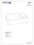
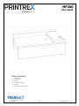
MP200
User Guide
Table of Contents
§
§
§
§
§
§
Preparation
Operation
Safety
Troubleshooting
Service
Technical Specifications
1028-0044-R9
1 of 10
www.transact-tech.com
MP200
Preparation
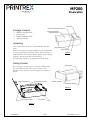
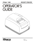
Front Panel
Paper Compartment Access Hole
Package Contents
§
§
§
§
Writing Surface/Paper
Compartment Door
MP200 Chart Recorder
Power Cord
Parallel Interface Cable
This User Guide
Unpacking
Locate and remove the Power Cord and Parallel Interface
Cable.
Paper Release Tab
Remove the protective end caps and plastic bag. The Recorder
can now be placed on the desired surface. Note that there is a
cardboard insert that holds the Writing Surface in place during
shipment. This insert should be removed now.
The packaging material is not required beyond this point.
Paper Exit Path
Figure-1
Getting Familiar
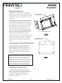
Power Switch
Review Figure 1 through Figure 3 to become familiar with
the names and locations of the various features of the
Recorder. These names are used throughout this Operators
Guide.
Paper Compartment
Paper Entry Channel
Interface Connector
Power Entry Module
Figure-2
Door in Open Position
Front Surface
Figure-3
1028-0044-R9
2 of 10
www.transact-tech.com
MP200
Preparation
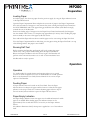
Setting the Paper Size
The Recorder is factory set for A-size (8 ½ by 11
inch) media. It is required to adjust the Recorder for
use with A4-size (210 by 297 mm) media. A Number
1 Phillips screwdriver is recommended to make the
adjustment.
The adjustment can be made by placing the Recorder
on its Front Surface (a cloth or towel can be used to
protect the Recorder and table top from scratches).
Locate and loosen (do NOT remove) the five Paper
Size Adjustment screws, see Figures 4 and 5. Slide
the Paper Adjustment Plate inward towards the
center of the Paper Compartment until it stops.
There are two holes in the Paper Adjustment Plate
that can be used to maneuver the Paper Adjustment
Plate into position. Tighten the adjustment screws
while holding the adjustment plate in position.
The Recorder can be reset to accommodate A-sized
media by using the above procedure except sliding
the Paper Adjustment Plate away from the Paper
Compartment then re-tightening the adjustment
screws.
Paper Size Adjustment
Screws (top, 3 ea.)
Paper Adjustment Plate
Figure-4
Paper Size Adjustment
Screws (bottom, 2 ea.)
Connecting the Parallel Interface Cable
Locate the Parallel Interface Cable and insert the
end that mates with the Recorder Interface
Connector (Figure-2). Insert the other end of the
Parallel Interface Cable to the Instrument Parallel
Port Connector (refer to the Instrument User
Guide/Service Manual to locate the Parallel Port
Connector).
Accessories equipment connected to the analog and digital
interfaces must be certified to the respective IEC standards (i.e.
IEC 950 for data processing equipment and IEC 601-1 for
medical equipment.) Furthermore all configurations shall
comply with the system standard IEC 601-1-1. Everybody who
connects additional equipment to the signal input part or signal
output part configures a medical system, and is therefore,
responsible that the system complies with the requirements of
the system standard IEC 601-1-1. If in doubt, consult the
technical services department or your local representative.
Figure-5
Connecting the Power Cord
Locate the Power Cord and insert the end that
mates with the Recorder Power Entry Module
(Figure-2). Plug the other end of the Power Cord to
the receptacle location described in the User
Guide/Service Manual of the Instrument the
Recorder is connected to.
1028-0044-R9
3 of 10
www.transact-tech.com
MP200
Preparation
Loading Paper
To load the paper, first clear any paper from the previous supply by using the Paper Advance button
or the Paper Release Tab.
Open the Paper Compartment Door and place the new stack of paper in the Paper Compartment.
Note: The orientation of the paper is such that the first sheet entering the Paper Entry Channel has
the NON-PRINTING side of the paper facing up AND the form marker (small black rectangle)
towards the rear of the Recorder.
Position the leading edge of the paper into the Paper Entry Channel and manually feed the paper
into the channel until it comes to a complete stop (approximately 3 inches). Note: Feeding the paper
with one hand, in the center of the paper yields best results.
Press and hold the Paper Advance button until the paper can be seen exiting the Paper Exit Path.
Close the Paper Compartment Door while being sure the paper exiting the Paper Exit Path is on top
of the Writing Surface. The paper is now loaded.
Running Self-Test
Before operating the Recorder, perform the self-test by turning the power
switch to the “On” position while holding down the Paper Feed Button.
Release the Paper Feed Button after the self-test begins. The Recorder will
perform various internal electronics tests as well as electromechanical tests.
The Recorder is ready to operate.
Operation
Operation
Use the Recorder for general charting and reporting. There are no special
controls or modes of operation to be set on the Recorder for normal operation.
Refer to the Instrument User Guide/Service Manual for the various output
options of the Recorder.
Feeding Paper
A Paper Advance button is located on the Front Panel. Press the Paper
Advance button to advance the paper until the button is released or the paper
advances to the Top of Form. To continue advancing paper after the Top of
Form is reached, release and then re-press the Paper Advance button.
Paper Empty Indication
The Paper Empty Indicator shows that paper is not loaded and remains lit while
paper is not loaded. When loading paper, the indicator remains on for
approximately four seconds after there is no activity on the Paper Advance
button.
The indicator illuminates briefly when power is applied as a test of the indicator
itself.
1028-0044-R9
4 of 10
www.transact-tech.com
MP200
Operation
Power Indication
The Power Indicator indicates that power is on and remains lit while power is
on.
Error Indication
The Error Indicator indicates an error condition with a series of long and short
flashes. The number of long flashes corresponds to the tens digit of the error
code and the number of short flashes corresponds to the ones digit of the error
code. The following is a list of error codes with their description:
11 – Paper Empty
21 – Under Voltage
22 – Over Voltage
23 – Under Temperature
24 – Over Temperature
43 – System Error
Refer to the trouble shooting section on page 7 for appropriate action in the
event of an error condition.
The Error Indicator illuminates briefly when power is first applied as a test of
the indicator itself.
Clearing a Paper Jam
In the event of a paper jam, lift the Paper Release Tab and gently pull the
remaining paper clear of the print head and platen. Do NOT use any sharp
objects or tools near the platen or print head or damage may result.
Care and Cleaning
There is no regular cleaning required for proper operation of the Recorder,
however the Recorder surfaces are designed and manufactured to permit
cleaning with the following cleaning agents:
Isopropyl alcohol
Ammonia
Chlorine bleach (1:10 concentration with water)
Hexachlorophene (PhisoHex)
Glutaradehyde (Cidex)
It is recommended that a soft cloth dampened with the cleaning agent be used
to clean the surfaces of the Recorder. Do NOT submerse or allow spills onto or
in the product.
1028-0044-R9
5 of 10
www.transact-tech.com
MP200
Safety
Restriction on Use
Use this equipment only for its intended use as described in this guide.
§ Do not use power supplied outside the specified voltage/hertz range.
§ Do not block any openings on the equipment.
§ Do not use corrosive chemicals or vapors on the equipment.
§ Do not expose equipment to rain spills or moisture.
Grounding
This equipment must be grounded. Connect only to a properly grounded outlet.
Power Cord
The power cord supplied with the equipment is a hospital grade power cord.
§ Do not operate the equipment if it has a damaged power cord or plug.
§ Do not immerse power cord or plug in water.
§ Do not use a power cord other than that supplied with the equipment.
Serviceability
There are no user-serviceable parts inside the equipment. Refer all service to a qualified service
technician.
FCC Compliance
This unit has been tested and found to comply with the limits for a Class A digital
device, pursuant to Part 15 of the FCC Rules. These limits are designed to provide
reasonable protection against harmful interference when the equipment is
operated in a commercial environment. This equipment generates, uses, and can
radiate radio frequency energy and, if not installed and used in accordance with
the instruction manual, may cause harmful interference to radio communications.
Operation of this equipment in a residential area is likely to cause harmful
interference in which case the user will be required to correct the interference at
his own expense.
Declaration of Conformity
TransAct Model: Printrex MODEL MP200-02 - MEDICAL CHART RECORDER is
declared to conform with the following standards.
RoHS Directive for IT and Telecommunications Equipment
The Printrex MP200-02 shall be compliant with "Directive 2011/65/EU of theEuropean
Parliament and of the Council of 8 June 2011 on the restriction of the use of certain
hazardous substances in electrical and electronic equipment" ("RoHS Directive")
1028-0044-R9
6 of 10
www.transact-tech.com
MP200
Troubleshooting
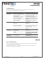
Troubleshooting
Your chart recorder is designed and manufactured to provide consistent and reliable service.
However, in the event of a problem, consult the chart below.
SYMPTOM
POSSIBLE CAUSE
WHAT TO DO
No power in unit
1. Power cord is not plugged into outlet.
1. Verify power cord is firmly plugged into outlet.
2. Power cord is not plugged into recorder
power entry module.
2. Verify power cord is securely connected to
the recorder Power Entry Module.
3. Power switch is in the OFF position.
3. Verify the switch is in the correct position.
4. Outlet is not providing power.
4. Plug another device into the outlet to check
for power.
5. Power cord is defective.
5. Plug another device onto power cord to
check for power.
1. Power switch is off.
1. Turn on power.
2. Paper is out.
2. Reload paper.
3. Paper is jammed.
3. Clear the paper jam.
4. Interface cable is unplugged.
4. Check that the interface cable is securely
attached at both ends.
5. Interface cable is defective.
5. Try the interface cable on another working
system.
1. Power switch is off.
1. Turn on power.
2. Paper is not inserted far enough into
recorder.
2. Gently hand feed paper into recorder Paper
Entry Channel until it stops firmly against the
platen (approximately 3 inches), then press
Paper Advance button.
1. Paper is mis-aligned.
1. Raise the Paper Release tab and align paper
parallel to recorder.
No recorder output
Cannot load paper
Paper skews and
causes a paper jam
Service
How to Obtain Service
Refer to the User Guide/Service Manual of the Instrument the Recorder is connected to for contact
information regarding servicing this Recorder.
The model and serial number of the Recorder is located on the rear of the unit. Please have this
information available when service is required.
1028-0044-R9
7 of 10
www.transact-tech.com
MP200
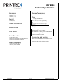
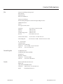
Technical Specifications
Dimensions
Storage Temperature
152mm (6”) H
406mm (16”) W
305mm (12”) D
-20°C (-4°F) to 75°C (167°F)
Fuse
3.0 Amp, 250V Slo-Blo
Weight
CAUTION: For continued protection against risk
of fire, replace only with same type and rating
fuse.
6.4kg (14lb)
Power Requirements
ATTENTION: Utiliser un fusible de rechange de
meme type.
100-240VAC, 50-60Hz
Usage
Data Interface
Class 1, No Applied Part Protection against
harmful ingress of water: ordinary
Not suitable for use in the presence of flammable
Anesthetics or oxygen
Continuous mode of operation
IEEE 1284 Parallel
Chart Speed
5, 25, 50, 100mm/sec
Chart Resolution
Accessories and Supplies
8 dots/mm (Y-axis)
20 dots/mm (X-axis) at 5, 25 and 50 mm/sec.
10 dots/mm (X-axis) at 100 mm/sec.
Please refer to the Instrument User Guide/Service
Manual for information on the available
accessories and supplies for this Recorder.
Media Compatibility
A Size (8 ½ by 11 inch)
A4 Size (210 by 297 mm)
1028-0044-R9
8 of 10
www.transact-tech.com
Contact Information
USA
TransAct Technologies Incorporated
Ithaca Facility
20 Bomax Drive
Ithaca, NY 14850 USA
TransAct Technologies
World Gaming Headquarters & Western Regional Repair Center
6700 Paradise Road
Suite D
Las Vegas, NV 89119 USA
Telephone
Main fax
Sales fax
Technical Support fax
Web site
(877) 7ithaca or (607) 257-8901
(607) 257-8922
(607) 257-3868
(607) 257-3911
www.transact-tech.com
Western United States
United Kingdom
877-822-8923 / Fax 702-254-7796
011-44-170-977-2500 / Fax 011-44-170-977-2505
R - Associates Inc.
6610 Gant Road
Houston, Texas 77066 USA
Telephone
713-973-1500 / Fax 713-598-8311
Web site
www.r-associates.com
United Kingdom
AVNET Embedded
5a Waltham Park, White Waltham
Maidenhead
Berkshire, SL63TN
Telephone +44 1628 518900
Web site
www.avnet-embedded.eu
Canada
Kesh Downhole Measurements, Inc.
PO Box 246
Clyde, Alberta T0G 0P0 Canada
Telephone
780-348-5278 / Fax 780-348-5731
Email
[email protected]
1028-0044-R9
9 of 10
www.transact-tech.com
Contact Information
Germany
Elkutec Electronic GmbH
Postfach 11 33
D-85386 Eching bei Munchen
Erfurter Strasse 31 Germany
Telephone (49)-89-31-90-91-0 / Fax (49)-89-31-90-91-91
Web site
www.elkutec.de
Email
[email protected]
China
Star-Luck Enterprises, Inc.
Beijing Office
Room 328, Grand Vision Business Building
No. 2 Jiuxianqiao Road
Chaoyang District
Beijing 100015 China
Telephone 86-10-51305677 / Fax 86-10-51305658
Singapore
HABS Industries Pte Ltd.
2 Kensington Park Drive
#04-04
Singapore 557320
Telephone
Email
1028-0044-R9
65-967 32002 or 65-816 32322 / Fax 65-234 3158
[email protected]
10 of 10
www.transact-tech.com