1
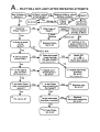
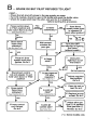
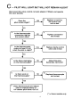
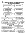
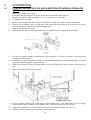
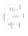
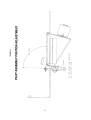
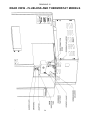
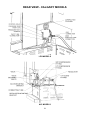
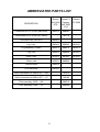
SERVICE
MANUAL
for
BOSTON (MG 3000 STD)
SANTA FE
(CALGARY, MG 3000 FLS)
& ODESSA (PG 3000)
GAS FIRES
TO BE USED ONLY BY AUTHORISED PERSONNEL
PART No 588402
Issue E — © Nov. 2001
CONTENTS
TROUBLESHOOTING
Page
A. Pilot will not light after repeated attempts ....................................................2
B. Spark OK, but pilot refuses to light..............................................................3
C. Pilot will light but will not remain alight .......................................................4
D. Pilot alight but burner will not light within ten seconds.................................5
E. Thermostat heaters. Pilot alight but burner will not light ...............................6
F. Thermostat heaters. Erratic operation ...........................................................7
ASSEMBLY AND DIS-ASSEMBLY
Removing the glass or glass assembly ................................................................8
Fitting the glass assembly, the louvre assembly, the dress
guard and the front panel ...............................................................................8, 9
Disconnecting the flue........................................................................................9
Removing and replacing the cabinet .............................................................9, 10
Access panels, removing and replacing.............................................................10
Replacing the control adaptor (early Calgary models).......................................10
Removing and replacing the pilot assembly ......................................................10
Removing and replacing the burner ..................................................................11
Accessing the main injector..............................................................................11
Accessing control valves and regulators ...........................................................11
Accessing the fan assembly ..............................................................................12
Removing and replacing the pedestal................................................................12
Removing and replacing the pedestal foot ........................................................12
SERVICE ADJUSTMENTS
Gas pressure adjustment ..................................................................................12
Checking the flue draught ................................................................................13
Calgary thermostat adjustment .........................................................................13
Converting from LPG to NG ...........................................................................14
Calgary valve conversion .................................................................................15
Remote control installation ........................................................................15, 16
DRAWINGS
No 1.
No 2.
No 3, 4.
No 5.
No 6.
No 7
No 8.
No 9.
No 10.
No 11.
No 12.
No 13.
No 14.
Electrode adjustment.........................................................................17
Spark gap .........................................................................................18
Pilot gas flow test .............................................................................19
Pilot jet check ...................................................................................20
Pilot assembly position adjustment ....................................................21
Pilot flame alignment for cross-lighting .............................................22
Log positioning.................................................................................23
Remote thermostat wiring test...........................................................24
Pilot assembly and adjustment ...........................................................24
Rear view (Standard models) ............................................................25
Rear view (Flueless and Thermostat models).....................................26
Rear view (Accessory models) ..........................................................27
Rear view (Calgary models) ..............................................................28
TABLES
No 1.
Gas pressures....................................................................................29
No 2.
Pilot jet sizes.....................................................................................29
No 3.
Main burner jet sizes .........................................................................29
Abbreviated Parts List .....................................................................................30
1
2
3
4
5
6
7
1. ASSEMBLY AND DIS-ASSEMBLY
1.1
REMOVING THE GLASS OR GLASS ASSEMBLY
In early models (with vertical corner tie-rods), the glass is mounted in an assembly which lifts out as a
complete unit. In later models the three panes of glass are removed one at a time.
1.1.1
1.
2.
3.
4.
1.1.2
1.
2.
3.
4.
5.
EARLY MODELS
Remove the front panel (below the glass assembly) by lifting up about 5mm and pulling it toward you.
Remove the dress guard (if fitted) by pulling it forward at the bottom and then lift it clear.
Remove the louvre assembly by lifting it up about 5mm and pulling it carefully toward you.
The glass assembly is held by five screws, three at the top and two at the bottom. First remove all but
the centre top screw, then, holding the glass assembly against the cabinet, finally remove the last
screw. Carefully lift the assembly clear of the cabinet.
LATER MODELS
If the dress guard is fitted, follow steps 1 & 2 in 1.1.1 above
Remove the louvre assembly by lifting it up about 5mm and pulling it carefully toward you.
Remove the six top glass trim fastening screws (four along the front and one at each side) as
illustrated.
Before lifting the top trim clear, provide support for the three glass pieces to prevent them from falling
and breaking. Adhesive tape will do this.
Lift the front glass clear first, followed by each side glass. As each side glass is removed, a spring, a
backing strip and a glass rope will be released from behind its rear vertical edge.
1.2 FITTING THE GLASS , THE LOUVRE ASSEMBLY, THE DRESS
GUARD AND THE FRONT PANEL.
1.2.1.1 GLASS ASSEMBLY (Early Models)
1.
2.
3.
Apply a little high temperature grease to the five retaining screws.
Hook the two lugs on the top rail of the glass assembly over the top rim of the firebox, taking care to
align the assembly with the screw holes in the firebox. While supporting the glass assembly firmly
against the firebox, fit the top centre screw but do not tighten it fully.
Fit the remaining four screws loosely, and when all are entered, tighten them.
8
1.2.1.2 GLASS ASSEMBLY (Later Models)
1.
2.
3.
4.
5.
6.
1.2.2
1.
2.
3.
1.2.3
1.
2.
3.
4.
1.2.4
1.
2.
3.
1.3
Clean all inside glass surfaces carefully.
To install the first side glass, fit the spring, the backing strip and the glass rope (in that order) into the
retaining slot and then the glass. Push it back against the spring until the front glass can be dropped
into its slot.
Strap the two glasses together with a piece of adhesive tape at their adjacent top corners to prevent
them from falling out while the second side glass is being fitted.
Fit the second side glass after installing the spring, backing strip and glass rope as before. Push the
glass back against the spring, swing it in behind the front glass and push it down into the bottom
retainer slot. Another strip of adhesive tape will ensure that it stays in place while the top is being
fitted.
Fit the top trim and replace the six fastening screws. Before tightening the screws, ensure that the
three glass pieces are seated snugly against the top glass tape to prevent any leakage. Do not overtighten the screws.
Remove the adhesive tape, clean the glass and re-fit the dress guard (if required) and louvre assembly.
LOUVRE ASSEMBLY
Fit the keyhole slot at each end of the louvre assembly over its retaining post.
Press downward gently to engage the posts.
Confirm correct engagement by pulling forward on the louvre assembly.
DRESS GUARD (IF REQUIRED)
The front panel must be removed for fitting and removing the dress guard.
Angling the guard forward at the top, fit the two lugs at the top of the guard over the nuts at each end
of the top of the glass assembly.
Swing the lower edge of the guard under the firebox.
The guard is retained in position by fitting the front panel. (See 1.2.4)
FRONT PANEL
Fit the keyhole slot at each end of the front panel over its retaining post.
Press downward gently to engage the posts.
Confirm correct engagement by pull gently forward on the front panel.
DISCONNECTING THE FLUE
1.
2.
3.
4.
5.
6.
7.
1.4
Shut off the gas supply at the valve behind the heater.
Remove the access panel on the rear of the cabinet.
Disconnect the gas line at the heater.
Lift the flue sleeve about 75mm and support it with a wooden block.
Slacken any flue clamp and lift the flue while moving the heater from beneath it.
Slide the heater away from the wall, supporting the flue and trim on a suitable spacer.
Keep the heater upright at all times to avoid displacing the logs.
REMOVING THE CABINET
1.
2.
3.
4.
5.
6.
7.
8.
9.
10.
11.
12.
Remove the front panel, the dress guard (if fitted), the louvre assembly and the glass or glass
assembly (in that order) as detailed in Section 1.1. & 1.2
Remove both access panels. See Section 1.6.
Disconnect the gas supply.
Disconnect the flue, where applicable. See Section 1.3.
Remove the control knob and Piezo, where applicable.
Dismantle the diverter from the rear of the cabinet.
Withdraw the screws holding the rear panel of the cabinet to the heat exchanger.
Extract all the screws under the bottom outer edge of the cabinet.
Remove the screws inside the front of the firebox which fix the firebox sides to the cabinet.
If necessary, drill out the rivets holding the thermostat bulb.
Remove the control rod, but not the sleeve (or universal joint if this is fitted).
The cabinet can now be lifted straight up. Take care not to lose the bush in the control panel.
9
1.5
REPLACING THE CABINET
1.
2.
3.
4.
5.
6.
7.
8.
9.
10.
Lower the cabinet carefully over the firebox until it reaches the baseplate.
Feed the control rod up through the heat shield and the control panel.
Attach the lower end of the rod to the sleeve (or universal) at the valve.
Fit the bush on the control rod.
Replace all the cabinet retaining screws, taking care not to over-tighten.
Re-fit the thermostat bulb as necessary.
Replace the diverter at the rear of the cabinet.
Re-fit the control knob.
Replace the glass or glass assembly, the louvre assembly, the dress guard (if fitted) and the front
panel. See Section 1.2.
Re-install the flue and gas supply and check for gas leaks.
1.6 ACCESS PANELS
1.6.1
REMOVING THE REAR ACCESS PANEL
1.
2.
1.6.2
1.
1.6.3
1.
2.
3.
1.6.4
1.
2.
3.
1.6.5
1.
2.
1.6.6
Remove four screws, three on the face and one underneath.
Lift the panel clear.
REPLACING THE REAR ACCESS PANEL
Offer the panel into position and re-fit the screws. Do not overtighten.
REMOVING THE SIDE ACCESS PANEL
Remove two screws below the panel.
Lift the panel gently upward, pulling the lower edge outward.
Lower the panel until it is clear of the pins.
REPLACING THE SIDE ACCESS PANEL
Fit the large holes in the panel over the pins in the cabinet side panel.
Pushing upward, swing the bottom of the panel in until it is flush with the cabinet.
Replace the two screws. Do not overtighten.
REMOVING THE PIEZO/FAN SWITCH ACCESS PANEL
Remove the screws securing the panel to the top rear of the cabinet.
Lift the panel clear.
REPLACING THE PIEZO/FAN SWITCH ACCESS PLATE
1.
Offer the panel into position and re-fit the screws. Do not overtighten.
1.
2.
3.
4.
5.
6.
7.
8.
9.
10.
Remove the rear and side access panels See Sections 1.6.1 and 1.6.3
Remove the ‘R’ clip or split pin at the lower end of the universal.
Withdraw the universal from the adaptor.
Remove the two screws holding the adaptor and lift it clear.
Fit the modified adaptor onto the key in the plastic bush on the top of the control.
Replace the two retaining screws.
Carefully fit the universal joint onto the adaptor.
Rotate the control knob to align the holes and fit the ‘R’ clip or split pin.
Verify that the control knob is in the correct position.
Re-fit the access panels. See Sections 1.6.2 and 1.6.4.
1.
2.
Disconnect the gas and power supplies.
Remove the front panel, dress guard (if fitted), louvre assembly and glass or glass assembly. See
Section 1.1 & 1.2.
Carefully remove the logs.
Remove the front metering plate (three screws) and lift the draught shield clear.
Disconnect the gas pipe at the bottom of the pilot assembly.
Disconnect the Piezo wire at the bottom of the electrode.
The pilot assembly can now be released from the front of the burner. If it is to be withdrawn
completely, remove the side access panel and undo the thermocouple connection to the control valve.
For correct adjustments and assembly see Drawing No 10.
1.7
REPLACING THE CONTROL ADAPTOR (Early Calgary models)
1.8
REMOVING AND REPLACING THE PILOT ASSEMBLY
3.
4.
5.
6.
7.
10
8.
1.9
Follow the above order in reverse to re-assemble the pilot assembly. Note that the front metering
plate should be pushed back against the burner before tightening the screws.
REMOVING AND REPLACING THE BURNER
1.
2.
3.
4.
5.
6.
Follow steps 1 - 7 in Section 1.8.
Remove the panel (or fan) from the rear of the pedestal.
Disconnect the gas pipe from the main injector and unscrew it.
Remove the rear metering plate (just behind the burner, inside the firebox).
Extract the four screws retaining the burner, and lift it clear.
Replace the burner by following the above steps in reverse order.
Points to note are:The front and rear metering plates must be pushed up against the burner before tightening
screws.
The position of the pilot assembly is critical. See Drawings No 6, 7.
The logs must be in their correct positions. See Drawing No 8.
The main jet is to be screwed in by hand only and backed out one turn before attaching
pipe.
Any gas connections disturbed must be leak tested.
their
the gas
1.10ACCESSING THE MAIN INJECTOR
1.
2.
3.
Remove the panel (or fan) from the rear of the pedestal.
Disconnect the gas pipe from the main injector and unscrew it.
Note, when replacing the jet, it is to be screwed in by hand only and backed out one turn before
attaching the gas pipe. Any gas connections disturbed must be leak tested.
1.11ACCESSING CONTROL VALVES AND REGULATORS
1.11.1 STANDARD MODELS
1.
2.
3.
4.
5.
6.
7.
8.
9.
1.11.2
1.
2.
3.
4.
5.
6.
7.
8.
1.11.3
1.
2.
3.
4.
5.
6.
7.
8.
9.
Turn off the gas supply.
Remove the access panels. See Section 1.6.1 and1.6.3.
Disconnect the gas pipe at the inlet to the regulator. See Drawing No 11.
Disconnect the pipe between the regulator and the control valve.
At the control valve, disconnect the pipes to the burner and the pilot.
Also disconnect the thermocouple connection to the control valve.
Disconnect the control rod.
After removing their mounting screws the pressure regulator and control valve can be lifted clear.
Reassemble in the reverse order, taking care to check for gas leaks.
FLUELESS AND THERMOSTAT MODELS
Turn off the gas supply.
Remove the access panels. See Section 1.6.1 and1.6.3.
Disconnect the gas pipe at the inlet to the control valve. See Drawing No 12.
At the control valve, disconnect the pipes to the burner and the pilot.
Also disconnect the thermocouple connection to the control valve.
Disconnect the control rod.
After removing the mounting screws the control valve can be lifted clear.
Reassemble in the reverse order, taking care to check for gas leaks.
ACCESSORY MODELS
Turn off the gas supply.
Remove the access panels. See Section 1.6.1 and1.6.3.
Disconnect the gas pipe at the inlet to the control valve. See Drawing No 13.
At the control valve, disconnect the pipes to the burner and the pilot.
Disconnect the thermocouple connection to the control valve.
Also disconnect the thermopile connection to the control valve.
Disconnect the control rods.
After removing the mounting screws the control valve can be lifted clear.
Reassemble in the reverse order, taking care to check for gas leaks.
11
1.12ACCESSING THE FAN ASSEMBLY
1.
2.
3.
4.
5.
6.
Un-plug the lead from the mains supply.
Pull off the fan speed control knob at pedestal level. (Early models)
Remove four screws at the rear of the pedestal.
Early models. Operating from the speed knob end, move the fan assembly away from you while
swinging the far end rearward until the assembly can be lifted clear.
Later models. Lift the fan assembly partly clear of the pedestal and disconnect the wiring loom at the
connector plug close to the fan box. Then lift the fan assembly clear of the heater.
Reverse the extraction procedure when re-assembling.
1.13REMOVING AND REPLACING THE PEDESTAL
1.
2.
3.
4.
5.
6.
7.
Remove the fan (see Section 1.12) or pedestal rear panel as applicable.
Remove the front panel, dress guard (if fitted), louvre assembly and glass or glass assembly. See
Section 1.1 & 1.2.
Remove the logs.
Disconnect the thermostat bulb if attached to the pedestal.
Remove the four screws retaining the pedestal to the baseplate.
Lift the firebox clear. Note: The heat shield below the baseplate will still be partially attached.
Reverse the removal sequence when re-assembling the pedestal.
1.14REMOVING AND REPLACING THE PEDESTAL FOOT
1.
2.
To remove the foot, carefully slide the foot and trim forward, keeping it in contact with the floor.
To replace the foot, make sure the decorative trim is correctly in place before sliding them back
around the pedestal. If the foot is raised from the floor during this operation, the pedestal finish may
be marked.
2.
SERVICE ADJUSTMENTS
2.1
GAS PRESSURE ADJUSTMENT
1.
2.
3.
4.
All pressure adjustments must be made while the heater is operating on the ‘HIGH’ setting.
MG 3000 STD NG and BOSTON NG.
This has a pressure regulator separate from its control valve. The regulator must be set to 1.0 kPa.
The pressure test point is on the side of the regulator and the adjusting screw is on the top. Slacken
the lock-nut and rotate the screw by hand, screwing down to increase the pressure. Tighten the lock
nut after adjusting. See Drawing No 11.
MG 3000 STD LP and BOSTON LP.
This model has no internal pressure regulator as it runs directly on the 2.71 kPa pressure delivered by
the gas bottle regulator.
MG 3000 THM (NG & LP ) and MG 3000 FLS (NG & LP).(BM control valve)
These have a pressure regulator built into the control valve. The pressure test point is adjacent to the
gas outlet, and the regulator screw is behind the plastic plug just below the word ‘MAX’. Adjust
with a flat bladed screw driver to 1.0 kPa for NG and up to the 2.71 kPa delivery pressure from the
LPG gas bottle regulator. See Drawing No 12.
MG 3000 ACC (NG & LP).
These also have a pressure regulator inside the control valve. There are two test points side by side
on top of the control valve – the outlet pressure test point is the one closer to the flame size control
knob. If adjustment is necessary, uncouple the control rod from the top of the flame size control
knob, extract the screw from down the centre of this knob and pull the knob off vertically. The
pressure is then set by rotating the knurled plastic wheel exposed by removing the knob. Once the
pressure is correct (1.0 kPa for NG or 2.71 kPa for LPG), care must be taken not to turn the plastic
wheel as the knob is re-fitted in its maximum anti-clockwise position. This position is defined by the
skirt of the knob contacting the adjacent metal up-stand. Rotate the knob clockwise and then fully
anti-clockwise while observing the pressure to verify that it is correct before replacing the retaining
screw and re-coupling the control rod.
12
5.
6.
2.2
CALGARY NG
These have a pressure regulator built into the control valve. The pressure test point is the top one on
the end of the control valve furthest from the gas inlet. Pressure adjustments are made with the small
slotted screw above and slightly to the right of the gas inlet on the control valve. Adjust to 0.9 kPa.
See Drawing No 14.
CALGARY LP
There is no pressure regulator in the control valve. The correct pressure of 2.71 kPa should be
delivered by the gas bottle regulator. The test point for checking this pressure is the uppermost one
on the end of the appliance valve furthest from the gas inlet.
CHECKING THE FLUE DRAUGHT
BOSTON MG 3000 and PG 3000. After the fire has been alight on ‘‘HIGH’ for five minutes, hold a smoking
taper or match at the exit of the draught hood (behind the heater) to verify that the flue is drawing correctly
and that flue gases are not spilling into the room.
2.3
CALGARY THERMOSTAT ADJUSTMENT (EUROSIT 630 VALVE)
1.
2.
3.
4.
5.
6.
7.
8.
9.
10.
11.
12.
In some installations, the thermostat may close down the fire before the room temperature has
reached the desired level, even when the thermostat control knob is set to its highest position. To
correct this, follow the procedure below. A Torx Tamperproof T-20 screwdriver will be needed.
Close the gas supply valve and remove the side and rear access panels (1.6.1, 1.6.2)
Disconnect from the control valve the following items: The thermocouple, the pilot gas pipe, the
main burner gas pipe and the gas supply pipe.
Withdraw the top hairpin clip of the control rod, undo the valve mounting bracket fastening screws
and lift the valve clear of the appliance.
Remove the white plastic adaptor from the top of the valve control knob and prise out the black
plastic plug in the centre of the control knob, using a sharp pointed implement.
Turn the knob to the OFF position as shown by the indicator arrow on top of the valve.
Using a Torx Tamperproof T-20 screwdriver, carefully remove the central knob retaining screw
WHILE MAINTAINING FIRM DOWNWARD PRESSURE AGAINST THE SPRING INSIDE
THE KNOB. When the screw and washer are clear, allow the spring to expand as the top of the
knob is lifted clear.
Without rotating the knob, lift the bottom section of the knob upwards until the gear on its base is
clear of the light-coloured gear with which it meshes.
Without rotating the bottom section of the knob, turn the light-coloured gear about one quarter of a
turn CLOCKWISE and lower the bottom section of the knob into mesh with it again. (This will raise
the thermostat cut-in point about 12˚C).
Re-fit the spring, the top of the control knob, the retaining screw and washer, the black plastic plug
and the top white plastic adaptor.
Re-install the valve, the control rod universal joint and all connections to the valve.
Open the gas supply to the heater and test fire in the usual way, checking for gas leaks.
Replace the side and rear access panels.
13
3
CONVERSION
3.1
CONVERTING MG 3000, PG 3000 & BOSTON STD MODELS FROM LPG
TO NG
1.
2.
3.
4.
5.
6.
7.
8.
Remove the pedestal rear panel.
Disconnect the main injector feed pipe at the injector and remove the injector.
Remove the glass or glass assembly (see 1.1) to gain access to the burner.
Carefully remove the logs.
Remove the draught plate from in front of the burner, noting its position for later replacement.
Remove two retaining screws at each end of the burner and tilt the burner up at the front to access
and remove the two M4 pilot assembly retaining nuts.
Remove and discard the burner.
Disassemble the pilot assembly and replace the jet with the new one supplied. Re-assemble.
9.
Fit the new burner supplied, attaching the pilot assembly to it before lowering it into place and
securing with four screws.
10. Install the two metering plates (in front of, and behind the burner) and the draught plate, re-fit the
logs and re-install the glass or glass retainer.
11. Inside the pedestal, fit the new main injector (seven 0.95mm holes) and re-connect the main feed
pipe.
12. Remove the side and rear access panels.
13. Fit the regulator and the pipe connecting it to the control valve. (See illustration). The NG supply
connection can now be made to the regulator inlet. Check all connections for gas leaks.
14. Adjust the regulator for a test point pressure of 1 kPa at maximum firing rate. (See 2.1)
15. Replace all access panels and test the fire in the usual way.
14
3.2
CALGARY VALVE CONVERSION (BM to EUROSIT 630)
1.
2.
Close the gas supply valve and remove the side and rear access panels (1.6.1, 1.6.2)
Disconnect from the control valve the following items: The thermocouple, the pilot gas pipe, the
main burner gas pipe and the gas supply pipe.
3. Withdraw the top hairpin clip of the control rod, undo the valve mounting bracket fastening screws
and lift the valve clear of the appliance.
4. Disconnect the pilot gas pipe at the pilot assembly, and the main burner gas pipe at the main injector
elbow. Discard the pipes.
5. Remove the old control rod by lifting it up through the control panel at the top of the heater. Discard
the control rod.
6. Feed the new control rod and valve assembly up from the valve access area, passing the rod through
the holes in the heat shields and control panel. Bolt the valve in place, noting that the gas inlet is
facing to the rear of the unit. Fit the control knob on the top of the control rod.
7. Install the new pilot gas pipe and main burner gas pipe. When attaching the pilot gas pipe to the pilot
assembly, smear ROCOL MOLYCOTE J166 on the thread of the securing nut.
8. Connect the thermocouple to the valve.
9. Connect the gas supply pipe (and regulator, where required) to the valve and open the gas supply
valve.
10. Test fire in the usual way, checking for gas leaks.
11. Replace the side and rear access panels.
4
REMOTE CONTROL INSTALLATION
1.
2.
3.
4.
5.
Remove the side and rear access panels to gain access to the control valve.
Locate the short white jumper wire on top of the control valve at the gas outlet end.
Pull the jumper wire off both spade terminals and discard it.
The receiver unit supplied has four connecting wires attached to it. Only the red and white wires will
be used. Ignore the other wires.
Connect the red and white wires to the spade terminals originally occupied by the jumper wire, using
the terminal nearest you for the red wire and the one furthest away for the white wire. (See diagram).
15
6.
7.
8.
9.
EARLY MODELS. The receiver unit can now be mounted inside the rear access panel with the
screws supplied. (See diagram). Note. If response to the remote control is not sufficiently sensitive,
the receiver may be mounted outside the heater on the wall, facing into the room.
LATER MODELS. The receiver is mounted in a box which attaches at either rear corner of the
pedestal. Choose the side which gives best ‘coverage’ of the room.
Fit a battery (9 volt, size No 522 — not supplied) to the receiver and refit the access panel.
Install a battery (9 volt, size No 522 — not supplied) in the remote control and test run the
installation, following the instructions supplied with the remote control..
16
17
18
19
20
21
22
23
24
DRAWING 11
REAR VIEW - STANDARD MODELS
25
DRAWING 12
REAR VIEW - FLUELESS AND THERMOSTAT MODELS
26
DRAWING 13
REAR VIEW - ACCESSORY MODELS
27
DRAWING 14
REAR VIEW - CALGARY MODELS
LPG MODELS
NG MODELS
28
Table No 1 — Gas Pressures
Model §
High Fire
Gas Type
Low Fire
MG 3000 STD NG
Natural Gas
1.0 kPa
—
MG 3000 THM NG
Natural Gas
1.0 kPa
0.5 kPa
MG 3000 ACC NG
Natural Gas
1.0 kPa
—
MG 3000 FLS NG
Natural Gas
0.9kPa
0.5 kPa
MG 3000 STD LP
Liquid Propane Gas
2.71 kPa
—
MG 3000 THM LP Liquid Propane Gas
2.71 kPa
1.4 kPa
MG 3000 ACC LP Liquid Propane Gas
2.71 kPa
—
Liquid Propane Gas
2.71 kPa
1.4 kPa
MG 3000 FLS LP
§ Note: Gas pressures for PG 3000 models are the same as those for the
corresponding MG 3000 models.
Table No 2 — Pilot Jet Sizes
Gas Type
Nat. Gas
L.P.G.
Flue Fitted?
Pilot Jet Size
Yes
0.50 mm
No
Oxygen Depletion Sensor
Yes
0.30 mm
No
Oxygen Depletion Sensor
Table No 3 — Main Burner Jet Sizes
Gas Type
Nat. Gas
L.P.G.
Flue Fitted?
Main Burner Jet Size
Yes
7 @ 0.95 mm
No
7 @ 0.90 mm
Yes
1.5 mm
No
1.4 mm
29
ABBREVIATED PARTS LIST
DESCRIPTION
Boston
MG 3000
STD
Santa Fe
Calgary
MG 3000
FLS
Conversion Kit, LP to NG (BM valve)
988378
988381
Conversion Kit LP to NG (SIT valve)
Odessa
PG 3000
791170
Conversion Kit, NG to LP
988362
Log, front
988343
988343
988343
Log assembly, middle
988373
988373
988373
Log, rear
988056
988056
988056
Glass, front
991041
991041
991041
Glass, side
988002
988002
Thermocouple
588259
Pilot electrode
588166
Valve conversion kit, BM to SIT — NG
791073
Valve conversion kit, BM to SIT — LP
790182
Pilot assembly, ODS — NG
588310
Pilot assembly, ODS — LP
988309
30
Masport Gas Fires are manufactured in New Zealand by
MASPORT LTD. 1–37 MT WELLINGTON HIGHWAY.
P.O. Box 14-349 Panmure, Auckland 6 New Zealand.
Phone 09 570 9009, Free Fax 050 8570 570
For Technical Support: Phone (09) 570 8253 or (09) 570 8258