1
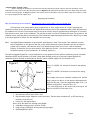
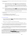
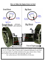
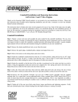
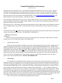
Camshaft Installation Instructions (Updated Sept 2015) We appreciate your choosing one of our real Chrysler® camshafts and installation kits for your engine. We have developed the following instructions to help everyone, from the first timer to the experts, install our camshafts correctly. For many engine builders this may be the most difficult job to do correctly. However for the best tech help in the industry we are only a phone call (309)745-9558, or email [email protected] , away. When the phone rings a human will answer. Shop hours 8-5 M-F C.S.T... Note: We supply coordinated parts such as lifters, springs, Break-In lubes, oils, etc. and we strongly recommend you use them to make sure you have successful results. Beware, there are many sub-standard parts available that have high rates of failure, we do not sell them. The actual cam, lifter, valve spring, and timing chain replacement is fairly straight forward and a standard automotive service manual procedure can be used….but as you know “the devil is in the details” and that is what we are going to explain. Intermediate shaft note: All Hughes Engines big block roller cams and the small block mechanical roller cams only, will require a coated steel distributor gear. Use SB #69970-1, BB #66970-1 HERE ARE THE DETAILS Preparation: There are certain tools you must have to do this job properly and some that make it easier and more accurate. We will call out the tools and parts numbers where appropriate. Cleaning and lubrication: Double check that the number stamped into the end of the cam matches what you ordered. Lightly wash the camshaft in clean solvent and blow it dry with compressed air. DO NOT BRUSH OR SCRUB A FLAT TAPPET CAM WITH ANYTHING!! With flat tappet camshafts, apply the supplied camshaft break-in lube to the cam lobes including fuel pump lobe, and the lifter bottoms only. NOTE: Roller cams do not require break in lube on the cam. Use light engine oil on the sides of the lifters. Use engine oil or assembly lube on the bearing journals, distributor gear, and pushrod ends. With roller tappet camshafts use a good quality heavy-duty engine oil to lubricate the camshaft and lifters. OIL- Oils have changed and not for the better, please use oil specifically designed for your cam type to protect cam, lifters, and pocket books. THIS IS VERY IMPORTANT!! Valve springs: Our camshafts are designed differently and have more lift than other cams of the same size; therefore it is mandatory that you use a spring with the correct amount of open (over the nose) and closed (seat) pressure and also check the valve spring installed height. The enclosed camshaft card will tell you our part number for the springs and the pressures/installed height to use. A minimum of .060” spring travel beyond the maximum lift is required. If you have a problem, we have many different retainers to adjust the installed height --- CALL US. When checking true double springs on a tester, be sure to use a retainer or other spacer to simulate the step on the head and/or retainer for the inner spring to duplicate the as installed configuration. If you are using a double spring assembly, we require you break in the camshaft with the outer springs only*. In this case assemble the heads with the outer springs only and follow the regular break-in instructions. After break-in add the inner spring assembly and go racing. Be sure and check the retainer-to-seal clearance. There should be a minimum of .060” of clearance at maximum valve lift. See oil section for further details on spring pressures and break-in. Page 1 Piston-to-valve clearance: Chryslers do not have the piston-to-valve clearance problems that many other engines experience. However, after the valve lifts exceeds .500” and above you must check to be sure. The critical area is not at TDC (top dead center). The critical areas are approximately 10 to 15 before TDC on the exhaust lobe and 10 to 15 after TDC on the intake lobe. We suggest a minimum piston-to-valve clearance of .060” intake and .110” exhaust. In the event you need additional clearance, we have a piston-notching fixture that we rent to our customers. It can be used on a short block in a car. Call for details. Part number’s Hug 8340 (small block) & 8342 (big block). Check lifter bores: The lifters must slide up and down and turn freely in the bore when lubricated only with WD-40 or similar light oil as a lubricant. You must be able to lift the lifter off of the cam, release it and hear it “thunk” against the cam. If it doesn’t do this, using only its own weight, it is too tight. If the old lifters had to be forced through the bore to remove them, it is quite likely that the lifter bore is damaged and will not allow the lifter to rotate properly. It doesn’t take much. Fix it or expect problems. Use our Lifter Broaching Tool, P/N 8319, to correct tight or damaged lifter bores. Lifters (Tappets): All flat tappet camshafts (both hydraulic and solid) must be installed with new lifters. NO EXCEPTIONS!!! Only roller camshafts can be installed with good used roller lifters. Flat tappet hydraulic & solid lifter clearance & rotation check It is mandatory that all flat tappet lifters be free in their bores and spin as the cam rotates in the block. We suggest the following procedure to test for both of these conditions, before final installation of the cam. 1) Install the camshaft clean and dry in the block, with oil only on the bearing journals. 2) Install your new lifters with dry bottoms and only a light coat of WD- 40® or similar light oil on the sides only. Never use used lifters. 3) Mark all the lifters and block with witness marks with a felt tip pen so you can see how far the lifters rotate. 4) Install the camshaft sprocket, only. 5) Using a speed handle and the proper socket, rotate the cam while applying a small pressure on the socket, to keep it properly located against the block. 6) Observe the lifters; they must rise and fall by their own weight. If not, they are too tight. We have a special tool to properly size and clearance the lifter bores, P/N 8319. 7) Rotate the camshaft at the speed of approximately 2 turns per second, for a total of 16 revolutions. Page 2 8) Check the mark on top of the lifter. It must indicate that the lifters were trying to rotate. You would like to see about 90º rotation indicated, though some may turn as much as 1 full turn. All lifters will not rotate the same amount or the same direction. If a lifter does not rotate at all - try again – the cam and lifter must be dry where they contact for this test to work properly. It may be necessary to move lifter(s) to other bores in order to see rotation. 9) If you encounter a lifter that absolutely will not rotate after following these steps contact us. 10) Make sure to install the lifters in the same bore during final assembly. DO NOT fill, pump-up, or soak any hydraulic lifters before installation. Mechanical camshafts should be given slightly less valve lash for break-in only, with iron heads approximately .004”/.005” less. This causes the lifter to spin more easily. When using aluminum heads the cold lash setting for mechanical cams should be about .006/.004” tighter than called for Hot, during initial start-up and break-in. Be sure and check pre-load/lash when the lifter is on the heel of the camshaft. If you do not have adjustable rocker arms or pushrods and you find the preload is incorrect, you may need either rocker shaft shims, longer or adjustable pushrods. Hughes Engines Inc. can supply all these parts if needed, call us. Installing and Adjusting Hughes Hydraulic Lifters 1. Do not wash in any solvent. Wipe the parts off with a lint free towel. 2. Use 10W30 oil and lube the O.D. of the body as well as wheel on roller lifters. 3. The desired lifter-to-bore clearance on cast iron blocks is: .0015” - .0017”. On aluminum blocks that oil the lifter, the clearance is: .0012” - .0014”. Both of these measurements are at 70 Deg F. Aluminum blocks will have a higher rate of expansion and that is why the clearance is tighter. Adjusting the pre-load setting of the Lifter Select the pre-load needed from the list below. Lifter part numbers 5001, 5003, 5006 & 5007 Cast iron block & cast iron heads: .080-.085” Cast iron block & aluminum heads: .090-.095” Lifter part numbers 5319 & 5321 Cast iron block & cast iron heads: .020-.025” Cast iron block & aluminum heads: .030”-.035” Aluminum block & aluminum heads: .045”-.050” 1. Use the firing order to set the valves. Mopar V8 firing order: 1-8-4-3-6-5-7-2 2. Put #1 cylinder on top dead center. 3. This puts the int. and exh. to be adjusted on the base circle of the camshaft. 4. Place a feeler gage blade, chosen from the list above, between the valve tip and the rocker arm. 5. Tighten the adjusting screw, or nut, until you can no longer spin the pushrod by rubbing your finger across it. This is zero ("0") lash. 6. Withdraw the feeler gage and note how far you must continue to turn the adjuster screw to reach zero ("0") lash. Now continue to tighten the adjuster screw that same amount to preload the lifter. 7. Repeat these adjustments for each cylinder running through the firing order. Note: High performance hydraulic cams/lifters are not as quiet as stock cam. Page 3 Magnum (Roller Hydraulic Cams) Before removing the distributor, mark the base and the intake with “witness” marks so that the distributor can be reinstalled correctly. Keep in mind that the distributors in Magnum truck applications DO NOT control the spark timing and cannot be “timed” with timing light. All Magnum hydraulic roller lifters need 2 turns (.080”) of pre-load. Roller cams do not require a breakin or spring changes like flat tappet cams. Degreeing the camshaft Why you should degree the camshaft? We want this cam to run the best it can, you should too!! You’ve spent a lot of money and are going to spend a lot of time—might as well do it right. Degreeing the camshaft correctly with a dial indicator and degree wheel tells you that all the components that control the position of the camshaft are accurate. Just because many of the parts are new, does not guarantee they will degree-in accurately with the other parts, such as the crankshaft. The only way to know is to check. Checking the center-line position of the camshaft can be confusing due to the similarity of the terms lobe separation angle and center-line. We will try to make it as easy as possible to center-line the camshaft the correct way. Note: All Hughes Engines camshafts are ground with some advance in them. This means if the camshaft is centerlined or degreed-in to the specs on the cam card it will be advanced to match whatever the cam card says is ground into it. However, this does not mean if you install the sprockets “dot-to-dot” it will be advanced properly. It should be, but you don’t know for sure unless you check it. (You do not need to enter the degrees of advance into any of your calculations. It is already figured in.) The lobes on Hughes Engines Inc. are non-symmetrical. A non-symmetrical lobe will have a different center-line when checked at 0.050” above the base circle than it does when checked at the top of the lobe. Hughes Engines Inc. camshafts must be checked at the bottom of the lobe, which is 0.050” tappet lift off the base circle. Figure 1 Point B Rotation "X" Point A Base Circle Point “A” is 0.050” off the base circle and is the opening point. Point “B” is 0.050” off the base circle and is the closing point. For example, let’s say our camshaft is advanced 4 and will have a center-line that is 4 less than the lobe separation angle. In this case, if the lobe separation angle is 111, a 4 advance would be 107 centerline (111-4) “X” is the difference of the center-line at the top of the lobe vs. at 0.050” off the base circle. Tools required or that make the job a lot easier 1. Dial indicator with at least .500” travel 2. Degree wheel (Larger diameter is more accurate). The best ones are marked 0º to 90º and then go backward from 90º to 0º. 3. Pointer for the degree wheel Note: All of the above are included in kit #8346 4. Crankshaft turning tool p/n 4799 or 67493 5. Height mike p/n 8338 for setting valve spring heights 6. Burnishing Ball p/n 8319 Page 4 Locating Top Dead Center (Note: Finding true top dead center is the area where many mistakes are made. Follow these instructions carefully.) In this example we will work with the intake lobe on cylinder #1. 1. Install your “real Chrysler” camshaft, “Pro-Gear” timing chain and gears. For checking purposes only, set the 2. sprockets “dot-to-dot”. Do not re-use the old chain and sprockets. Start by rotating the crankshaft 360 to position the piston in cylinder #1 back at the top of the cylinder. Then mount the degree wheel to the front of the crankshaft with the 0 (zero) or TDC mark at the 12 o’clock position. Mount the pointer to the block and position it to point to the TDC (zero) mark on the degree wheel. 3. Next, mount the dial indicator on the top of the block with the plunger contacting the center of the piston and about .100” preload. 4. Rotate the crankshaft clockwise and counter-clockwise past TDC. Then zero the dial indicator at the highest point of the piston travel. This is not true TDC, yet! Again, rotate the crankshaft clockwise until the piston has descended exactly .060” below TDC as shown on the dial indicator. Mark this position on the degree wheel (masking tape and a pen works well). Precision is important at this point. Your mark should be approximately 3º to 10º from TDC. We will call this point “A”. 5. Back up the crankshaft, (turning it counter-clockwise) moving the piston up to the top position and then down in the bore. Allow the piston to go about .100” down and then stop. Now rotate the crankshaft clockwise until the dial indicator shows exactly .060” before the piston has reached TDC. At this position, mark the point on the degree wheel “B”. Exactly ½ way between points “A” and “B” is true TDC. 6. Rotate the crankshaft clockwise until the pointer is at the exact ½ way point between “A” and “B”. This point may or may not be on the zero mark of the degree wheel, but very close if you have followed these instructions properly. Now the crank and piston position are at true Top Dead Center. Reposition your pointer to the zero mark on the degree wheel, and you are ready to proceed. Checking the Open and Closing Points of the Intake Lobe 1. Install a lifter on the intake lobe corresponding to the piston you just checked TDC (#1). Lubricate the bottom of the lifter with very light oil, such as WD-40 (do not use cam lube or oil at this time) and check to make sure it moves freely in its bore. The weight of the lifter and the dial indicator spring are the only things pushing the lifter down against the camshaft. If the lifter hangs or binds in the lifter bore even slightly during checking, you will get very confusing results and the job will be difficult. 2. Turn the crankshaft clockwise until the lifter is on the heel (base circle) of the camshaft (See Figure 1). At this point zero the dial indicator with about .100” preload on the push rod cup in the lifter. The indicator plunger must be inline with the lifter’s line of travel. 3. Rotate the crankshaft clockwise until the lifter has lifted .050” according to the dial indicator, this will be Point A in Figure 1. Note the position of pointer on the degree wheel. Masking tape and pen, accuracy important here. 4. Continue to rotate the crankshaft and the lifter will rise to over .300” lift and then begin to descend. When the lifter descends, equal to what it rose, which will be a point .050” before reaching point “B” the base circle, stop. Make a note of the location of the pointer on your degree wheel; this is the intake closing point. Always turn the crankshaft clockwise while checking the camshaft timing, NEVER back up! Page 5 5. Half way between Point A and Point B is the camshaft centerline and should correspond to the centerline printed on the camshaft card. Example 1: When using a small cam where the intake opens after TDC with a 112 lobe separation angle. If for example the intake should open at 2 ATC (After Top Center) and close at 36 ABC (After Bottom Center). Add up the total number of degrees from 2 ATC to BDC (178) and the number of degrees from BDC to 36 ABC (36), 178+36 = 214. Divide 214 by 2, this is 107. The 107 is added to the opening point of the 2 ATC equaling 109, which is the proper intake centerline and 3 advanced for the sample cam. Example 2: Using a larger camshaft where the intake opens before TDC with a 107 lobe separation angle. If for example the intake should open at 21 BTC (Before Top Center) and close at 49 ABC. Add the 21 BTC and the 180 (from TDC to BDC) and the 49 ABC, which totals 250. Divide the 250 by 2, this is 125. Starting at 21 BTC (the intake opening point) the centerline of the lobe is 125 after the intake opens which puts the intake centerline at 104 ATC, just as the camshaft card reads. 6. The following are general guidelines for comparing your measured points vs. the numbers on your cam card. If the centerline is within: a. 1º of the camshaft spec card, then put then engine together b. 2º of the camshaft spec card, correct it as necessary. c. If you have to choose between 1º advanced or 1º retarded, pick 1º advance. Corrections and Final assembly 1. Correct the timing as necessary and Recheck. Crankshaft sprockets with 3 keyways, offset keys and offset bushings are notoriously inaccurate. We have found the Pro Gear® timing chain assembly to be very accurate and long-lived, which is why we use and sell them. 2. When it’s correct, Loc-Tite® the bolts, torque to spec and put it together. Tips: This method is for Hughes Engines’ “real Chrysler Cams” and may not work with other brands of cams. If the engine is on an engine stand, rotate it so the lifter is vertical which helps it follow the lobe more accurately. In our shop we use an “extra-long” lifter (7”) to add weight to help the lifter follow the cam lobe and to allow us to position the dial indicator in a more readable position. The extra-long lifter is 3 old lifters tack welded together. The process of degreeing a camshaft can require removing and reinstalling the degree wheel several times, re-setting the degree wheel each time is VERY time consuming. This time can be greatly reduced by using our tool p/n 4799 crankshaft turning tool. You need to find T.D.C. once on each job. Using cam break-in lube or oil between the cam and lifter during the degree-in procedure can cause errors, due to hydroplaning. A common problem encountered when installing a timing chain and sprockets is to install the ignition distributor 180º out of time. This happens because the piston is on the overlap stroke, not the compression stroke. This is why. When the sprockets are in the classic installation position, with the cam sprocket’s dot down at 6:00 position and the crank sprocket’s dot up at the 12:00 and the number 1 piston at top dead center, it is not on the compression stroke. Rotate the crank 1 more turn, putting both sprockets’ dots at 12:00 and the #1 piston at top dead center. Now you are on the compression stroke, and you can install the distributor. (No, I don’t know why it is this way. It has been this way forever, on all American engines since timing chains have been used). It’s probably Al Gores idea; he has lots of good ones! We suggest that you spray the timing chain libercy with gel lube before installing the timing cover. Page 6 How to Make the Engine Easier to Start With the engine on the compression stroke on #1 cylinder, set the crankshaft to 10º or 12º before TDC as shown above. Install the distributor so the rotor has just passed the #1 cylinder terminal on the cap as shown above. Make sure you have fuel in the carb, lines and tank. Fire it up! Rev softly between 1500-3000 RPM for 30 minutes. Start-Up: It is very important that the engine does not turn over more than 3 or 4 times to fire up. While you are cranking over the engine, the break-in lube is being wiped off---BAD NEWS!!! Do not crank the engine with a new cam to: 1. 2. 3. Bring up the oil pressure.---- Use an oil pump primer shaft Fill the carburetor with fuel. ---- Use your electric pump or take the line off and fill it by hand Check the spark. ---- Take the distributor out and spin it by hand with the ignition key on (non—Magnum) Don’t listen to anyone who says to do this differently, you don’t want a flat cam and we don’t want to hear about a flat cam. People who tell you differently are not your friends. Triple check the ignition timing see the diagram on page_7_ (approximately 10º to 12º BTDC is good) and spark plug wire order before touching the key. Most start-up problems occur here. Pump the carburetor (4 or 5 times) to squirt fuel into the manifold. Make sure your battery is up to full charge and that you have sufficient fuel to run 30 minutes. The carburetor idle screw should be turned approximately ½ to ¾ turn to make sure the engine idles properly. DO NOT Let the Engine Idle under 2000 RPM the engine for the first 30 minutes. If you have an oil or water leak that is not dangerous continue to run the engine 10 minutes before you shut it off. Now you are ready: Fire it up! The engine should not idle in the first 30 minutes. Rev the engine gently from 1500 to 2500 RPM max. After the break in period, reset the idle and timing. Check for air leaks (vacuum), fuel leaks, oil leaks, and coolant leaks. Correct as needed. Install the inner valve springs if they were removed and check the valve lash. During the break-in period the combustion chambers are very hot and the headers may appear to glow. This is normal and should go away after break-in when the engine returns to normal idle speeds. Gently revving the engine during break-in will eliminate or greatly reduce these conditions. If you do not follow these instructions, you may be very sad!! The most important time in the life of your new camshaft and lifters are the first few minutes of start-up. If you have any questions, CALL US BEFORE YOU DO IT! There are no dumb questions. After you make the mistake, they are dumb questions because you already know the answer. The odds are in your favor, only about 1 in 400 people screw-up and flatten their cam. If you have any questions about the components recommended for your camshaft refer to the supplied cam spec card or call us. Diagnosis: Hydraulic lifters that lose their prime (collapse) quickly after start up, have dirt in them. The lifters with dirt in them can be disassembled and cleaned or replaced. Many problems are created during disassembly of an engine prior to a rebuild by pulling damaged lifters up through the lifter bore causing grooves and burrs in the bore. These burrs will make lifter spin difficult, if not impossible. If you flatten a lobe, checking the sides of the lifter with a 10X magnifying glass will show the grooves about 1/8” to ½” off the bottom of the lifter on the sides. Sometimes they will be deep enough to feel with your fingernail. These grooves act as a keyway and prevent lifter rotation causing cam and lifter damage. A dry or improperly lubricated camshaft will suffer damage as soon as the engine is fired up. The lobe and lifter can be totally destroyed in a few seconds. The engine should run for 16-20 hours before the lobe wear pattern is completely across the tip and the swirl grind marks on the bottom of the lifter are gone. Quicker developing wear patterns indicate problems such as spring stack up, wrong oil, or too much break-in pressure. Flooding the crankcase with fuel is a leading cause of cam/lifter failure. Excessive fuel pressure sticking float, etc. causes the oil to list its’ lubrication ability. Say “goodbye camshaft.” With Holley type carbs, we suggest a 3.5 power valve for break-in. Coolant leaks can also destroy the oil’s ability to do its job. Page 8 Camshaft Lubrication Facts -----------OIL ----------DO NOT USE ANY OIL THAT HAS API RATINGS/LABELS ON THEM WITH ANY FLAT TAPPET CAMS. These oils have either too little zinc-phosphate additive and/or too much detergent to properly lubricate any flat tappet cam and lifters. They are designed this way due to government regulations to prevent damage to Algore’s precious catalytic converter. We couldn’t care less about Algore but we do care about you and your camshaft. ------Details-----Zinc-phosphate (ZDDP) additive is our best friend in oil, especially in break-in oil. ZDDP clings to hot high friction areas of an engine, specifically cam lobes and lifters. They prevent metal-to-metal contact with a sacrificial coating on those areas. You need a minimum of 1200 parts per million (PPM) of ZDDP after the cam is broken-in. During break-in you should use oil with 2200/2400 PPM. This amount is no longer available in A.P.I. rated oils. These are the generally available oils, and the ZDDP was reduced (by law) to less than 1000 PPM in 1996 and less than 850 PPM in 2001, so you can see how bad it is. Now to make things even worse, detergent, which is also in all oil in varying amounts, competes with the ZDDP for position on the cam and lifters. The more detergent, the less effective the ZDDP is. Some oils have sufficient ZDDP but they also have so much detergent in them as well, that the ZDDP can’t do the job that you think it should, based on the amount of ZDDP they list. That is why modern oils aren’t suitable for street rod or performance engines with flat tappet cams*. These facts apply to all diesel and synthetic oils too! Additives: ZDDP is a family of additives and can react to other oils and additives in non-beneficial ways when poured in separately. You must be a petroleum chemist to know what will work. You may think that pouring in a bottle of a ZDDP additive is a cheap way around the problem—it’s not. All flat tappet cams now require specialty oil. We use and suggest these fine oils. For Break-In Joe Gibbs Driven BR 10W30 Joe Gibbs Driven BR 5W30 The above break-In oils are non-synthetic and suitable for breaking-in fresh rings. After Break-In Joe Gibbs Hot Rod 10W30 Conventional Joe Gibbs Hot Rod 10W30 Synthetic† Joe Gibbs XP3 10W30 Synthetic †We recommend synthetic oil only after cam and ring break-in. Page 9 Note: Our soluble-moly Extreme Pressure Lubricant part number 3690 is still a suitable additive for hydraulic flat tappet cams with 320# lbs open pressure or less and API oils with an API rating of SJ or SL. *As an example of detergent-to-ZDDP ratios, API rated oils may have 4 parts detergents to 1 part ZDDP ratio where Joe Gibbs Driven Break-In is about 1 part detergent to 6 parts ZDDP, over 20 times better! For further information on oil please refer to our Tech Articles on our website. Engine Oils--Article #203 . (309)745-9558 or email [email protected] Page 10