1
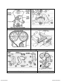
TRU-TIME
CAM
GEARS
1993 – 1997 Dodge Neon
Part number 23 – 850 series
,!
WARNING:
This installation is not for the mechanically challenged! If you
are not mechanically inclined or do not understand the
procedure please do not attempt the installation. Refer the
installation to a reputable mechanic. It is highly recommended to
purchase the factory service manual to use as a guide along with
these instruction sheets.
Legal in California ONLY for racing vehicles, which may never be used upon a highway.
You have just purchased the BEST adjustable cam sprockets available. These AEM
Inc. adjustable cam sprockets are CNC machined from billet aluminum and then laser
etched with cam timing marks for adjustment up to ±10° at the cam or ±20° at the
crankshaft. Using the vernier scale on the sprocket hub helps to perform cam timing
changes quickly and accurately. The inner hub is anodized for lasting beauty and
resistance to corrosion. The out gear sector is hard anodized for resistance to wear.
We have found that there are significant power gains to be made by adjusting the cam
timing even with stock cams and compression. Adjustable cam sprockets are usually
required in applications where an aftermarket or reground performance cams are
installed or the cylinder head has been milled 0.005” or more. The use of these cam
sprockets allows the extraction of maximum power from your engine. We have recorded
gains of up to 10~15 horsepower due to cam timing tuning using adjustable cam
sprockets.
When aftermarket or reground cams are installed, the original manufacturer’s cam
timing specifications are no longer accurate. These adjustable cam sprockets allow you
to make necessary adjustments to cam timing to maximize the performance of your
engine. This is accomplished by “degreeing in” the optimum cam timing for a particular
engine set up.
The adjustable cam sprocket is especially effective when used with heads that have
been milled. The adjustability of the sprocket allows the accommodation of the changes
in cam timing due to the variation of timing belt length from the bottom sprocket to the
top sprocket when the head is milled. If the head has been milled 0.005” or greater the
relationship between the head and the block is altered by moving the head closer to the
crankshaft resulting in retarded cam timing.
It must be emphasized that the preceding descriptions are generalizations and any
adjustments made must be done with a conservative approach and on a dynamometer
or on a racetrack. We do not condone any illegal activity on the street.
Read and understand these instructions BEFORE attempting to install this
product.
1) It is important that the installer familiarize themselves
with the procedures before starting the installation. This
procedure requires some very specialized tools, which
cannot be substituted with any substandard equipment.
It is important to have a factory service manual
available for reference while undertaking this
installation. This procedure is best accomplished using
a lift. If a suitable lift is not available, for safety reasons,
use appropriately rated jackstands.
2) Disconnect the negative battery cable.
3) With the front of the vehicle raised, drain the coolant
from the radiator. The drain plug for the radiator is
located just to the right of the lower radiator hose (when
viewed from underneath). Make sure to collect all the
coolant in a clean container so that it can be re-used.
a) Disconnect the upper radiator hose and remove
from the area of work.
b) Disconnect the coolant line located to the right of
the radiator hose and position it away from the area
of work.
4) Remove all the accessory drive belts. See Timing Belt System
Diagram
a) Alternator drive belt
b) Air conditioning and power steering pump belt.
5) Remove the right front wheel.
a) Remove the right inner splash shield and the right
engine-mount bolt access plug. See Figure 1
6) Position a jack underneath engine for support.
a) Disconnect and remove the purge solenoid valve
from the right front engine mount. Mark the vacuum
lines before you remove the valve so that they can
returned to their original positions.
b) Remove the two engine mount to frame rail bolts
on either side of the engine mount. See Figure 2
c) From the wheel well loosen the engine mount
through bolt.
d) Jack the engine up until the engine mount clears
the frame rail and then remove the engine mount
through bolt.
7) Remove the power steering pump. This will allow you to
move the power steering hoses from the front of the
engine. Try not to disconnect any hoses to prevent
leakage. If any hoses are disconnected, any o-rings at
the banjo connections at the top of the pump will need
to be replaced. You will also need to prevent any
contamination of the power steering pump. See Figures 3&4
a) Remove two bolts at the back of the rear bracket
and loosen one bolt on the front bracket.
b) Lift the pump up to clear the engine and lay the
pump on the cam cover.
8) Remove the front bracket plate. See Figure 7
a) Remove the bolts on the front bracket plate and lift
the bracket out of the engine compartment. The
bolts for the front bracket plate are quite long so lift
the engine as needed to obtain the necessary
clearance but be careful that other engine
components are not damaged in any way resulting
from jacking the motor too high.
9) Remove the front crankshaft pulley. See Figure 5
a) The stock pulley is an assembled component. In
most cases a weld gap is evident on the area
where the Poly-V alternator belt rides. This is the
normal appearance of the pulley but it does not
represent a timing mark of any kind. There are no
timing indicators on the front crank pulley.
i) Loosen and remove the center bolt of the
pulley. The bolt is installed from the factory
using thread-locking compound on the pulley
center bolt.
b) The pulley does not have any timing marks on it
nor is it keyed to the crankshaft. The pulley is
pressed on and requires a three-jaw puller to
remove it from the crankshaft.
i) WARNING
(1) Do not use pry bars against the rear of the
pulley or against the front cover of the
engine. Damage to the pulley or the front
engine cover could result.
c) Install the puller as depicted in the diagram but
ensure that the center bolt of the puller remains
straight and centered on the pulley.
d) Once the pulley has been removed you can take
the front engine cover off by removing the two
lower attaching bolts and the top center bolt.
10) Remove the timing gear cover See Figure 7
a) Remove the upper access panel. This is held in
place with a single bolt.
b) Remove two bolts at the bottom of the timing gear
cover
c) Move the cover away from the front of the engine
and lift upward and away from the area of work.
11) Check the cam timing. Align all the timing marks before
you remove the belt. The diagram shows the position of
all the pulleys when the marks are properly aligned. See
Figures 8 & 9
a) Loosen the cam gear pulley bolts but do not
remove them at this time.
b) The factory manual suggests removing the
tensioner and resetting it using a bench vise prior
to installation.
i) You can bypass the tensioner resetting
procedure by inserting a 3/64 (0.0468”) lock pin
into the top of the tensioner to hold the
tensioner shaft in place.
ii) Ensure that the lock pin goes through the side
of the tensioner and through the plunger and
protrudes out on the other side.
iii) If you are able to do this you can loosen the
tensioner bolts and let it drop to the bottom of
its adjusting range.
iv) If the pin comes loose OR of you are not able
to insert the lock pin then the resetting
procedure for the tensioner must be followed
according to factory procedures.
12) Resetting the cam belt tensioner
a) With the tensioner removed from the engine it is
necessary to compress the plunger into the
tensioner body. See Figures 10 & 11
b) Place the tensioner into a vise and slowly
compress the plunger.
i) CAUTION: Index the tensioner in the vise the
same way it is installed in the engine. This is to
ensure proper pin orientation when the
tensioner is installed in the engine.
c) When the plunger is compressed into the tensioner
body install the lock pin through the body and
plunger to retain the plunger in place until the
tensioner is installed.
13) Remove the cam belt from the camshaft drive pulleys
and install the adjustable cam gears in their places.
NOTE: The DOHC engine has a staggered dowel pin
arrangement. The intake cam alignment pin will be
below the cam center bolt (6 o’clock position) while the
exhaust cam alignment pin will be above the center bolt
(12 o’clock position). The gears each have two pin slots
in the center hub, which are used in different
applications. Install the cam gears 180° out from each
other with one gear facing up and one gear facing
down. Ensure that the cams (and pins) are in their
proper respective positions before you install the gears.
Check all the adjustment bolts on the pulleys to
make sure that they are tight (15 ft-lbs) and that
both gears are set to 0. Install the center pulley bolts
and snug them down.
a) Set the camshafts in their proper position with the
horizontal marks lined up.
b) Set the crankshaft at TDC for the number 1
cylinder.
c) Install the timing belt on all the gears and idler
pulleys.
d) Apply 25 ft-lbs torque to the center nut of the
tensioner pulley.
i) While the tension is being applied to the pulley,
push the tensioner up against the tensioner
pulley bracket and tighten the bolts.
ii) Check that the proper tension is being applied
to the belt. This can be determined by feeling
the resistance on the lock pin as you try to slide
it in and out. The tension is right when you can
slide the lock pin in and out of the tensioner
easily.
iii) When tensioner is set remove the lock pin.
14) Check cam timing See Figures 8 & 9
a) Rotate the crankshaft through three complete
cycles and verify that the timing marks come back
to the proper position. It is important that the marks
come back to their original position. If they do not
line up as before repeat the belt installation making
sure that the marks are all lined up when the belt is
installed.
b) On some vehicles there may be slight interference
between the timing belt inspection cover’s lower
tabs and the tops of the cam adjustment bolts. If
you experience this interference you can trim the
ends of the bottom tabs of the timing belt inspection
cover.
i) NOTE: Having a camshaft out of proper time
will result in very poor performance and could
also lead to serious engine damage.
c) Once cam timing is set you can proceed to reinstall all the items removed for the installation of
the adjustable cam gears. Follow the reverse order
of the installation.
Fig 1 – Splash shield and access plug
Fig 2 – Front engine mount
Fig 3 – PS rear mounting / adjusting bolts
Fig 4 – PS front mounting bolt
Fig 5 – Removal of crankshaft pulley
Fig 6 – Weld gap on crankshaft pulley
Fig 7 – Layout of front cover and bolts
Fig 8 – Crankshaft front TDC mark
Fig 9 – Stock cam gear timing marks
Fig 10 – Resetting belt tensioner
Timing Belt System
AEM COMPONENTS
Fig 11 – Belt tension adjustment
ENGINE COMPONENTS