1
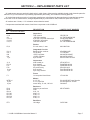
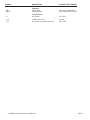
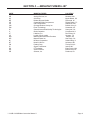
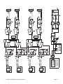
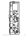
Logitek
2VUB & 4VUB
DUAL or QUAD
VU METER
Operation & Service Manual
All information contained herein is confidential. No portions of this manual
may be reproduced by any means without written permission from Logitek
Electronic Systems, Inc.
COPYRIGHT 1994, LOGITEK ELECTRONIC SYSTEMS, INC.
2VUB & 4VUB Mechanical Meters
Instruction Manual
Table of Contents
SECTION 1 — GENERAL INFORMATION
1-1
1-2
1-3
1-4
1-5
General Description . . . . . . . . . . . . . . . . . . . . . . . . . . . . . . . . . . . . . . . . . . . . . . . . . . 3
Physical Description . . . . . . . . . . . . . . . . . . . . . . . . . . . . . . . . . . . . . . . . . . . . . . . . . 3
Electrical Specifications . . . . . . . . . . . . . . . . . . . . . . . . . . . . . . . . . . . . . . . . . . . . . . . 3
Instrument Identification . . . . . . . . . . . . . . . . . . . . . . . . . . . . . . . . . . . . . . . . . . . . . . 3
Where to Find Help . . . . . . . . . . . . . . . . . . . . . . . . . . . . . . . . . . . . . . . . . . . . . . . . . . 3
SECTION 2 — PREPARATION FOR USE
2-1
2-2
2-3
2-4
2-5
2-6
2-7
2-8
Initial Inspection . . . . . . . . . . . . . . . . . . . . . . . . . . . . . . . . . . . . . . . . . . . . . . . . . . . . . 4
Claims . . . . . . . . . . . . . . . . . . . . . . . . . . . . . . . . . . . . . . . . . . . . . . . . . . . . . . . . . . . . 4
Repacking for Shipment . . . . . . . . . . . . . . . . . . . . . . . . . . . . . . . . . . . . . . . . . . . . . . 4
Mechanical Installation . . . . . . . . . . . . . . . . . . . . . . . . . . . . . . . . . . . . . . . . . . . . . . . 4
Connections to Rear Panel Terminal Block . . . . . . . . . . . . . . . . . . . . . . . . . . . . . . . . 4
Balanced and Unbalanced Audio Connections . . . . . . . . . . . . . . . . . . . . . . . . . . . . . 4
Setting “O VU” Level . . . . . . . . . . . . . . . . . . . . . . . . . . . . . . . . . . . . . . . . . . . . . . . . . 4
Phase Button . . . . . . . . . . . . . . . . . . . . . . . . . . . . . . . . . . . . . . . . . . . . . . . . . . . . . . . 4
SECTION 3 — PRINCIPLES OF OPERATION
3-1
3-2
3-3
3-4
General Information . . . . . . . . . . . . . . . . . . . . . . . . . . . . . . . . . . . . . . . . . . . . . . . . . . 5
Access to Circuit Cards . . . . . . . . . . . . . . . . . . . . . . . . . . . . . . . . . . . . . . . . . . . . . . . 5
Power Supply . . . . . . . . . . . . . . . . . . . . . . . . . . . . . . . . . . . . . . . . . . . . . . . . . . . . . . 5
Meter Circuits . . . . . . . . . . . . . . . . . . . . . . . . . . . . . . . . . . . . . . . . . . . . . . . . . . . . . . 5
SECTION 4 — REPLACEMENT PARTS LIST
4-1 2VUB & 4VUB Meter . . . . . . . . . . . . . . . . . . . . . . . . . . . . . . . . . . . . . . . . . . . . . . . . . 6
SECTION 5 — MANUFACTURERS LIST
SECTION 6 — DIAGRAMS
** 2 VUB & 4VUB Meter Instruction Manual **
Page 3
SECTION 1 — GENERAL INFORMATION
1-1 General Description
1-5 Where to Find Help
The 2VUB dual meter unit contains two lighted VU
meters in a self powered box. The 4VUB quad meter
unit contains four lighted VU meters in a self powered
box. Each meter has a high impedance balanced input
with an adjustable gain control.
Logitek customer service personnel are available
to help with any questions, comments or problems you
might have with the 2VUB or 4VUB meter, both during
and after the warranty period. Our hours of operation
are 8AM to 5PM central time. We may be contacted in
one of the following ways.
1-2 Physical Description
The 2VUB & 4VUB enclosure is 3 1/2 inches tall
and mounts in a standard nineteen inch rack enclosure. Audio and power connections are made to the
rear panel of the unit.
By Phone:877-231-5870 (USA & Canada)
or 713-64-4470
1-3 Electrical Specifications
By E-mail:
Frequency Response:
20 hz - 20 khz
+-0.5 dB
Overall Gain:
minimum
10 dB
Input Levels:
normal
maximum
0 dBu
+23 dBu
Input Impedance:
balanced:
Dimensions:
meter bridge
By Fax:
713-64-4479
[email protected]
By Mail: Logitek Electronic Systems, Inc.
5622 Edgemoor Drive
Houston, Texas 77081
USA
50,000 ohms
3 1/2" H x 19" W x 6" D
1-4 Instrument Identification
All Logitek 2VUB & 4VUB meters are identified by a
serial number. This serial number appears on a label
located on the back panel near the power cord. All correspondence to your Logitek representative or to the
Logitek factory concerning your meter should include
this serial number.
** 2VUB & 4VUB Meter Instruction Manual **
Page 4
SECTION 2 — PREPARATION FOR USE
2-1 Initial Inspection
Check the shipping carton carefully for external
damage. If the carton shows evidence of abuse, ask
the carrier’s agent to be present when the unit is unpacked. Carefully unpack the unit to avoid damaging
the equipment through the use of careless procedures. Inspect all equipment for damage immediately
after unpacking. Bent and broken parts, dents, and
scratches should be noted. If damage is found, refer to
paragraph 2-2 for recommended claim procedures.
Keep all packing material for possible future use.
2-2 Claims
If the unit has been damaged, notify the carrier immediately. File a claim with the carrier and advise Logitek of such action to arrange for repair or
replacement without waiting for a claim to be settled
with the carrier.
2-3 Repacking for Shipment
If the unit must be returned to Logitek, attach a letter to it showing the owner’s name and address. A description of the necessary service should be included
in the letter. The original shipping carton and packaging materials should be used for reshipment if possible. Use FRAGILE labels on each surface. Return the
unit freight prepaid. Be sure to insure the unit for its full
value. The unit will be repaired promptly and returned
freight prepaid.
2-4 Mechanical Installation
The 2VUB & 4VUB are designed to be bolted into a
standard nineteen inch equipment rack using the four
front panel mounting holes.
Unbalanced line-level sources (such as phono jack
outputs) can be fed to the 2VUB or 4VUB by connecting the “hot” lead from the source to the “+” input pin on
the XLR connector and connecting the shield from the
source to the “-” input pin. If either the meter or the
source unit is not grounded, either by the third prong of
its power cord, or by a separate audio ground cable,
then an additional wire should be added to connect
the “-” input terminal on the meter to the nearest
ground terminal.
Care should be taken to be sure that cable shields
are connected to grounded equipment on only one
end of the cable. On any cable which connects two
pieces of equipment, of which both are grounded, the
cable shield must be left unconnected on one end, or
poor noise performance may result.
2-7 Setting “O VU” Level
The 2VUB & 4VUB units are factory adjusted so
that a 0 dBu balanced input to a meter will be displayed as “0 VU” on the meter dial. If a different input
level is used the meter “0" point may be set between
-10 dBu and +10 dBu by adjusting the trim controls located adjacent to each input connector.
2-8 Phase Button
A phase test button is provided for meters 1 & 2 and
another button is provided for meters 3 & 4 (on the
4VUB only). The phase test mode is active when a colored dot is visible in the cap of the push-on/push-off
button. The phase test displays the sum of the two inputs on the left meter and the difference of the two inputs on the right meter. If the sum level(left meter) is
larger than the difference level(right meter) then the
two inputs are probably phased correctly.
2-5 Connections to Rear Panel Terminal Block
Inputs are connected to the meters via XLR connectors on the rear panel. The terminal functions are
as follows.
Pin-1
Pin-2
Pin-3
Ground
Input +
Input -
2-6 Balanced and Unbalanced Audio Connections
Balanced sources can be connected to the 2VUB or
4VUB by following the “+”, “-” and “Ground” designations listed above. Note that all inputs are high impedance bridging. However, a 600 ohm resistor can be
strapped across any input that needs a low impedance.
** 2 VUB & 4VUB Meter Instruction Manual **
Page 5
SECTION 3 — PRINCIPLES OF OPERATION
3-1 General Information
* * * * * * * * * * WARNING * * * * * * * * * * *
Results will be greatly enhanced by making use of
all available diagnostic information, including the circuit descriptions in this section and direct help from
Logitek technicians, before attacking the circuitry with
wire cutters, soldering irons, hammers or other tools
of destruction!
****************************
Before attempting any repair or modification of the
2VUB or 4VUB, the technician should become thoroughly familiar with the circuit in question by reading
the technical description below and by studying the
accompanying diagrams. Engineers at the Logitek
factory will be happy to discuss all aspects of the circuitry, both during and after the warranty period.
3-2 Access to Circuit Cards
The meter circuitry can be accessed by removing
the unit’s top cover.
3-3 Power Supply
Power cord P12 is connected to the primaries of
transformer T1 via a 1/4 amp slow-blow fuse. The primaries are hooked in series for 220 volt operation or in
parallel for 110 volt operation by switch SW1. The secondaries of T1 are hooked in a center tap ground configuration to full-wave bridge rectifier RT1. The output
of RT1 is filtered by C14 & C15 and regulated to +/5Vdc by IC8 & IC9. The supplies are stabilized by C16,
C17 & C9, while D1 & D2 prevent damage to the regulators if the supply rails are shorted together.
3-4 Meter Circuits
The input to the far left-hand meter (meter 1) is connected to a RF lowpass filter formed by R9, R10, C1
and C2. The resistors also form a -9 dB pad with the input impedance of balanced receiver IC1. IC1 provides
an additional -6 dB pad between its input and output.
The pads allow +20 dBu input signals to be handled by
the +/- 5 volt supply rails.
When phase switch SW2 is in the inactive (non indicating) position, the output of IC1 is connected to meter driver IC5b via DC stripper C10 and resistor R22.
The 0 VU point of the meter may be set between -10
dBu and +10 dBu by adjusting the gain of IC5b via
feedback resistor R1. The output of IC5b directly
drives meter MTR1.
In the same way a signal at J2 drives MTR2 via IC2,
R21, SW2 and IC5a. The output of IC2 is also phase
inverted by IC6a.
When phase switch SW2 is in the active (indicating)
position MTR1 is fed the sum of input1 and input2 via
resistors R19 and R20. MTR2 is fed the sum of input1
and phase inverted input2 via resistors R17 and R18.
If the in-phase sum is larger than the out-of-phase
sum then the inputs are in correct phase with each
other.
Meters 3 and 4 (on the 4VUB only) are driven in the
same way as meters 1 and 2.
* * * * * * * SAFETY WARNING * * * * * * *
Do NOT replace fuses without first disconnecting
power to the console to avoid shock hazard. ALWAYS
use fuses of the same value as that specified in this
manual. Do NOT use slow-blow types except where
specified. Do NOT use fuses of higher value than that
specified. Improper fuses may cause fire and shock
hazard as well as damage to the equipment.
A blown fuse is most often, though not always, a
symptom of another failure. Therefore, related circuitry should be examined carefully, especially if a
fuse blows more than once.
***************************
** 2VUB & 4VUB Meter Instruction Manual **
Page 6
SECTION 4 — REPLACEMENT PARTS LIST
All replacement parts are stocked in depth at the Logitek factory. Most are also available through local electronic parts distributors. For your convenience in purchasing replacement parts locally, we include the following parts list.
All Logitek part numbers consist of a two-letter manufacturer code followed by that manufacturer’s standard part number
for the item. A list of manufacturers, arranged alphabetically by manufacturer code, follows this parts list in Section 7.
All resistors are 1/4 watt, +/- 5% tolerance unless otherwise noted.
Components associated with meters 3 and 4 are not present on the 2VUB unit.
SYMBOL
4-1
2VUB & 4VUB Meter
DESCRIPTION
LOGITEK PART NUMBER
C1-8
C9
C10-13
C14,15
C16,17
Capacitors
75pf ceramic
.22uf/50V tantalum
47uf/10V non-polar electrolytic
470uf/25V electrolytic
10uf/25V tantalum
CE-DD-750
AV-TAP224K050CCS
NI-UES1A470MPJ
IL-477RMR025
AV-TAP106K025HSB
D1,2
Diodes
5.6 volt zener, 1 watt
MO-1N4734A
IC1-4
IC5-7
IC8
IC9
7 pc.
Integrated Circuits
Balanced line receiver
Fet op amp
-5VDC regulator
+5VDC regulator
8-pin socket
AD-SSM2143P
TI-TLO72CP
MO-MC79L05ACP
MO-MC78L05ACP
EM-100-083-10-1005
J1-4
P5-10
P11
P12
6 pcs.
1 pc.
Connectors
XLR female pc
6-pin header
3-pin large header
AC power entry
6-pin socket
3-pin large socket
NT-NC3FK-H
PN-MFSS100-6A
PN-MFSS156-3A
SR-6200.4115
PN-CE100F28-6A
PN-CE156F20-3A
F1
Fuses
1/4 amp slow blow 20mm
LF-218.250
MTR1-4
4 pcs.
4 pcs.
Meters
2 1/2" VU
2 1/2" Light Box
meter lamp, 12 volt, 100 mA
SO-AL29R WF bezel,b-scale
SO-29/Light box 12VDC
CM-8918
R1-4
R5-8
R9-16
R17,20
R21,22
R23-30
R31,32
Resistors
50K trim pot muli-turn
3300
21K, 1%
4220, 1%
2100, 1%
4220, 1%
2100, 1%
RT1
Rectifiers
1A bridge
** 2 VUB & 4VUB Meter Instruction Manual **
MP-CT9X503
GI-DF10M
Page 7
SYMBOL
DESCRIPTION
LOGITEK PART NUMBER
SW1
SW2,3
Switches
DPDT slide
2P pushbutton
CK-L202-121MS-02QE
SH-ZF142ueetb-01011201
T1
Transformers
8V 750mA
SI-IF-6-16
1 pc.
1 pc
4VUB meter driver
IEC power cord (North America)
LG-246
BE-17251
** 2VUB & 4VUB Meter Instruction Manual **
Page 8
SECTION 5 — MANUFACTURERS LIST
CODE
MANUFACTURER
LOCATION
AD
AV
BE
CE
CK
CM
EM
GI
IL
LF
LG
MO
MP
NI
NT
PN
SI
SH
SO
SR
Analog Devices, Inc.
AVX Corp.
Belden Wire and Cable
Centralab/Philips Components
C&K Components
Chicago Miniature Lamp, Inc.
Ecam Technology
General Instruments/Quality Technologies
Illinois Capacitor
Littlefuse, Inc.
Logitek (Circuit cards)
Motorola Semiconductor Products
Mepco/Electra Inc.
Nichicon Corporation
Neutrik USA Inc.
Panduit Corp.
Signal Transformer
ITT Schadow
Selco Products
Schurter, Inc.
Norwood, MA
Myrtle Beach, SC
Richmond, IN
Riviera Beach, FL
Watertown, MA
Buffalo Grove, IL
Scottsdale, AZ
Sunnyvale, CA
Lincolnwood, IL
Des Plaines, IL
Houston, TX
Phoenix, AZ
San Diego, CA
Schaumburg, IL
Lakewood, NJ
Tinsley Park, IL
Inwood, NY
Eden Prairie, MN
Buena Vista, CA
Petaluma, CA
** 2 VUB & 4VUB Meter Instruction Manual **
Page 9
SECTION 6 — DIAGRAMS
** 2VUB & 4VUB Meter Instruction Manual **
Page 10
** 2 VUB & 4VUB Meter Instruction Manual **
Page 11
** 2VUB & 4VUB Meter Instruction Manual **
Page 12
Logitek
TWO YEAR LIMITED WARRANTY
Logitek Electronic Systems, Inc. warrants its professional equipment (excluding Logitek Software,
which is covered by a separate warranty) against defects in materials and workmanship for two years pursuant to the following terms and conditions. The
warranty extends to the original purchaser only.
LOGITEK will repair or replace, at its option, at its
factory without charge professional equipment if a defect in materials or workmanship develops during the
first two years following purchase, when the equipment is returned to the factory or LOGITEK authorized
service centers freight prepaid with a description of
the nature of the failure. No reimbursements can be
made for repair charges that are not factory authorized. After repair or replacement, LOGITEK will return the equipment to the purchaser freight prepaid.
In the event that any part of this professional equipment becomes defective during the first two years following purchase, and purchaser wishes to attempt
repair, purchaser may obtain a replacement part by
notifying LOGITEK of the part of the equipment which
has failed. LOGITEK will thereafter ship a replacement part, freight prepaid. LOGITEK may require the
purchaser to return the defective part to LOGITEK
freight prepaid as a condition of such replacement, either before or after LOGITEK ships the replacement
part. LOGITEK shall not be responsible for any other
c h a r g e s o r l i a b i l i t i e s a s s o c i a t e d w i t h p u rchaser--made repairs.
No part or equipment shall be considered defective
if it fails to operate due to exposure to extreme temperatures or excessive moisture in the atmosphere.
Light bulbs, batteries, potentiometers or other
equipment not manufactured by Seller shall carry only
the warranty, if any, of the original equipment manufacturer in effect at the time of shipment of this order;
and Seller’s obligation under this warranty shall be
limited to such adjustment as Seller may obtain from
the original manufacturer.
This limited warranty is void if equipment is modified or repaired without authorization; subjected to
misuse, abuse, accident, water damage or other ne-
** 2 VUB & 4VUB Meter Instruction Manual **
glect; or has had its serial number defaced or
removed.
No obligation is assumed by LOGITEK to update
previously manufactured equipment. Specifications
are subject to change without notice. EXCEPT AS
SPECIFICALLY PROVIDED HEREIN, LOGITEK
MAKES NO WARRANTY, REPRESENTATION,
PROMISE, OR GUARANTEE, EITHER EXPRESS
OR IMPLIED, STATUTORY OR OTHERWISE, WITH
RESPECT TO THE EQUIPMENT, USER DOCUMENTATION OR RELATED TECHNICAL SUPPORT, INCLUDING THEIR QUALITY, PERFORMANCE,
MERCHANTABILITY OR FITNESS FOR A PARTICULAR PURPOSE. IN NO EVENT WILL LOGITEK BE
LIABLE FOR INDIRECT, SPECIAL, INCIDENTAL,
TORT, ECONOMIC, COVER, OR CONSEQUENTIAL
DAMAGES ARISING OUT OF THE USE OF OR INABILITY TO USE LOGITEK PRODUCTS, EQUIPMENT, OR SERVICES, INCLUDING, WITHOUT
LIMITATION, DAMAGES OR COSTS RELATING TO
THE LOSS OF PROFITS, BUSINESS, GOODWILL,
DATA OR COMPUTER PROGRAMS, EVEN IF
ADVISED OF THE POSSIBILITY OF SUCH DAMAGES. IN NO CASE SHALL LOGITEK ‘S LIABILITY
FOR MONEY DAMAGES EXCEED THE AMOUNT
PAID BY YOU FOR THE LOGITEK EQUIPMENT
OUT OF WHICH SUCH CLAIM AROSE. THE
FOREGOING LIMITATIONS SHALL NOT APPLY TO
CLAIMS RELATING TO DEATH OR PERSONAL INJURY WHICH ARISE OUT OF PRODUCTS DEEMED
TO BE CONSUMER GOODS UNDER APPLICABLE
LAW.
Some states or provinces do not allow the exclusion or limitation of implied warranties or limitation of
liability for incidental or consequential damages, so
the above exclusion or limitation may not apply to you.
The warranty and remedies set forth herein are exclusive and in lieu of all others, oral or written, express
or implied. No Logitek dealer, distributor, agent, or
employee is authorized to make any modification or
addition to this warranty.
Page 13