1
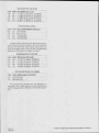
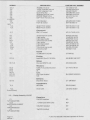
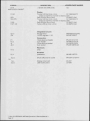
Logitek Software License Agreement
The Ultra-VU unit you have purchased contains embedded software.
The software is owned by Logitek Electronic Systems, Inc. and is protected by United States copyright laws and international treaty provisions.
Logitek grants to you the right to use one copy of the embedded software in each Ultra-VU meter you purchase. You may not rent or lease the
software. You may not reverse engineer, decompile, disassemble, or
create derivative works from the software. You may not create copies of
the software.
This statement will be governed by the laws of the State of Texas,
U.S.A. Logitek reserves all rights not specifically granted in this statement.
All information contained herein is confidential. No portions of this manual may be reproduced by any means without written permission from
Logitek Electronic Systems, Inc.
COPYRIGHT 1996, LOGITEK ELECTRONIC SYSTEMS, INC.
kfiltek
•
Electronic Systems, Inc.
3320 BERING DRIVE 0 HOUSTON, TX 77057 USA 0 800-231-5870 (OUTSIDE USA &
CANADA 713-782-4592)n FAX 713-782-7597
ULTRA-VU NBC896 & NBC996
OPERATION & SERVICE MANUAL
TABLE OF CONTENTS
SECTION 1- GENERAL INFORMATION
1-1 General Description 1-2 Electrical Specifications 1-3 Standards 1-4 Instrument Identification 1-5 Where to Find Help SECTION 2 - PREPARATION FOR USE
2-1Initial Inspection 2-2 Claims 2-3 Repacking for Shipment 2-4 Installation 2-5 Connecting Mains Power 2-6 Connecting Audio Inputs 2-7 Alarm System (UV2-RD-NBC896 only) 2-8 Rear Panel Programming Switches SECTION 3 - OPERATING INSTRUCTIONS
3-1 Bargraph Description 3-2 VU Display 3-3 PPM
Displ ay 3-4 Peak Hold Dis p lay 3-5 LOUD — Loucness Filter 3-6 I-S — Image/Sum Display 3-7 FINE — High Resolution Mode 3-8 Auxiliary Date Display 3-9 Changing Display Brightness 3-10 CLIP indicator set point 3-11 Resetting the Program SECTION 4 - MAINTENANCE
4-1 General Information 4-2 Fuse 4-3 Handling of CMOS Integrated Circuits 4-4 Access to Circuit Cards 4-5 Power Supply LG-253 4-6 Dual Digital/Alarm Card LG-257a 4-7 Display Assembly LG-267 SECTION 5 - REPLACEMENT PARTS LIST
5-1 Power Supply LG-253 5-2 Dual Digital/Alarm Card LG-257a 5-3 Display Assembly LG-267 SECTION 6 - MANUFACTURERS LIST
SECTION 7 - DIAGRAMS
3
3
3
3
3
4
4
4
4
4
4
4
4
6
6
6
6
6
6
7
7
7
7
7
8
8
8
8
8
8
9
10
10
11
SECTIO N
1 GENERAL INFORMATION
The one exception to these standards is the PPM
tra-VU uses a true peak measureattack time. The Ul
t. .peak
sti• n
1I D
ment scheme that always displays the highes
The Logitek Ultra-VU is a bargraph type audio meof the input signal. The PPM standard specifies a
ter featuring two tri-color LED bargraphs with clip inshort averaging period for peak signals that keeps
dicators. Two function buttons and several auxiliary
to be heard well from
sounds with durations too short
data indicators are also included on the front panel.
being displayed, no matter how loud they are. The
delay also allows mechanical meters to keep up with
1-2 Electrical Specifications
fast changing inputs. Under most circumstances
Twothere is no noticeable difference between true peak
Bargraphs per meter:
63 and PPM peak readings. However, if you do need the
Indicators per bargraph:
Ultra-VU to conform to the PPM peak standard then
Normal Range: -70 dB to 0 dB plus clip - digital
please contact the Logitek factory for further informa-50 dB to + 20 dB plus clip - analog
tion.
Fine Range:.2 dB per segment around ref pt.
Reference Point:-10,-12,-14,-16,-18 or -20 dB
1-4 Instrument Identification
Peak Markers:
8,9,10,12,14,16,18 dB above ref pt
Ballistics:
VU Mode300 mS/20dB attack & release
PPM Mode0 mS attack, 2.8S/24dB release
Peak Hold0 mS attack, 2 or 5 Second hold
Max Hold0 mS attack, pushbutton release
Image/Phase4 Sec hold on max image
Clip Indicator:trigger on 1 or 4 consecutive
clipped samples
Frequency Response:
Normal
+/-.1 dB 20 Hz - 20 KHz
Loudness Filter58 dBSPL auditory curve
-40 dB 20 Hz, 0 dB 1250 Hz, -50 dB 20 KHz
Brightness control:
Digital Input:
Formats
Impedance
Termination
8 levels
AES/EBU or S/PDIF
75 Ohm (BNC)
transformer balanced
Power Requirement:
Dimensions:
1-5 Where to Find Help
Logitek customer service personnel are available
to help with any questions, comments or problems
you might have with the Ultra-VU meter, both during
and after the warranty period. Our hours of operation
are 8AM to 5PM central time. We may be contacted in
one of the following ways.
By Phone:800-231-5870 (USA & Canada)
or 713-782-4592
By Fax:
By Email:
By Mail:
AC Line Input Voltage:
50-60 Hz
(switch settable)
The Ultra-VU is identified by a model number and
a three or four digit serial number. The model number
and serial number appear on a label on the back of
the unit near the power cord. All correspondence to
your Logitek dealer or to the Logitek factory should
refer to the model number and serial number.
105-129 VAC or
220-240 VAC
713-782-7597
help @logitekaudio.com
Logitek Electronic Systems, Inc.
3320 Bering Drive
Houston, Texas 77057
USA
20 Watts
19" W x 7" D x 1 3/4" H
1-3 Standards
The Ultra-VU meters are designed to conform to
the ballistic standards described in IEEE document
G.2.1.2/13, IEC document 268 and EBU document
3205-E. This ensures that the bargraph motion will
closely track other standard mechanical and electronic meters.
Page 3
Manual ""
** Ultra-VU NBC896 & NBC996 Operation & Service
SECTION 2 PREPARATION FOR USE
2-1 Initial Inspection
Check the shipping carton carefully for external
damage. If the carton shows evidence of abuse, ask
the carrier's agent to be present when the unit is unpacked. Carefully unpack the unit to avoid damaging
the equipment through the use of careless procedures. Inspect all equipment for damages immediately after unpacking. Bent and broken parts, dents
and scratches should be noted. If damage is found,
refer to paragraph 2-2 for recommended claim procedures. Keep all packing material for possible future
use.
2-2 Claims
If the unit has been damaged, notify the carrier immediately. File a claim with the carrier and advise Logitek of such action to arrange for repair or
replacement without waiting for a claim to be settled
with the carrier.
2-3
Repacking for Shipment
Normally the A input is displayed on the meter and
checked for errors by the alarm section. To check
and display the B input connect the switch 1 terminal
to the switch common terminal on the rear panel terminal block. Note that the switch inputs are surge
protected but not ground isolated and should be kept
within 5 volts of the enclosure.
2 - 7 Alarm System
(UV2-RD-NBC896 only)
Three elements of the active input are constantly
checked for errors. A dry contact relay closure is activated if an overmodulation, undermodulation or
phase reversal problem is detected. The relay contacts are accessed via a rear panel terminal block.
Also, a front panel indicator will light if any alarm is
active.
Trip points for over and under modulation are provided as well as variable delay times before an alarm
is activated.
The phase display triggers if the left-to-right phase
relationship is more than 2/3 out of phase and is not
adjustable.
If the unit must be returned to Logitek, attach a letter to it showing the owner's name and address. A description of necessary service should be included in
the letter. The original shipping carton and packaging materials should be used for reshipment if possible. Use FRAGILE labels on each surface. Return
the unit freight prepaid. Be sure to insure the unit for
its full value. The unit will be repaired promptly and
returned freight prepaid.
Normally an alarm will reset as soon as the error
causing it stops. However, the alarms will latch on
and not reset if jumper P8 is removed. P8 is located
on the control card nerar the center. It is accessed by
removing the meter top cover. When in latching
mode is active, an alarm will remain active until the
switch 2 input on the rear panel terminal block is connected to the switch common pin.
2-4 Installation
2-8 Rear Panel Programming Switches
The Ultra-VU rackmount models are designed to
be mounted in a standard 19" equipment rack by using the four mounting holes in the corners of the front
panel. Plastic washers should be used to keep the
mounting screw for marring the front panel finish.
A block of eight mode setting switches is located
on the rear panel of the meter to the right of the input
BNC connectors. The switches are numbered 1
through 8 and are set by pushing the white levers up
or down with a small screwdriver or pen point.
2-5 Connecting Mains Power
The orange bargraph zero reference marker and
the reference level of the fine display is set via switch
8 as shown.
Connect the meter to the power mains with the enclosed power cord. The unit is factory set for 115VAC
operation unless specifically labeled otherwise, but
230VAC operation can be selected via a slide switch
located next to the power transformer inside the unit.
To gain access to the voltage select switch, remove
the enclosure top cover. The switch is located adjacent to the large power transformer.
2-6 Connecting Audio Inputs
The Ultra-VU accepts two inputs per meter via 75
ohm female BNC connectors on the rear panel. The
input format is AES/EBU or S/PDIF serial data at
sample rates of 30,000 to 50,000 samples per second.
Zero Reference Setting
Sw8 dBs below full scale
Up -18 dB
Dn -20 dB
An alarm will be activated when the average signal
level of either channel exceeds the overmod trip
point at least once every 5 mSec during the entire
alarm delay period. The trip point and delay time is
set via the programming switches and the alarm is
output on relay 1.
"* Ultra-VU NBC896 & NBC996 Operation & Service Manual **
Page 4
Overmod Alarm Trip Point
Sw1 1 Sw2 dBs below full scale
1 Up Up -17 dB (+3 dB above -20 dBFS)
Up Dn -14 dB (+6 dB above -20 dBFS)
Dn Up
-11 dB (+9 dB above -20 dBFS)_
Dn IDn -8 dB (+12 dB above -20 dBFS)
Overmod Alarm Delay
Sw3 Sw4 delay before alarm activates
1LUp Up 30 seconds
Up _ Dn 60 seconds
Dn Up 120 seconds
Dn ,Dn 180 seconds
An alarm will be activated when the average signal
level of either channel remains under the undermod
setpoint for the entire alarm delay period.The trip
point and delay time is set via the programming
switches and the alarm is output on relay 2.
Undermod Alarm Trip Point
Sw5 Sw6 dBs below full scale
Up Up -35 dB (-15 below -20 dBFS)
Up Dn _ -40 dB (-20 below -20 dBFS)
i Dn Up -50 dB (-30 below -20 dBFS)
i [Dn Dn -60 dB (-40 below -20 dBFSL
Undermod & Phase Alarm Delay
Sw7 delay before alarm activates
Up 1120 Seconds
Dn 1240 Seconds
The programming switches are only checked occasionally, so it may take up to two seconds for
switch changes to be reflected in the meter's operation.
Page 5
Manual —
** Ultra-VU NBC896 & NBC996 Operation & Service
SECTION 3 OPERATING INSTRUCTIONS
3-1 Bargraph Description
3-4 Peak Hold Display
The Ultra-VU display contains two multi-LED bargraph displays mounted one above the other. The
top bar shows either left channel (L) or im age/phase(0 information. The bottom bar shows either right channel (R) or mono sum (S) information.
The bars are marked at the left end to indicate their
function. The tri-color LEDs can be green, red or orange depending on their function and cover the
range from -70 dBFS to 0 dBFS.
The peak hold display is a single red segment that
maintains the highest PPM reading for a user selectable amount of time. If the holding period expires
before the PPM dot equals or exceeds the peak hold
dot, then the peak hold dot will turn off. It will turn on
again when the PPM dot reaches a peak and starts
falling again.
The top LED of each bar is larger and red only. It is
used as a clipping indicator and can be set to illuminate on any clipped signal or only after four consecutive clipped samples.
The zero reference point of the meter is indicated
by a dim orange marker in the bargraph. The reference mark can be varied between -18 and -20 dBFS
via a switch on the back panel.
Two holding modes are available. Release (Rel)
mode holds the peak reading for 2 seconds. Maximum (Max) mode holds the highest peak reading until it is manually reset by turning the peak hold off and
then on again.
Peak hold can be cycled through Off, Rel and Max
modes by repeatedly pressing the HOLD button at
the lower right corner of the meter front panel.
3-5 LOUD — Loudness Filter
The meter has two stereo inputs. Normally the A
input is displayed. If the B input is being displayed a
light next to the "B IN" legend will light. The meters
may also have error detection software installed. If a
problem is detected a light next to the "ALARM" legend will light.
The VU display can be compensated to match the
frequency response of the human ear by enabling the
loudness filter. This will cause the VU bars to more
closely represent the actual loudness perceived by
the listener and allow better level matching between
different kinds of program material.
3-2 VU Display
The loudness filter is calibrated for a listening level
of 58 dB SPL. The filter will be less accurate for listening levels above and below this point.
VU is indicated by a solid green bar below 0 VU
and a solid red bar above 0 VU. VU represents the
perceived loudness of the input signal. The motion of
the bars conforms to the industry standard 300 mSec
per 20 dB rise and fall times. Note that the speed of
the bar will appear faster near the top of the meter
display because each segment there represents
fewer dBs than at the bottom of the meter. The VU
display can be turned off by pressing the MODE button at the bottom left corner of the front panel repeatedly until the VU bars disappear.
3-3 PPM Display
Peak program meter (PPM) information is shown
by a single red segment. PPM represents the highest
point of the input signal. The display has a zero rise
time and an industry standard 2.8 Sec per 24 dB fall
time. The dot will appear to fall faster near the top of
the meter range because each segment there represents fewer dBs than at the bottom of the meter. The
PPM display is always active unless it is turned off by
the programming switches on the back panel.
The VU and PPM displays are calibrated so that
they will read the same when connected to sine wave
signals. The red PPM dot will be on top of the highest
green segment of the VU bar resulting in a bright orange dot. For dynamic signals the difference between the top of the VU bar the the PPM dot is
approximately the crest factor.
To activate the filter, press the MODE button in the
lower left corner of the meter front panel until the
"Loud" indicator is lit.
Users of the digital input meters should note that
filtering is a function of sample rate. The meter has a
separate filter for each of the five sample rates listed
on the front panel. If a non listed sample rate is used
the loudness filter will be deactivated.
3-6 I-S — Image/Sum Display
The image and sum displays are activated by
pressing the MODE button in the lower left corner of
the meter front panel until the "43," indicator if lit.
In this mode, the lower bargraph displays the
mono sum of the left and right input channels. The
display operates identically to the left and right bargraphs except that the loudness filter is not available.
The upper bargraph shows the stereo image and
relative phase information. Three orange markers
are located at 90 degrees left, 0 degrees center and
90 degrees right. The scale covers 180 degrees
which is the largest relative phase difference two signal can have.
The red dot indicates the current location of the left
channel in the stereo sound field and the green dot indicates the current location of the right channel in the
** Ultra-VU NBC896 & NBC996 Operation & Service Manual **
Page 6
stereo sound field. The overall width and location of
the stereo image is shown by a second pair of red and
green segments that hold the furthest left and right
readings for about four seconds.
becomes corrupted, the meter will probably fail to
operate. In most cases, an independent watchdog
circuit will notice that the meter is working incorrectly
and restart the system.
If a mono signal is being displayed, then the red
and green segments will be at the same location resulting in a dot that looks orange. If the mono signal
is off center (such as left channel only), the resulting
orange dot will be off to one side of the display.
The processor can be reset manually by turning
the power off and then back on again.
3-7 FINE — High Resolution Mode
Fine is a high resolution mode that expands the
meter scale to .2 dB per segment around the 0 VU
point. This mode is useful when doing precise alignments using steady state signals. Fine is activated by
pressing the MODE button at the bottom left of the
meter front panel until the FINE indicator lights..
3-8 Auxiliary Date Display
Ultra-VU models with serial digital inputs provide
information about the input data format via indicator
lights along the bottom of the meter front panel. This
information is for the active channel only.
EMPH indicates pre-emphasis has been applied
to the audio and is recovered from the embedded
channel status data. The circle is lit only when emphasis is detected. The indicator is accurate with
both AES/EBU and S/PDIF input formats.
PRO indicates whether the data stream is in the
professional or consumer format and is recovered
from the embedded channel status data. The circle is
lit only when the AES/EBU professional format is detected.
3-9 Changing Display Brightness
The overall illumination level of the meter can be
set to one of eight levels. To change the brightness
level, press the MODE button until the BRT indicator
lights. Then press the HOLD button until the desired
illumination level is achieved.
3-10 CLIP indicator set point
The large red clip segment at the top of each bargraph can be set to light on the reception of either one
or four clipped samples in a row. To change the setting press the MODE button until the CLIP indicator
along the bottom of the meter lights. A segment in the
lower bargraph will start to blink alternately red and
green to indicate the current setting. Press the HOLD
button until the desired setting is shown on the bargraph.
3-11 Resetting the Program
The Ultra-VU contains software that executes on a
programmable DSP chip. If the processor memory
Page 7
Manual **
** Ultra-VU NBC896 & NBC996 Operation & Service
SECTION 4 MAINTENANCE
4-1 General Information
* ***************************
The Ultra-VU is designed to need a minimum of
maintenance for long trouble-free operation. Should
repair be necessary, the technician should first read
the information in the manual concerning the circuits
in question and should follow proper procedures for
testing and replacing semiconductors. Logitek engineers are readily available at the factory to provide
technical assistance both during and after the warranty period.
* * * * * * * * * * WARNING * * * * * * * * * * *
4-4 Access to Circuit Cards
The inside of the Ultra-VU contains no controls or
user serviceable parts. The cover should only be removed by competent technical personnel capable of
servicing this type of equipment. Hazardous voltages
exist on the underside of some circuit cards.
****************************
4-2 Fuse
The primary winding of the power transformer is
fused with a 1/2 amp slow-blow 20mm fuse housed in
a fuse holder in a slide-out drawer under the power
cord on the rear panel of the unit. It should only be replaced with fuses of the same type and current rating.
The power cord must be unplugged from the rear
panel to gain access to the fuse holder.
* * * * * * * * * * WARNING * * * * * * * *
Do NOT replace the fuse without first disconnecting the meter's power cord from the wall socket, as
dangerous voltages are present which may cause
electrical shock. Always use fuses of the same value
and type as specified in this manual. Do NOT use
fuses of a higher value than those specified, as shock
hazard and fire hazard may result.
* ***************************
A blown fuse is most often, although not always, a
symptom of another failure. Related circuitry should
always be carefully examined after any fuse failure,
especially if a replacement fuse also blows.
4-3 Handling of CMOS Integrated Circuits
All logic components in the Ultra-VU meter are
CMOS type integrated circuits. Even though all circuits have built in static discharge protection, special
care must be taken in the handling of these devices,
particularly in dry environments.
* * * * * * * "
IMPORTANT * * * * ** *'
Do NOT remove or handle CMOS integrated circuits except in a grounded environment which is free
of the risk of static electricity. Store such circuits on
conductive foam or in anti-static controllers. Do NOT
store on styrofoam or other plastic sheets. Improper
handling may damage these devices.
Access to the circuitry of the rackmount meters is
accomplished by removing the eight screws that attach the top cover.
4-5 Power Supply LG-253
Each Ultra-VU contains a ground isolated and filtered step-down power supply to create the necessary operating voltages. This supply is located on a
PCB on the right side of the meter enclosure.
Mains AC from the power entry module J2 is fed
through fuse Fl , located in a drawer under the power
cord in J2, to J1 on supply card LG-253. J1 feeds voltage selection switch S1 which connects the dual primaries of transformer T1 in series for 230VAC
operation or parallel for 115VAC operation. The dual
secondaries of T1 are wired in parallel and loaded
with a full-wave bridge rectifier RT1. The DC output
of RT1 is filtered by capacitors C1 and C2 and fed to
the red and green output pads. The voltage should be
between 8 to 10 VDC with less than .5 volt of ripple.
Analog input models will also have a charge pump
consisting of 101 and C3 that feeds filter C4 and the
black output pads. The voltage should be -8 to -10
VDC with less than .1 volt of ripple.
Jumpers soldered to the output pads feed power
to one or two meter control cards.
* * * * * * * * * * w ARNING * * * * * * * * * * *
Dangerous voltages are present on the bottom of
the power supply card. Always disconnect the AC
power cord when servicing this circuit board.
****************************
4-6 Dual Digital/Alarm Card LG-257a
Power from input connector P5 is connected to
voltage regulators IC3 and IC4 as well as display
board connectors P6 and P7. IC3 is a +5VDC regulator that feeds power to the analog front end of data receivers IC1 and IC2. The voltage is filtered by C5- C9
and clamped against over voltage and voltage reversal by D2. IC4 is a +5VDC regulator that feeds the
digital portion of 101 and IC2 and all other circuits on
the control board. The output voltage is filtered by
010 and clamped by D3. Distributed power filtering is
supplied by 011-14.
On power up, the DSP is kept in reset by IC6 until
the power has stabilized, ensuring a good power on
reset. IC6 also contains a watchdog timer that will reset the DSP if its ST pin in not taken low at least once
every 150 mSec. This pin is normally pulsed low
every 5 mSec by the left bargraph load signal.
The DSP (IC8) is clocked by a 12.288 MHz crystal
oscillator consisting of Y1,C15,C16 and an internal
** Ultra-VU NBC896 & NBC996 Operation & Service Manual **
Page 8
driver. IC8, pin 43 is a buffered output of the oscillator.
The first thing the DSP (IC8) does after reset is
copy its program from EPROM IC7 to internal RAM
memory. That program executes continuously. Note
that the 8 bit data bus is connected to the middle byte
of the DSP's 24 bit data port.
The rear panel DIP switch S1-8 and the front panel
rocker switches S11 and S12 are connected to the
DSP data port via pull-up resistors R1, R2 and isolation resistors R10, R11.
Serial data is sent synchronously (data, clock,
load) to the display driver chips via the left/right display connector P7 and image/sum display connector
P6 in 16 bit strings. Data is placed on the top bit of the
DSP data port and clocked into the display drivers via
a write to address decoder IC9. Other writes to IC9
will load the 16 bit data string into one of the display
drivers on the display board. A write to the left bargraph will also be decoded by IC9 and used to reset
the watchdog timer.
Two channel audio data is fed synchronously
(data, clock, frame sync) from data receiver 101 to
DSP (108) serial port 1.
Encoded audio data enters the meter via BNC
connector J1, passes through ferrite beads FR1,FR2
and connects to pulse transformer T1 via DC blocking capacitor C1. The output of T1 is loaded by R5,R3
and connected to data receiver 101. C3 and R7 form
a loop filter used by 101 to recover the embedded
clock from the coded input signal. 101 separates the
audio data, channel data and clock from the input
data. The audio is sent to the DSP in 64 bit strings via
a serial port. Channel subcode data and the PLL lock
flag are connected to the DSP data bus via isolation
resistors R11.
lit. The driver chips can also selectively decode BCD
data into 7-segment numeric display signals. Maximum LED brightness is set by the external resistors.
The drivers further control brightness by pulse-width
modulating the LED on times with a value supplied by
the DSP.
The display drivers accept synchronous serial
data (clock, data, load) in 16 bit strings composed of
an address byte and a data byte. The driver ICs are
arranged in two chip groups. The data out of one chip
is hooked to the data in of the second chip such that 4
bytes can be loaded, two to each chip, with one load
pulse.
101 and IC2 drive the upper bargraph (left channel). IC3 and IC4 drive the lower bargraph (right
channel). IC5 drives the scale indicator LEDs along
the bottom edge of the display.
Avoid removing all three LED alignment plates if at
all possible. There is very little space around the indicator LEDs and, if any get bent, it can take some time
to reassemble the alignment plate. If a LED needs replacing, pry it out of its socket with a screwdriver and
remove it. Remember to consult the component diagram for the correct orientation before installing a
new LED. Also note that the tri-color LEDs are
graded according to color and brightness. A sticker
on the back of the PCB denotes the correct lot
number needed for reordering.
The second input is handled in an identical fashion
by IC2 and is connected to serial port 0 of the DSP.
Four bits of the data bus are stored in quad flip-flop
IC5 by a write to address decoder IC9. The outputs of
IC5 drive up to three SPST relays. The relay switch
contacts are sent to the rear panel alarm connector
via P3.
471_p_i_splay Assembly LG-267
Filtered power is connected to the driver card via
P1. +5VDC regulator IC6 is bolted to the meter enclosure to increase heat dissipation and connects to the
driver card via P2. C4 provides bulk power storage
while C1, C2, C3 and C5 through C8 stabilize the 5
volt supply.
Each display driver IC controls 64 LEDs by scanning them in an eight by eight matrix. Segment lines
are current controlled and connect to the LED anodes. Digit lines connect to the LED cathodes. Scanning is accomplished by taking each digit line low one
at a time and sourcing current from the segment lines
for whichever of the 8 LEDs in a digit group need to be
Page 9
Manual —
** Ultra-VU NBC896 & NBC996 Operation & Service
SECTION 5 REPLACEMENT PARTS LIST
All replacement parts are stocked in depth at the Logitek factory. Most are also available through local electronic
parts distributors. For your convenience in purchasing replacement parts locally, we include the following parts list.
All Logitek part numbers consist of a two-letter manufacturer code followed by that manufacturer's standard part
number for the item. A list of manufacturers, arranged alphabetically by manufacturer code, follows this parts list in
Section 7.
All resistors are 1/4 watt, +/- 5% tolerance unless otherwise noted.
BEEEYMBOL
5-1Power Supply LG-253
DESCRIPTION
LOGITEK PART NUM-
Capacitors
C1
C2
C3,4
6800 of/25V electrolytic
.1uf/50V ceramic disc
100uf/25V electrolytic
IL-688LBA025M2CD
NC-.100MF50ME2
NI-UFS1E101MPJ
Integrated Circuits
101
1 pc.
1003
Charge pump
8-pin dip socket
TI-LT1054CN
EM-100-083-10-
Rectifiers
RT1
6A pc mount/240V
Fuses
GI - GBPC - 602
LF - 218.500
Fl
1/2 amp slow blow 20mm P1
J1
J2
PN-MLSS156-3A
3-pin large header - locking
PN-CE156F20-3A
3-pin large socket
Power entry module/fuse holderSR-6200.4115
Connectors
S1
121 MS02QE
T1
1 pc.
1 pc.
Switches Slide DPDT
CK-L202-
Transformers
8V, 3A international rating
Super-VU Supply circuit card
Power card (North America)
SI-IF-24-16
LG-253C
BE-17251
5-2Dual Digital/Alarm Card LG-257a
Capacitors
C1,2
C3,4
C5-8
C9-11
TAP106K025HSB
C12-14
C15
C16
.1uf/50V ceramic
.047uf/1000V ceramic
.1uf/50V ceramic
10uf/25V tantalum
CE-UK50-104
CE-CW-20C473K
CE-UK50-104
AV-
.1uf/50V ceramic
25pf/1000V ceramic
15pf/1000V ceramic
CE-UK50-104
CE-DD-250
CE-DD-150
Diodes
D1-3
D4,5
GI-1 N4734A
small signal
5.4V zener
Integrated Circuits
— Ultra-VU NBC896 & NBC996 Operation & Service Manual **
Page 10
GI-1N4148
SYMBOL
IC1,2
IC3
IC4
IC5
IC6
IC7
IC8
2115KP55
IC9
1 pc.
1003
1 pc.
1 pc.
DESCRIPTION
LOGITEK PART NUMBER
AES/EBU receiver
+5VDC regulator/100 mA
+5VDC regulator/1.5A
Quad D flip-flop
Watchdog timer/uP reset
EPROM 16Kx8 120ns
DSP 16 bit 1 K/2 ser ports
CS-CS8412-CS
MO-MC78L05ACP
MO-MC7805CT
MO-MM74HC173D
MM-MAX12320PA
MC-27C 128-12/L
AD-ADSP-
3 to 8 decoder
8-pin dip socket
MO-MM74HCT138D
EM-100-083-10-
32-pin PLCC socket
68-pin PLCC socket
EM-150-032-11-02
EM-150-068-11-02
J1,2
Connectors
BNC PC mount
AP-31-71043-1010
P3
P4
P5
P6,7
P8
1 pc.
1 pc.
2 pcs.
1 pc.
10-pin dual row socket
3-pin header
3-pin large header
10-pin dual row socket
3-pin header
3-pin large socket
3-pin socket
10-pin dual row socket
2-circuit jumper
PN-050-010-455
PN-MFSS100-3A
PN-MFSS156-3A
PN-050-010-455
PN-MFSS100-3A
PN-CE156F20-3A
PN-CE100F28-3A
PN-050-010-455
EM-282-11-20
Y1
Crystal
12,288,000 Hz crystal
CT-MP122
FR1-4
Ferrites
bead 600 Ohm @ 100 MHz
MU-BLM31 A601 SPT
RLY1-3
Relays
Dry reed SPST 5 volt
CP-DSS41 A05
R1,2
R3,4
R7,8
R9,10
R11,12
R13-17
Resistors
100K 2% 5 position bussed
100K
75
1000
20K 8-pos isolated
10K
S(1-8)
Switches
Dip switch block
T1 ,2
1 pc.
Control/Alarm)
CT-770-61-R 104
DL-SOMC1603203G
CT-194-8MST
Transformers
AES/EBU
circuit card
SS-67129600
LG-257a (Digital
5-3Display Assembly LG-267
C1
TAP106K025HSB
C2,3
NMC1206Z5U104M5OT
C4
TAP107K02000S
C5
TAP106K025HSB
Page 11
Manual —
Capacitors
10uf/25V tantalum
AV-
.1 of/50V Z5U SMT(1206)
NC-
100uf/20V tantalum
AV-
10uf/25V tantalum
AV-
** Ultra-VU NBC896 & NBC996 Operation & Service
SYMBOL
C6-8
NMC1206Z5U104M50T
.1 of/50V Z5U SMT(1206)
LOGITEK PART NUMBER
NC-
D126
D127-141
Diodes
Tricolor LED bar 2mm x 5mm SY-VBRG5641 X
(order by brightness number on display card)
Red LED bar 3mm x 6mm
QT-MV57124A
Tricolor LED bar 2mm x 5mm SY-VBRG5641X
(order by brightness number on display card)
QT-MV57124A
Red LED bar 3mm x 6mm
QT-MV53124A
Yellow LED bar 3mm x 6mm
IC1-5
IC6
Integrated Circuits
64 LED driver
+5VDC regulator 1.5A
MM-MAX7219CWG
MO-MC7805CT
P1
P2,3
J1
J2,3
Connectors
10-pin dual row header
3-pin header
10-pin dual row socket
3-pin socket
PN-051-010-153
PN-MFSS100-3A
PN-050-010-455
PN-CE100F28-3A
R1-5
Resistors
5100
S1,2
Switches
pushbutton
NK-AB11AP-FA
6 pcs.
64-pin SIP press-in socket
PR-304-13-164-41-
1 pc.
3 pcs
Display circuit card
LED locator plates
LG-267
LG-268
D1-62
D63
D64-125
770
DESCRIPTION
Ultra-VU NBC896 & NBC996 Operation & Service Manual —
Page 12
SECTION 6 MANUFACTURERS LIST
AD
AP
AV
BE
CE
CP
CK
CS
CT
DL
EM
GI
IL
LF
LG
MC
MM
MO
MP
MR
MU
NC
NI
NT
PR
PN
SI
SR
SS
SY
Page 13
Manual **
Analog Devices
Amphenol RF/Microwave
AVX/Stantel Corp.
Belden
Centralab Electronics Div.
CP Clare Corp
C&K Components
Crystal Semiconductor
CTS
Dale Electronics Inc.
Ecam Technology
General Instruments/Quality Technologies
Illinois Capacitor
Littlefuse
Logitek (Circuit Cards)
Microchip Technology Inc.
Maxim
Motorola Semiconductor Products
Mepcopal
MORS Components Inc.
Murata Electronics NA, Inc.
NIC Components Corp.
Nichicon
Neutrik
Mill-Max Mfg. (Preci-dip)
Panduit Corp.
Signal Transformer
Schurter Inc.
Schott Corp.
Stanley
Norwood, MA
Danbury, CT
Myrtle Beach, SC
Richmond, IN
Milwaukee, WI
Chicage, IL
Newton, MA
Austin, TX
Elkhart, IN
El Paso, TX
Scottsdale, AZ
Sunnyvale, CA
Lincolnwood, IL
Des Plaines, IL
Houston, TX
Chandler, AZ
Sunnyvale, CA
Phoenix, AZ
San Diego, CA
Wakefield, MA
Smyma, GA
North Amityville, NY
Schaumburg, IL
Lakewood, NJ
Oyster Bay, NY
Tinsley Park, IL
Inwood, NY
Petaluma, CA
Minneapolis, MN
Battle Creek, MI
"* Ultra-VU NBC896 & NBC996 Operation & Service