1
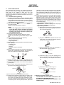
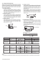
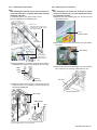
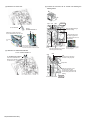
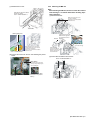
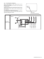
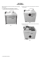
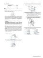
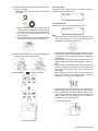
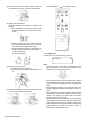
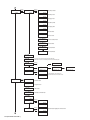
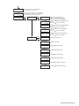
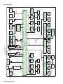
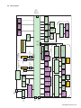
Datacard® SR200/SR300
Printer
Service Manual
April 2010
Part No. 539898-001, Rev A
Proprietary Notice
All information herein is the property of DataCard Corporation. All
unauthorized use and reproduction is prohibited.
Trademark Acknowledgments
Datacard is a registered trademark and service mark of DataCard Corporation in
the United States and other countries.
All other product names are the property of their respective owners.
Revision Log
SR200/SR300 Service Manual
Revision
Date
A
April 2010
Description of Changes
First release of this document.
Datacard Group
11111 Bren Road West
Minnetonka, MN 55343-9015
952.933.1223
Fax: 952.933.7971
www.datacard.com
© 2010 DataCard Corporation. All rights reserved.
Printed in the United States of America.
SPECIFICATION
SR200, SR300
Specifications
Recording system
Dye sublimation retransfer
Paper feed mode
Automatic
Recording density
300 dpi
Reproduction gradation
256 levels each for Y, M and C; C and 2 for Bk
Interface
USB 2.0 (Hi-Speed/Full-Speed)
Operating environment conditions
Temperature: 15°C to 30°C
Temperature: 17°C to 28°C (When peel off, UV ink is used)
Operating environment conditions
Humidity: 35% to 70 %
Humidity: 35 % to 60 % (When peel off, UV ink is used)
Storage environment conditions
Temperature: -15°C to 55°C
Storage environment conditions
Humidity: 20 % to 80 %
Power supply
AC 100V - 120V, AC 220V - 240V (allowance ±10%) 50/60Hz (allowance ±5%)
Current consumption
3.5 A (100 V system), 1.6A (200V system)
Power consumption
310 W (max.)
Mass
Standard approx. 12.5 kg (excluding optional built-in items)
Dimensions
343 mm x 335 mm x 322 mm (W x H x D)
Ethernet (100BASE-TX/10BASE-T)
Accessories
Quick Reference× 1, Read Me First× 1, Power Cord (2 m)× 2, Cleaning Card× 1, Card Stacker× 1, USB 2.0 Cable:QAM1196(2 m)×
1, Gloves× 1, Tweezers× 1
Products sold separately: Ink
Ribbon/Retransfer Film
To purchase these items, consult our authorized dealers.
Ink Ribbon (YMCK), 1,000 frames/roll Model
CY-340-100R
Ink Ribbon (YMCKK), 750 frames/roll Model
CY-35K-75R
Ink Ribbon (YMCKP), 750 frames/roll Model
CY-35P-75R
Ink Ribbon (YMCKU), 750 frames/roll Model
CY-35U-75R
Retransfer Film (YMCKK), 1,000 frames/roll Model CY-3RA-100R(B)
Cleaning Kit
Magnetic Head Cleaning Card (5 pcs), Cotton Swab (5 Large and 5 small),
Cleaning Wipes (1 Box, Model: CX210-CKIT1)
Cleaning Card
10 pcs/Set (Model: CX210-CC1)
1-2 (No.HD007<Rev.001>)
SECTION 1
PRECAUTION
1.1 SAFETY PRECAUTIONS
Prior to shipment from the factory, JVC products are strictly inspected to conform with the recognized product safety and electrical codes of the countries in which they are to be
sold.However,in order to maintain such compliance, it is equally
important to implement the following precautions when a set is
being serviced.
1.1.1 Precautions during Servicing
(1) Locations requiring special caution are denoted by labels
and inscriptions on the cabinet, chassis and certain parts of
the product.When performing service, be sure to read and
comply with these and other cautionary notices appearing
in the operation and service manuals.
(2) Parts identified by the symbol and shaded (
) parts
are critical for safety.
Replace only with specified part numbers.
NOTE :
Parts in this category also include those specified to
comply with X-ray emission standards for products
using cathode ray tubes and those specified for
compliance with various regulations regarding spurious radiation emission.
(3) Fuse replacement caution notice.
Caution for continued protection against fire hazard.
Replace only with same type and rated fuse(s) as specified.
(4) Use specified internal wiring. Note especially:
• Wires covered with PVC tubing
• Double insulated wires
• High voltage leads
(5) Use specified insulating materials for hazardous live parts.
Note especially:
• Insulation Tape
• PVC tubing
• Spacers
• Insulation sheets for transistors
• Barrier
(6) When replacing AC primary side components (transformers,
power cords, noise blocking capacitors, etc.) wrap ends of
wires securely about the terminals before soldering.
cathode ray tubes and other parts with only the specified
parts. Under no circumstances attempt to modify these circuits.Unauthorized modification can increase the high voltage value and cause X-ray emission from the cathode ray
tube.
(12) Crimp type wire connector In such cases as when replacing the power transformer in sets where the connections
between the power cord and power trans former primary
lead wires are performed using crimp type connectors, if
replacing the connectors is unavoidable, in order to prevent
safety hazards, perform carefully and precisely according
to the following steps.
• Connector part number :E03830-001
• Required tool : Connector crimping tool of the proper
type which will not damage insulated parts.
• Replacement procedure
a) Remove the old connector by cutting the wires at a
point close to the connector.Important : Do not reuse a connector (discard it).
cut close to connector
Fig.1-1-3
b) Strip about 15 mm of the insulation from the ends
of the wires. If the wires are stranded, twist the
strands to avoid frayed conductors.
15 mm
Fig.1-1-4
c) Align the lengths of the wires to be connected. Insert the wires fully into the connector.
Metal sleeve
Connector
Fig.1-1-1
(7) Observe that wires do not contact heat producing parts
(heatsinks, oxide metal film resistors, fusible resistors, etc.)
(8) Check that replaced wires do not contact sharp edged or
pointed parts.
(9) When a power cord has been replaced, check that 10-15
kg of force in any direction will not loosen it.
Power cord
Fig.1-1-5
d) As shown in Fig.1-1-6, use the crimping tool to
crimp the metal sleeve at the center position. Be
sure to crimp fully to the complete closure of the
tool.
1.2
5
2.0
5.5
Crimping tool
Fig.1-1-6
e) Check the four points noted in Fig.1-1-7.
Not easily pulled free
Crimped at approx. center
of metal sleeve
Conductors extended
Fig.1-1-2
(10) Also check areas surrounding repaired locations.
(11) Products using cathode ray tubes (CRTs) In regard to such
products, the cathode ray tubes themselves, the high voltage circuits, and related circuits are specified for compliance with recognized codes pertaining to X-ray emission.
Consequently, when servicing these products, replace the
Wire insulation recessed
more than 4 mm
Fig.1-1-7
(13) Battery replacement caution notice.
CAUTION RISK OF EXPLOSION IF BATTERY IS REPLACED BY AN INCORRECTIVE TYPE.
DISPOSE OF USED BATTERIES ACCORDING TO THE
INSTRUCTIONS.
(No.HD007<Rev.001>)1-3
1.1.2 Safety Check after Servicing
Examine the area surrounding the repaired location for damage
or deterioration. Observe that screws, parts and wires have been
returned to original positions, Afterwards, perform the following
tests and confirm the specified values in order to verify compliance with safety standards.
(1) Insulation resistance test
Confirm the specified insulation resistance or greater between power cord plug prongs and externally exposed
parts of the set (RF terminals, antenna terminals, video and
audio input and output terminals, microphone jacks, earphone jacks, etc.).See table 1 below.
(2) Dielectric strength test
Confirm specified dielectric strength or greater between
power cord plug prongs and exposed accessible parts of
the set (RF terminals, antenna terminals, video and audio
input and output terminals, microphone jacks, earphone
jacks, etc.). See Fig.1-1-11 below.
(3) Clearance distance
When replacing primary circuit components, confirm specified clearance distance (d), (d') between soldered terminals, and between terminals and surrounding metallic
parts. See Fig.1-1-11 below.
(4) Leakage current test
Confirm specified or lower leakage current between earth
ground/power cord plug prongs and externally exposed accessible parts (RF terminals, antenna terminals, video and
audio input and output terminals, microphone jacks, earphone jacks, etc.).
Measuring Method : (Power ON) Insert load Z between
earth ground/power cord plug prongs and externally exposed accessible parts. Use an AC voltmeter to measure
across both terminals of load Z. See Fig.1-1-9 and following Fig.1-1-12.
a
Externally
exposed
accessible part
Z
A
b
c
V
Fig.1-1-9
(5) Grounding (Class 1 model only)
Confirm specified or lower grounding impedance between
earth pin in AC inlet and externally exposed accessible
parts (Video in, Video out, Audio in, Audio out or Fixing
screw etc.).Measuring Method:
Connect milli ohm meter between earth pin in AC inlet and
exposed accessible parts. See Fig.1-1-10 and grounding
specifications.
d
d'
Chassis
Power cord
primary wire
Exposed accessible part
AC inlet
Fig.1-1-8
Earth pin
MIlli ohm meter
Grounding Specifications
Region
Grounding Impedance ( Z )
USA & Canada
Z
0.1 ohm
Europe & Australia
Z
0.5 ohm
Fig.1-1-10
AC Line Voltage
100 V
100 to 240 V
Region
Insulation Resistance (R)
Japan
110 to 130 V
USA & Canada
110 to 130 V
200 to 240 V
Europe & Australia
R
1M
1 M /500 V DC
R
R
12 M /500 V DC
10 M /500 V DC
Dielectric Strength
AC 1 kV 1 minute
AC 1.5 kV 1 minute
Clearance Distance (d), (d')
d, d '
3 mm
d, d '
4 mm
AC 1 kV 1 minute
AC 3 kV 1 minute
(Class )
AC 1.5 kV 1 minute
(Class )
d, d'
3.2 mm
d
4 mm
d'
8 m m (Power cord)
d'
6 m m (Primary wire)
Leakage Current (i)
a, b, c
Fig.1-1-11
AC Line Voltage
100 V
Japan
110 to 130 V
USA & Canada
110 to 130 V
220 to 240 V
Load Z
Region
Europe & Australia
i
1 mA rms
Exposed accessible parts
i
0.5 mA rms
Exposed accessible parts
2
i
i
0.7 mA peak
2 mA dc
Antenna earth terminals
50
i
i
0.7 mA peak
2 mA dc
Other terminals
1
0.15
1.5
Fig.1-1-12
NOTE :
These tables are unofficial and for reference only. Be sure to confirm the precise values for your particular country and locality.
1-4 (No.HD007<Rev.001>)
SECTION 2
SPECIFIC SERVICE INSTRUCTIONS
2.1
Name and functions of parts
2.1.1 Exterior
Card hopper
Operation panel
and buttoms
Space for input
output connectors
Card exit
Host
interface
Card stacker
Security slot
Printer door
AC Inlet
Cooling fan
NG Card exit
Communication port
for laminator
Power switch
2.1.2 Internal mechanism
Retransfer
heat roller Card convey
section
Contactless IC encoder install space
Magnetic encoder unit
Bend remedy
heat roller
Card hopper
Cleaning roller
Card stacker
Card convey unit for single
sided or dual sided
IC Contact
Ink ribbon
Ink cassette
JOG Dial
Re-Transfer
film cassette
RFID Antenna
JOG Dial
Retransfer film
Thermal head
(No.HD007<Rev.001>)1-5
2.2
ATTACHING THE SEPARATELY SOLD PARTS
2.2.1 Preparation
Before connecting the separately sold parts, remove the top cover and the rear cover to pull open the MAIN Board.
(1) Remove the two screws attaching from the rear side of the
main unit.
Screw:
QYSDSP4012NA x 2
Rear cover
(4) Disconnect the wire connected to the MAIN Board.
Release the wires from the wire clamp.
Disconnect the connector from the turn unit.
(Only the models with turn unit)
(5) Remove the four screws attaching the brackets that fix the
MAIN Board.
Screw : QYSDST3006 x 4
(2) Remove the top cover by sliding it to the direction of the arrow.
2
1
Top cover
Slide the top cover to
the rear side about
10 mm, and then pull
it up.
MAIN Board
(6) Pull open the MAIN Board, and hook the two brackets at
the bottom of the MAIN Board to the frame of the main unit.
(3) Remove the rear cover by pulling it open to the rear side.
1) Swing open the upper part to
the rear side on the axis of the
lower part.
2) Slide the rear cover downwards
to release the hook.
3) Pull the rear cover to the rear side
to remove.
1
Rear cover
3
2
1-6 (No.HD007<Rev.001>)
• Be careful not to catch wires in between.
2.2.2 Attaching the reform H unit
2.2.3 Attaching the IC contact unit
Note:
After mounting the reform H unit, be sure to check the relevant item referring to "2.3 Check details after mounting
separately sold parts".
(1) Insert the reform H unit, and fix it with a screw.
(2) Fix the bracket with an attaching screw.
Note:
After mounting the IC contact unit, be sure to check the
relevant item referring to "2.3 Check details after mounting separately sold parts".
(1) Remove the screw attaching the turn unit from the front
side of the main unit.
Reform H unit
* When attaching the reform H unit,
be careful not to damage the heat
roller with the bracket.
Screw :
QYSDST3006NA
Bracket
Screw :
QYSDST3006NA
(2) Remove the wires, which come from the turn unit, from the
wire clamp.
Wire clamp
Screw :
QYSDST3006NA
Insert the tip of the
shaft into the front
plate.
(3) Remove the dummy connector connected to the CN3 on
the MAIN Board. (Only when attaching the reform H unit)
(3) Remove the three screws attaching the turn unit, and then
pull out the turn unit. (Only the models with turn unit)
MAIN
Board
CN3
Dummy
connector
Turn unit
(4) Guide the wires from the reform H unit through the wire
clamps as shown in the drawing, and then connect the
wires to the MAIN Board.
Screw :
QYSDST3006NA x 3
Wire clamp
MAIN Board
CN2
CN3
As the reform H unit moves up and down during operation,
be sure to allow about 1 to 2 cm wire slack.
(No.HD007<Rev.001>)1-7
(4) Mount the IC contact unit.
(6) Connect the wire from the IC contact unit following the
drawing below.
B
A
CN4
CN1
CN3
View A
IC Contact unit
Run the wires through
this wire clamp.
Screw :
QYSDST2604NA x 2
Slide the IC contact unit into the
hook of the bracket on the main unit.
Fix the wires with the two
wire clamps. (Tighten the
wire clampsas shown in the
picture below.)
Hook
IC Contact
unit
Align the screw holes, make sure that
the IC contact unit does not move, and
then fix the IC contact unit with the screws.
IC CONTACTIFC
Board
Run the wires from the IC contact
unit through this wire clamp.
(5) Attach the IC CONTACTIFC Board.
Screw : QYSDST3006NA x 2
CN4
Be careful to prevent wires from
touching nearby rotating objects
such as belts/gears.
CN3
IC CONTACTIFC Board
Insert the IC CONTACTIFC
Board into the bracket
on the main unit.
CN2
Connect the free PH10-pin
connector of the jump wire.
Jump wire
Fold back, and then run the
excess of the wire (red),
connected to the CN4, through
the wire clamp as shown in the
drawing.
IC CONTACTIFC Board
1-8 (No.HD007<Rev.001>)
View B
(7) Reattach the turn unit.
2.2.4 Attaching the MG unit
Note:
After mounting the MG unit, be sure to check the relevant
item referring to "2.3 Check details after mounting separately sold parts".
(1) Mount the MG unit.
After attaching this screw, attach
another two screws.
Screw : QYSDST3006NA x 3
Make sure that the wires do not
run over the brackets.
If the wires run over the brackets,
release the wires.
Turn unit
Bearing fitting hole
MG Unit
Align the front end of the
MG unit to the grooves
(a) and (b) of the front
bracket.
(a)
(b)
(a)
(b) Attention of there is
groove also under (a).
Screw : QYSDST3006NA
Make sure that the turn unit bearing
securely fits the hole on the main unit,
and the screw holes align.
Push the turn unit from the rear side to
attach the screw.
(8) Connect the wires from the turn unit following the picture
below.
(c)
While aligning the
grooves of the MG unit
bracket and the main unit
bracket, lower the back
end of the MG unit.
(c)
(2) Fix the MG unit with the three screws.
Screw : QYSDST3006NA x 3
Wire clamp
Be careful to prevent wires from
touching nearby rotating objects
such as belts/gears.
Turn unit
CN1
(Tighten the wire clamp
as shown in the picture
above.)
MG Unit
(No.HD007<Rev.001>)1-9
(3) Close back the MAIN Board to its original position, and fix
the MAIN Board with the four screws.
Securely hook the two brackets, fixing the
MAIN Board, to the frame of the main unit.
(4) Connect the wires from the MG unit and the turn unit following the drawing below.
Connect the MG unit and the board bracket, and fix them with screws.
Wire : QUB030-05HMHM-E
Screw : QYSDST3006NA x 2
Wire from the turn unit CN1
Run the wires from the turn
unit and the MG unit together
through this wire clamp, and
fix them.
MG UNIT
CN19
CN15
MAIN Board
Coaxial connector
Make sure that the coaxial
connector is not loose.
Screw :
QYSDST3006NA x 4
MAIN Board
MG Unit
MG unit accessories
Allow about 5 mm slack to
enable the cable to move.
Wire from the
turn unit CN1
A
Wire clamp
B
MAIN Board
View A
The cam gear and the wire should be parted.
CN15 CN19
2.2.5 Attaching the IC R/W unit
Note:
After mounting the IC R/W unit, be sure to check the relevant item referring to "2.3 Check details after mounting
separately sold parts".
(1) Attach the IC R/W unit to the plate.
QYSPSPH3006NA x 3
IC R/W Unit
Organize the head wire so that it does not
touch the rotating parts such as belts/gears,
and then fix the head wire with the wire clamp.
Make sure that the wires do not touch the encoder.
View B
Opened MAIN Board
1-10 (No.HD007<Rev.001>)
QZW0326-002 x 3
(2) Mount the IC R/W unit.
Run the earth wire under
the wires from the FRONT Board.
QYSDSF3008NA x 2
IC R/W Unit
QYSDST3006NA
QUB340-07DMDM-E
(3) Connect the wires from the IC R/W unit following the drawing below.
Connect the supplied USB cable
and the connector J1 on the MAIN Board.
Wire clamp
IC R/W Unit
Connect the supplied wire (10-pin)
to the connector CN5 on the
IC CONTACTIFC Board.
Wire clamp
CN5
J1
2.2.6 Attaching the top cover and the rear cover
(1) Attach the top cover and the rear cover in the reverser procedure of disassembly.
(No.HD007<Rev.001>)1-11
2.3
Check details after mounting separately sold parts
Item
Check details
Required tools
1
Reform H unit
The warpage of the printed card should be within the specs (1.5 Blank card
mm).
2
IC Contact unit
Check the IC contact position mark using a blank card and a Blank card, Contact label
contact label.
• Service mode > Offline Test > Test the IC (Contact).
• If the position is out of specs, Maintenance > OffsetContact to
adjust the position. (See 2.3.1 IC contact position adjustment)
The card written with an application should be read by the read- Contact IC card
er.
Contact IC reader
(Check in the USB and Ethernet connections)
3
MG Unit
Service mode > Offline Test > test the MG.
• The test should be finished normally.
MG card
The card written with an application should be read by the read- MG reader
er.
• There is no adjustment for an MG unit after mounting because
MG units are shipped after being position adjusted. Check for
normal operation only.
4
Running after mounting the Test for normal printing on about 10 cards
separately sold parts
• Service mode > Offline Test > print
(For all separately sold parts)
Item
5
Item
Safety test (for Withstand
all separately voltage test
sold parts)
Insulation resistance test
Evaluation card
Conditions & specs
Timer
Leak current
Test voltage
2 to 3 sec.
10mA
AC1600±50V
Test point
Test voltage
Insulation resistance value
DC 500V
100MΩ and over
Grounding
Timer
continuity test 3 to 4 sec.
Test current
Spec value
AC25A
0.1Ω or under
(Without power cord)
(With the POWER SW: ON)
Screw A on the top left of the
rear panel in the drawing below
|
GND C on the AC inlet in the
drawing below
A
C
B
1-12 (No.HD007<Rev.001>)
(With the POWER SW: ON)
GND C on the AC inlet in the
drawing below
|
Bipolar B on the power cord in
the drawing below
2.3.1 IC contact position adjustment
Apply a contact label (part number: KXL46372-001) on the IC
chip of a contact IC card.
Select the IC contact test from “off line test” in the service mode
to perform the test.
After the test, measure the IC contact position mark on the contact label using a vernier caliper to check if the position stays
within the specs.
If the position does not stay within the specs, correct the position
in the “OffsetContact” mode in the service mode.
When the position is corrected, turn off the power and turn it on
again before testing the IC contact.
Contact label
(part number:KXL46372-001)
(Specs)
direction
c
IC contact
position specs
d
e
f
direction
a
b
a : 10.25 ~ 12.25 mm
b : 17.87 ~ 19.87 mm
c : 19.23 ~ 20.93 mm
d : 21.77 ~ 23.47 mm
e : 24.31 ~ 26.01 mm
f : 26.85 ~ 28.55 mm
(No.HD007<Rev.001>)1-13
SECTION 3
DISASSEMBLY
Before disassembly, be sure to turn OFF the power and unplug
the power cord.
3.1
(2) Slide the top cover unit to the rear side, then remove the
top cover unit.
Removing the covers (See figure 1 to figure 4)
Top cover unit
(1) Remove the two screws A attaching the top cover unit.
Top cover unit
Fig.2
A
A
Fig.1
(3) Pull the rear cover unit open to the rear side, then remove
the rear cover unit.
Rear cover unit
Fig.3
1-14 (No.HD007<Rev.001>)
(4) Remove the two screws C attaching the side cover U-R
and side cover U-L, then remove the side cover U-R and
side cover U-L.
(2) Remove the two screws D attaching the cover, then remove the cover.
C
C
Side cover U-L
Side cover U-R
D
Fig.4
3.2
Removing the front panel unit (See figure 5 to figure
12)
(1) Remove the Media F CA unit, the Ink F CA unit, and the CL
Roller unit.
Cover
Fig.6
Head unit
(3) Remove the four screws E attaching the front panel unit.
• Be careful not to break the cable.
E
Front panel unit
E
CL Roller unit
E
Media F CA unit
Cable
Fig.7
E
Ink F CA unit
Fig.5
(No.HD007<Rev.001>)1-15
(4) Disconnect the two cables from the connectors on the front
board.
(7) Front panel unit with the cover removed.
Cover
Front panel unit
Connectors
Fig.8
(5) Remove the one screw F attaching the cover.
(6) Press the two tabs, pull up the cover at the point marked
with an arrow, and then remove the cover.
Fig.10
(8) Disconnecting the cable from the RFID1 board detaches
the front panel unit from the main unit.
Cable
F
Tab Tab
RFID1 board
Fig.11
(9) Main unit with the front panel unit removed.
Cover
Fig.9
Fig.12
1-16 (No.HD007<Rev.001>)
3.3
Removing the major boards and major units (See figure 13 to figure 33)
(4) Hanging the left and right brackets on the main board to the
hooks on the chassis prevents the main board from falling.
(1) Disconnect the four cables from the connectors on the
main board.
(2) Remove the four screws G attaching the main board.
G
Connectors
Hook
G
Fig.15
Hook
G
Main board
Fig.13
G
(3) Pull the main board open to the rear side.
Fig.16
Main board
Fig.14
(5) Remove the three screws H attaching the CF-7MGS UNIT,
then remove the CF-7MGS UNIT.
H
H
CF-7MGS UNIT
Fig.17
(No.HD007<Rev.001>)1-17
(6) Removed CF-7MGS UNIT.
(9) Remove the four screws K to release the SECURITY PWB
ASSY and the solenoid on the front side.
K
Fig.18
(7) The KEY LOCK UNIT consists of a SECURITY PWB ASSY
and two solenoids.
Solenoid SECURITY PWB ASSY
K
Solenoid
SECURITY PWB ASSY
Fig.21
(10) Removed KEY LOCK UNIT SET.(LS31237-201A)
Solenoid
Fig.19
(8) Remove the one screw J to release the solenoid on the
card stocker side.
J
Fig.22
(11) Remove the two screws L attaching the IC R/W UNIT, then
remove the IC R/W UNIT.
L
Solenoid
Fig.20
IC R/W UNIT
(CF-7CRW)
Fig.23
1-18 (No.HD007<Rev.001>)
L
(12) Removed IC R/W UNIT.
(14) Remove the two screws N attaching the cover, then remove the cover.
N
Fig.24
(13) Remove the one screw M attaching the CONTACTIFC
board, then slide the CONTACTIFC board forward to remove.
Cover
Fig.27
N
(15) Before removing the IC CON UNIT, the turn unit needs to
be removed first.
CONTACTIFC board
IC CON UNIT
Fig.28
M
Fig.25
• To attach the CONTACTIFC board, insert the part a into
the slit on the front side.
Part a
Fig.26
(No.HD007<Rev.001>)1-19
(16) Remove the four screws P attaching the turn unit from the
front side and the rear side.
(18) Remove the two screws Q attaching the IC CON UNIT section, then remove the IC CON UNIT section.
IC CON UNIT section
Turn unit
P
Fig.29
P
Turn unit
P
Fig.30
(17) Removed turn unit.(CF-7FU)
Fig.31
1-20 (No.HD007<Rev.001>)
Q
Fig.32
P
(19) Removed CONTACTIFC board and IC CON UNIT.
JIS : CF-7CCJ
ISO: CF-7CCS
IC CON UNIT
Fig.33
3.4
Replacing the head unit (See figure 34 and figure 35)
3.5
(1) Remove the one screw R attaching the head unit.
Removing the reform H unit (See figure 36 and figure
37)
(1) Remove the one screw S attaching the reform H unit, then
pull out the reform H unit.
(2) To replace the heater only, remove the one screw T.
R
S
T
Head unit
Fig.34
Fig.36
(3) Removed reform H unit.
(2) Pull out the head unit paying attention to the cable, then
disconnect the two connectors.
Heater
Fig.37
Connectors
Note:
* Do not cut the cable lock. This cable lock is removable.
* Press to loosen the lock in the direction of the arrow.
The cable lock can be removed.
3.6
Replacing the heater on the heat rol unit (See figure 38
and figure 39)
(1) Remove the one screw U attaching the cover from the front
side.
Fig.35
U
Fig.38
(No.HD007<Rev.001>)1-21
(3) Remove the five screws V attaching the motor base unit,
then remove the motor base unit.
(2) Pulled out heater.
V
V
Heater
Fig.39
3.7
Removing the motor base unit (See figure 40 to figure
43)
Motor base unit
Fig.42
(4) Main unit with the motor base unit removed.
(1) Push two tabs on the PS cover, then remove the PS cover.
PS cover
Fig.40
(2) Main unit with the PS cover removed
Cable for head unit
Motor base unit
Power supply unit
Fig.41
1-22 (No.HD007<Rev.001>)
When the gear is detached, the position of a triangular
sign and a round sign is matched and installed.
Fig.43
SECTION 4
ADJUSTMENT
This service manual does not describe ADJUSTMENT.
SECTION 5
TROUBLE SHOOTING
5.1
When an error message is display
(2) Lift to remove the card hopper cover.
When the error occurs, the error message and the error code are
displayed in the operation panel.
Solve the error referring to the following when the error occurs.
XXXXXXXXX
XX
Error message
Error code
5.1.1 No Card
Cards have run out. Replenish the cards. Or, The card hopper is
not attached. Attach the card hopper.
No Card
Note:
• Do not touch the printing surface of the card. Touching it
may cause printing errors. Put on the supplied gloves when
handling the cards.
• When using new cards, separate them one by one before
setting them in the printer. Cards may be adhered to each
other due to static, thus causing card jams.
• Align the cards before setting them in the printer. Otherwise,
the card hopper cover may not close properly, and this may
damage the printer.
• Printing the card on the side with the magnetic stripe may
cause printing errors or damage to the card's functions. If
you want to do so, consult our authorized dealers in advance.
• To set cards with both functions (magnetic stripe and contact
IC), follow the procedure for setting the contact IC card.
(1) Set the card hopper knob to [OPEN].
(3) Align the orientation of the cards, and set them in the
printer.
[Magnetic cards]
Set the card with the magnetic stripe facing upward and
toward the printer, or facing downward and toward you.
[JIS contact IC cards]
Set the card with the Contact IC terminal facing upward
and toward the front of the printer, or downward and toward the front of the printer.
[ISO contact IC cards]
Set the card with the Contact IC terminal facing upward
and toward the rear of the printer, or downward and toward the rear of the printer.
(4) Install the card hopper cover.
(No.HD007<Rev.001>)1-23
5.1.2 Jam (Hopper)
Card jam in the card hopper unit. Remove the jammed card.
Jam (Hopper)
c) Close the printer door, and press [RESET] →
initialize the printer.
to
90
Note:
• Do not apply excessive force on the card hopper. Doing so
may damage it.
• Do not touch the printing surface of the card. Touching it
may cause printing errors. Put on the supplied gloves when
handling the cards.
(1) Remove the card hopper.
(2) Remove the loaded cards, and pull out the jammed card
with a hand.
5.1.3 Jam (Turn Over)
Card jam in the turnover unit. Remove the jammed card.
Jam (Turn Over)
91
(3) Install the card hopper cover.
[If the card cannot be pulled out by hand]
a) Open the printer door.
b) The retransfer part and the cleaning unit are rotated
in the direction of clockwise by using the jog dial.
(1) Remove the card hopper.
(2) Open the printer door, and then remove the cleaning unit.
[If the cleaning unit cannot be removed]
a) The cleaning unit is rotated in the direction of clockwise by using the jog dial.
1-24 (No.HD007<Rev.001>)
b) The cover of the card hopper is opened. When the
card can be removed, it removes.
5.1.4 Jam (MG)
Card jam in the magnetic encoder unit. Remove the jammed
card.
Jam (MG)
92
(1) Open the printer door.
(3) The turnover part is rotated a little right and left by using the
jog dial.
Note:
When the card has gone out of the turnover part, the
turnover part cannot be rotated.
The turnover part and the cleaning unit are rotated in a
right and left, opposite direction at the same time, and
the card is moved to the turnover part.
(2) Restore the card to the magnetic encoder unit.
Use the jog dial to turn the cleaning unit.
(3) Turn the jog dial at the turnover unit to adjust the unit to a
vertical position.
While doing so, make use of the printer's label as a reference.
(4) Move the card to the center of the turnover unit
• Maintain the turnover unit in the vertical position.
• Turn the jog dial at the cleaning unit.
Check to ensure that the card moves to the turnover unit.
(5) Turn the jog dial attached to the turnover and cleaning units
at the same time in opposite directions.
• Set the turnover unit to the horizontal position.
(6) Turn the jog dial of the turnover unit clockwise to an angle
of 45 degrees.
• While doing so, make use of the printer's label as a reference.
(7) Turn the jog dial at the cleaning unit in the anti-clockwise
direction.
• The card is discharged from the NG card outlet.
(4) The turnover part and the cleaning unit are rotated in a right
and left, opposite direction at the same time, and the card
is moved to the turnover part.
(5) Close the printer door, and press [RESET] →
to initialize the printer.
• The card is discharged from the NG card outlet or card
stacker.
(No.HD007<Rev.001>)1-25
(8) Press [RESET] →
to initialize the printer.
(2) The retransfer film cassette (left side) is taken out, and the
inside of the printer is confirmed.
(3) When the card sticks on the retransfer film, the card is removed.
(4) Close the printer door, and press [RESET] →
tialize the printer.
5.1.5 Jam (Transfer)
Card jam in the transfer unit. Remove the jammed card.
Jam (Transfer)
93
(1) Press [RESET] →
to initialize the printer.
• The card is discharged from the NG card outlet or card
stacker.
5.1.6 Jam (Discharge)
Card jam in the discharge unit. Remove the jammed card.
Jam (Discharge)
(1) Open the printer door.
1-26 (No.HD007<Rev.001>)
94
to ini-
5.1.7 Film Serch
Retransfer film is broken. Repair it.
Film Serch
(3) Cut away the broken portion, and attach the unused portion at the supply side to the other end at the take-up side
using an adhesive tape.
A1
Note:
• Stand the cassette on a flat surface as illustrated in the diagram.
Avoid doing so on a floor as dust attached to the retransfer
film may cause printing errors.
• Do not touch the inked surface (the side that faces outward
when installed) with your hand. Touching it may cause printing errors. Put on the supplied gloves when handling the
retransfer film.
• When handling the cassette, hold it with both hands.
Accidentally dropping the cassette may damage it or result
in injuries.
• When installing a used retransfer film, align the unused side
of the film with the arrow indicated on the label of the cassette.
Failure to do so may result in errors, or the print may turn out
light.
• Do not perform work on the printer door. Do not place heavy
objects or apply load on the printer. Doing so may damage it.
• During replacement, clean the four bobbin holders on the
printer.
Burrs generated by friction between the bobbins and bobbin
holders may be adhered to the ink ribbon or retransfer film,
causing printing errors.
(4) Attach the retransfer film, and turn the take-up side until
the cut section is out of sight.
a) With the retransfer face facing outward, align the
unused side of the film with the arrow on the cassette, and unwind it along the three shafts.
b) Insert the retransfer film firmly into the bobbin holders with the film set to the far end of the guides.
c) Turn the knob in the direction of the arrow to remove any slack.
(5) Insert the cassette all the way in along the guide rail until
a "click" sound is heard. Close the door.
(1) Open the printer door.
(2) Press and hold down the cassette button, and pull out
the cassette (on the left) to remove the retransfer film.
(No.HD007<Rev.001>)1-27
(6) Press [RESET] →
to initialize the printer.
5.1.10 Ink Serch
Ink ribbon is broken. Repair it.
Ink Serch
B1
Note:
• Stand the cassette on a flat surface as illustrated in the diagram.
Avoid doing so on a floor as dust attached to the ink ribbon
may cause printing errors.
5.1.8 MG Test Err
MG writing error occurred during MG self-diagnosis.
Reset the printer.
MG Test Err
A8
5.1.9 Ink Error
An incorrect printer ink is installed. Attach a correct ink.
Ink Error
• Do not touch the inked surface (the side that faces outward
when installed) with your hand. Touching it may cause printing errors. Put on the supplied gloves when handling the ink
ribbon.
• When handling the cassette, hold it with both hands.
Accidentally dropping the cassette may damage it or result
in injuries.
• When installing a used ink ribbon, align the yellow side of the
unused ribbon with the arrow indicated on the label of the
cassette.
If the position of the yellow side is not properly aligned, the
print may turn out light.
• Do not perform work on the printer door. Do not place heavy
objects or apply load on the printer. Doing so may damage it.
• During replacement, clean the four bobbin holders on the
printer.
Burrs generated by friction between the bobbins and bobbin
holders may be adhered to the ink ribbon or retransfer film,
causing printing errors.
(1) Open the printer door.
B0
(2) Press and hold down the cassette button, and pull out
the cassette (on the right) to remove the ink ribbon.
(3) Cut away the broken portion, and attach the unused portion at the supply side to the other end at the take-up side
using an adhesive tape.
1-28 (No.HD007<Rev.001>)
(4) Set the ink ribbon, and turn the take-up side until the cut
section is out of sight.
• Install while referring to the indication on the label of
the cassette.
5.1.11 Door Open
Printer door is open. Close the door. Or, the cleaning roller is not
attached. Attach the cleaning roller.
Door Open
D1
5.1.12 Film Run Out
Retransfer film has run out. Replace with a new one.
a) With the inked surface facing outward, align the
yellow side of the unused ribbon with the arrow on
the cassette, and unwind it along the three shafts.
b) Turn the knob in the direction of the arrow to remove any slack.
c) Insert the ink ribbon firmly into the bobbin holders
with the ribbon set to the far end of the guides.
(5) Insert the cassette all the way in along the guide rail until
a "click" sound is heard. Close the door.
(6) Press [RESET] →
to initialize the printer.
Film Run Out
A2
Note:
• Stand the cassette on a flat surface as illustrated in the diagram. Avoid doing so on a floor as dust attached to the
retransfer film may cause printing errors.
• Do not touch the retransfer face (the side that faces outward
when installed) with your hand. Touching it may cause printing errors. Put on the supplied gloves when handling the
retransfer film.
• When handling the cassette, hold it with both hands. Accidentally dropping the cassette may damage it or result in injuries.
• When installing a used retransfer film, align the unused side
of the film with the arrow indicated on the label of the cassette. Failure to do so may result in errors, or the print may
turn out light.
• When installing a new film, make sure that at least three
black lines are wound onto the take-up side. Insufficient
winding may cause the printer to malfunction.
• Do not perform work on the printer door. Do not place heavy
objects or apply load on the printer. Doing so may damage it.
• During replacement, clean the four bobbin holders on the
printer. Burrs generated by friction between the bobbins and
bobbin holders may be adhered to the ink ribbon or
retransfer film, causing printing errors.
(1) Open the printer door.
(No.HD007<Rev.001>)1-29
(2) Press and hold down the cassette button, and pull out
the cassette (on the left) to remove the retransfer film.
(6) Press [RESET] →
to initialize the printer.
(3) Install a new retransfer film.
Install while referring to the indication on the label of the
cassette.
a) When installing the retransfer film, make sure that
at least three black lines are wound onto the takeup side.
b) With the retransfer face facing outward, align the
unused side of the film with the arrow on the cassette, and unwind it along the three shafts.
c) Insert the retransfer film firmly into the bobbin holders with the film set to the far end of the guides.
A: take-up side (black)
B: unused side (green)
5.1.13 Ink Run Out
Ink ribbon has run out. Replace with a new one.
Ink Run Out
(4) Remove any slack in the film.
a) Hold the retransfer film cassette.
b) Turn the knob in the direction indicated by the arrow.
(5) Insert the cassette all the way in along the guide rail until
a "click" sound is heard. Close the door.
1-30 (No.HD007<Rev.001>)
B2
Note:
• Stand the cassette on a flat surface as illustrated in the diagram. Avoid doing so on a floor as dust attached to the
retransfer film may cause printing errors.
• Do not touch the inked surface (the side that faces outward
when installed) with your hand. Touching it may cause printing errors. Put on the supplied gloves when handling the ink
ribbon.
• When handling the cassette, hold it with both hands. Accidentally dropping the cassette may damage it or result in injuries.
• When installing a used ink ribbon, align the yellow side of the
unused ribbon with the arrow indicated on the label of the
cassette. If the position of the yellow side is not properly
aligned, the print may turn out light.
• Do not perform work on the printer door. Do not place heavy
objects or apply load on the printer. Doing so may damage it.
• During replacement, clean the four bobbin holders on the
printer. Burrs generated by friction between the bobbins and
bobbin holders may be adhered to the ink ribbon or
retransfer film, causing printing errors.
(1) Open the printer door.
(6) Press [RESET] →
to initialize the printer.
(2) Press and hold down the cassette button, and pull out the
cassette (on the right) to remove the ink ribbon.
(3) Install a new ink ribbon.
Install while referring to the indication on the label of the
cassette.
a) With the inked surface facing outward, align the yellow side of the unused ribbon with the arrow on the
cassette, and unwind it along the three shafts.
b) Insert the ink ribbon firmly into the bobbin holders
with the ribbon set to the far end of the guides.
A: take-up side (black)
B: unused side (yellow)
5.1.14 Hard ware
A hardware failure has occurred on the printer. Turn off and on
the power. If the same problem recurs, turn off the power and
consult our authorized dealers.
Hard ware
5.1.15 MG Mechanical
An error has occurred in the mechanical component of the MG
unit. Turn off and on the power. If the same problem recurs, turn
off the power and consult our authorized dealers.
MG Mechanical
(4) Remove any slack in the ink ribbon.
a) Hold the cassette.
b) Turn the knob in the direction indicated by the arrow.
AB
5.1.16 MG Hardware
A hardware failure has occurred on the MG unit. Turn off and on
the power. If the same problem recurs, turn off the power and
consult our authorized dealers.
MG Hardware
(5) Insert the cassette all the way in along the guide rail until a
"click" sound is heard. Close the door.
44
AC
5.1.17 Cam Error
Heating roller operation failure. Turn off and on the power. If the
same problem recurs, turn off the power and consult our authorized dealers.
Cam Error
C1
(No.HD007<Rev.001>)1-31
5.1.18 HR Overheat
The temperture of the warpage correction heating roller or
retransfer heating roller is too high. Turn off and on the power.
If the same problem recurs, turn off the power and consult our
authorized dealers.
5.1.25 RR Thermister
Warpage correction roller thermister failure. Turn off and on the
power. If the same problem recurs, turn off the power and consult
our authorized dealers.
RR Thermister
HR Overheat
5.1.19 Hardware
A hardware error has occurred during initialization. Turn off and
on the power. If the same problem recurs, turn off the power and
consult our authorized dealers.
Hardware
D8
5.1.20 TR Overheat
The temperature of the retransfer roller is too high. Turn off and
on the power. If the same problem recurs, turn off the power and
consult our authorized dealers.
TR Overheat
F0
5.1.21 TR heater
Retransfer roller failure. Turn off and on the power. If the same
problem recurs, turn off the power and consult our authorized
dealers.
5.1.26 Overcool
The operating ambient temperature of the printer is too low.
Check the temperature. If the same problem recurs at the same
operating ambient temperature, turn off the power and consult
our authorized dealers.
Overcool
F1
5.1.22 TR Thermister
Retransfer roller thermister failure. Turn off and on the power.
If the same problem recurs, turn off the power and consult our
authorized dealers.
TR Thermister
F2
5.1.23 RR Overheat
The temperature of the warpage correction roller is too high.
Turn off and on the power. If the same problem recurs, turn off
the power and consult our authorized dealers.
RR Overheat
F3
5.1.24 RR Heater
Warpage correction roller failure. Turn off and on the power.
If the same problem recurs, turn off the power and consult our
authorized dealers.
RR Heater
1-32 (No.HD007<Rev.001>)
F4
F6
5.1.27 Head Overheat
The temperature of the thermal head is too high. Turn off and on
the power. If the same problem recurs, turn off the power and
consult our authorized dealers.
Head Overheat
F8
5.1.28 Power Int.
A 24 V interruption is detected.
Turn off and on the power again.
Power Int.
TR heater
F5
C2
C3
5.2
Use of service mode
Besides "User mode" that is for setting this unit depending on the printing media or card used by the user, there is a "Service mode"
for status checking and changing setting of this unit during service. The checking and adjustment of the following items can be performed in service mode:
(1) Fine adjustment of the printing position
(4) Information display of printer
(2) Printing of built-in test pattern
(5) Saving of setting data
(3) Operation checking of various motors and sensors
(6) Setting change of user mode
As for "User mode", refer to the instruction manual.
5.2.1 Entry into service mode
In ready condition, in preheating condition, or in error condition, press the buttons [MENU] and [Center button] simultaneously.
When the button [MENU] is released first, the printer will enter into the following service mode.
>Maintenance>
[ENTER]
>>Offset Prt Y
[EXIT]
[NEXT]
Setting of the printing position Y
[-15(Front) --- -1(Front),0,+1(Back) --- +15(Back)]
Select with [ ][ ] and save with [ENTER].
[NEXT]
>>Offset Prt X
Setting of the printing position X
[-7(Left) --- -1(Left),0,+1(Right) --- +7(Right)]
Select with [ ][ ] and save with [ENTER].
[NEXT]
>>Offset Trf X
Setting of the retransfer position X
[-7(Left) --- -1(Left),0,+1(Right) --- +7(Right)]
Select with [ ][ ] and save with [ENTER].
[NEXT]
>>Offset Card X
Setting of the card stop position X
[-7(Left) --- -1(Left),0,+1(Right) --- +7(Right)]
Select with [ ][ ] and save with [ENTER].
[NEXT]
>>Ink Snsr Lvl
Adjust the threshold level of the Ink-Sensor
[0 --- 254]
Select with [ ][ ] and save with [ENTER].
[NEXT]
>>Film Snsr Lvl
Adjust the threshold level of the Film-Sensor
[0 --- 254]
Select with [ ][ ] and save with [ENTER].
[NEXT]
>>IC ContactType
Select IC Contact Type
[ISO/JIS]
Select with [ ][ ] and save with [ENTER].
[NEXT]
>>OffsetContact
Setting of the Offset Contact
[-15 --- -1, 0, 1 --- +15]
Select with [ ][ ] and save with [ENTER].
[NEXT]
>>ISO Hico Type
Select ISO Hico Type
[Standard, Super]
Select with [ ][ ] and save with [ENTER].
[NEXT]
>>JIS Loco Type
Select JIS Loco Type
[Standard, Overlay]
Select with [ ][ ] and save with [ENTER].
[NEXT]
>>IC Antenna
Setting of IC Antenna
[None, Installed]
Select with [ ][ ] and save with [ENTER].
>User Mode>
[NEXT]
>Parameter Print
Select Printer or Laminator
[NEXT]
>Offline Test>
[ENTER]
Test pattern setting
[Step, Registration, Address, Color, Vth, Gray, Black, Normal, Adjust, All]
Select with [ ][ ] and set with [ENTER].
>>Pattern
[EXIT]
[NEXT]
[NEXT]
Switching between printing single side and both sides
[Single, Both]
Select with [ ][ ] and set with [ENTER].
>>Side
[NEXT]
Setting of the number of times for testing
[1, 2, 3, 4, 5, 6, 7, 8, 9, 10, 20, 30, 40, 50, 100, 200, 300, 400, 500, Free]
Select with [ ][ ] and set with [ENTER].
>>Times
[NEXT]
>>Test
Setting the test type
[Print, Feed, IC(Contact), IC(Antenna), MG]
Select with [ ][ ] and set with [ENTER].
1
(No.HD007<Rev.001>)1-33
1
>Diag Test>
[ENTER]
[ENTER]
>>Actuator>
[EXIT]
>>>Ink TUP Enc
[EXIT]
[NEXT]
[NEXT]
Ink take-up encoder
[NEXT]
>>>Ink TUP Mo
Ink take-up motor
[NEXT]
>>>Ink SPY Mo
Ink supply motor
[NEXT]
>>>Film TUP Mo
Film take-up motor
[NEXT]
>>>Film SPY Mo
Film supply motor
[NEXT]
>>>Card Feed Mo
Card feed motor
[NEXT]
>>>Turn Over Mo
Turnover motor
[NEXT]
>>>Turn Feed Mo
Turnover card feed motor
[NEXT]
>>>Card Load Mo
Card load motor
[NEXT]
>>>Cam Mo-Platen
Cam motor-Platen
[NEXT]
>>>Cam Mo-HR
Cam motor-Heater
>>Sensor
0010010001100100
[NEXT]
>>Memory
In case of an error, the buzzer sounds and the LED lights.
When there is no error, the indication just returns to the initial indication.
[NEXT]
[ENTER]
>>Display
[NEXT]
Display for 1 sec
Display for 1 sec
Display for 1 sec
Display for 1 sec
>>Back Color
[NEXT]
[ENTER]
>>Register>
>>>ADPORT0
[EXIT]
[NEXT]
Value obtained by A/D conversion of
the thermistor value of the heater or head.
>>>ADPORT1
>Information>
[ENTER]
>>Firmware Ver
[EXIT]
Firmware version
[NEXT]
[NEXT]
>>Config Ver
Configure version
[NEXT]
>>Table Ver
Table version
[NEXT]
>>Thermal Head
Information of Thermal Head
[NEXT]
>>Assistance
[NEXT]
[ENTER]
>>HR POT>
>>>Retransfer
[EXIT]
[NEXT]
[NEXT]
>>>Bend Remedy
>>HR POT Reset>
[ENTER]
>>>Retransfer
[EXIT]
[NEXT]
2
1-34 (No.HD007<Rev.001>)
>>>Bend Remedy
Cleared the total lighting time of the heat roller
Display for 1 sec
2
>Push
Parameter settings save in the head EEP-ROM.
* The buzzer beeps in case of an error.
[NEXT]
Loading the parameter settings from the head EEP-ROM.
* If the correct data is not stored by the head EEP-ROM,
"No Data" is displayed and the buzzer beeps.
>Pop
[NEXT]
>Laminator>
[ENTER]
>>Maintenance>
[EXIT]
[ENTER]
>>>Offset Card X
[EXIT]
Setting of the card stop position X
[-7(Left) --- -1(Left),0,+1(Right) --- +7(Right)]
Select with [ ][ ] and save with [ENTER].
[NEXT]
[NEXT]
>>>Mk Snsr T Lvl
Adjust the threshold level of the Marker Sensor T
[1 --- 10]
Select with [ ][ ] and save with [ENTER].
[NEXT]
>>>Mk Snsr B Lvl
Adjust the threshold level of the Marker Sensor B
[1 --- 10]
Select with [ ][ ] and save with [ENTER].
[NEXT]
>>>EndSnsr T Lvl
Adjust the threshold level of the End Sensor T
[1 --- 10]
Select with [ ][ ] and save with [ENTER].
[NEXT]
>>>EndSnsr B Lvl
>>Information>
[ENTER]
>>>Firmware
[EXIT]
Adjust the threshold level of the End Sensor B
[1 --- 10]
Select with [ ][ ] and save with [ENTER].
Laminator Firmware version
[NEXT]
>>>Total Count
Laminator Total Counter
[NEXT]
>>>HR-T Temp
Laminator Heater-T Temperature
[NEXT]
>>>HR-B Temp
Laminator Heater-B Temperature
[NEXT]
>>>HR-T POT
Laminator Heater-T Power on time
[NEXT]
>>>HR-B POT
Laminator Heater-B Power on time
[NEXT]
>>>HR-T POT Rst
Laminator Heater-T Power on time Reset
[NEXT]
>>>HR-B POT Rst
Laminator Heater-B Power on time Reset
(No.HD007<Rev.001>)1-35
INLET
1-36 (No.HD007<Rev.001>)
WJJ1020-001
MOTOR
HEAD
4-
3-
MOTOR
MOTOR
CN6
PCB1
HEAD
FFC
RELAY
PCB2
12-
7-
16-
WJT0230-001A-E
TURN CD
MOTOR
4-
WJJ1022-001
2CN4
CN15
WJJ1012-001
WJJ1013-001
RELAY
CD POS
SENS.
3-
5-
TURN
MOTOR
4-
TURN PCB
14-
TURNPOS
SENS.
3-
WJJ1023-001
QAM1196-001
WJJ1014-001
14-
MAIN PCB
CN19
CN7
8-
USB-TYPE B
WJJ1058-001
CONTACT
IC READER
10-
DC POS.
SENS.
3-
PCB
4-
2-
4-
MOTOR
CARD
SOLENOID
SOLENOID
HOPPER
6-
4-
INTENAL
THERMISTOR
2-
SECURITY PCB
13-
MOTOR
CAM
4-
SENS.
CD EXIT
3-
2-
FAN
HEAD
WJJ1009-001
CN11
WJJ1017-001
CN10
DOOR
5-
2-
FAN
CASE
WJN0356-001
WJJ1026-001
MOTOR
MEDIA SPLY
CONTACT
8-
WJJ1024-001
MEDIA
TKUP
MOTOR
2-
SENS.
SENS.
4-
4-
CAM B
CN9
2-
HEATER
FAN
WJJ1007-001
CAM A
3-
WJJ1016-001
J6
CONTACT IC PCB
11-
SOLENOID
2-
25-
CN17
WJN0356-001
21-
CN16
CN12 CN13
2-
RFID PCB
WJN0356-001
4-
PCB
4-
CLEANER
PCB
WJZ0345-001A-E
QWTB41H-300
TYPE A
USB
J1
CN8
18-
WJZ0343-001
HEAD PCB
FFC
I.LOCK
WJJ1030-001
THERMAL HEAD
WJT0234-001A-E
THERMOSTAT
324-
TR HEATER
CN5
THERMISTOR
WJJ1002-001
CN3
RR HEATER
INK POS
SENS.
6-
MG
HD POS.
SENS.
MG PCB
9-
MOTOR
INK TKUP
2-
EDJE
SENS.
3-
2CN2
WJJ1011-001
22-
WJN0356-001
10- 12-
FRONT PCB
WJJ1021-001
INK SPLY
PICKUP
WJJ1019-001
2-
2-
5-
INK FG
SENS.
3-
WJJ1010-001
NOCARD
SENS.
22-
CN14
10-
PSU
CN1
WJJ1001-001
WMJ0520-002
PCB
BLEED
WMJ0520-001
POWER SW
5.3
Wiring diagram
LAN
Con.
USB B
Con.
AC INLET
MG HEAD
STEP
MOTOR
PICK UP
DC
MOTOR
CL
I.LOCK
PCB
INK
TAKE
UP
DC
MOTOR
HEAD
POS.
SENSOR
MG
HEAD
DOOR
I.LOCK
PCB
MG
RELAY
PCB1
MG
RELAY
PCB2
CARD
STEP
MOTOR
ICCD
POS.
SENSOR
OPTION
TURN
CARD
STEP
MOTOR
IC
CONTACT
TURN
PCB
To
USB
USB
HOST HUB
TURN
POS.
SENSOR
IC READER PCB
NON CONTACT TYPE
Non-contact IC encoder
IC READER PCB
CONTACT TYPE
Non-contact IC encoder
OPTION
TURN
STEP
MOTOR
MAIN PCB
IC
CONTACT
PCB
CONTACT IC PCB
INTM
SUPPLY
STEP
MOTOR
IC
SOLENOID
HEAD
CAM
STEP
MOTOR
THERMOSTAT
THERMAL HEAD PCB
RFID PCB
INK
HEAD
FAN
MOTOR
CASE
FAN
MOTOR
DOOR
SOLENOID
OPTION
HOPPER
SOLENOID
SECURITY PCB
HEATER
FAN
MOTOR
INTERNAL
THERMISTOR
INK
INTM
POS.
SENSOR
INK FG
SENSOR
HEAD
CAM
SENSOR
x2
CARD
EXIT
SENSOR
PRINT
POS.
SENSOR
NO
CARD
SENSOR
THERMAL PRINT HEAD
THERMOSTAT
REMEDIAL
HEATER
OPTION
THERMISTOR
RETRANSFER
HEATER
THERMISTOR
FRONT PCB
INTM
TAKE
UP
DC
MOTOR
MGCD
POS.
SENSOR
MG PCB
INK
SUPPLY
DC
MOTOR
+5V,+24V
POWER SUPPLY UNIT
BLEED PCB
POWER
SWITCH
IrDA I/F
To and from
LAMINATOR
UNIT
5.4
Block diagram
(No.HD007<Rev.001>)1-37
5.5
Troubleshooting Sheet
Rev. 1.0
Device Info.
Customer Details
Company
Department
In-charge
TEL
FAX
Model
Serial No.Note 1) Printer
In-charge
TEL
FAX
Purchase date Printer
Details of Trouble (Multiple entries allowed)
Printer
Frequency of Occurrence (Multiple entries allowed) Timing of Occurrence (Multiple entries allowed)
A: Does not switch to the Ready mode.
Always
Immediately after purchase
B: printing defect
Sometimes (at regular intervals)
A while after purchase
D: card jam (feed defect)
About cards out of cards
E: magnetic card encoding defect
About cards every
months after purchase
months
Since days ago
F: IC card encoding defect
Sometimes (multiple cards discharged at one time)
After film exchang
After ink replacement
G: other defects (PC communication, printed image, etc.)
When such trouble frequently occurs
After card replenis
Early morning
About cards out of cards
After installation conditions are changed, e.g. change of layout
Select one or more items from A to G by ticking the corresponding checkbox.
Others [
]
Note 1) Enter the eight-digit number indicated on the label at the rear of the printer.
A: Does not switch to the Ready mode.
Does not proceed beyond initialization stage.Printer display [
Printer power does not turn on.
Error occurs during initialization.Printer error message display [
]
Others (Enter the symptoms in H.))
]
B: printing defect
a
Characters or facial portraits appear double.
b
Bleeding occurs in the characters or facial portraits.
Streaks or wrinkles appear on the characters or facial po
Printing position is not properly aligned.
by mm
a
b
Displaced toward
c
front side
rear side
a
a: Characters appear blurred.
d
hopper (upper)
b
stacker (lower).
c
b: Characters appear crushed.
c: some parts of the characters are missing.
Ink serial no. [
]
a: Printing voids or colored spots about the size of foreig
a
b
c
d
b, c: relatively large printing voids
d: nothing is printed.
Transferred onto film?
Yes
No
large printing voids
Retransfer film serial no. [
]
Other printing defects
When requesting for repair, please also send photos of currently used cards or cards for which the symptoms can be identified.
D: card jam (feed defect)
F: IC card encoding defect
If F and/or G is selected
please also enter the following.
Encoding defect occurs inside the printer.
Type
Please indicate the
location of occurrence on
the left diagram.
contact
non-contact
Connection between printer and PC
IC data cannot be read by another reader.
Reader model [
USB connection
]
Network connection
G: othG: other defects (PC communication, unstable operation, etc.)
Manufacturer
PC does not recognize printer.
Product name
PC does not recognize the encoder inside the printer.
E: magnetic card encoding defect
Encoder
Encoding defect occurs inside the printer.
Type
JIS
Coercivity
ISO
Hidden
Oe
Magnetic
Contact IC
Version
Non-contact IC encoder
Others
Magnetic data cannot be read by another reader. Reader model [
Software application
Communication error occurs.
Is the driver supplied with the printer used?
]
Yes
Please enter the symptoms in H.
Not sure
No
Not sure
Not sure
H: Symptom description (please describe the symptoms in concrete details. )
To be entered by receiving personnel Received on:
(DDMMYY):
Contact of Personnel-in-charge
Mail
1-38 (No.HD007<Rev.001>)
Repair no.
Repair classification
Secondary Dealer
Company
Name
Similar symptoms were observed in the past
Department
TEL
FAX
Company
Depart
Name
TEL
Mail
FAX
Free
Paid