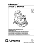
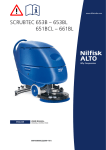
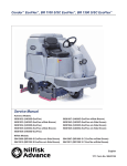
1
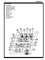
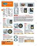
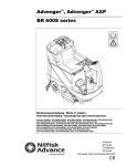
Electronic Service
Manuals
This electronic document is provided as a service to our customers. We do not create the contents of the information contained in
this document. Should you have detailed questions pertaining to
the information contained in this document, you may contact Michco,
or the manufacturer which provided the original information in this
electronic deliverable. Michco’s only part in this electronic deliverable was the electronic assembly process.
You may contact Michco through the following methods:
Phone (517) 484-9312 or (800) 331-3339 MI, OH, IN only
2011 N. High St. -- Lansing, Michigan -- 48906
Fax: (517) 484-9836
Email: [email protected]
Web site: www.Michco.Com
Parts Web site: www.FloorMachineParts.Com
Order Parts on Line at:
www.FloorMachineParts.Com
Directly to Parts & Service:
By Email: [email protected]
By Fax: (517) 702-2041
By Voice: Use numbers above.
Serving the Cleaning Industry Since 1922
Notice: All copyrighted material remains property of original owners, all trademarks are property of respective
owners. Manuals are subject to Manufacturer’s reproduction limitations. Originals or reproductions were provided
by manufacturers through a request. We make no warranty as to the correctness of information provided in this
document and you assume all risk.
Advenger™
BR 600S, 650S, 700S, 800S
Instructions For Use
Advance MODELS 56314000, 56314001, 56314002, 56314003,
56314004, 56314005, 56314006, 56314007
Nilfisk MODELS 56314010, 56314011, 56314012, 56314013,
56314014, 56314015, 56314016, 56314017
English
3/04 Form Number 56041554
ENGLISH / 3
TABLE OF CONTENTS
page
Introduction ...............................................................................................3
Cautions and Warnings ............................................................................4
Consignes de prudence et de sécurité .....................................................5
Know Your Machine ..................................................................................6
Control Panel ............................................................................................7
Know Your Machine Descriptions .............................................................8
Functional Description of Control Switches ..............................................9
Description of Indicators on the Control Panel .......................................10
Error Codes ............................................................................................ 11
Prepare the Machine for Use
Install the Batteries .................................................................................12
Install the Brushes ..................................................................................13
Install the Squeegee ...............................................................................14
Fill the Solution Tank ..............................................................................14
Operating the Machine ...........................................................................15
Scrubbing ...............................................................................................15
Wet Vacuuming ......................................................................................16
After Use.................................................................................................16
Maintenance Schedule ...........................................................................16
Lubricating the Machine .........................................................................16
Charging the Batteries ............................................................................17
Check the Battery Electrolyte Level........................................................17
Squeegee Maintenance..........................................................................18
Squeegee Adjustment ............................................................................18
Side Skirt Maintenance......................................................................19-20
Troubleshooting ......................................................................................21
Technical Specifications .........................................................................22
INTRODUCTION
This manual will help you get the most from your Nilfisk-Advance Rider Scrubber. Read it thoroughly before operating the machine.
Note: Bold numbers in parentheses indicate an item illustrated on pages 6-7.
This product is intended for commercial use only.
PARTS AND SERVICE
Repairs, when required, should be performed by your Authorized Nilfisk-Advance Service Center, who employs factory trained service personnel, and maintains
an inventory of Nilfisk-Advance original replacement parts and accessories.
Call the NILFISK-ADVANCE DEALER named below for repair parts or service. Please specify the Model and Serial Number when discussing your machine.
(Dealer, affix service sticker here.)
NAME PLATE
The Model Number and Serial Number of your machine are shown on the Nameplate on the machine. This information is needed when ordering repair parts
for the machine. Use the space below to note the Model Number and Serial Number of your machine for future reference.
MODEL NUMBER ______________________________________________________
SERIAL NUMBER ______________________________________________________
UNCRATE THE MACHINE
When the machine is delivered, carefully inspect the shipping carton and the machine for damage. If damage is evident, save the shipping carton so that it can
be inspected. Contact the Nilfisk-Advance Customer Service Department immediately to file a freight damage claim.
After removing the carton, cut the plastic straps and remove the wooden blocks next to the wheels. Use a ramp to roll the machine from the pallet to the floor.
FORM NO. 56041554 - Advenger™ / BR 600S, 650S, 700S, 800S - 3
4 / ENGLISH
CAUTIONS AND WARNINGS
SYMBOLS
Nilfisk-Advance uses the symbols below to signal potentially dangerous conditions. Always read this information carefully and
take the necessary steps to protect personnel and property.
DANGER!
Is used to warn of immediate hazards that will cause severe personal injury or death.
WARNING!
Is used to call attention to a situation that could cause severe personal injury.
CAUTION!
Is used to call attention to a situation that could cause minor personal injury or damage to the machine or other property.
GENERAL SAFETY INSTRUCTIONS
Specific Cautions and Warnings are included to warn you of potential danger of machine damage or bodily harm.
*
*
*
*
*
*
*
*
*
*
*
*
*
*
*
*
*
*
*
*
*
*
WARNING!
This machine shall be used only by properly trained and authorized persons.
While on ramps or inclines, avoid sudden stops when loaded. Avoid abrupt sharp turns. Use low speed down hills.
Clean only while ascending (driving up) the ramp.
Keep sparks, flame and smoking materials away from batteries. Explosive gases are vented during normal operation.
Charging the batteries produces highly explosive hydrogen gas. Charge batteries only in well-ventilated areas, away from
open flame. Do not smoke while charging the batteries.
Remove all jewelry when working near electrical components.
Turn the key switch off (O) and disconnect the batteries before servicing electrical components.
Never work under a machine without safety blocks or stands to support the machine.
Do not dispense flammable cleaning agents, operate the machine on or near these agents, or operate in areas where
flammable liquids exist.
Do not clean this machine with a pressure washer.
Only use the brushes provided with the appliance or those specified in the instruction manual. The use of other brushes
may impair safety.
CAUTION!
This machine is not approved for use on public paths or roads.
This machine is not suitable for picking up hazardous dust.
Do not use scarifier discs and grinding stones. Nilfisk-Advance will not be held responsible for any damage to floor surfaces caused by scarifiers or grinding stones (can also cause damage to the brush drive system).
When operating this machine, ensure that third parties, particularly children, are not endangered.
Before performing any service function, carefully read all instructions pertaining to that function.
Do not leave the machine unattended without first turning the key switch off (O), removing the key and applying the parking brake.
Turn the key switch off (O) and remove the key, before changing the brushes, and before opening any access panels.
Take precautions to prevent hair, jewelry, or loose clothing from becoming caught in moving parts.
Use caution when moving this machine in below freezing temperature conditions. Any water in the solution or recovery
tanks or in the hose lines could freeze, causing damage to valves and fittings. Flush with windshield washer fluid.
The batteries must be removed from the machine before the machine is scrapped. The disposal of the batteries should
be safely done in accordance with your local environmental regulations.
Do not use on surfaces having a gradient exceeding that marked on the machine.
All doors and covers are to be positioned as indicated in the instruction manual before using the machine.
SAVE THESE INSTRUCTIONS
4 - FORM NO. 56041554 - Advenger™ / BR 600S, 650S, 700S, 800S
ENGLISH / 5
CONSIGNES DE PRUDENCE ET DE SÉCURITÉ
SYMBOLES
Les symboles reproduits ci-dessous sont utilisés pour attirer l’attention de l’opérateur sur des situations dangereuses. Il est donc conseillé de lire attentivement ces indications et de prendre les mesures adéquates en vue de protéger le personnel et le matériel.
DANGER!
Ce symbole est utilisé pour mettre l’opérateur en garde contre les risques immédiats pouvant provoquer des dommages corporels graves, voire entraîner la
mort.
ATTENTION!
Ce symbole est utilisé pour attirer l’attention sur une situation susceptible d’entraîner des dommages corporels graves.
PRUDENCE!
Ce symbole est utilisé pour attirer l’attention de l’opérateur sur une situation qui pourrait entraîner des dommages corporels minimes, ou des dommages à la
machine ou à d’autres équipements.
CONSIGNES GENERALES DE SECURITE
Les consignes spécifiques de prudence et de sécurité mentionnées ici ont pour but de vous informer de la survenance de tout risque de dommages matériels
ou corporels.
*
*
*
*
*
*
*
*
*
*
*
*
*
*
*
*
*
*
*
*
*
*
ATTENTION!
Cette machine ne pourra être utilisée que par du personnel parfaitement entraîné et dûment autorisé.
Evitez les arrêts subits lorsque la machine est chargée et se trouve sur des rampes ou des plans inclinés. Evitez les virages serrés.
Adoptez une vitesse réduite lorsque la machine est en descente. Ne nettoyez que lorsque la machine monte la pente.
Eloignez les batteries de toutes flammes, étincelles ou substance fumigène. Les gaz explosifs sont ventilés pendant le fonctionnement normal.
De plus, du gaz hydrogène explosif s’échappe des batteries lorsqu’elles sont en charge. Ne procédez au chargement des batteries
que dans une zone bien ventilée, loin de toute flamme. Ne fumez pas à proximité des batteries lorsqu’elles sont en charge.
Otez tous vos bijoux lorsque vous travaillez à proximité de composants électriques.
Positionnez la clé de contact sur off (O) et déconnectez les batteries avant de procéder à l’entretien des composants électriques.
Ne travaillez jamais sous une machine sans y avoir placé, au préalable, des blocs de sécurité ou des étais destinés à soutenir la
machine
Ne déversez pas d’agents nettoyants inflammables, ne faites pas fonctionner la machine à proximité de ces agents ou d’autres liquides inflammables.
Ne nettoyez pas cette machine avec un nettoyeur à pression.
Utilisez uniquement les brosses fournies avec l’appareil ou celles spécifiées dans le manuel d’instructions. L’utilisation d’autres brosses peut mettre la sécurité en péril.
PRUDENCE!
Cette machine n’est pas conçue pour une utilisation sur les chemins ou voies publics.
Cette machine n’est pas conçue pour le ramassage des poussières dangereuses.
N’utilisez pas de disques de scarificateur ni de meules. Nilfisk-Advance ne pourra en aucun cas être tenue pour responsable des
dommages occasionnés à vos sols par ce type d’équipement (vous risquez également d’endommager le système d’entraînement des
brosses).
Lors de l’utilisation de cette machine, assurez-vous que des tiers, et notamment des enfants, ne courent pas le moindre risque.
Avant de procéder à toute opération d’entretien, veuillez lire attentivement toutes les instructions qui s’y rapportent.
Ne laissez pas la machine sans surveillance sans avoir, au préalable, coupé le contact, enlevé la clé de contact (O) et tiré le frein à
main.
Positionnez la clé de contact sur off (O) avant de remplacer les brosses ou d’ouvrir tout panneau d’accès.
Prenez toutes les mesures nécessaires pour éviter que les cheveux, les bijoux ou les vêtements amples ne soient entraînés dans les
parties mobiles de la machine.
Faites attention lorsque vous déplacez cette machine dans un endroit où la température peut descendre sous 0°. Car l’eau contenue
dans les réservoirs de solution ou de récupération ou dans les conduites risquerait de geler et par là même d’endommager les valves
et raccords de la machine. Rincez avec un liquide de lave-glace.
Prenez soin d’enlever les batteries de la machine avant de mettre cette dernière au rebut. Pour ce qui est de l’élimination des batteries, conformez-vous aux réglementations locales en matière d’environnement.
N’utilisez pas sur des surfaces dont la pente dépasse celle mentionnée sur la machine.
Toutes les portes et couvercles doivent être dans la position mentionnée dans le manuel d’instruction avant de mettre la machine en
service.
CONSERVEZ SOIGNEUSEMENT CES INSTRUCTIONS
FORM NO. 56041554 - Advenger™ / BR 600S, 650S, 700S, 800S - 5
6 / ENGLISH
KNOW YOUR MACHINE
1
2
3
4
5
6
7
8
9
10
11
12
13
14
15
16
17
18
19
20
21
22
23
24
25
26
Recovery Tank Cover
Solution Tank Fill Cover
Operator’s Seat
Solution Tank Drain Hose
Steering Wheel Tilt Adjust Knob
Brake Pedal / Parking Brake
Solution Flow Control Lever
Drive Pedal, Directional/Speed
Hopper (cylindrical models only)
Drive and Steer Wheel
Wheel Drive Circuit Breaker
Control Circuit Circuit Breaker
21
1
Emergency Stop Switch / Battery Disconnect
Scrub Deck
Rear Wheel
Battery Compartment (under seat)
Recovery Tank Shutoff Float
Vacuum Motor Filter Housing
Squeegee Assembly
Solution Filter
Recovery Tank Drain Hose
Machine Battery Connector
Control Panel
Squeegee Tilt Adjust Knob
Operator Seat Adjustment Lever
Smart Solutions™ / ECO Solution™
18
3
17
2
23
25
11
12
13
16
19
22
5
7
6
4
15
24
20
14
8
10
9
26
ON
OFF
6 - FORM NO. 56041554 - Advenger™ / BR 600S, 650S, 700S, 800S
ENGLISH / 7
CONTROL PANEL
A
B
C
D
E
F
G
H
I
J
K
L
M
N
O
P
Q
R
Scrub OFF Indicator
Scrub OFF Switch
Scrub Pressure Decrease Indicator
Scrub Pressure Decrease Switch
Scrub Pressure Increase Indicator
Scrub Pressure Increase Switch
Scrub Pressure / Hourmeter Display
Wand Switch Indicator
Wand Switch
Key Switch
Battery Condition Indicator
Speed Select Switch
Speed Select Indicator
Horn Switch
Vacuum Switch
Vacuum System Indicator
Solution System Indicator
Solution Switch
A
B
C
D
E
F
R
P
Q
G
O
H
N
I
M
L
K
J
FORM NO. 56041554 - Advenger™ / BR 600S, 650S, 700S, 800S - 7
8 / ENGLISH
KNOW YOUR MACHINE DESCRIPTIONS:
Recovery Tank Cover (1) – Open to access Recovery Tank for rinsing and(or) cleaning Float Cage.
Solution Tank Fill Cover (2) – Open to fill the solution tank, use non-foaming chemicals only.
Operator’s Seat (3) – The machine operator sits here. The seat has a safety switch which prevents the machine from moving without an operator in the
seat.
Solution Tank Drain Hose (4) – Used to empty the solution tank.
Steering Wheel Tilt Adjust Knob (5) – Push down on this knob to adjust the Steering Wheel up or down.
Brake Pedal / Parking Brake (6) – Push down to stop machine. NEVER leave machine unattended without setting Parking Brake.
Solution Flow Control Lever (7) – Move this lever UP to increase solution flow to the floor. Move DOWN to decrease the amount of solution flow to the floor.
When the Drive Pedal (8) is released from either forward or reverse travel, the solution flow will stop automatically, and resume when the drive is engaged.
Drive Pedal, Directional / Speed (8) – The operator can make the machine go forward by pushing forward on it, or reverse by pushing backward on it. The
speed is variable depending on how far forward or backward the pedal is moved. When the Scrub Deck (14) is in the “DOWN” position, the brushes, solution
and vacuum will operate when the drive pedal is engaged in either direction. The brushes stop after the drive pedal is in neutral for 1.5 seconds, the vacuum
stops after the drive pedal is in neutral for 10 seconds. NOTE: Solution only operates when moving forward.
Hopper (9) – Found only on cylindrical models, catches debris. Empty and clean daily.
Drive and Steer Wheel (10) – Wheel drive motor attached to this wheel to propel machine either forward or reverse. Also attached to Steering Wheel for
steering left or right.
Wheel Drive Circuit Breaker (11) – Provides overload protection to machine’s wheel drive motor. If it trips, it will pop out. To reset, wait one minute and press
the button back in. If any breaker trips repeatedly, have the machine serviced.
Control Circuit Circuit Breaker (12) – Provides overload protection. If it trips, it will pop out. To reset, wait one minute and press the button back in. If any
breaker trips repeatedly, have the machine serviced.
Emeregency Stop / Battery Disconnect (13) – Push in on lever to disconnect batteries.
Scrub Deck (14) – Contains brush drive motors and brushes.
Rear Wheel (15) – Rear wheel of machine.
Battery Compartment (16) – Batteries stored here, flip seat panel up to access.
Recovery Tank Shutoff Float (17) – Shuts off vacuum when recovery tank is full.
Vacuum Motor(s) Filter Housing (18) – Location of Vac Motor(s) air intake filter(s).
Squeegee Assembly (19) – Picks up solution after scrubbing.
Solution Filter (20) – Filters solution prior to dispensing on floor.
Recovery Drain Hose (21) – Used to empty the recovery tank.
Machine Battery Connector (22) – Batteries plug into this connector, disconnect to charge batteries.
Control Panel (23) – Operator Controls found here, see “FUNCTIONAL DESCRIPTION OF CONTROL SWITCHES”.
Squeegee Tilt Adjustment Knob (24) – Used to adjust the tilt of the squeegee forward or backward.
Operator Seat Adjustment Lever (25) - Use this lever to slide the operator’s seat forward or backward.
Smart Solutions™ / ECO Solution™ (26) – This valve is used when a consistent reduced flow of solution is desired. When the lever is in the “OFF” position; the machine operates conventionally; solution flow is determined with the Solution Flow Control Lever (7). When the lever is in the “ON” position; solution flow is controlled automatically. The Solution Flow Control Lever (7) should not be shut off, but is otherwise inactive. Make sure that the lever for Valve
(26) is all the way ON or all the way OFF, never in between.
8 - FORM NO. 56041554 - Advenger™ / BR 600S, 650S, 700S, 800S
ENGLISH / 9
FUNCTIONAL DESCRIPTION OF CONTROL SWITCHES:
The controls on the Advenger were designed with one touch operation in mind. For single pass scrubbing the user can simply depress one switch and all
systems on the machine will be ready to go.
For most single-pass scrubbing operations, the operator should only need to use the top three switches on the control panel. These are the Scrub System Off,
Scrub Pressure Decrease, and Scrub Pressure Increase switches.
Scrub Off Switch (B) - Pressing this switch when the unit is in a scrub mode will cause the following to occur:
•
The scrub brushes will turn off and the scrub deck will raise to the up position
•
The solution flow will be stopped
•
The first time that this switch is pressed, the vacuum/squeegee system will NOT be turned off. This is so that any remaining water may be picked up
without having to turn the vacuum back on. If this switch is pressed a second time (pressed after the scrub system has been turned off) the squeegee
will raise and the vacuum will shut of after a 10 second delay.
•
The travel speed limit will return to the transport speed setting.
Scrub Pressure Decrease Switch (D) – If the scrub system is off, pressing this switch will cause the following to occur:
•
The scrub system will be enabled with the scrub pressure set to the last used setting and the scrub deck will be lowered
•
The vacuum system will be enabled and the squeegee will be lowered
•
The solution system will be enabled
•
The travel speed will be limited to the scrub speed setting
•
As soon as the throttle is moved from the neutral position the scrub brushes will start turning and the vacuum will turn on. If the direction is forward
the solution flow will start. If the direction is reverse, the squeegee will raise and the solution flow will be stopped.
If the scrub system is already enabled when this switch is pressed, the scrub pressure will decrease. If the switch is held, the pressure will decrement until the
minimum setting of 1 is reached.
Scrub Pressure Increase Switch (F) – If the scrub system is off, pressing this switch will cause the following to occur:
•
The scrub system will be enabled with the scrub pressure set to the last used setting and the scrub deck will be lowered
•
The vacuum system will be enabled and the squeegee will be lowered
•
The solution system will be enabled
•
The travel speed will be limited to the scrub speed setting
•
As soon as the throttle is moved from the neutral position the scrub brushes will start turning and the vacuum will turn on. If the direction is forward
the solution flow will start. If the direction is reverse, the squeegee will raise and the solution flow will be stopped.
If the scrub system is already enabled when this switch is pressed, the scrub pressure will increase. If the switch is held, the pressure will increment until the
maximum programmed limit is reached (default = 9).
Wand Switch (I) – This switch is used when an external scrub wand is used. Pressing this switch will turn the vacuum on continuously without regard to the
throttle position. It will also enable the optional solution pump. If the scrub system was on it will be turned off. This includes turning off the scrub brushes and
raising the scrub deck, turning the solution flow off (to the scrub deck). The squeegee will be lowered to provide easier access to the recovery hose. NOTE:
automatic shutoff of the vacuum motor when the recovery tank is full is disabled when the wand is enabled. The float in the recovery tank will still prevent water
from entering the vacuum motor, but the motor will not shut off.
Key Switch (J) – Main power switch
Speed Select Switch (L) – This switch will allow the operator to select the transport speed limit while the scrub system is enabled thereby allowing scrubbing
at a higher rate of speed. This option can be disabled if desired. See the programming section for details.
The transport and scrub speed limits can be programmed using a Curtis handheld programmer. Refer to the service manual for details.
Horn Switch (N) – This switch will sound the horn as long as the switch is held.
The horn also functions as an automatic back-up alarm when the throttle is moved to the reverse position. The volume of the back-up alarm is programmable.
It can also be programmed to provide an annunciation feature that will sound whenever the drive pedal is in the forward position. See the programming section
for details.
Vacuum Switch (O) – This switch is used to turn the vacuum system on or off. When the vacuum is on the squeegee will lower (unless the machine is in
reverse) and when the vacuum is off the squeegee will raise. Pressing this switch will alternate between on and off. The vacuum will only turn on when the
throttle is moved from the neutral position. It will remain on for 10 seconds after the throttle returns to neutral.
The vacuum also has an automatic shutoff feature that will turn the vacuum and scrub systems off if the recovery tank becomes full. This feature can be disabled
if desired. The shutoff threshold can also be adjusted if necessary. See the programming section for details.
Solution Switch (R) - This switch is used to turn the solution system on or off. Pressing this switch when the scrub system has been activated will alternate
between on and off. The solution flow will only turn on when the throttle is moved from the neutral position in the forward direction. The solution flow will turn off
if the throttle returns to neutral or is moved to reverse.
Pressing this switch when the scrub system is off will momentarily turn the solution flow on to allow pre-wetting of the scrub brushes.
FORM NO. 56041554 - Advenger™ / BR 600S, 650S, 700S, 800S - 9
10 / ENGLISH
DESCRIPTION OF INDICATORS ON THE CONTROL PANEL:
In general, the following guidelines apply to the control panel indicators:
A steady red indicator means that the function is inhibited for some reason. For example, if the scrub system is off and the operator is not on the seat, the
scrub system indicator will be red indicating that the system cannot be turned on until the operator is on the seat.
A flashing red or yellow indicator means that a fault has occurred in the particular system. An example of this would be an over-current fault.
A yellow indicator means that the particular function has been enabled but is not currently on. For example, if a scrub mode is selected and the throttle is in
neutral, the scrub system, vacuum, and solution indicators will all be yellow indicating that the systems are enabled and ready to turn on when the throttle is
moved to forward or reverse.
A green indicator means that the particular system is on.
A flashing green indicator means that the particular system is in a delayed-off condition. An example of this is when a scrub mode is selected and the
throttle goes from forward or reverse to neutral. When this happens the vacuum indicator will flash green indicating that the vacuum is still on but that it will
be turning off after the delay period.
Scrub Off Indicator (A):
•
This indicator will be green if the scrub system is off and ready to be activated.
•
This indicator will be red if the scrub system has been turned off and the scrub deck is not up yet, or if the scrub deck is up and there is no weight on
the seat.
•
This indicator will flash red if there is a fault in the scrub system.
•
This indicator will be off if the scrub system has been activated.
Scrub Pressure Decrease Indicator (C):
•
This indicator will be yellow if the scrub system is enabled but the drive pedal is at neutral and the current scrub pressure is at 2 or more.
•
This indicator will be green if the scrub system has been turned on, the current scrub pressure is at 2 or more and the machine is moving in either
direction.
•
This indicator will be off if the scrub system has been turned OFF or the scrub pressure is set at 1.
Scrub Pressure Increase Indicator (E):
•
This indicator will be yellow if the scrub system is enabled but the drive pedal is at neutral and the current scrub pressure is at 8 or less.
•
This indicator will be green if the scrub system has been turned on, the current scrub pressure is at 8 or less and the machine is moving in either
direction.
•
This indicator will be off if the scrub system has been turned OFF or the scrub pressure is set at 9.
Scrub Pressure/Hourmeter Display (G):
The single character display on the control panel is primarily used as a display for the scrub pressure. This display is also used to display the machine hours
and any control system fault codes.
If any of the systems on the machine are on or if the throttle is not in neutral, the display will indicate the scrub pressure setting (1-9). If the scrub system is off
the display will indicate 0.
Upon power-up or if the machine has been idle for at least ten seconds with all systems turned off, the display will indicate the machine hours. The format for
the display of the hours is as follows:
Example 123.4 hours
•
The display will indicate 1 followed by a short blank period
•
The display will indicate 2 followed by a short blank period
•
The display will indicate 3 followed by a short blank period
•
The display will indicate _ followed by a short blank period, this is used as a decimal point to indicate tenths of hours
•
The display will indicate 4 (tenths) followed by a long blank period
•
The display sequence will repeat
If an overload fault occurs, the display will indicate the associated error code immediately. If an open or short fault occurs, the error will be displayed if the scrub
system is not active. The format for the display of error codes is as follows:
Example: error code 6, and error code 18
•
The display will indicate E followed by a short blank period
•
The display will indicate 0 followed by a short blank period
•
The display will indicate 6 followed by a slightly longer blank period
•
The display will indicate E followed by a short blank period
•
The display will indicate 1 followed by a short blank period
•
The display will indicate 8 followed by a slightly longer blank period
•
The display sequence will repeat
NOTE: If a speed control fault occurs (error code 3) the wand indicator will flash the fault code produced by the Curtis speed control. Refer to the service
manual troubleshooting section for details.
10 - FORM NO. 56041554 - Advenger™ / BR 600S, 650S, 700S, 800S
ENGLISH / 11
Wand Switch Indicator (H):
•
This indicator will be green if the Wand Switch has been turned ON.
•
This indicator will be off if the Wand Switch has been turned OFF.
Speed Selector Indicator (M):
•
This indicator will be green if a scrub mode has been selected and the faster scrub speed has been selected.
•
This indicator will be off if the Speed Select Switch has been turned OFF.
Vacuum System Indicator (P):
•
This indicator will be green if the vacuum is on.
•
This indicator will flash green if the vacuum is in the 10 second delayed-off condition.
•
This indicator will be yellow if the vacuum is enabled but the drive pedal is in neutral.
•
This indicator will flash yellow if there is a vacuum system fault.
•
This indicator will be off if the vacuum is disabled and turned off.
Solution System Indicator (Q):
•
This indicator will be green if the solution is on.
•
This indicator will be yellow if the solution is enabled but the drive pedal is in neutral.
•
This indicator will flash yellow if there is a solution system fault.
•
This indicator will be off if the solution is disabled and turned off.
Power Saving Sleep Function
The Advenger is equipped with a battery saving feature that will turn all of the machine systems and accessories off if the machine is left in an idle state for a
preset period of time. This sleep mode will only occur if the operator is not on the seat and the wand function is not in use. The sleep mode is indicated by a
short duration green flashing scrub system off indicator. The sleep function is automatically cancelled when the operator sits on the seat or any of the control
switches are pressed. The sleep delay period is adjustable from 10 to 90 minutes in 10 minute increments. The default period is 10 minutes. It can also be
disabled. Refer to the service manual for changing the delay period.
CONTROL SYSTEM ERROR CODES
Display Code .................... Fault description
01....................................... Non-Critical Control
02....................................... Critical Control
03....................................... Speed Control
04....................................... Scrub Deck Lift Actuator Overload
05....................................... Squeegee Lift Actuator Overload
06....................................... Brush Motor Overload
07....................................... Vacuum Motor Overload
08....................................... Contactor / Solution Solenoid Overload
17....................................... Scrub Deck Lift Actuator Open
18....................................... Scrub Deck Lift Actuator Short
19....................................... Squeegee Lift Actuator Open
20....................................... Squeegee Lift Actuator Short
21....................................... Brush Motor open
22....................................... Brush Motor Short
23....................................... Vacuum Motor Open
24....................................... Vacuum Motor Short
25....................................... Contactor / Solution Solenoid Open
26....................................... Contactor / Solution Solenoid Short
27....................................... No Accessory / Wiring
FORM NO. 56041554 - Advenger™ / BR 600S, 650S, 700S, 800S - 11
12 / ENGLISH
DESCRIPTION OF THE BATTERY CONDITION INDICATORS
The battery condition indicator (J) consists of three lights, a green (G), a yellow (Y), and a red (R). The voltage indication will change based on the cutoff level
(standard or alternate) selected in the control unit. The battery voltage ranges for the various indications are listed below:
Standard
Alternate
Green
34.00+
34.50+
Green & Yellow
33.00-33.99
34.00-34.49
Yellow
32.00-32.99
33.50-33.99
Yellow & Red
31.50-31.99
33.00-33.49
Red
31.00-31.49
32.50-32.99
Flashing Red/Cutoff
<31.00
<32.50
NOTE: Refer to service manual for selection of alternate cut-off level. Once the low voltage cutout level has been reached (flashing red indicator) the batteries
must be FULLY recharged to reset the battery condition indicator. The scrub system will not function until the indicator has been reset.
INSTALL THE BATTERIES
WARNING !
Use extreme caution when working with batteries. Sulfuric acid in batteries can cause severe injury if allowed to contact the skin
or eyes. Explosive hydrogen gas is vented from inside the batteries through openings in the battery caps. This gas can be ignited
by any electrical arc, spark or flame.
When Servicing Batteries...
*
Remove all jewelry.
*
Do not smoke.
*
Wear safety glasses, a rubber apron and rubber gloves.
*
Work in a well-ventilated area.
*
Do not allow tools to touch more than one battery terminal at a time.
CAUTION !
Electrical components in this machine can be severely damaged if the batteries are not installed and connected properly. Batteries
should be installed by Nilfisk-Advance or by a qualified electrician.
1
2
3
4
5
Turn the Key Switch (J) off (O) and remove the key. Then swing open the Battery Compartment Cover (16).
Using (2) people and an appropriate lifting strap, carefully lift the batteries into the compartment tray exactly as shown. Refer to decal 56015168
battery cable layout.
See Figure 1. Install battery cables as shown and tighten the nuts on the battery terminals.
Install the battery boots and secure tightly to the battery cables with the supplied tie straps.
Connect the battery pack connector to the machine connector (22) and close the battery compartment cover.
FIGURE 1
12 - FORM NO. 56041554 - Advenger™ / BR 600S, 650S, 700S, 800S
ENGLISH / 13
INSTALL THE BRUSHES (DISC SYSTEM)
CAUTION !
Turn the key switch off (O) and remove the key, before changing the brushes, and before opening any access panels.
1
Make sure the Key Switch (J) is off (O). To access the brushes, remove both side skirt assemblies. Note: The skirts are held in place by a two large Knobs, loosen
these knobs and slide the skirt assemblies off of the Scrub Deck.
2 To mount the brushes (or pad holders) align the lugs on the brush with the holes on the mounting plate and turn to lock in place (turn outside edge of brush towards front of
machine).
24 Inch Models
26 Inch Models
28 Inch Models
32 Inch Models
56505751 - Magna Grit 46
56505761 - Magna Grit 46
56505801 - Magna Grit 46
56505831 - Magna Grit 46
56505752 - Dyna Grit 80
56505762 - Dyna Grit 80
56505802 - Dyna Grit 80
56505832 - Dyna Grit 80
56505753 - AgLite Grit 500
56505763 - AgLite Grit 500
56505803 - AgLite Grit 500
56505833 - AgLite Grit 500
56505754 – Prolene
56505764 – Prolene
56505804 – Prolene
56505834 – Prolene
56505755 – ProLite
56505765 – ProLite
56505805 – ProLite
56505835 – ProLite
56505756 - Union Mix
56505766 - Union Mix
56505806 - Union Mix
56505836 - Union Mix
56505757 - MidGrit 240
56505767 - MidGrit 240
56505807 - MidGrit 240
56505837 - MidGrit 240
56505758 - MidLite Grit 180
56505768 - MidLite Grit 180
56505808 - MidLite Grit 180
56505838 - MidLite Grit 180
DISC BRUSH APPLICATION GUIDE (SUGGESTION ONLY)
Application
Stripping:
Concrete
Terrazo
Ceramic/Quarry tile
Vinyl tile
General Scrubbing:
Concrete
Terrazo
Ceramic/Quarry tile
Marble
Vinyl tile
Raised-rubber tile
Polishing:
Raised Disc Tile
Marble
Vinyl tile
46
Grit
80
Grit
X
X
X
X
X
X
X
X
180
Grit
240
Grit
X
X
X
X
X
X
X
500
Grit
X
X
X
X
X
Prolene
Prolite
Union
Mix
X
X
X
X
X
X
X
X
X
INSTALL THE BRUSHES (CYLINDRICAL SYSTEM)
CAUTION !
Turn the key switch off (O) and remove the key, before changing the brushes, and before opening any access panels.
1
Make sure the Key Switch (J) is off (O). To access the brushes, swing both side skirt assemblies open. Note: The skirts are held in place by a large cotter pin on each
side, remove the pins and swing the skirt assemblies out of the way. Loosen the black knobs (one on each side) on top of the idler assemblies and remove the idler
assemblies. Slide the brush into the housing, lift slightly, push and turn until it seats. Re-install the idler assemblies, close the skirt assemblies and secure with cotter
pins.
24 Inch Models
56314389 - Soft Nylon
56314390 - Stiff Nylon
56314391 – Polypropylene
56314392 - 180 Grit
56314393 - 80 Grit
56314394 - 46 Grit
26 Inch Models
56314383 - Soft Nylon
56314384 - Stiff Nylon
56314385 – Polypropylene
56314386 - 180 Grit
56314387 - 80 Grit
56314388 - 46 Grit
28 Inch Models
56412191 - Soft Nylon
56412192 - Stiff Nylon
56412046 – Polypropylene
56412193 - 180 Grit
56412194 - 80 Grit
56412195 - 46 Grit
32 Inch Models
56407473 - Soft Nylon
56407474 - Stiff Nylon
56407475 – Polypropylene
56407476 - 180 Grit
56407477 - 80 Grit
56407478 - 46 Grit
CYLINDRICAL BRUSH APPLICATION GUIDE (SUGGESTION ONLY)
Application
Stripping:
Concrete
Terrazo
Ceramic/Quarry tile
Vinyl tile
General Scrubbing:
Concrete
Terrazo
Ceramic/Quarry tile
Marble
Vinyl tile
Raised-rubber tile
46
Grit
80
Grit
X
X
X
X
X
X
X
X
180
Grit
Polypropylene
Stiff
Nylon
X
X
X
X
X
X
X
X
X
X
X
X
X
X
X
Soft
Nylon
X
X
X
X
X
FORM NO. 56041554 - Advenger™ / BR 600S, 650S, 700S, 800S - 13
14 / ENGLISH
INSTALL THE SQUEEGEE
1
2
Make sure the Squeegee (19) is up (O) and the Key Switch (J) is off (O). Hold the squeegee tool so that the curved ends point forward, then slide
the squeegee tool onto the Mount (A) (See Figure 2).
Hand tighten the Thumb Nuts (B) and then connect the vacuum hose to the Squeegee Tube (C) (vacuum hose should loop to the right).
FILL THE SOLUTION TANK
Read the cleaning chemical label and figure the proper amount of chemical to mix for a tank that holds 30 US gallons (113 liters).
Open the Solution Tank Cover (2), then fill the tank 1/3 full of water, add the cleaning chemical, then fill the tank to 7.62cm (3 inches) from the top of the tank
opening (fill to bottom of the wall in tank opening).
CAUTION !
Use only low-foaming, non-flammable liquid detergents intended for automatic scrubber machine applications.
FIGURE 2
FRONT
B
C
A
14 - FORM NO. 56041554 - Advenger™ / BR 600S, 650S, 700S, 800S
ENGLISH / 15
OPERATING THE MACHINE
WARNING !
Be sure you understand the operator controls and their functions.
While on ramps or inclines, avoid sudden stops when loaded. Avoid abrupt sharp turns. Use low speed down hills. Clean only
while ascending (driving up) the ramp.
To Scrub...
Follow the instructions in preparing the machine for use section of this manual.
1
While seated on the machine, adjust the seat and steering wheel to a comfortable operating position using the adjustment controls (25) and (5).
2
Turn the Master Key Switch (J) ON (I). This will display the control panel indicator lights, reference the Battery Condition Indicator (K) and Hour
Meter (G).
3
Release the Parking Brake (6). To transport the machine to the work area, apply even pressure with your foot on the front of the Drive Pedal (8) to
go forward or the rear of the pedal for reverse. Vary the pressure on the foot pedal to obtain the desired speed.
4
Adjust the Solution Flow Control Valve Lever (7) to about 1/4 to 1/3 open position. Note the adjustment can be changed to allow variable solution
flow for different types of floors to be scrubbed. Example: A rough or absorbent floor surface, such as unfinished concrete, well require more solution
than a smooth finished floor.
NOTE: For a consistent reduced flow of solution; open the Solution Flow Control Valve Lever (7) all the way and then turn ON the Smart Solutions™
/ ECO Solution™ valve.
5
Press the Solution Switch (R) and hold for 5 seconds. This is done to pre-wet the floor. Note: This will help prevent scarring of the floor surface
when starting to scrub with dry brushes.
6
Press the Scrub Pressure Decrease Switch (D) or the Scrub Pressure Increase Switch (F) to activate the scrub system. Note: refer to the Functional
Description of Control Switches section for a more detailed explanation of these and other control panel functions.
7
When the Scrub Pressure Decrease Switch (D) or the Scrub Pressure Increase Switch (F) are selected, the brushes and squeegee are automatically
lowered to the floor. The machine’s scrub brush rotation, solution system flow and vacuum starts when the Drive Pedal (8) is activated. Note: When
operating the machine in reverse, only the brushes will rotate, the solution is automatically shut off to conserve the solution usage.
8
Begin scrubbing by driving the machine forward in a straight line at a normal walking speed and overlap each path by 2-3 inches (50-75 mm). Adjust
when necessary the machine speed and solution flow according to the condition of the floor.
CAUTION !
To avoid damaging the floor, keep the machine moving while the brushes are turning.
9
10
11
12
13
When scrubbing, check behind the machine occasionally to see that all of the waste water is being picked up. If there is water trailing the machine,
you may be dispensing too much solution, the recovery tank may be full, or the squeegee tool may require adjustment.
For extremely dirty floors, a one-pass scrubbing operation may not be satisfactory and a “double-scrub” operation may be required. This operation is
the same as a one-pass scrubbing except on the first pass the squeegee is in the up position (press the Vacuum Switch (O) to raise the squeegee).
This allows the cleaning solution to remain on the floor to work longer. The final pass is made over the same area, with the squeegee lowered to pick
up the accumulated solution.
The recovery tank has an automatic float shut-off to prevent solution from entering the vacuum system when the recovery tank is full. When the float
shut-off is activated, the control system will shut down the scrub, vacuum and solution systems. The Scrub Pressure / Hourmeter Display (G) will
display “FULL”. To clear the display, press the Scrub OFF Switch (B), Scrub Pressure Decrease Switch (D), Scrub Pressure Increase Switch (F) or
the Vacuum Switch (O). When the float closes, the recovery tank must be emptied. The machine will not pick up water with the float closed. NOTE:
If the control repeatedly gives a full indication when the tank is not full, the automatic shut-off feature can be disabled, have a qualified service technician refer to the service manual to perform this function.
When the operator wants to stop scrubbing or the recovery tank is full, press the Scrub OFF Switch (B) once. This will automatically stop the scrub
brushes and solution flow and the scrub deck will raise UP. NOTE: the vacuum/squeegee system will not be turned off when the switch is only
pressed once, this is to allow any remaining water to be picked up without turning the vacuum back on. Press the switch a second time and the
squeegee will raise and the vacuum will stop after a 10 second delay.
Drive the machine to a designated waste water “DISPOSAL SITE” and empty the recovery tank. To empty, pull the Drain Hose (21) from its rear
storage area, then remove the plug (hold the end of the hose above the water level in the tank to avoid sudden, uncontrolled flow of waste water).
Refill the solution tank and continue scrubbing.
FORM NO. 56041554 - Advenger™ / BR 600S, 650S, 700S, 800S - 15
16 / ENGLISH
WET VACUUMING
Steps to follow in fitting the machine with optional attachments for wet vacuuming.
1
Disconnect the recovery hose from the squeegee. Connect the coupler and hose from the wand kit to the recovery hose.
2
Attach suitable wet pick-up tools to the hose. (An optional Wand Kit PN56314307 is available from Nilfisk-Advance).
3
Turn the Master Key Switch (J) ON, next press the Wand Switch (I). The vacuum motor and pump will run continuously until the switch is pressed
again to turn them OFF. NOTE: If the control repeatedly gives a full indication when the tank is not full, the automatic shut-off feature can be disabled, have a qualified service technician perform this function.
AFTER USE
1
2
3
4
5
6
7
When finished scrubbing, press the Scrub Off Switch (B) twice, this will automatically raise, retract and stop all the machine systems (brush, squeegee, vacuum & solution). Then drive the machine to a service area for daily maintenance and review of other needed service up keep.
To empty the solution tank, remove the Solution Drain Hose (4) from it’s storage clamp. Direct the hose to a designated “DISPOSAL SITE” and
remove the plug. Rinse the tank with clean water.
To empty the recovery tank, pull the Recovery Tank Drain Hose (21) from its storage area. Direct the hose to a designated “DISPOSAL SITE” and
remove the plug (hold the end of the hose above the water level in the tank to avoid sudden, uncontrolled flow of waste water). Rinse the tank with
clean water.
Remove the brushes or pad holders. Rinse the brushes or pads in warm water and hang up to dry.
Remove the squeegee, rinse it with warm water and re-install on mount.
Remove the hopper on cylindrical systems and clean thoroughly. Remove from either side of the machine by opening the skirt and tilting the hopper
up and away from housing, then pull out.
Check the maintenance schedule below and perform any required maintenance before storage
MAINTENANCE SCHEDULE
MAINTENANCE ITEM
Charge Batteries
Check/Clean Tanks & Hoses
Check/Clean/Rotate the Brushes/Pads
Check/Clean the Squeegee
Check/Clean Vacuum Shut-Off Float
Check/Clean the vacuum motor foam filter(s)
Clean Hopper on Cylindrical System
Check Each Battery Cell(s) Water Level
Inspect Scrub Housing Skirts
Inspect and clean Solution Filter
Check Foot/ Parking Brake For Wear & Adjustment
Clean Solution Trough on Cylindrical System
Lubrication - Grease Fittings
* Check Carbon Brushes
Daily
X
X
X
X
X
X
X
Weekly
Monthly
Yearly
X
X
X
X
X
X
X
* Have Nilfisk-Advance check the vacuum motor carbon motor brushes once a year or after 300 operating hours. The brush and drive motor carbon brushes
check every 500 hours or once a year.
NOTE: Refer to the Service Manual for more detail on maintenance and service repairs.
8
Store the machine indoors in a clean dry place. Keep from freezing. Leave the tanks open to air them out.
9
Turn the Master Key Switch (J) OFF (O) and remove the key.
LUBRICATING THE MACHINE
Once a month, pump a small amount of grease into each grease fitting on the machine until grease seeps out around the bearings.
Grease fitting locations are:
•
Squeegee Caster Wheel Axle
•
Steering Wheel Shaft Universal joint
Once a month, apply light machine oil to lubricate the:
•
Steering Chain
•
General Pivot Points For the Squeegee, Brush Linkage and Side Skirts
•
Squeegee mount angle adjustment knob threads
16 - FORM NO. 56041554 - Advenger™ / BR 600S, 650S, 700S, 800S
ENGLISH / 17
CHARGING THE BATTERIES
Charge the batteries each time the machine is used, or whenever the Battery Condition Meter (K) is showing a yellow , red or flashing red indicator light(s).
To Charge the Batteries...
1
Depress the Battery Disconnect (13).
2
Open the Battery Compartment Cover (16) to provide proper ventilation.
3
Push the connector from the charger into the Battery Connector (22).
4
Follow the instructions on the battery charger.
5
Check the fluid level in all battery cells after charging the batteries. Add distilled water, if necessary, to bring the fluid level up to the bottom of the
filler tubes.
WARNING !
Do not fill the batteries before charging.
Only charge batteries in a well-ventilated area.
Do not smoke while servicing the batteries.
CAUTION !
To avoid damage to floor surfaces, always wipe water and acid from the top of the batteries after charging.
CHECKING THE BATTERY ELECTROLYTE LEVEL
Check the electrolyte level of the batteries at least once a week.
After charging the batteries, remove the vent caps and check the electrolyte level in each battery cell. Use distilled water to fill the batteries to the bottom of
the filler tube.
Do not over-fill the batteries!
CAUTION !
Acid can spill onto the floor if the batteries are overfilled.
Tighten the vent caps. If there is acid on the batteries, wash the tops of the batteries with a solution of baking soda and water (2 tablespoons of baking soda
to 1 quart of water).
FORM NO. 56041554 - Advenger™ / BR 600S, 650S, 700S, 800S - 17
18 / ENGLISH
SQUEEGEE MAINTENANCE
If the squeegee leaves narrow streaks or water, the blades may be dirty or damaged. Remove the squeegee, rinse it under warm water and inspect the blades.
Reverse or replace the blades if they are cut, torn, wavy or worn.
To Reverse or Replace the Rear Squeegee Wiping Blade...
1
See Figure 3. Raise the squeegee tool off the floor, then unsnap the Center Latch (A) on the squeegee tool.
2
Remove the Tension Straps (B).
3
Slip the rear blade off the alignment pins.
4
The squeegee blade has 4 working edges. Turn the blade so a clean, undamaged edge points toward the front of the machine. Replace the blade if
all 4 edges are nicked, torn or worn to a large radius.
5
Install the blade, following the steps in reverse order and adjust the squeegee tilt.
To Reverse or Replace the Front Squeegee Blade...
1
Raise the squeegee tool off the floor, then loosen the (2) Thumb Nuts (C) on top of the squeegee and remove the squeegee tool from the mount.
2
Remove both rear Tension Straps first.
3
Remove all the wing nuts that hold the front blade in place, then remove tension strap and blade.
4
The squeegee blade has 4 working edges. Turn the blade so a clean, undamaged edge points toward the front of the machine. Replace the blade if
all 4 edges are nicked, torn or worn to a large radius.
5
Install the blade, following the steps in reverse order and adjust the squeegee tilt.
SQUEEGEE ADJUSTMENT
There is just one squeegee tool adjustment possible, angle.
Adjusting the Squeegee Angle
Adjust the squeegee angle whenever a blade is reversed or replaced, or if the squeegee is not wiping the floor dry.
1
Park the machine on a flat, even surface and lower the squeegee. Then drive the machine forward enough to have the squeegee blades fold over to
the rear.
2
Loosen the Lock Wing Nut (D) (hand tightened). This secures the squeegee mount angle from easily vibrating out of adjustment.
3
Turn the Adjustment Knob (E) to tilt the tool forward or backwards, until the rear squeegee wiping blade touches the floor evenly across its entire
width.
4
Re-tighten by hand the Lock Wing Nut (D).
C
FIGURE 3
C
FRONT
E
D
B
A
B
18 - FORM NO. 56041554 - Advenger™ / BR 600S, 650S, 700S, 800S
ENGLISH / 19
SIDE SKIRT MAINTENANCE (DISC SYSTEM)
The side skirt’s function is to channel the waste water to the squeegee, helping contain the water within the machines cleaning path. During normal use the
blades will wear in time. The operator will notice a small amount of water leaking out underneath the side skirts. A height adjustment can easily be made to
lower the blades so that all the water can be pick-up by the squeegee.
To reverse or replace the scrub system side skirt(s) ...
1
See Figure 4. Loosen the (2) side skirt Retainer Knobs (A) (2 per side) and pull the Skirt Assemblies (B) off from the scrub deck.
2
Remove all the hardware that holds the blades to the skirt housings.
3
Replace the blades as a set if they are nicked, torn or worn beyond their ability to be adjusted.
4
Reinstall the skirt housing assemblies onto the machine and adjust the blade for proper contact to the floor when the brush deck is placed in the
scrub position.
SIDE SKIRT HEIGHT ADJUSTMENT (DISC SYSTEM)
1
2
3
The side skirt housing knob retainer screw studs have leveling Adjuster Collars (C), that are to be raised or lowered to compensate for blade wear.
To adjust, remove the Skirt Assemblies (B) from the Scrub Deck (D) to access the Adjuster Collars (C). Adjustment Tip: The skirts Retainer Knobs
(A) can be loosened with skirts left on and the Adjuster Collars (C) rotated by reaching under the skirt housing.
Turn the Adjuster Collars (C) (Up or Down) to where the blades just fold over enough when scrubbing that all the waste water is contained inside the
skirting. Note: Make small adjustments to obtain good blade wiping. Do not lower the blades too much to where they fold over excessively and
cause unneeded blade wear.
FIGURE 4
FRONT
A
C
B
D
FORM NO. 56041554 - Advenger™ / BR 600S, 650S, 700S, 800S - 19
20 / ENGLISH
SIDE SKIRT MAINTENANCE (CYLINDRICAL SYSTEM)
The side skirts function is to channel the waste water to the squeegee, helping contain the water within the machines cleaning path. During normal use the
blades will wear in time. The operator will notice a small amount of water leaking out underneath the side skirts. Skirt height adjustment is automatic on this
system. The skirt assemblies should move up and down freely for proper operation.
To replace the scrub system side skirt(s) ...
1
See Figure 5. Remove the (2) (A) Cotter Pins and swing the Skirt Assemblies open. Remove the (B) Screws and Nuts, remove the Skirts and
replace.
FIGURE 5
A
FRONT
B
20 - FORM NO. 56041554 - Advenger™ / BR 600S, 650S, 700S, 800S
ENGLISH / 21
GENERAL MACHINE TROUBLESHOOTING
Problem
Possible Cause
Remedy
Poor water pick-up
Worn or torn squeegee blades
Squeegee out of adjustment
Recovery tank full
Recovery tank drain hose leak
Recovery tank cover gasket leak
Debris caught in squeegee
Vacuum hose clogged
Using too much solution
Foam filter cover not seated
Reverse or replace
Adjust so blades touch floor evenly
across entire width
Empty recovery tank
Secure drain hose cap or replace
Replace gasket / Seat cover properly
Clean squeegee tool
Remove debris
Adjust solution control valves
Seat cover properly
Poor scrubbing performance
Worn brush or pad
Wrong brush or pad type
Wrong cleaning chemical
Moving machine too fast
Not using enough solution
Rotate or replace brushes
Consult Nilfisk-Advance
Consult Nilfisk-Advance
Slow down
Adjust solution control valves
Inadequate solution flow
or no solution
Solution tank empty
Fill solution tank
Solution lines, valves, filter or trough clogged
Solution control valves not open
Solution solenoid valve
Flush lines, trough and clean solution filter
Adjust solution control valves
Clean or replace valve
Machine does not run
Emergency stop switch tripped
Operator seat safety switch
Main system controller
Reconnect battery connectors
Check for open circuit and replace
Check error fault codes
(see service manual)
Check for electrical short circuit & reset
Tripped 10 Amp circuit breaker
No FWD/REV wheel drive
Drive system speed contoller
Tripped 45 Amp circuit breaker
Emergency stop switch tripped
Check error fault codes
(see service manual)
Check for drive motor overload
Reconnect battery connectors
Vacuum shuts off and display shows
“FULL” when recovery tank is not full
Plugged squeegee hose
Clear debris
Vacuuming large amounts of water
at a high travel speed
Slow down or disable auto shut-off feature
(see service manual)
Poor Sweeping Performance
(Cylindrical System)
Hopper Full
Empty and clean hopper
Brushes worn
Bristles have taken a set
Replace brushes
Rotate brushes
FORM NO. 56041554 - Advenger™ / BR 600S, 650S, 700S, 800S - 21
22 / ENGLISH
TECHNICAL SPECIFICATIONS (as installed and tested on the unit)
Model
Model No.
Voltage, Batteries
Battery Capacity
Protection Grade
Sound Power Level (IEC 704-1)
Gross Weight
Vibrations at the Hand Controls
Vibrations at the Seat
Gradeability
Transport
Cleaning
Model
V
Ah
dB(A)/20µPa
lbs / kg
m/s2
m/s2
Model No.
Voltage, Batteries
Battery Capacity
Protection Grade
Sound Power Level (IEC 704-1)
Gross Weight
Vibrations at the Hand Controls
Vibrations at the Seat
Gradeability
Transport
Cleaning
V
Ah
dB(A)/20µPa
lbs / kg
m/s2
m/s2
BR 600S
Advenger™ 2400D
56314010
56314000
36V
305
IPX3
70
1,380 / 626
<2.5m/s2
<0.5m/s2
BR 650S
Advenger ™ 2600D
56314011
56314001
36V
305
IPX3
70
1,385 / 628
<2.5m/s2
<0.5m/s2
BR 700S
Advenger ™ 2810D
56314012
56314002
36V
305
IPX3
70
1,385 / 628
<2.5m/s2
<0.5m/s2
BR 800S
Advenger™ 3210D
56314013
56314003
36V
305
IPX3
70
1,390 / 630
<2.5m/s2
<0.5m/s2
14% (80)
10% (60)
BR 600CS
Advenger™ 2400C
56314014
56314004
36V
305
IPX3
70
1,385 / 628
<2.5m/s2
<0.5m/s2
14% (80)
10% (60)
BR 650CS
Advenger ™ 2600C
56314015
56314005
36V
305
IPX3
70
1,390 / 630
<2.5m/s2
<0.5m/s2
14% (80)
10% (60)
BR 700CS
Advenger ™ 2810C
56314016
56314006
36V
305
IPX3
70
1,390 / 630
<2.5m/s2
<0.5m/s2
14% (80)
10% (60)
BR 800CS
Advenger™ 3210C
56314017
56314007
36V
305
IPX3
70
1,395 / 633
<2.5m/s2
<0.5m/s2
14% (80)
10% (60)
14% (80)
10% (60)
14% (80)
10% (60)
14% (80)
10% (60)
22 - FORM NO. 56041554 - Advenger™ / BR 600S, 650S, 700S, 800S
Austria (Sales Sub)
Nilfisk-Advance GmbH
Voralberger Allee 46
A-1230 Wien
[email protected]
www.nilfisk-advance.at
Belgium (Sales Sub)
Nilfisk-Advance NV/SA
Doornveld Sphere Business Park
Industrie Asse 3, No. 11
B-1731 Zellik-Asse
www.nilfisk-advance.be
Czech Republic (Sales Sub)
Nilfisk-Advance s.r.o.
Lysinská 44/1863
143 00 Praha - Modrany
Czech Republic
Denmark
Nilfisk-Advance A/S
Sognevej 25
DK-2605 Brøndby
[email protected]
www.nilfisk-advance.com
Denmark (Prod. Sub)
Gerni A/S
Myntevej 2
DK-8900 Randers
www.gerni.com
Denmark (Sales Sub)
Nilfisk-Advance Nordic A/S
Sognevej 25A
Postbox 344
DK-2605 Brøndby
[email protected]
www.nilfisk-advance.dk
France (Sales Sub)
Nilfisk-Advance S.A.
27 avenue de la Baltique
Villebon sur Yvette
P.B. 246
F-91944 Courtaboeuf Cedex
[email protected]
www.nilfisk-advance.fr
Germany (Sales Sub)
Nilfisk-Advance AG
Siemensstrasse 25-27
Postfach 1361
D-25462 Rellingen
info@nilfisk-advancede
www.nilfisk-advance.de
Greece (Sales Sub)
Nilfisk-Advance A.E.
8, Thoukididou Str.
Argioupoli
Gr - 164 52 Athens
Greece
Phone: +43
1616 58 30 22
Fax: +43
1616 58 30 40
Phone: +32
(0)2467 60 50
Fax: +32
(0)2463 44 16
Phone: +420
2 44 09 09 12
+420
2 44 09 09 21 4
Fax: +420
2 44 40 23 93
Phone: +45
43 23 81 00
Fax: +45
43 43 77 00
Phone: +45
89 12 22 00
Fax: +45
86 43 14 81
Phone: +45
43 23 40 50
Fax: +45
43 23 40 60
Phone: +33
1695 98 700
Fax: +33
1695 98 701
Phone: +49
4101 3990
Fax: +49
4101 39 91 91
Tel.: +30
210 963 3443
Fax: +30
210 965 0975
Holland (Sales Sub)
Nilfisk-Advance B.V.
Camerastraat 9 (2e verdieping)
1322 BB Almere
Postbus 60112
1320 AC Almere
www.nilfisk-advance.nl
Ireland (Sales Sub)
Nilfisk-Advance Limited
28 Sandyford Office Park
Sandyford, Dublin 18
Ireland
Italy (Prod & Sales Sub)
CFM SpA
Nilfisk-Advance Div. Guardamiglio
Localita Novella III
I-26862 Guardamiglio (Mi)
Italy (Prod & Sales Sub)
CFM S.p.A.
Via Porrettana 1991
I-41059 Zocca (Modena)
[email protected]
Norway (Sales Sub)
Nilfisk-Advance AS
Ulvenveien 89C
N-0581 Oslo
Poland (Sales Sub)
Nilfisk-Advance Sp.Z.O.O.
05-800 Pruszków
ul. 3-go MAJA 8
Poland
Portugal (Sales Sub)
Nilfisk-Advance, Lda.
Sintra Business Park
Zona Industrial Da Abrunheira
Edificio 1, 1o A
P-2710-089 Sintra
Russia (Sales Sub)
Nilfisk-Advance LLC
Vyatskaya str. 27, bld. 7
127015 Moscow
Russia
Spain (Sales Sub)
Nilfisk-Advance S.A.
Torre D’Ara
Passeig del Rengle, 5 Pl.10
E-08302 Mataró (Barcelona)
[email protected]
Sweden (Sales Sub)
Nilfisk -Advance A/S
Sjöbjörnsvägen 5
Box 44045
S-100 73 Stockholm
[email protected]
www.nilfisk-advance.se
Phone: +31
36 546 07 00
Fax: +31
36 523 51 48
Phone: +35
3 12 94 38 38
Fax: +35
3 12 94 38 45
Phone: +39
0377 /414021
/45 1124
Fax: +39
0377 51 443
Phone: +39
059 973 0000
Fax: +39
059 973 0099
Phone: +47
23 06 75 00
Fax: +47
23 06 75 01
Phone: +48
22 738 37 50
Fax: +48
22 738 37 51
Phone: +35
121 911 2670
Fax: +35
121 911 2679
Phone: 7
095 783 9602
Fax: +7
095 783 9603
Phone: +34
93 741 2400
Fax: +34
93 757 8020
Phone: +46
8555 94400
Fax: +46
8555 94430
Sweden (Prod.)
Nilfisk-Advance A/S
Åmål Branch
Strömsbergsgatan
Box 127
S-662 23 Åmål
Switzerland (Sales Sub)
Nilfisk-Advance AG
Ringsstrasse 19
Kirchberg/Industrie Stelzl
CH-9500 Wil
www.nilfisk-advance.ch
UK (Sales Sub)
Nilfisk-Advance Limited
Newmarket Road
Bury St. Edmunds
UK-Suffolk IP33 3SR
USA (Prod.)
Nilfisk-Advance Inc.
14600 21.st Avenue North
Plymouth, MN 55447-3408
www.mn.nilfisk-advance.com
USA (Sales Sub)
Nilfisk-Advance America Inc.
300 Technology Drive
Malvern, PA 19355
www.pa.nilfisk-advance.com
Canada (Sales Sub)
Nilfisk-Advance Canada Comp.
396 Watline Avenue
Mississauga, Ontario L4Z 1X2
Australia (Sales Sub)
Nilfisk-Advance Pty. Ltd.
48 Egerton Street
Silverwater, NSW 2128
Postal addresse:
PO Box 6046
Silverwater. NSW 1811
[email protected]
www.nilfisk-advance.com.au
China (Shenzhen)
Nilfisk-Advance (Shenzhen) Ltd
Blok 3, Unit 130, 1001 Honghua Road
Int. Commercial & Trade Center
Fuitian Free Trade Zone
518038 Shenzhen
P.R. China
China (Suzhou)
Nilfisk-Advance Professional
Cleaning Equipment (Suzhou) Co. Ltd.
306 Su Hong Zhong Road, Build. 2
Suzhou Industrial Park
215021 Suzhou
P.R. China
Phone: +46
5321 7500
Fax: +46
5321 7595
Phone: +41
71 92 38 444
Fax: +41
71 92 35 283
Phone: +44
1284 763163
Fax: +44
1284 750 562
Phone: +1 763
745 3500
Fax: +1 763
745 3718
Phone: +1 610
647 6420
Fax: +1 610
647 6427
Phone: + 1 905
712 3260
Fax: +1 905
712 3255
Phone: +61(0)2
9648 2700
Fax: +61(0)2
9648 2711
Phone: +86 755
8359 7937 el.
8359 7939-42
Fax: +86 755
8359 1063
Phone: +86 512
8918 5656
Fax: +86 512
8918 5666
Hong Kong (Sales Sub)
Nilfisk-Advance Ltd.
2001 HK Worsted Mills Ind’l Bldg.,
31-39 Wo Tong Tsui St.
Kwai Chung, Hong Kong
Japan (Sales Sub)
Nilfisk-Advance Inc.
3-17-40-101 Chigasaki Higashi
Tsuzuki-ku, Yokohama 224-0033
Japan
Malaysia (Sales Sub)
Nilfisk-Advance Sdn Bhd
No. 21, Jalan SS 25/41
Mayang Industrial Park
47301 Petaling Jaya
Selangor, Malaysia
New Zealand (Sales Sub)
Nilfisk-Advance Limited
Danish House
6 Rockridge Avenue
Penrose 92-829
Auckland1135
Postal addresse:
Private Bag 92 825
Auckland
New Zealand
Singapore (Sales Sub)
Nilfisk-Advance Pte. Ltd.
22,Woodlands Industrial Park E1
Singapore 757740
[email protected]
Taiwan, ROC (Sales Sub)
Nilfisk-Advance Ltd.
Taiwan Branch (H.K.)
1F, No. 193, Sec.2
Xing Long Rd., Taipei
Taiwan, R.O.C.
Thailand (Sales Sub)
Nilfisk-Advance Co. Ltd.
89 Soi Chokechai-Ruammitr
Viphavadee-Rangsit Road
Ladyao, Jatuchak, Bangkok 10900
Thailand
Phone: +852
2427 5951
Fax: +852
2487 5828
Phone: +8145
942 7741
Fax: +8145
942 6545
Phone: +60 3
7956 8188
Fax: +60 3
7966 6828
Phone: +64(0)9
525 0092
Fax: +64(0)9
525 6440
Phone: + 65
6 7599100
Fax: +65
7599133
Phone: +886
2 2239 8812
Fax: +886
2 2239 8832
Phone: +66 2
275-5630
Fax: +66 2
691-4079
_____________________________________________________
TYPE: BR600S, BR600CS, BR700S, BR700CS, BR800S,
BR800CS
EU Overensstemmelseserklæring
DK
Batteridreven gulvaskemaskine
Maskinen er fremstillet i overensstemmelse med følgende
direktiver:
Maskindirektiv: 98/37/EØF
EMC-direktiv: 89/336/EØF 92/31/EØF 93/68/EØF 98/13/EOF
Lavspændingsdirektiv: 73/23/EØF 93/68/EØF
Harmoniserede standarder: EN 60 335-2-72
EU Överensstämmelseförsäkran
S, FIN
Batteri-Skurmaskin
Maskinen är tillverkad i överensstämmelse med följande
direktiver:
Maskindirektiv: 98/37/EEG
EMC-direktiv: 89/336/EEG 92/31/EEG 93/68/EEG 98/13/EEG
Lågspänningsdirektiv: 73/23/EEG 93/68/EEG
Harmoniserade standarder: EN 60 335-2-72
EU Declaration of Conformity
GB, IRL
Battery powered floor scrubber
This machine was manufactured in conformity with the following
directives and standards:
Machine Directive: 98/37/EEC
EMC-directive: 89/336/EEC 92/31/EEC 93/68/EEC 98/13/EEC
Low voltage directive: 73/23/EEC 93/68/EEC
Harmonized standards: EN 60 335-2-72
Dichiarazione di conformità - CEE
I
Lavasciuga a batteria
È prodotto in conformità alle disposizioni contenute nelle Direttive
del Consiglio dei Ministri:
M-direttiva: 98/37/EEC
EMC-direttiva: 89/336/EEC 92/31/EEC 93/68/EEC 98/13/EEC
LV-direttiva: 73/23/EEC 93/68/EEC
Norme armonizzate: EN 60 335-2-72
EG – Konformitätserklärung
D, A
Batteriebetriebene Scheuersaugmaschine
Diese Maschine wurde gemäβ den folgenden Richtlinien
hergestellt:
Maschinerichtlinie: 98/37/EWG
EMV-Richtlinie: 89/336/EWG 92/31/EWG 93/68/EWG 98/13/EWG
Niederspannungsrichtlinie: 73/23/EWG 93/68/EWG
Harmonisierte normen: EN 60 335-2-72
∆ηλωσηπροσαρµογης/συóρϕωσης EU
GR
Μπαταριοκινητο µηχαυηµα πλυσης δαπεδων
Το µηχανηµα ιχει καταοκευαοτει ονµψωϖα µε τις παρακατω προσ
ιαγραψες:
Προσιαγραωη µηχανηµατος: 98/37/EEC
Προσιαραψη−EMC:
89/336/EEC
92/31/EEC
93/68/EEC
98/13/EEC
Προσιαγραψη χαµηλης ταοεως: 73/23/EEC 93/68/EEC
Εναρµονισµενα προτυπα: EN 60 335-2-72
Déclaration CE de conformité
B, F
Autolaveuse à batterie
Cette machine a été fabriquée conformément aux directives
suivantes:
Réglementation machine: 98/37/CEE
RéglementationCEM:
89/336/CEE
92/31/CEE
93/68/CEE
98/13/CEE
Règlement basse tension: 73/23/CEE 93/68/CEE
Normes harmonisées: EN 60 335-2-72
EG-conformiteitsverklaring
NL, B
Vloeronderhoudmachine
Deze machine is vervaardigd overeenkomstig de volgende
richtlijnen:
Machine richtlijn: 98/37/EEC
EMC-richtlijn: 89/336/EEC 92/31/EEC 93/68/EEC 98/13/EEC
Laagspanning richtlijn: 73/23/EEC 93/68/EEC
Geharmoniseerde normen: EN 60 335-2-72
Declaración de conformidad de la CEE
E
Fregadoa a baterías
Esta máquina ha sido fabricada en conformidad a las siguientes
normativas:
Normativa de la máquina: 98/37/CEE
Normativa EMC: 89/336/CEE 92/31/CEE 93/68/CEE 98/13/CEE
Normativa sobre baja tensión: 73/23/CEE 93/68/CEE
Normas armonizadas: EN 60 335-2-72
EU Declaração de conformidade da CE
P
Auto-lavadora a baterias
Esta máquina foi fabricada em conformidae com as seguintes
directrizes:
Directriz de maquinaria: 98/37/CEE
Directriz EMC: 89/336/CEE 92/31/EEC 93/68/CEE 98/13/CEE
Directriz de baixa voltagem: 73/23/CEE 93/68/CEE
Normas harmonizadas: EN 60 335-2-72
EU:n yhdenmukaisuudesta direktiiveihin
FIN
Akkukäyttöinen yhdistelmäkone
On valmistettu noudattaen yhteisön määräämiä direktiivejä:
M-direktiivi: 98/37/CEE
EMC-direktiivi: 89/336/CEE 92/31/CEE 93/68/CEE 98/13/CEE
LV-direktiivi: 73/23/CEE 93/68/CEE
Yhdenmukaistetut standardit: EN 60 335-2-72
EL vastavusdeklaratsioon
ET
Akutoitega põrandapuhasti
Käesolev masin on valmistatud kooskõlas järgmiste direktiivide ja
standarditega:
Masinadirektiiv: 98/37/EEC
Elektromagnetilise sobivuse direktiiv: 89/336/EEC 92/31/EEC
93/68/EEC 98/13/EEC
Madalpinge direktiiv: 73/23/EEC 93/68/EEC
Ühtlustatud standardid: EN 60 335-2-72
©Nilfisk-Advance Incorporated, 4/04
.pas
ES atbilstības deklarācija
LV
Grīdas beršanas mašīna ar akumulatoru barošanu
Šī mašīna izgatavota atbilstoši šādām direktīvām un standartiem:
Mašīnu direktīva: 98/37/EEC
Elektromagnētiskās savietojamības (EMC) direktīva: 89/336/EEC
92/31/EEC 93/68/EEC 98/13/EEC
Zemsprieguma direktīva: 73/23/EEC 93/68/EEC
Saskaņotie standarti: EN 60 335-2-72
Deklaracija EU o skladnosti
SL
Stroj za čiščenje tal na akumulatorski pogon
Ta stroj je izdelan v skladu z naslednjimi smernicami in standardi:
Smernica o strojih: 98/37/EEC
Smernica o elektromagnetni združljivosti (EMC): 89/336/EEC
92/31/EEC 93/68/EEC 98/13/EEC
Smernica o nizki napetosti: 73/23/EEC 93/68/EEC
Harmonizirani standardi: EN 60 335-2-72
EU Prohlášení o shodě
CS
Bateriemi napájené zařízení pro mytí podlah
Tento stroj byl vyroben ve shodě s následujícími směrnicemi a
normami:
Směrnice o strojním zařízení: 98/37/EEC
Směrnice o elektromagnetické kompatibilitě: 89/336/EEC
92/31/EEC 93/68/EEC 98/13/EEC
Směrnice o nízkém napětí: 73/23/EEC 93/68/EEC
Harmonizované normy: EN 60 335-2-72
EU megfelelőségi nyilatkozat
Akkumulátoros padlósúrológép
HU
Ez a gép az alábbi irányelvekkel és szabványokkal összhangban
készült:
Gépészeti irányelvek 98/37/EEC
EMC-irányelvek 89/336/EEC 92/31/EEC 93/68/EEC 98/13/EEC
Kisfeszültségű irányelvek: 73/23/EEC 93/68/EEC
Harmonizált szabványok: EN 60 335-2-72
Pareiškimas apie atitikimą ES direktyvoms
LT
Baterijos energija varomas grindų šveitimo įrenginys
Šis įrenginys pagamintas laikantis tokių direktyvų bei standartų:
Įrengimų direktyva: 98/37/EEC
EMC direktyva: 89/336/EEC 92/31/EEC 93/68/EEC 98/13/EEC
Žemos įtampos įrengimų direktyva: 73/23/EEC 93/68/EEC
Harmonizuoti standartai: EN 60 335-2-72
Prehlásenie o súlade EÚ
SK
Zariadenie na čistenie povrchov napájané batériou
Toto zariadenie bolo vyrobené v súlade s nasledujúcimi
direktívami a normami:
Direktíva o zariadeniach: 98/37/EEC
Direktíva EMC: 89/336/EEC 92/31/EEC 93/68/EEC 98/13/EEC
Direktíva o nízkom napätí: 73/23/EEC 93/68/EEC
Súvisiace normy: EN 60 335-2-72
Deklaracja zgodności z normami UE
PL
Akumulatorowa cyklinarka podłogowa
Niniejsze urządzenie zostało wyprodukowane w zgodzie z
następującymi dyrektywami i normami UE:
Dyrektywa dotycząca maszyn: 98/37/EEC
Dyrektywa: kompatybilność elektromagnetyczna 89/336/EEC
92/31/EEC 93/68/EEC 98/13/EEC
Dyrektywa: urządzenia elektromagnetyczne niskonapięciowe
73/23/EEC 93/68/EEC
Zharmonizowane normy: EN 60 335-2-72
Декларация изготовителя о соответствии директивам ЕС
Поломоечная машина, работающая на аккумуляторных
батареях
Данная машина разработана в соответствии со следующими
инструкциями и стандартами:
Инструкция по разработке машин: 98/37/EEC
Инструкция EMC: 89/336/EEC 92/31/EEC 93/68/EEC 98/13/EEC
Инструкция по использованию низких напряжений: 73/23/EEC
93/68/EEC
Согласованные стандарты: EN 60 335-2-72
4.3.2004 .
Larry Doerr, Vice President Operations
Nilfisk-Advance, Inc.
14600 21st Avenue North
Plymouth, MN 55447 USA
Nilfisk-Advance A/S
Sognevej 25
DK-2605 Brøndby, Denmark
©Nilfisk-Advance Incorporated, 4/04
.pas
www.nilfisk-advance.com
© 2004 Printed in USA