1
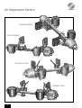
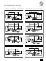
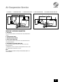
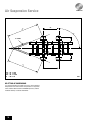
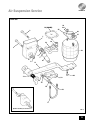
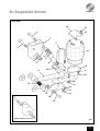
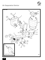
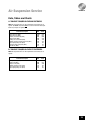
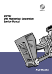
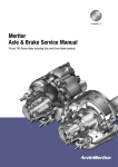
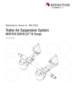
Meritor
Air Suspension Service Manual
Flexlite XL9000, Flexair FL9000 & FL11000
Air Suspension Service
FLEXAIR FL9000M
FLELITE XL9000
FLEXAIR FL11000
FLEXAIR FL9000
2
Air Suspension Service
INDEX
Section
Description
Page
THE MERITOR WARRANTY
4
THE SUSPENSION I/D PLATE
5
1
INTRODUCTION
6
2
TRACKING AND RE-ALIGNMENT
12
3
REPLACEMENT OF AIRSPRINGS
21
4
REPLACEMENT OF DAMPERS
22
5
REPLACEMENT OF AXLE
23
6
REPLACEMENT OF TRAILING ARMS
25
7
REPLACEMENT OF PIVOT BUSHES
26
8
SETTING OF HEIGHT VALVE
27
9
MAINTENANCE SCHEDULE
28
10
FAULT FINDING
30
3
Air Suspension Service
Meritor HVS Suspension Warranty
Warranty Procedure
1. MECHANICAL, FLEXAIR AND INDAIR SUSPENSIONS
24 MONTHS PARTS AND LABOUR
Should any MERITOR equipment fitted to your trailer become
unserviceable within the warranty period, contact the trailer
manufacturer or MERITOR Service Department who will advise on the
appropriate action.
2. FLEXAIR AND FLEXLITE UNITS ASSEMBLED WITH
AXLE BY MERITOR H.V.S.
36 MONTHS PARTS AND LABOUR
For full warranty terms and conditions see ‘Meritor Warranty
Terms and Conditions’ Publication No 4.84.1
Unless otherwise stated, Aftermarket components are warranted for 1
year, parts only, mechanical failure only.
A comprehensive network of original parts distributors and service
stations operate throughout Europe; this is supported internationally
with agents strategically placed around the world.
MERITOR H.V.S. reserve the right to make changes in specifications
shown herein or add improvements at any time without notice or
obligation.
PARTS SHOWN ARE MADE FROM DRAWINGS IN WHICH COPYRIGHT
SUBSISTS. THE MAKING OF COPIES OF ANY OF THESE PARTS IS
PROHIBITED.
Patents and applications of MERITOR H.V.S. Ltd that are specifically
relevant to air suspension systems:
Indair ride height adjustment, GB Patent No. 2165500. Shock
absorbers as restraints, GB Patent No. 2165501. Indair suspension,
GB Patent No. 2165195, CA Patent No. 1232302, DE Patent No.
3437393, NZ Patent No. 209838, US Patent No. 4593930. Deflation of
air suspension, GB Patent No. 2184405. Compact Indair, GB Patent
No. 2194761. Load distribution on air suspended vehicles, GB Patent
No. 2239222, EPO (BE, DE, DK, ES, FR, IT, NL) appn. 90314050, AU
Patent No. 646005, IE appn. 4530/90, NZ appn. 236519, PT appn.
96354, ZA Patent No. 90/10241. Suspensions for vehicles (long
stroke), EPO (AT, BE, DE, DK, FR, GB, IT, NL, SE) Patent No. 472309.
Vehicle tracking adjustment, GB Patent No. 2257670.
Loading/unloading of air suspended vehicles, EPO (BE, DE, ES, FR,
GB, IT, NL) appn. 92307639. Axle lift, GB appn. 9404557, PCT, EPO
(AT, BE, CH+LI, DE, ES, FR, GB, GR, IE, IT, LU, MC, NL, PT, SE, AU, LA,
NZ, US) appn. PCT/GB94/458.
© MERITOR HVS
The high quality assurance management systems applied by MERITOR
are endorsed with the awarding of ISO 9001, Lloyd’s Register Quality
Assurance.
4
Air Suspension Service
Identifying the Suspension Type
Suspensions leaving the MERITOR factory are fitted with an optional identification plate which contains all the information needed to ensure the
correct replacement parts are obtained.
The suspension type code includes the suspension model, ride height and tracking type as shown below
FL = Flexair
XL = Flexlite
F
X
L = Low Height
M = Dual Height
NB = Special Lightweight
D = Demount
L
9 = 9000
9L = 9000L
9NB = 9000NB
9M = 9000M
9HL = 9000HL
9i = 9000i
9H = 9000H
I = Integrated Cross Member
S = Self Steer
C = Command Steer
/
11 = 11000
11L = 11000L
11L = 11000L/150
11D = 11000D
11B = 11000B
11LB = 11000LB
}
/
Ride Height
e.g. 425
See Page 8
T = Tracking Fitted
The models of suspension are detailed in Section 1 of this manual.
Identifying the Serial Number
NOTE: The serial number is also carried by the axle and thus contains the brake lining code. This will be missing if a suspension is sold separately.
Build Month
Brake Lining Type
Order Number
Sequential Number
Build Year
NOMINAL CAPACITY
This is the capacity of the suspension before being matched to an axle.
COMBINED CAPACITY
This is the suspension capacity in use and will reflect the axle capacity and any other constraints.
5
Air Suspension Service
SECTION 1
Introduction
Meritor air suspensions are specifically designed to suit the MERITOR
range of axles. Modern technology and stringent testing have been
used to ensure the perfect match.
4. RAISE/LOWER FEATURE
With air suspensions it is possible to raise or lower the chassis to
facilitate loading at different dock heights.
MERITOR offers the Levelride II system to facilitate this requirement.
This is an MERITOR patented system that is a raise/lower device but
with an automatic reset facility triggered by application of the brakes.
The axle is mounted to flexible trailing arms using a cast steel seat
design. The arms are then mounted via rubber bushes, to a pair of
hanger brackets which are then welded to the chassis.
Upon the first brake application after using the raise/lower system, an
electrical signal is sent to the levelride unit that automatically resets
the trailer to its normal ride height. This system eliminates unnecessary
damage to the suspension that can occur if the trailer is driven in the
raised or lowered position.
At the rear of each trailing arm an airspring is located and the top of
the airspring fitted to the chassis.
5. AUTO DROP
Principle of Operation
When a lift axle is fitted, it is possible to fit a Meritor ELMS system that
enables the lift axle to automatically drop to its unlifted position when
the axle load exceeds a predetermined level.
The basic design of these units is of the flexible link (trailing arm) type.
During normal running in a straight line, striking bumps, potholes etc.,
superb ride characteristics are obtained due to the airsprings providing
a very low vertical suspension stiffness at the wheel. This ensures very
little shock is transmitted to the chassis/payload, thus minimising
structural damage or problems with goods.
During cornering manoeuvres, the axle tube acts as an anti-roll bar and
links each trailing arm. The majority of the compliance in roll comes
from the flexing of the trailing arms. Thus their design is a very careful
mix of strength and stiffness.
Careful design of the damper characteristics and positioning ensures a
high degree of damping required to gain the best possible performance
from an air suspension.
Modern dynamic analysis methods and testing were used to determine
such characteristics and positions.
Ancillary Equipment
1. SUSPENSION PIPING SYSTEMS
Pipework is available as complete pre-assembled kits for quick and
easy fitting. These are available in different versions depending on the
bogie specification, e.g. tandem, triaxle etc.
2. AXLE LIFT FACILITY
Axle lift facilities are available that will fit all suspension models. They
are capable of being retrofitted and in some cases not requiring any
welding.
3. AIRSPRING DUMP FACILITY
MERITOR recommends that all air suspended trailers without
raise/lower valves are fitted with this facility and a kit is available from
MERITOR.
When an air suspended trailer deflates, it can roll forward causing
bending and possible collapse of the landing legs. This is caused by
wheel rotation as the axle travels up.
A good solution to this problem is to fit rocking type landing legs.
6
6. ANTI-VACUUM SYSTEM
A requirement by Ferry companies is that air suspension systems are
exhausted before trailers are loaded aboard ship. Consequently there is
risk that during loading, the rubber side walls of the airspring can
become trapped between the internal rubber bump stop and piston and
become damaged.
This can be avoided by using an anti-vacuum system available from
MERITOR. A special quick release valve is fitted to each side of the
suspension which allows air into the system from atmosphere when
the airspring pressure falls below atmospheric pressure, thus
preventing the sidewalls from collapsing.
Meritor Patents
All MERITOR designs are registered, and copyright exists on all
drawings. In some instances, these designs are covered by one or
more patents. The following patents apply to the designs shown in this
manual:GB – 2 237 780
GB – 2 257 670
GB – 2 165 501
Air Suspension Service
A = RIDE HEIGHT
B = FRAME BRACKET HEIGHT
C = AIRSPRING PEDESTAL HEIGHT
FL9000
D = PIVOT TO AXLE CENTRE LINE
E = AXLE CENTRE TO AIRSRING CENTRE LINE
FL9000H
D
D
E
E
C
C
B
B
A
A
FL9000HL
FL9000L
D
D
E
E
C
C
A
A
B
B
FL9000HLL
FL9000NB
D
D
E
E
C
C
B
A
A
B
FL9000i
FL9000M
D
D
E
E
C
A
B
A
B
7
Air Suspension Service
A = RIDE HEIGHT
B = FRAME BRACKET HEIGHT
C = AIRSPRING PEDESTAL HEIGHT
XL9000
D = PIVOT TO AXLE CENTRE LINE
E = AXLE CENTRE TO AIRSRING CENTRE LINE
FL11000
D
D
E
E
C
C
B
A
XL9000L
A
B
FL11000L
D
E
D
E
C
C
A
B
A
B
XL9000H
FL11000L/150
D
E
D
E
C
C
A
A
B
XL9000HL
B
FL11000D
D
D
E
E
C
C
A
B
8
B
A
Air Suspension Service
A = RIDE HEIGHT
FL11000B
B = FRAME BRACKET HEIGHT
D
C = AIRSPRING PEDESTAL HEIGHT
D = PIVOT TO AXLE CENTRE LINE
E = AXLE CENTRE TO AIRSRING CENTRE LINE
FL11000LB
E
D
E
C
C
B
A
B
A
IMPORTANT SUSPENSION PARAMETERS
A. RIDE HEIGHT
This is the distance from the centre of the axle to the underside of the
chassis.
B. FRAME BRACKET HEIGHT
C. AIRSPRING PEDESTAL HEIGHT
D. PIVOT TO AXLE CENTRE LINE
This is the distance from the pivot centre in the frame bracket to the
centre of the axle tube.*
E. AXLE CENTRE TO AIRSPRING CENTRE LINE
This is the distance from the axle tube centre to the centre of the
airspring pedestal.*
* Both dimension ‘D’ and ‘E’ must be measured when the axle is in the
ride height position and dimension ‘A’ is set.
NOTE:
Refer to MERITOR installation drawings CD for allowable options and
recommendations.
9
Air Suspension Service
Flexair FL9000 Range Summary
OPTION
Ride Height
Capacity
Frame Centres (min-max)
Airspring Offset
Axle Travel (up/down)
FL9000
FL9000L
FL9000NB
FL9000H
375-550mm
200-375mm
310-425mm
500-550mm
9000 kg
9000 kg
9000 kg
9000 kg
1150-1400mm
1150-1400mm
1150-1400mm
1150-1400mm
30mm
30mm
30mm
30mm
100/110mm
100/95mm
80-90/110mm
100/110mm
Off road suitable
Yes
Yes
No
Yes
Suitable for drum
Yes
Yes
Yes
Yes
Suitable for disc
Yes*
No
Yes
Yes
Recommended axle lift
Cradle/Dual Side Lift
Cradle/Dual Side Lift
Cradle
Cradle/Dual Side Lift
Pivot Eye Tracking
(o=option s=standard)
o
o
o
o
FL9000HL
FL9000HLL
FL9000i
FL9000M
275-375mm
300-425
375-425mm
228-453mm
9000 kg
9000 kg
9000 kg
9000 kg
1150-1400mm
1150-1400mm
1150-1300mm
900-1200mm
30mm
0-30mm
30mm
0-95mm
100/110mm
85/205mm
100/110mm
65-230mm
Yes
No
Yes
Yes
Suitable for drum
Yes
Yes
Yes
Yes
Suitable for disc
Yes*
Yes
Yes
No
Recommended axle lift
Cradle/Dual Side Lift
TBA
Not available
Dual Side Lift
Pivot Eye Tracking
(o=option s=standard)
o
o
o
o
OPTION
Ride Height
Capacity
Frame Centres (min-max)
Airspring Offset
Axle Travel (up/down)
Off road suitable
Flexlite XL9000 Range Summary
OPTION
Ride Height
Capacity
Frame Centres (min-max)
Airspring Offset
Axle Travel (up/down)
XL9000
XL9000L
XL9000H
XL9000HL
375-450mm
200-250mm**
475-550mm
250-350mm
9000 kg
9000 kg
9000 kg
9000 kg
1150-1400mm**
1150-1400mm**
1150-1400mm**
1150-1400mm**
30mm
30mm
30mm
30mm
100/100mm
100/100mm
100/100mm
100/100mm
Off road suitable
No
No
No
No
Suitable for drum
Yes
Yes
Yes
Yes
Suitable for disc
Yes
No
Yes
No
Recommended axle lift
Centre
Centre
Centre
Centre
Pivot Eye Tracking
(o=option s=standard)
s
s
s
s
10
Air Suspension Service
Flexair FL11000 Range Summary
OPTION
Ride Height
Capacity
Frame Centres (min-max)
Airspring Offset
Axle Travel (up/down)
FL11000
FL11000L
FL11000-150
FL11000D
250-475mm
200-250mm
150mm
225-450mm
11000 kg
11000 kg
9000 kg
11000 kg
900-1200mm
900-1200mm
900-1200mm
900-1200mm
0-95mm
0-95mm
0-95mm
0-95mm
110/110mm
110/110mm
65/110mm
70/200mm
Off road suitable
Yes
Yes
No
Yes
Suitable for drum
Yes
Yes
Yes
Yes
Suitable for disc
Yes*
No
No
Yes
Recommended axle lift
Dual Side Lift
Dual Side Lift
N/A
Dual Side Lift
Pivot Eye Tracking
(o=option s=standard)
o
o
o
o
FL11000B
FL11000LB
500-725mm
225-450mm
11000 kg
11000 kg
900-1200mm
900-1200mm
0-95mm
0-95mm
OPTION
Ride Height
Capacity
Frame Centres (min-max)
Airspring Offset
Axle Travel (up/down)
95/100mm
95/100mm
Off road suitable
Yes
Yes
Suitable for drum
Yes
Yes
Suitable for disc
Yes
Yes
Recommended axle lift
Dual Side Lift
Dual Side Lift
Pivot Eye Tracking
(o=option s=standard)
o
o
* Ride height restrictions appy
** Can be reduced with restriction
Contact Meritor HVS for details
11
Air Suspension Service
SECTION 2
Re-aligning and Re-fitting of
Suspensions
This section provides details of how to re-align suspensions if their
settings are changed due to other work. It also discusses how to re-fit
a suspension should the case arise.
RE-ALIGNMENT (TRACKING)
All Flexair models are available when new with an optional, patented
pivot eye tracking facility. This device once used during the trailer build
is welded up and cannot be used for re-tracking.
Flexlite models feature as standard, a pivot eye tracking facility, which
is re-usable (non-welded).
If no tracking device is fitted the facility at the spring seat must be
used:The facility at the seat allows 8mm of movement by loosening the “U”
bolts.
To carry out this operation proceed as follows:
1. With the trailer unladen and no air in the system, support the chassis
on stands.
2. Remove the wheels.
3. If the “U” bolts (9) are not loose, unfasten them enough to enable
the axle to slide on the trailing arm and slide it as far rearward as
possible.
4. Using a tape measure, place one end on the side of the hub flange
and measure to the king pin. Rotate the hub forward and backwards to
ensure that the measurement is the maximum possible.
5. Slide the axle on each trailing arm until the measurements from
each hub to the kingpin (DR & DL) are equal to within ±2mm as shown
in Fig. 1.
6. When correct, remove each “U” bolt nut (17) and washer (18) shown
in fig. 3 and clean the bolt thread to remove dirt in turn.
Fit a new nut and washer.
Repeat the operation with all nuts. Tighten all nuts in a diagonal
sequence:With new “U” bolts see table on page 29.
If existing “U” bolts are used re-torque Flexair and Flexlite to 425 lbf
ft (575 Nm).
7. Replace wheels and remove supports from chassis.
If a drawbar unit is being worked upon, the procedure is the same
except the tracking measurements are to a different point.
12
Air Suspension Service
AR
BR
DR
Ø
LR
LL
DL
AL
AR
BR
LR
DR
Ø
= AL
= BL
= LL
= DL
= 90º
± 3mm
± 3mm
± 2mm
± 1,5mm
± 10'
BL
FIG. 1
With a standard semi-trailer the measurements are to the kingpin. With
a drawbar trailer they should be to the “A” frame towing eye.
Before the measurements are made, the “A” frame eye must be in its
central position to the chassis as shown in Fig. 2.
13
Air Suspension Service
AR
DR
Ø
LR
"A" FRAME
LL
DL
AL
AR
LR
DR
Ø
= AL
= LL
= DL
= 90º
± 3mm
± 2mm
± 1,5mm
± 10'
RE-FITTING OF SUSPENSIONS
It is recommended that if any doubt exists on the correct method of
fitting/removal of the frame brackets and pedestals of a suspension,
advice should be obtained from the MERITOR Engineering. A CD of
installation drawings is available from Meritor.
14
FIG. 2
Air Suspension Service
FLEXAIR 9000
24
23
19 (9000NB)
25
2
26
27
1
17
18
19
3
22
6
7
4
5
8
11
21
20
12
10
13
14
15
16
9
Optional tracking see section 2.
FIG. 3
15
Air Suspension Service
FLEXAIR 9000L
2
24
23
1
25
26
27
9
3
6
7
22
4
8
5
10
11
21
13
19
12
14
15
20
18
17
16
Optional tracking see section 2.
16
FIG. 4
Air Suspension Service
FLEXAIR 9000M
25
24
2
23
1
9
3
22
6
7
4
8
5
29
10
28
11
21
20
30
12
31
19
18
13
17
14
15
16
Optional tracking see section 2.
FIG.5
17
Air Suspension Service
FLEXLITE XL9000
24
23
25
1
26
2
27
3
17
15
16
8
6
15
22
7
18
19
13
14
4
5
21
10
20
9
FIG. 6
18
Air Suspension Service
FLEXAIR 11000
25
2
24
1
23
3
9
22
6
7
4
5
8
29
28
21
10
11
20
30
31
12
19
18
13
14
17
15
16
Optional tracking see section 2.
FIG. 7
19
Air Suspension Service
FLEXAIR 11000L
25
24
2
23
1
3
9
22
6
7
4
5
8
29
28
21
10
11
20
30
31
12
19
18
13
14
17
15
16
Optional tracking see section 2.
FIG. 8
20
Air Suspension Service
SECTION 3
General Maintenance
(Ref. Figs. 3, 4, 5 ,6, 7 & 8)
Removal and Refitting of Airsprings
REMOVAL
1. Ensure no air is in system.
REPLACEMENT
Flexair 9000, 9000L and Flexlite
1. With the airspring compressed, fit in position on the airspring
pedestal and fit the M22 nut (26) and washer (27) and new M12 nut
(24) and washer (23) and nip tight.
2. Pull the piston down and align the two required holes with the holes
in the trailing arms. Fit the two M12 bolts (20) and washers (21) and
nip up.
3. Torque the top M12 nut and four bottom M12 bolts to 50 lbf ft (70
Nm) and the M22 nut to 45 lbf ft (60 Nm).
2. Jack-up chassis and support on stands.
Flexair 9000, 9000L and Flexlite
3. Using a 27mm spanner remove the M22 air inlet pipe and the
securing nut (26) and washer (27) from the top of the airspring.
4. Using a 19mm spanner remove the M12 nut (24) and washer (23)
from the top of the airspring and the two M12 bolts (20) and washers
(21) securing the airspring piston to the trailing arm.
5. Remove the complete airspring by compressing it slightly if required.
Flexair 11000 and 11000L
6. Using a 27mm spanner remove the M22 air inlet pipe from the top of
the airspring.
Flexair 11000, 11000L and 9000M
4. Using a 19mm socket, bolt the lower airspring support plate (29) to
the airspring piston using the four M12 bolts (20) and washers (21)
located with the bolt heads in the counter bores in the offset plate.
Torque up to 50 lbf ft (70 Nm).
5. Ensure the offset plate is rotated to give the desired air inlet position
on the top of the airspring.
6. With the airspring compressed fit the airspring studs in position in
the airspring pedestal. Fit four new M12 nuts (24) and washers (23)
and nip tight.
7. Pull the piston/offset plate down and fit the two M16 studs (28)
through the holes in the trailing arm. Fit the two new nuts (31) and
washers (30) and nip tight.
7. Using a 19mm spanner remove the four M12 nuts (24) and washers
(23) from the top of the airspring.
8. Torque the M12 top nuts to 50 lbf ft (70 Nm).
8. Using a 24mm socket remove the two M16 nuts (31) and washers
(30) securing the airspring and offset plate (29) to the trailing arm and
remove the airspring by compressing it slightly if required.
10. Lower chassis off support stands.
9. Torque the M16 bottom nuts to 135 lbf ft (180 Nm).
NOTE: USE ONLY MERITOR GENUINE SPARE PARTS.
9. Using a 19mm socket, remove the four M12 bolts (20) and washers
(21) securing the offset plate (29) to the airspring piston.
21
Air Suspension Service
SECTION 4
Removal and Replacement of
Dampers – Flexair Models
REMOVAL
1. With the trailer in its normal ride height (unladen) using a 36mm
socket and ring spanner, remove the nuts (7 & 13) and washers (6 &
14) from the top and bottom damper bolts.
2. Withdraw both the upper and lower mounting bolts (2 & 16) and
remove the damper (8).
REPLACEMENT
1. Locate the top eye of the damper and fit the mounting bolt with a
flat washer under the head of the bolt and behind the nut. Ensure the
bolt head is inboard. Fit a new nut and washer.
2. Rotate the damper and slowly pull it to extend its length until the
lower eye aligns with the mounting holes in the axle seat.
Fit the lower mounting bolt, flat washers and new nut. Ensure the bolt
head is inboard.
3. Using a 36mm socket and ring spanner torque the two nuts to 370
lbf ft (500 Nm).
Removal and Replacement of
Dampers – Flexlite Models
REMOVAL
1. With the trailer in its normal ride height (unladen) using a 24mm
socket and ring spanner, remove the nuts (7 & 13) and washers (6 &
14) from the top and bottom damper bolts.
2. Withdraw both the upper and lower mounting bolts (2 & 16) with
their washers (15) and remove the damper (8).
REPLACEMENT
1. Locate the top eye of the damper and fit the mounting bolt with a
flat washer under the head of the bolt and behind the nut. Ensure the
bolt head is inboard. Fit a new nut and washer.
2. Rotate the damper and slowly pull it to extend its length until the
lower eye aligns with the mounting holes in the axle seat.
Fit the lower mounting bolt, flat washers and new nut. Ensure the bolt
head is inboard.
3. Using a 24mm socket and ring spanner torque the two nuts to 220
lbf ft (300 Nm).
22
Air Suspension Service
SECTION 5
Removal and Replacement of Axle
There are a number of ways of removing the axle depending on how
much of the suspension is to be dismantled. The following procedure
however, is recommended assuming the suspension is to be left in
place.
REMOVAL
REPLACEMENT
If the original axle is not to be refitted, the replacement must be
supplied and approved by MERITOR. The use of axles previously used
on other suspensions is prohibited. If in doubt contact the MERITOR
Engineering Applications Department for detailed recommendations.
1. Lift axle onto trolley jacks and rotate to ensure it is correctly
orientated.
2. For single axle trailers and rear axles of tandems and triaxles slide
the axle into position over/ under the rear of the suspension unit.
1. Ensure no air is left in the system.
For the front axle of a tandem and the centre or front axle on a triaxle
trailer:
2. If spring brakes are fitted they should be released and constrained
using a caging tool.
3. Slide the axle sideways into position and place the trailing arms eye
ends in position in the frame brackets (1).
3. DRUM BRAKE TRAILERS – Remove the split pins and clevis pins
securing the brake chambers to the slack adjuster levers.
4. Align the holes in the trailing arm bushes (12), apply a thin coat of
general purpose grease to the shank of the pivot bolts (3) ENSURE NO
GREASE IS ON THREADS. Fit the bolts and new washers (4) and nuts (5)
and tighten such that the arms can easily pivot.
3. DISC BRAKE TRAILERS – Remove brake pipes, leaving the chamber
attached to the caliper.
4. If the axle is used to locate the bottom of the arm, with the
suspension height control valve, remove the eye coupling on the
levelling valve arm from the pin on the axle.
5. Jack up the trailer and support it under the chassis to take the
weight of the axle to be removed.
6. Support the axle to be removed on stands such that a pump trolley
or similar device can be slid between them to lower the axle once it is
unbolted from the suspension.
7. Remove the wheels from the axle.
8. Using a 36mm spanner and socket, remove the nut (13) and washer
(14) from the lower damper bolt (16) and withdraw the bolt. Slacken the
top damper bolt nut (7) and pivot the damper upwards to clear the axle
and secure it to the chassis.
9. Remove the airspring as detailed in Section 3.
10. Ensuring the axle supports are safe and using a 36mm socket
remove the four “U” bolt nuts (17) and washers (18) from each side of
the suspension, remove the “U” bolt plate (19) and withdraw the “U”
bolts (9).
For single axle trailers and rear axles of tandems and triaxles proceed
as follows:
11. Using a 46mm spanner and socket, slacken the two main pivot bolt
nuts (5) just enough to allow the trailing arms to easily pivot. Swing the
arms off the axle leaving it supported on the stands.
12. Slide trolley jacks as required under the axle, jack them up to take
the weight off the stands. Remove the stands and lower the jacks. Pull
the axle clear backwards over/under the arms and clear of the trailer.
For the front axle of a tandem and the centre or front axle on a triaxle
trailer proceed as follows:
13. Using a 46mm spanner and socket, remove the two main pivot nuts
(5) and washers (4) and remove the bolts (3). Ensure the arms are
supported to prevent them dropping. The arms can now be removed.
14. Slide trolley jacks as required under the axle and take the axle
weight. Remove the axle stands and slide the axle out sideways.
Continue for all models as follows:
5. Position axle stands under the axle at a workable height and lower
the axle onto them ensuring the trailing arm (11) is above/below as
required.
6. Ensure the mating faces on the trailing arm (11), seat (10) and “U”
bolt plate (19) are clean and undamaged.
7. Lift/lower the trailing arm to the axle and locate into the spring
seats.
8. Fit the “U” bolts (9), top plates (19), and new “U” bolt nuts (17) and
washers (18) and nip up.
9. Refit the airspring piston to the trailing arm as described in section
3.
10. Re-track the suspension as detailed in section 2.
11. Torque up the “U” bolts using a 36mm socket in a diagonal
sequence:With new “U” bolts see table on page 29.
If existing “U” bolts are used re-torque Flexair and Flexlite to 425 lbf
ft (575 Nm).
IT IS IMPORTANT THEY ARE TORQUED UP EVENLY.
12. Lower/raise the axle and trailing arm until the hole in the lower
damper bush is aligned with the location hole in the seat/”U” bolt plate.
If the old damper bolts (16) are being re-used ensure they are clean
(especially the threads) and undamaged and apply a thin coat of
general purpose grease to the shank of the damper bolts, ENSURE NO
GREASE IS ON THREADS. Re-fit the bolts.
13. Fit new nuts (13) and washers (14) and nip up.
14. Lower/raise the axle and arms until the axle is in the ride height
position (see section 1). IT IS VERY IMPORTANT THAT THE DAMPER AND
PIVOT BOLTS ARE ONLY FULLY TIGHTENED WHEN THE AXLE IS IN THE
RIDE HEIGHT POSITION. Torque up the top and bottom damper bolts
using a 36mm spanner and socket and the pivot bolts using a 46mm
spanner and socket – Refer to torque tables on Page 29.
23
Air Suspension Service
15. DRUM BRAKE TRAILERS – Refit the brake chambers on the air
chamber brackets and secure using the original nuts if undamaged.
Ideally new nuts and washers should be used. Ensure nuts and
washers are clean.
15. DISC BRAKE TRAILERS – Reconnect the brake pipes.
16. Refit the clevis and split pins in the slack adjuster levers and
remove spring cages if spring brakes are fitted. Check the brake
adjustment as detailed in the MERITOR axle service manual.
17. Refit the road wheels and lower trailer chassis and axle off their
support stands.
24
Air Suspension Service
SECTION 6
Removal and Replacement of Trailing
Arms – Flexair and Flexlite Models
10. Lift/lower the axle until it is in its ride height position (see section 1)
and support.
11. Re-track the axle as detailed in section 2.
12. Tighten the “U” bolt nuts in a diagonal sequence – Refer to torque
tables on Page 29.
13. Tighten the pivot bolt – Refer to the torque table on page 29.
REMOVAL
1. Ensure no air is in the system.
14. Tighten the upper and lower damper bolts – Refer to the torque
table on page 29.
2. Jack up the trailer chassis and place support stands in a suitably
safe location.
15. Refit the wheel and lower the axle and trailer chassis off their
support stands.
3. Support the axle and remove the road wheel off the axle side from
which the arm is to be removed. This allows access to the “U” bolts
(9).
4. Using a 36mm (24mm for XL) spanner and socket, remove the nut
(13) and washer (14) from the lower damper bolt nut (16) and withdraw
the bolt. Slacken the top damper bolt nut (7) and pivot the damper
upwards to clear the axle and secure it to the chassis.
5. Using a 36mm (24mm for XL) socket remove the four “U” bolt nuts
(17) and washers (18) and withdraw the “U” bolts. Remove the “U” bolt
plate (19).
6. Un-fasten the base of the airspring (22) as detailed in section 3.
7. Using a 46mm (30mm for XL) spanner and socket remove the pivot
bolt nut (5) and washer (4) and withdraw the pivot bolt (3). Care must
be taken to support the trailing arm (11) during this operation since it
may immediately drop down from the frame bracket (1). The arm can
now be removed.
REFITTING
1. Ensure that the inner faces of the frame bracket wear washers (28)
are tacked to the frame bracket and are clean and undamaged. Apply a
coating of grease to all faces and bores.
2. Check that the bore in the trailing arm bush (12) is clean and apply a
thin coating of general purpose grease.
3. Place the trailing arm (11) in position under the frame bracket and
lift the eye end into position and align the holes.
4. Ensure that pivot bolt (3) is clean and undamaged (especially if the
original bolt is to be refitted) and apply a thin coat of grease to the
shank. ENSURE NO GREASE IS LEFT ON THE THREADS.
5. Fit the bolts and new nuts (5) and washers (4) and tighten (not fully
at this stage) such that the arms can still rotate easily.
6. Ensure that the mating faces between the spring seat (10), “U” bolt
plate (19) and arm are clean and locate the arm in the seat ensuring
spacer plates are in position.
7. Clean the “U” bolt threads (9) and ensure they are not damaged and
fit the bolts, “U” bolt plates and new nuts (17) and washers (18). Nip
the nuts up but do not fully tighten.
8. Refit the base of the airspring (22) as detailed in section 3.
9. Check that the lower damper bolt (16) is clean and un-damaged,
apply a thin coat of general purpose grease. ENSURE NO GREASE IS
LEFT ON THE THREADS. Align the bolt with the hole in the spring
seat/”U” bolt plate and fit the bolt and a new nut (13) and washer (14).
25
Air Suspension Service
SECTION 7
Replacement of Pivot Bushes (12)
1. Follow the procedure in section 6 to remove the trailing arm in
question then proceed as follows:
2. Using MERITOR service tool part number 21215793 for Flexair
Models or part number 21219080 for Flexlite Models remove the old
bush.
3. Fit the new bush using the same service tool lubricating the rubber
prior to fitting with soft soap or Applied Chemicals Ltd. EP pressing
lubricant grade 1-630. Ensure when fitting the bush it is inserted
centrally into the spring eye end.
4. Refit the trailing arm following the procedure in section 6.
26
Air Suspension Service
trailer builder and is shown on the axle and suspension I/D plates.
SECTION 8
Setting Suspension Height Control
Valve
This is an area which is probably most unfamiliar to the trailer operator
and the one which will cause most problems if the following
parameters are not adhered to. Too high a ride height can cause more
roll motion too low means that there will be loss of axle travel
(contacting bump stop) during arduous use.
Parameters for setting ride height:
1. The trailer should be on level ground.
2. It should preferably be connected to the tractor unit to be used and
in a straight line with the unit, or set at the correct kingpin height.
3. All the trailer brakes should be off.
4. There should be an air supply of at least 6.5 bar.
5. The trailer should preferably be unladen or the load evenly
distributed laterally across the trailer.
6. If the trailer has been running it should be given at least 10 minutes
to “settle down”.
7. The valve should be set on increasing height as there is a “dead
band” in the actuating stroke of the valve.
8. The ride height must be set on the axle which has the levelling
valve.
9. If the trailer is fitted with a lift axle this should be in the down
position.
If the ride height is found to require resetting the following procedure
should be followed.
Lengthen or shorten the linkage rods which connect the levelling valve
arm to the axle (giving a proportional increase or decrease in the ride
height) by slackening the two cheesehead screws which pinch the
rubber eye ends onto the drop bar and pulling the bar in or out of the
rubber. If there is insufficient adjustment i.e. the bar is in danger of
coming out of the rubber, then further adjustment can be gained by
slackening the bolts holding the levelling valve to the bracket and
repositioning the valve within the holes. Bending of the levelling valve
actuating arm is not recommended.
If the ride height is found to be above the recommended setting, the
height should first be dropped below the required setting and then
increased back to the nominal ride height, thus avoiding the “dead
band” in the actuating stroke of the valve. This can be done by
shortening the linkage rod and bleeding air from the suspension by
slackening the air pressure connection on top of the airsprings. This
method also applies to situations where the ride has accidentally been
taken above the recommended setting.
NOTE: Some care is needed when checking the ride height as a false
reading may be obtained after tipping a load etc. The levelling valve
emits and exhausts air very slowly, so time should be allowed for it to
react once adjusted.
The valve emits air slightly faster than it exhausts. This is so that large
volumes of air are not constantly bled off during normal suspension
travel but still allowing a relatively quick reaction to an increase in load
or when the trailer is being brought up to operating height from flat.
FL9000M: The FL9000M suspension runs at two ride heights (228mm
and 253mm), refer to trailer builder for piping instructions.
Levelling
Valve Arm
Checking
Dimension
Slacken screws to
adjust height
Connecting
Linkage
Ride Height – 63.5mm = Checking Dimension
The ride height is the distance between the centre line of the axle and
underside of the frame. Subtracting 63.5mm, half the axle tube
diameter, from the ride height gives a simple checking dimension from
the underside of the frame to the top of the axle tube.
Once an initial setting of the ride height has been made it should be
checked by measuring from the top of the axle tube to the underside of
the trailer frame, and comparing with the nominal ride height less
63.5mm (tube radius). The nominal ride height is specified by the
27
Air Suspension Service
SECTION 9
Maintenance Schedule
BEFORE ENTERING SERVICE
IF THE OPERATOR IS IN ANY DOUBT ABOUT THE SAFETY OF THE
VEHICLE HE SHOULD NOT OPERATE IT AND SEEK QUALIFIED ADVICE.
Check the suspension and brake systems operate correctly.
Check the suspension air system for leaks by charging the system with
air and testing all joints and fittings using soapy water.
Ensure the suspension ride height is correctly set by referring to section
8.
If an axle lift system is fitted, operate the lift system to check it
operates correctly and observe the extra lift cylinders attached to the
levelling valve arms to ensure they function.
Carry out a visual inspection of all suspension and brake system pipe
work to ensure no possibility of fouling or rubbing against each other or
other components.
Check the brake system operates correctly.
Check the operation of all optional equipment fitted. If any doubt or
problems arise refer to the appropriate service manual or seek qualified
advice.
AFTER FIRST 1000 KM
Check all fastener torques according to the torque tables on Page 29.
Examine all valves and air hose joints for leaks or signs of pipework
rubbing against the chassis or suspension components.
Check the suspension ride height as explained in section 8.
Inspect the dampers for evidence of oil leaks.
If an axle lift is fitted, check that it is functioning correctly.
Check the operation of all optional equipment and test for air leaks on
air system equipment. Individual service manuals should be referred to
if required.
AFTER FIRST 10000 KM AND SUBSEQUENT 10,000 KM INTERVALS
Inspect the dampers for evidence of oil leaks and inspect the damper
bushes for signs of rubber extrusion or damage.
Check the airsprings for signs of leakage and examine the rubber
bellows for signs of damage from road debris.
Check all pipe joints for signs of leakage and ensure that no valves are
fouled with road dirt such that their operation may be impaired. This is
especially relevant to the levelling valve. This is particularly important if
the trailer has been operated in a harsh environment e.g. coal, dust,
quarries etc.
If an axle lift is fitted, check it is operating correctly.
Check the operation of all optional equipment and test for air leaks on
air system equipment. Individual service manuals should be referred to
if required.
Examine tyres for uneven wear. If there is any present check the pivot
bushes for damage and re-check the axle alignment as detailed in
section 2.
28
If damage is found then the trailing arms should be removed as
detailed in section 6 and replacement of the bush and possibly the
wear plates is advised. Failure to do so may result in tyre wear or
structural damage.
Check all fastener torques and tighten where required according to the
values in the table in this section.
If an axle lift assembly is fitted ensure it is operating correctly. Check
the extra lift cylinders are operating as the axle is being raised.
EVERY 100,000 KM
Check the dampers for oil leaks along their body. Lever between the
damper eye ends (top and bottom) and close bracketry to ensure no
excessive lateral movement exists indicating bush failure or loose bolts.
If the bushes are damaged they should be replaced.
Check the airsprings for air leaks and signs of damage especially to the
rubber bellows. Details of replacing them can be found in section 3.
Uncouple the levelling valve arm/axle rubber joint and raise and lower
the arm to check that the valve is passing air in and out of the
suspension system.
Check the pressure protection valve by draining the brake and
suspension air tanks and couple up an air pressure gauge to each tank.
With an air supply of 6.5 bar, recharge the tanks. The brake tank
pressure should reach 5 bar minimum before the suspension tank
begins to charge.
Clean under the suspension inside the hanger brackets and around the
trailing arm pivots. Check between the wear plates welded to the inside
faces of the hanger brackets and the trailing arms for signs of
excessive wear or damage to the rubber pivot bushes.
All torques must be within ±5% of stated values.
Air Suspension Service
Data, Tables and Charts
A. TABLE OF TORQUES ON FLEXAIR FASTENERS
NOTE: All suspensions to be at ride height before fastener torques are
applied. (FL9000M suspension must be set at the maximum ride height
before any torques are applied).
Fastener Description
Main pivot nuts (M30)
Main pivot nuts (M24)
U bolts (and centre lift) (M24)
Damper bolts (M24)
Trailing arm centre bolts (M16)
Bottom airspring support plate studs (M16)
Top airspring fixing nuts (M12)
Airspring piston fixing bolts (M12)
Axle lift nut (M10)
Torque
Nm
lbf ft
1100
800
680
500
230
180
70
70
36
810
585
500
370
170
135
50
50
27
B. TABLE OF TORQUES ON FLEXLITE FASTENERS
NOTE: All suspensions to be at ride height before fastener torques are
applied.
Fastener Description
Main pivot nuts (M24)
U bolt nuts (M24)
Damper nuts (M16)
Bottom airspring screws (M12)
Top airspring fixing nuts (M22)
Top airspring fixing nuts (M12)
Torque
Nm
lbf ft
800
800
300
70
60
70
585
585
220
50
45
50
29
Air Suspension Service
SECTION 10
● If vehicle is load sensed, check that a shuttle valve is fitted
to prevent cross coupling. Fit if necessary
Flexair Fault Finding
SUSPENSION AIR RELATED PROBLEMS
This section is intended to give a guide to the trailer operator to enable
him to assess problems. The range of problems and suggested causes
and cures are by no means complete but are intended to provide a
solution to the most commonly encountered difficulties.
If suspension will not inflate:
NOTE: IF THE OPERATOR IS IN DOUBT ABOUT THE SAFETY OF THE
VEHICLE HE SHOULD NOT OPERATE IT, AND SHOULD IMMEDIATELY SEEK
QUALIFIED ADVICE FROM MERITOR.
● Ensure the suspension air reservoir pressure is at least
6.5 bar
How to use this section.
The faults are listed under five main headings, namely
1. BRAKING PROBLEMS
2. TYRE WEAR
3. EXCESSIVE ROLL
4. SUSPENSION AIR RELATED PROBLEMS
5. AXLE LIFT RELATED PROBLEMS
Listed under each of these headings are the likely specific problems,
each followed by a check procedure which should highlight the cause
of the problem. If the problem cannot be solved after working through
the relevant check list, then further information should be obtained
from MERITOR.
BRAKE FAULTS
● Check that the levelling valve is connected to the axle
● Ensure the brake air reservoir pressure is more than 6.5 bar
● Check the setting of the pressure protection valve and
clean the air filter
● Check the axle load is not greater than the available
pressure
● Check all pipework and fittings for leaks using soapy water
● Check the airsprings for leaks using soapy water
● Check levelling valve for leakage at the exhaust port, and if
necessary replace valve
If suspension is deflating:
● Check all pipework and fittings for leaks using soapy water
● Check the airsprings for leaks using soapy water
● Check levelling valve for leakage at the exhaust port, and if
necessary replace the valve
If brakes are not functioning correctly:
● Check that there is at least 6.5 bar at coupling head
● Check slack adjusters are correctly adjusted
● Ensure all brake system valves are functioning correctly
IF PROBLEM PERSISTS SEE MERITOR AXLE AND BRAKE SERVICE
MANUALS FOR FULL BRAKE SERVICE PROCEDURE.
TYRE WEAR
If tyre wear is excessive:
● Check axle alignment is correct
● Check wheels are parallel (i.e. zero camber and toe in/out)
● Inspect parabolic trailing arm pivot bushes for damage, and replace
if necessary
● Check shock absorber for oil leaks
● Inspect shock absorber bushes for damage
● Ensure ride height is set correctly
EXCESSIVE ROLL
If trailer is rolling excessively:
● Check shock absorbers for oil leaks
● Inspect shock absorber bushes for damage
● Ensure U bolts are correctly torqued
● Ensure ride height is set correctly
30
AXLE LIFT RELATED PROBLEMS
If lift will not operate:
● Work through check procedure for main suspension
airsprings not inflating
● Check that the lift valve is correctly installed and piped.
Replace valve if faulty
If main suspension airsprings fail to deflate when lift is operated:
● Check the Humphrey valve is correctly installed
● If main airspring pressure is lower than available pressure,
replace Humphrey valves
● Work through check procedure for main suspension
airsprings not inflating
If lift is insufficient:
● Check the extra lift cylinders are operating correctly
● Ensure trailer ride height is set correctly
For further information contact MERITOR.
Air Suspension Service
31
Meritor HVS Limited
Commercial Vehicle Systems
Rackery Lane, Llay
Wrexham LL12 0PB
U.K.
Telephone: +44 (0)1978 852141
Fax: +44 (0)1978 856173
Meritor HVS (Mitry-Mory) S.A.
Commercial Vehicle Systems
Z.I. du Moulin à Vent
9 rue des Frères Lumière
77290 Mitry-Mory
France
Telephone: +33 (0)1 64.27.44.61
Fax: +33 (0)1 64.27.30.45
Meritor HVS (Verona) s.r.l.
Commercial Vehicle Systems
Via Monte Fiorino, 23
37057 San Giovanni Lupatoto
Verona
Italy
Telephone: +39 045 8750399
Fax: +39 045 8750640 / 8750513
Meritor HVS (Barcelona) S.A.
Commercial Vehicle Systems
Ctra. Granollers - Sabadell Km. 13,3
Poligono Argelagues
08185 Lliçà de Vall
Spain
Telephone: +34 (9)3 843 95 68
Fax: +34 (9)3 843 83 59
ArvinMeritor Inc.
World Headquarters
2135 West Maple Road
Troy, Michigan 48084
U.S.A.
Telephone: +1 248 435 1000
ArvinMeritor
Commercial Vehicle Aftermarket AG
Neugutstrasse 89
8600 Dübendorf
Switzerland
Telephone: +41 (0)1 824 8200
Fax: +41 (0)1 824 8264
ArvinMeritor
Commercial Vehicle Systems
Postbus 255
5700AG Helmond
Churchilllaan 204A
5705BK Helmond
Holland
Telephone: +31 (0)492 535805
Fax: +31 (0)492 547175
ArvinMeritor South Africa
Commercial Vehicle Systems
Telephone: +27 (0) 83 602 1603
For further information contact
Meritor HVS Limited
Commercial Vehicle Systems
Rackery Lane, Llay
Wrexham LL12 0PB
U.K.
Telephone: +44 (0)1978 852141
Fax: +44 (0)1978 856173
www.arvinmeritor.com
© Copyright 2001
Meritor Automotive
All rights Reserved
Publication 4.91.1
Descriptions and specifications were in
effect at the time of publication and are
subject to change without notice or
liability. Meritor reserve the right to make
design improvements, change or
discontinue parts at any time.