1
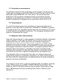
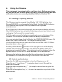
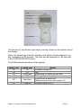
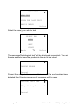
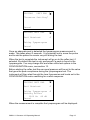
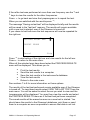
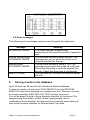
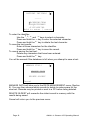
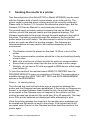
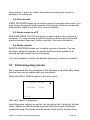
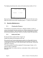
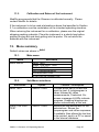
MedRx Otowave 102 Hand Held Portable Tympanometer Operating Manual (Applies from serial number 36640 onwards) MedRx Inc 1200 Starkey Rd., #105, Largo, FL 33771 USA [email protected] For supply in US only Caution: Federal Law restricts this device to sale by or on the order of a licenced medical professional. CONTENTS 1. Introduction...................................................................................... 3 1.1. Intended applications ........................................................................ 3 1.2. Features ............................................................................................ 3 1.3. Unpacking ......................................................................................... 3 1.4. Standard contents ............................................................................. 4 1.5. Optional accessories ......................................................................... 4 1.6. Warranty card .................................................................................... 4 1.7. Guarantee.......................................................................................... 4 1.8. Acknowledgements ........................................................................... 5 2. Important Safety Instructions......................................................... 5 2.1. Precautions ....................................................................................... 5 2.2. Electromagnetic compatibility considerations.................................... 6 3. Principles of Operation ................................................................... 6 3.1. Compliance measurement................................................................. 7 3.2. Tympanogram ................................................................................... 7 3.3. Stapedial reflex measurement........................................................... 7 4. Using the Otowave .......................................................................... 8 4.1. Installing & replacing batteries .......................................................... 8 4.2. Controls and indicators...................................................................... 8 4.3. The probe ........................................................................................ 10 4.4. Start-up and menu displays............................................................. 10 5. Taking measurements................................................................... 11 5.1. Prior to testing and Ambient conditions ........................................... 11 5.2. Performing a test ............................................................................. 11 5.3. Ear seal check ................................................................................. 16 5.4. Reflex auto stop .............................................................................. 16 5.5. Error messages ............................................................................... 17 6. Saving results in the database..................................................... 17 7. Sending the results to a printer ................................................... 19 8. Sending the results to a computer .............................................. 20 9. Data management.......................................................................... 21 9.1. List records ...................................................................................... 22 9.2. Print records .................................................................................... 23 9.3. Send records to a PC ...................................................................... 23 9.4. Delete records ................................................................................. 23 10. Performing daily checks ............................................................... 23 11. Routine Maintenance .................................................................... 24 11.1. Cleaning the Otowave ..................................................................... 24 11.2. Eartip and Probe.............................................................................. 24 11.3. Calibration and Return of the Instrument......................................... 25 12. Menu summary .............................................................................. 25 12.1. Main menu....................................................................................... 25 12.2. Sub-Menu selections ....................................................................... 25 OM001-11 Otowave 102 Operating Manual Page 1 13. 14. 14.1. 14.2. 14.3. 15. 16. Page 2 Error messages ............................................................................. 28 Technical Specification................................................................. 30 Performance .................................................................................... 30 Equipment classification .................................................................. 33 Symbols........................................................................................... 33 Ordering Consumables and Accessories ................................... 34 EMC Guidance & Manufacturer’s Declaration ............................ 35 OM001-11 Otowave 102 Operating Manual 1. Introduction Thank you for purchasing a MedRx Otowave 102, a hand held, portable tympanometer that will give many years of reliable service if treated with care. This operating manual covers product variants 102-1 & 102-4. 1.1. Intended applications The MedRx Otowave is designed for use by audiologists, general practitioners, hearing aid dispensers and child health professionals. The instrument performs two types of measurement: Tympanometry is used to measure the compliance of the tympanic membrane and middle ear at a fixed frequency over a range of pressures. Reflex tests are used to measure stapedial reflexes. The Otowave measures ipsilateral reflexes and, when selected, reflex measurement is automatically carried out after a tympanogram is taken. 1.2. Features Automatic measurement of ear canal volume, tympanic compliance peak, placement of the peak and the gradient. Automatic detection of stapedial reflexes. Up to 30, dual-ear patient tests can be stored in non-volatile memory. Configurable settings for user preferences, held in non-volatile memory. Printout via an infrared link to one of two thermal printers that may be selected by the user. Transfer to Windows XP via an infrared IrDA link for storage and display using NOAH. 1.3. Unpacking Please check the contents of the shipping carton against the delivery note to make sure that all items ordered have been included. If anything is missing, please contact the distributor who supplied your tympanometer or MedRx if you purchased direct. Please retain the carton and packaging as the tympanometer will need calibrating on an annual basis and should be returned to MedRx in its original shipping carton. OM001-11 Otowave 102 Operating Manual Page 3 1.4. Standard contents MedRx Otowave 102 Tympanometer 4 x 1.5V ‘AA’ Batteries (UK only) Test cavity Set of disposable ear-tips Carrying case Operating manual Calibration certificate Warranty card 1.5. Optional accessories Portable thermal printer NOAH3 impedance module Infra-red USB Adapter Additional sets of ear tips Additional rolls of thermal printer paper If the thermal printer has been purchased it should be charged for a period of 8 hours before being used. Refer to the printer instructions for further details. 1.6. Warranty card Please complete the enclosed warranty registration card and return it to MedRx. This will enable us to register your purchase, help with your enquiries and provide technical support. 1.7. Guarantee All MedRx instruments are guaranteed against faulty materials and manufacture. The instrument will be repaired free of charge for a period of one year from the date of dispatch if returned, carriage paid, to the MedRx service department. Return carriage is free of charge for customers in the UK and chargeable for overseas customers. Important Note The following exceptions apply: The pressure pump and transducers may go out of calibration due to rough handling or impact (dropping) Page 4 OM001-11 Otowave 102 Operating Manual The lifetime of probe, probe seals and eartips is dependent upon conditions of use. These parts are only guaranteed against faulty materials or manufacture. 1.8. Acknowledgements Windows and Windows XP are registered trademarks of Microsoft Corporation. 2. Important Safety Instructions The Otowave 102 instrument must be used only by practitioners qualified to perform tympanometric tests. It is intended for use as a screening and diagnostic tool, however no surgical or medical procedure should be undertaken solely on the basis of results obtained from the instrument. 2.1. Precautions READ THIS OPERATING MANUAL BEFORE ATTEMPTING TO USE THE INSTRUMENT Use the instrument only as described in this manual. Use the recommended batteries, do not mix battery types or old and new batteries. Remove batteries from the instrument if the instrument is not going to be used for more than a month. Always set the BATTERY TYPE in the CONFIGURATION MENU to show which batteries are fitted. See section 12. Before the first use of the instrument each day, or if suspect or inconsistent results are apparent, the checks specified in Section 10 must be carried out. If these do not give the results specified, the instrument must not be used. Never insert the probe into a patient’s ear canal without a suitable ear tip fitted to the probe. Use only the recommended disposable ear tips (see Section 15 for details). These are for single use only - that is, each ear tip is intended to be used once only for a single ear for a single patient. Do not reuse ear tips as this will pose the risk of ear-to-ear or patient-to-patient cross infection. OM001-11 Otowave 102 Operating Manual Page 5 Do not immerse the unit in any fluids. See section 11 of this manual for the proper cleaning procedure. Do not use the instrument in the presence of a flammable anaesthetic mixture. Thermal paper printouts fade with exposure to light or heat. Photocopying the patient record test results will ensure a more permanent record is kept. Do not drop or otherwise impact this instrument. If the instrument is dropped or damaged, return it to the manufacturer for repair and/or calibration. Do not use the instrument if any damage is suspected. The instrument must be stored and used indoors within the specified temperature, pressure and humidity ranges, see section 14. As with all instruments of this nature the measurements taken will be influenced by significant changes in altitude & pressure. The Otowave 102 tympanometer must be re-calibrated if it is to be used at elevations greater than 1000m above mean sea level. Do not attempt to open or service the instrument. Return the instrument to the manufacturer or distributor for all servicing requirements. Opening the instrument will void the warranty. 2.2. Electromagnetic compatibility considerations Portable and mobile RF communications equipment can affect medical electrical equipment. The Otowave 102 has been tested to the standards required for Electromagnetic Compatibility for medical equipment of this nature. The instrument should not be operated in the presence of high electromagnetic fields, for example those from high-powered medical devices or RF communications equipment. The instrument should not be used adjacent to or stacked with other equipment. Refer to Section 16. 3. Principles of Operation Please note: This operating manual is not intended as a training manual for tympanometry. The reader should consult standard audiology texts for the theory and application of the screening tests provided by this instrument. Page 6 OM001-11 Otowave 102 Operating Manual 3.1. Compliance measurement The Otowave measures the compliance of the tympanic membrane and middle ear by playing a continuous 226Hz tone into the ear canal at a level calibrated to give 85dB SPL into a 2ml cavity. The sound level this produces in the ear canal is measured using a microphone and the compliance calculated from the result. In line with normal audiometric practice compliance is displayed as an equivalent volume of air in ml. 3.2. Tympanogram To record the tympanogram the compliance is measured while the air pressure in the ear canal is varied from +200daPa to -400daPa by means of a small pump. The compliance peaks when the air pressure is the same on both sides of the tympanic membrane. The changing compliance with pressure is displayed as a graph. 3.3. Stapedial reflex measurement Using the same principle it is also possible to establish whether a Stapedial reflex is present. In this case, the 226Hz tone is used to measure the compliance of the ear, while a short tone at a different frequency is presented (the reflex stimulus). The sound pressure level (SPL) of this stimulus is increased in steps until the stapedial muscles respond causing the tympanic membrane to become stiffer, or a preset maximum SPL is reached. When the change in compliance exceeds a predetermined threshold this constitutes a reflex and the change in compliance at that level when the stimulus is applied is displayed as a plot against time. The stapedial reflex is measured at the static ear canal pressure that produces the maximum membrane compliance, so reflex measurements are taken after the tympanogram is measured when the peak compliance pressure has been established. The Otowave model 102-1 measures stapedial reflex at 1000Hz, while the model 102-4 measures at 500Hz, 1000Hz, 2000Hz and 4000Hz. The maximum SPL for the reflex stimulus may be preset, along with the step size in dB between the three preceding lower levels of stimulus (see Section 5). OM001-11 Otowave 102 Operating Manual Page 7 4. Using the Otowave This instrument is equipped with a real-time clock. Before use, please set the date & time to local values in order to ensure that test data and calibration status are correctly identified. Refer to Section 12.2. 4.1. Installing & replacing batteries The Otowave may be powered from Alkaline ‘AA’ / LR6 batteries (e.g. Duracell MN1500) or rechargeable Nickel-Metal Hydride (NiMH) batteries. Four batteries are required. Use only batteries from reputable manufacturers. If the Otowave is to be used infrequently we recommend alkaline cells are fitted. NiMH batteries have a high self-discharge rate and are likely to need recharging if left unused for several weeks. To fit the cells remove the battery compartment cover on the base of the Otowave. Fit the cells as indicated inside the battery compartment. You must set which type of cell is fitted in the CONFIGURATION menu. By default this is set to ALKALINE. To change the setting select CONFIGURATION from the main menu and scroll to BATTERY TYPE as described later in this manual. A battery state indicator is shown in the top right corner of the display (except when showing test results). This shows the battery state as a progressively emptying battery. The batteries should be replaced when the symbol has an ! in front of it, or when advised to do so at switch-on. Removing the batteries does not affect the configuration, the contents of the database, the calibration settings or the results of the last test. 4.2. Controls and indicators Press the On / Off key momentarily to turn the Otowave on or off. Press the up ( ) and down ( ) navigation keys to scroll through the menus or set values. Press the right navigation key ( ) to accept a menu choice or go to the next step. Press the left navigation key ( ) to cancel an operation or go back to the previous step. Page 8 OM001-11 Otowave 102 Operating Manual The function of the left and right keys is usually shown on the bottom line of the display. When not performing a test the Otowave will switch off automatically if no key is pressed for 90 seconds. This time can be extended to 180 seconds in the CONFIGURATION menu. The LEDs indicate the status of the system: Green LED Off On Off Slow flash Yellow LED Off Off Slow flash Off Off Fast flash On Flickering Status Otowave turned off Idle Attempting to obtain an ear seal Taking a measurement Pump error at switch-on. Measurement error, see section 12. Sending data to a PC OM001-11 Otowave 102 Operating Manual Page 9 4.3. The probe The small holes through the Otowave probe tip must be kept clear. If these become blocked a warning message will be displayed. The tip must be removed and cleaned or replaced. To remove the tip, unscrew the nose cone and pull the tip off the probe boss. A small seal will be found in the base of the probe tip. This should be examined and replaced if it is damaged. When replacing the tip, ensure that the seal is correctly inserted with its flat aligned with the flat on the probe tip. Push the probe tip over the boss and replace the nose cone. Make sure that the nose cone is screwed home firmly but do not over-tighten. Do not use any tools to tighten the nose cone. After replacing the tip a Daily Check should be carried out, as described in section 10. 4.4. Start-up and menu displays When the Otowave is turned on the start-up screen is shown while internal tests are performed and the pump is initialised. When the start up sequence is complete the MAIN MENU is displayed: Page 10 OM001-11 Otowave 102 Operating Manual MAIN MENU NEW TEST VIEW THE LAST TEST DAILY CHECK Select Menu items and instructions are shown in upper case text. Information and error messages are generally in lower case. The menus are summarised in section 12. 5. Taking measurements Safety Note: The probe tip must be fitted with an ear tip before it is presented to a patient’s ear canal. The ear tip must be fitted completely to the probe tip and must not occlude any of the four holes in the probe tip. The ear tip is chosen to suit the patient’s ear and provide a comfortable pressure seal. 5.1. Prior to testing and Ambient conditions The health care professional should perform a thorough otoscopic examination to establish that the condition of the ear is suitable for the test options selected. Tympanometric and reflex testing should always be performed in a quiet room or in an acoustic booth. 5.2. Performing a test A typical tympanogram measurement and reflex test is carried out as follows. From the MAIN MENU select NEW TEST: OM001-11 Otowave 102 Operating Manual Page 11 MAIN MENU NEW TEST VIEW THE LAST TEST DAILY CHECK Select Select the ear(s) you wish to test: SELECT EAR BOTH LEFT Back RIGHT Select The message “Deleting last test” will be displayed momentarily. You will then be asked to insert the probe into the ear to be tested: TESTING LEFT EAR INSERT PROBE Cancel Present the ear tip to the ear and obtain a seal. If a good seal has been detected the following sequence of messages will be seen TESTING LEFT EAR “Equalising Pressure” Cancel Page 12 OM001-11 Otowave 102 Operating Manual TESTING LEFT EAR “Pressure Settling” Cancel TESTING LEFT EAR Seal Obtained Taking Tympanogram Cancel Once an adequate seal is detected the tympanogram measurement is made. This takes about 3 seconds. It is important not to move the probe and to ask the patient to remain very still during the test. When the test is complete the instrument will go on to the reflex test, if selected. By default this test is only performed if a peak is found in the tympanogram. You may change this and other reflex test options in the CONFIGURATION menu, see section 12. Before starting the reflex test the ear canal pressure will be set to the value that gave the peak compliance during the tympanogram test. The instrument will then step through the tone frequencies and levels set in the CONFIGURATION menu searching for a reflex response: TESTING LEFT EAR Seal Obtained Taking Tympanogram Seeking Reflex 1000 Hz 80 dB Cancel When the measurement is complete the tympanogram will be displayed: OM001-11 Otowave 102 Operating Manual Page 13 The display shows: The peak compliance, in ml (Pk) The pressure which gave the peak compliance in daPa The Gradient, in daPa (Gr) The Ear Canal Volume (ECV) in ml measured at 200 daPa. A plot of compliance against pressure. Review the tympanogram to make sure that the peak compliance point selected by the Otowave is correct. If you are not satisfied you may select another peak using the and keys. The figures displayed will change to reflect the peak you select. To repeat the test, press . When you are satisfied with the tympanogram press . If the reflex test was carried out the results will now be displayed: The display shows: The frequency of the measurement. “PASS” if a reflex was found, else “NR” (No Response). The level of the tone for which a reflex was first found. A plot of compliance against time. Page 14 OM001-11 Otowave 102 Operating Manual If the reflex test was performed at more than one frequency use the and keys to view the results for the other frequencies. Press to go back and view the tympanogram or to repeat the test. When you are satisfied with the results press . The message “Saving as last test” will be displayed briefly and the results will be saved in the “last test” memory. The results will remain available until a new test is started, even if the Otowave is turned off. If you chose to test both ears the test sequence will now be repeated for the right ear: TESTING RIGHT EAR INSERT PROBE Cancel Skip Press to skip testing of the right ear and view results for the left ear. Press to return to the main menu. When all the selected ears have been tested the PROCESS RESULTS menu will be displayed. This allows you to: Print the test results Send the test results to a computer Save the test results in the instrument’s database View the test results Return to the main menu See sections 7 to 9 for more information on these options. The results of the last test performed remain available even if the Otowave is turned off. To view these results select VIEW THE LAST TEST from the main menu. You will be asked to select the ear you wish to view and the tympanogram will be displayed. You may then view the results and select the PROCESS RESULTS menu as if the test had just been completed. The saved results will be erased as soon as a new test is started. You should save the results to the Otowave’s database, print them or send them to a computer as soon as possible to ensure that data is not lost. OM001-11 Otowave 102 Operating Manual Page 15 5.3. Ear seal check The quality of the ear seal that is looked for when starting a test can be set through the CONFIGURATION menu. When the EAR SEAL CHECK is set to the default QUICK option the Otowave only checks that a pressure of 100daPa can be created in the ear canal before starting the test. If the seal is not perfect it may not be possible to set the pressure at the extremes of the range. The tympanogram will be missing results at these pressures, however the result will usually be acceptable for screening purposes. If a pressure of 200daPa cannot be obtained the ear canal volume will be measured at the highest pressure achieved. The THOROUGH option is slower but checks that the full range of pressures will be available before starting the test. When the probe is inserted the display shows the quality of the seal: TESTING LEFT EAR “Obtaining ear seal” Low : High : Cancel The more bars shown, the better the quality of the seal. The probe should be adjusted in the ear until two or more bars are shown. 5.4. Reflex auto stop By default the reflex test at each frequency will stop at the first SPL step to produce a response. By setting REFLEX AUTO-STOP to NO in the configuration menu the Otowave can be forced to test for a reflex at all selected levels. (Note that 100dB at 4000Hz is not available). In this case an additional display is shown following the reflex plots. This shows a summary of the levels and frequencies at which a reflex was detected: Page 16 OM001-11 Otowave 102 Operating Manual 5.5. Error messages The following error messages may be seen during the test sequence. Message WITHDRAW PROBE Volume outside range WITHDRAW PROBE Blocked probe WITHDRAW PROBE INSERT PROBE 6. Meaning The probe has been moved during measurement. Re-insert the probe to repeat the test. The ear canal volume is above the 5ml. This message also occurs when the probe is not properly inserted into the ear. The ear canal volume is below 0.1ml. This message occurs when the probe tip is blocked. Check that the probe is correctly inserted into the ear. Check that the probe is not blocked. The seal was lost. Reinsert the probe to repeat the test. Saving results in the database Up to 30 tests can be saved in the Otowave’s internal database. To save the results of a test select SAVE RESULTS from the PROCESS RESULTS menu that is displayed on completion of a test. This menu can also be found by selecting VIEW THE LAST TEST from the main menu. You will be asked to enter a three character identifier for the record. We suggest using the patient’s initials. As the tympanometer uses a combination of this identifier, the date and time to identify saved tests you may reuse the same identifier for different tests if you wish. OM001-11 Otowave 102 Operating Manual Page 17 PATIENT INITIALS _____ ABCDEFGHIJKLM NOPQRSTUVWXYZ -01233456789 Hold to enter / cancel To enter the identifier: Use the , , and keys to select a character. Press and hold the key to enter the selected character. Press and hold the key to delete the last character. To save the test results: Enter all three characters for the identifier. Press and hold the key to save the record. To cancel saving the last test: Delete any characters that have been entered. Press and hold the key. You will be warned if the database is full when you attempt to save a test: MEMORY FULL! MANAGE DATA DELETE OLDEST Cancel MANAGE DATA will take you to the DATA MANAGEMENT menu (Section 9). You may then choose which records to delete to make space for the new test. Records may be printed or sent to a PC before being deleted. DELETE OLDEST will overwrite the oldest record in memory with the results being saved. Cancel will return you to the previous menu. Page 18 OM001-11 Otowave 102 Operating Manual 7. Sending the results to a printer Two thermal printers (the Able AP1300 or Martel MCP8830) may be used with the Otowave both of which communicate via an infra-red link. The printer model is selected when ordering and will be correctly configured. Please refer to Section 12.2 to select the alternative printer type, and the Otowave 102 Service Manual for more technical information. The printed report provides a patient summary that can be filled in by the clinician, plus all the analysis results and the graphical displays. The Otowave sends data to the printer through the small window to the right of the probe. The data is received through the window in the front of the printer below the on/off switch. The environment in which the Otowave and printer are used can affect the printing process. The following are recommendations but may need to be modified depending on the environment. The Otowave should be placed on the desk 10-20cm in front of the printer The two communication windows should be in line and pointing directly at each other. Both units must be out of direct sunlight for optimum communication. Ensure that no printer other than the one to be used is within range Similarly, do not have a PC with a plugged-in IRDA device within range (see Section 8) To print the results of the last test select SEND TO PRINTER from the PROCESS RESULTS menu on completion of the test. The same option is available through the VIEW THE LAST TEST and DATA MANAGEMENT options in the MAIN MENU. Press to cancel printing. The infra-red link must not be broken once a connection between the printer and the Otowave has been established. If the printer or Otowave are moved, or an object between them breaks the link, the printed results may be corrupted or the Otowave may not respond to the controls until the printing process has timed-out (this could take 30 to 40 seconds). This may occur if the printer batteries are discharged while attempting to print. Once the printing process has timed-out the resulting error message can be cleared and the results re-sent to the printer. If the printed text is still corrupted select Cancel on the Otowave and then send the results to the printer again. OM001-11 Otowave 102 Operating Manual Page 19 8. Sending the results to a computer The Otowave can send test results to a computer via an infra-red link for inclusion in a NOAH database or for use by other applications. If your computer does not have an infra-red port you will need a suitable infra-red adapter. The Otowave has been tested with the Actysis ACTIR2000U USB adapter and we recommend that you use this device. This may be purchased from MedRx. Please refer to the operating manual for your MedRx Otowave module for NOAH to ensure that all necessary software is correctly installed on your computer. The Otowave sends test results to a computer through the small window to the right of the probe. The Otowave should be placed on the desk 10-20cm from the computers infra-red receiver and pointing directly at it. The receiver and the Otowave must be out of direct sunlight, to ensure good communication. To send the results of the last test select SEND TO COMPUTER from the PROCESS RESULTS menu on completion of the test. The same option is available through the VIEW THE LAST TEST and DATA MANAGEMENT options in the main menu. After confirming that you wish to send data the message “Trying to connect…” will be displayed. This will change to “Connection OK” when a connection to the computer has been made, and then to “Sending record…”. A message will appear on the computer screen asking if you wish to accept the data. Click the “Yes to all” button and the data will be transferred. When the data has been sent you will be returned to the previous menu. Press at any time to stop sending data. The transmitted results are placed in a folder called “Amplivox”. By default this is placed on the current users desktop. If the folder already exists subsequent data will be saved in folders called “Copy 1 of Amplivox”, “Copy 2 of Amplivox” and so on. Each test is stored in a separate file within the folder. Files are named thus: nnn_DDMMYYYY_HHMM.APX (default) or nnn_MMDDYYYY_HHMM.APX Page 20 OM001-11 Otowave 102 Operating Manual where nnn is the identifier entered when you stored the test in the tympanometer (see section 6), or "xxx" if no identifier is available. DDMMYYYY (or MMDDYYYY) is the date the measurement was saved and HHMM is the time the measurement was saved. If you get a “Device not found” message while trying to send data check the following: The Otowave is pointing directly at the computer’s infra-red receiver from no more than 20cm away. The computer has its IrDA software properly installed and the interface enabled. If the computer has been in “Hibernate” mode the IrDA interface is not always re-enabled. Try restarting your computer. The IrDA adapter on your computer is compatible with the Otowave. Turn the Otowave off and on again before trying to send the data again. If communication is lost while sending the data you will get a “Link was unreliable” message. Press to cancel sending the data and start the operation again. If you see any other messages while sending data, turn the Otowave off and then on again. Try sending the data again. If the problem persists contact your MedRx service centre. 9. Data management Up to 30 patient records can be stored in the database in the MedRx Otowave. Records can be listed, viewed, printed, sent to a PC or through the DATA MANAGEMENT option of the main menu: DATA MANAGEMENT LIST RECORDS DELETE RECORDS PRINT RECORDS Back OM001-11 Otowave 102 Operating Manual Select Page 21 Scroll down to see the remaining choice: DATA MANAGEMENT DELETE RECORDS PRINT RECORDS SEND RECORDS TO PC Back Select If you wish to work with the record of an individual test, select LIST RECORDS. All other options operate on groups of records. 9.1. List records LIST RECORDS shows the saved tests, 6 at a time, most recent first: Records Stored: 5/30 ABC 02/01/06 14:15 2 DEF 31/12/10 09:43 L 1SF 20/12/05 11:54 R MJL 17/10/05 15:48 2 AS- 17/10/05 14:22 L BBC 12/10/05 10:24 2 Back Select Each entry shows: Three-letter patient identifier entered when the test was stored; Date and time of the test Whether the test has been printed ( ) Whether the test has been sent to a PC ( ) Whether the test is for the Left (L), Right (R) or both (2) ears Press or to scroll through the records Press to select the highlighted record When you select a record the PROCESS RECORD menu will be displayed. This allows you to: View the selected record Send the selected record to a PC Print the selected record Delete the selected record Page 22 OM001-11 Otowave 102 Operating Manual See sections 7 and 8 for further information on printing the record or sending it to a computer. 9.2. Print records PRINT RECORDS allows you to send a group of records to the printer. You may choose to send all stored records or all records that have not already been printed. Refer to section 8 for more information. 9.3. Send records to a PC SEND RECORDS TO A PC allows you to send a group of records to a computer. You may choose to send all stored records or all records that have not already been sent. Refer to section 7 for more information. 9.4. Delete records DELETE RECORDS allows you to delete a group of records. You can choose to delete all records, all records that have been printed or all records that have been sent to a computer. You will be asked to confirm the deletion before any records are erased. 10. Performing daily checks We recommend that the calibration of the Otowave is checked daily using the dual test cavity supplied with your instrument. Select the DAILY CHECK option in the main menu: DAILY CHECK Volume: Open Cancel Wait until “Open” is displayed. Insert the probe, without an ear tip, into the hole at the 1ml end of the test cavity. Make sure that the probe is pushed fully home and is held tight against the stop. The probe must be square to the end of the test cavity. OM001-11 Otowave 102 Operating Manual Page 23 The display should show the volume of the test cavity to within ± 0.1ml. DAILY CHECK Volume: 1.0 ml Cancel Remove the probe and repeat the test for the 0.5ml end of the test cavity. When the checks have been completed press to return to main menu. 11. Routine Maintenance 11.1. Cleaning the Otowave The Otowave is a precision instrument. Handle it carefully in order to ensure its continued accuracy and service. Before cleaning the instrument remove the batteries. Use a soft damp cloth and mild detergent to clean the instrument panel and case. Ensure no moisture enters the instrument. 11.2. Eartip and Probe Ear tips should be replaced after a single use. Handle the probe and accessories with care. The probe tip and its associated sealing washer are disposable devices. The probe tip should be checked before each ear insertion to ensure it is undamaged and that none of the tubes through it are blocked. It should be replaced if necessary. The sealing washer should be replaced if it shows signs of wear, or if a pressure leak is suspected. Important note: Do not allow moisture, condensation, fluids or debris to enter the probe. Page 24 OM001-11 Otowave 102 Operating Manual 11.3. Calibration and Return of the Instrument MedRx recommends that the Otowave is calibrated annually. Please contact MedRx for details. If the instrument is to be used at elevations above that specified in Section 2.1 re-calibration must be undertaken at the intended operating elevation. When returning the instrument for re-calibration, please use the original shipping packing materials. Place the instrument in a plastic bag before packing to stop dirt and dust getting into the probe. Do not return the batteries with the instrument. 12. Menu summary Default values are shown in bold. 12.1. Main menu Menu MAIN MENU 12.2. Sub-menu NEW TEST VIEW THE LAST TEST DAILY CHECK DATA MANAGEMENT CONFIGURATION SYSTEM INFORMATION Sub-Menu selections Sub-menu NEW TEST Option SELECT EAR VIEW THE LAST TEST SELECT EAR OM001-11 Otowave 102 Operating Manual Choices / Description Choose which ear(s) to test and start the test. A tympanogram is taken followed by reflex measurements, if selected. Onscreen messages & LEDs indicate progress. Graphical displays are shown automatically at the end. Recalls the last stored test for the selected ear. Shows the tympanogram and reflex responses, if available. Also allows the last test to be printed, sent to a PC or saved in the internal database Page 25 DAILY CHECK DATA MANAGEMENT LIST RECORDS DELETE RECORDS Shows the volume in ml measured by the probe. Lists the test results stored in the internal database. Allows individual records to be viewed, printed, sent to a PC or deleted. Delete stored records. Select: “ALL PRINTED RECORDS” – Delete all records that have been printed. “ALL SENT RECORDS” – Delete all records that have been sent to a PC. PRINT RECORDS SEND RECORDS TO PC CONFIGURATION Page 26 TODAY’S DATE “ALL RECORDS” – Delete all records Print stored records. Select: “UNPRINTED RECORDS” – Print all records not previously printed. “ALL RECORDS” – Print all records Transfer records to a PC. Select: “UNSENT RECORDS” – Send all records not previously sent. “ALL RECORDS” – Send all records Set the internal clock date and time. OM001-11 Otowave 102 Operating Manual REFLEX SELECTION Select when reflexes will be measured: “ALWAYS MEASURE” – Reflexes are always measured “NEVER MEASURE” – Reflexes are never measured. “ONLY IF PEAK FOUND” – Reflexes will be measured only if the Otowave detects a peak on the tympanogram. REFLEX LEVELS REFLEX FREQUENCIES REFLEX THRESHOLD REFLEX AUTOSTOP REFLEX FILTER PRINTER BATTERY TYPE OM001-11 Otowave 102 Operating Manual “PROMPT TO MEASURE” – The user is asked whether to perform a reflex at the start of each test. Select the maximum tone level to be used for the reflex test. Set to 100dB (with 5dB or 10dB steps) or 95dB, 90dB or 85dB with 5dB steps. (See Section 3.3) Choose to perform the reflex test at a 1KHz only or at 500, 1000, 2000 and 4000 Hz (for 102-4) Select the change in compliance that determines that a reflex has been detected. Adjustable in 0.01 ml steps from 0.01 to 0.5 ml. Default 0.03 ml If selected, reflex measurement at each frequency stops as soon as a reflex is found. Default YES Select either 2 Hz or 1.5 Hz. The lower value smoothes the plot more. Select Able AP1300 or Martel MCP8830 Select Alkaline or NiMH (This effects the battery state display and low battery warning). Page 27 POWER-OFF DELAY The time before the unit turns off automatically if no key is pressed. Select 90 or 180 seconds Change the display contrast. 0 – 15. Default 7. Select “QUICK” or “THOROUGH”. See Section 5.3. Select “PRINT CAL. DATES” or “HIDE CAL.DATES” Select “DD/MM/YY” or “MM/DD/YY” LCD CONTRAST EAR SEAL CHECK REPORT CAL. DATES SET DATE FORMAT HOSPITAL NAME Allows the Hospital name to be entered (this will appear at the top of the print out). Allows the Department name to be entered (this will appear at the top of the print out). The options above are reset to their default values Select “ENGLISH”, “GERMAN” or “FRENCH” for operating language Shows: Battery voltage Software version Date calibrated Next calibration date Instrument serial number Current date and time DEPARTMENT SYSTEM INFORMATION 13. RELOAD DEFAULTS SELECT LANGUAGE Error messages Message PROBE NOT CLEAR Please ensure the probe is not blocked or obstructed PUMP ERROR. Unknown pump fault. Restart the unit. If problem persists, contact Amplivox WARNING! CALIBRATION EXPIRED. Recalibration needed before further tests are performed Page 28 Meaning / Action Examine the probe tip for blockages. If necessary take it off and clean or replace it, see section 5.3. If the problem persists, contact your MedRx service centre. The current date is later than the next calibration date. Check that the clock is set to the correct date. If so, arrange for OM001-11 Otowave 102 Operating Manual “WARNING! BATTERIES LOW. Replace batteries before performing tests Powering down PUMP ERROR. Cannot determine pump direction. If problem persists, contact Amplivox PUMP ERROR. If problem persists, contact Amplivox Measurement timed out “WARNING! DEVICE UNCALIBRATED. One or more default values require recalibration before further tests are performed WARNING! DEFAULTS RELOADED. Default configuration settings reloaded. Check before making new tests ERROR Transfer failed No device found ERROR Transfer failed Link was unreliable OM001-11 Otowave 102 Operating Manual the instrument to be recalibrated. Tests can still be performed. Replace the batteries immediately, see section 5.1 The Otowave is turning off because the batteries are spent. Replace the batteries. Pump fault. If the fault persists contact your MedRx service centre. This occurs when the ear seal check is set to THOROUGH if: (i) The pump failed to achieve the starting pressure within 4 seconds. This may be because the probe was moved in the ear. (ii) The pressure failed to reach -400 daPa within 12 seconds. Retry the test. If the problem persists, contact your MedRx service centre. This message should never normally be seen. If it persists contact your MedRx service centre. This message should never be seen. Check all the CONFIGURATION settings before taking any measurements. If the error persists, contact your MedRx service centre. The Otowave was unable to send data to the computer. See section 8 for details. Page 29 WITHDRAW PROBE The probe has been moved during measurement. Re-insert the probe to repeat the test. The ear canal volume is above the 5ml. This message also occurs when the probe is not properly inserted into the ear. The ear canal volume is below 0.1ml. This message also occurs when the probe tip is blocked. Check that the probe is correctly inserted into the ear. Check that the probe is not blocked. The seal was lost. Reinsert the probe to repeat the test. Volume outside range WITHDRAW PROBE Blocked probe WITHDRAW PROBE INSERT PROBE 14. Technical Specification 14.1. Performance Tympanometry Instrument type Analysis performed Probe tone levels and accuracy Pressure levels and accuracy Ear volume measurement range and accuracy Sweep speed Pressure limits (safety cutout) Number of samples stored Reflex measurements Measurement modes Reflex tone levels and accuracy Page 30 Meatus compensated tympanometer Compliance peak level (in ml); Pressure of same; Gradient (in daPa); Ear Canal Volume (ECV) @ 200 daPa 226Hz +/- 2%; 85dB SPL +/-2dB over range 0.2ml to 5ml +200daPa to -400daPa +/-10daPa or +/-10% (whichever is larger) over range 0.2ml to 5ml +/- 0.1ml or +/-5% (whichever is larger) over entire range Typically 200-300daPa/sec; dependant on ear/cavity volume +600 to -800 daPa 100 per tympanogram Ipsilateral 102-1: 1kHz 102-4: 500Hz, 1kHz, 2kHz, 4kHz Frequency +/-2%, configurable over OM001-11 Otowave 102 Operating Manual Reflex measurement range and accuracy Number of reflex levels (see Section 3.3) Reflex analysis Pressure used for reflex measurement Reflex level cut-off Reflex threshold detection Reflex tone duration Number of records stored in Patient Database Data storage Data held Display mode Real Time Clock Time stamps Backup power supply OM001-11 Otowave 102 Operating Manual range 70dB to100dB HL (4kHz restricted to 95dBHL) +/-2dB, referenced to 2ml calibration volume; Compensates for measured ear volume 0.01ml to 0.5ml +/-0.01ml configurable in 0.01ml steps Four: 100dB with 5dB or 10 dB steps; 95dB, 90dB or 85dB with 5 dB steps Reflex pass/fail at each level tested; maximum amplitude of each reflex (seen on printed report & PC report); pressure at which reflex was performed Pressure at Tympanogram peak, or 0 daPa (Always and Prompt Before Each Test modes) Optionally, Auto-stop when reflex found Configurable 0.01 – 0.50 ml in 0.01 ml increments 0.6 seconds 30 Any recording can be stored once the tympanogram is viewed. Patient Initials (A-Z, 0-9, “-“) must be entered before storage. Patient Initials, Tympanogram and Reflex graphs and analysis for Left Ear and/or Right Ear, Time and Date of recording, which ears were tested, whether or not the record has been printed and/or sent to a PC, parameters used for analysis, 128 bit Globally Unique Identifier (GUID) Records listed in reverse chronological order (latest first), with indication of data stored as described above Time and date stamp applied to all recordings, and to the last calibration date > 30 days without main batteries fitted Page 31 Languages Operating Languages English, German or French Printing Supported printer Martel MCP8830 or Able AP1300 Interface Information printed Infra-red, IrDA hardware, 9600 baud Space for patient & clinician’s details, Tympanogram analysis parameters, Tympanogram, Reflex analysis parameters, Reflex graph, Serial Number of device, Last and Next Due Calibration dates Serial Interface to PC Interface Serial Interface to PC Information sent Power Supply Battery Types Warm-up period Number of recordings from one set of cells Auto power-off delay Idle current Current while testing Physical Display Dimensions Weight (without batteries) Weight (with batteries) Environmental Operating temperature range Page 32 OBEX (Object Exchange) service running on top of IrDA stack. Autoselects rate between 9600 - 115200 baud. Patient header, full left and right ear data. 4 Alkaline AA Cells or; 4 NiMH rechargeable NiMH batteries which must be of greater than 2.3 Ah capacity. None at room temperature Approx 200 (Alkaline) or 100 (NiMH) 90 or 180 seconds 70mA 230mA 128 x 64 pixels / 8 lines of 21 characters 190mm long x 80mm wide x 40mm high excluding probe 210mm long including probe 285 g 380 g +10 C to +40 C OM001-11 Otowave 102 Operating Manual Operating humidity range Operating atmospheric pressure range Storage temperature range Storage humidity range Storage atmospheric pressure range Standards conformance Safety EMC Performance CE mark 14.2. 10% – 90% RH, non-condensing 980 – 1040 mb - 40 C to +70 C 10% – 90% RH, non-condensing 900 – 1100 mb IEC 60601-1 IEC 60601-1-2 IEC 60645-5, Type 2 Tympanometer To the EU Medical Device Directive Equipment classification Type of protection against electric shock Degree of protection against electric shock Degree of protection against ingress of water Mode of operation Equipment mobility Internally Powered Type BF applied part Not protected Continuous operation Portable The Otowave 102 Tympanometer is classified as a Class IIa device under Annex IX (Section 1) of the EU Medical Devices Directive. It is intended for transient use as a screening tympanometer instrument. 14.3. Symbols Definition: Type BF equipment – equipment providing a particular degree of protection against shock, particularly regarding allowable LEAKAGE current and reliability of the protective earth connection (if present). Definition: Attention, consult accompanying documents. OM001-11 Otowave 102 Operating Manual Page 33 15. Ordering Consumables and Accessories To order consumables, additional accessories and to replace detachable parts that have been damaged, please contact MedRx for current prices and delivery charges. The items available are listed below: Stock No. Description T527 T518 T018 T20 T207 T208 T209 T210 T211 T212 T213 T214 T215 T219 B132 MANOTO PT01 C0103 A091 C01 T91 T003 T004 Probe tip (clear) Sealing Washer Test Chamber (volumes 0.5ml & 1ml) Ear Tip Set Ear Tip Otowave 7mm Ear Tip Otowave 8mm Ear Tip Otowave 9mm Ear Tip Otowave 10mm Ear Tip Otowave 11mm Ear Tip Otowave 12mm Ear Tip Otowave 13mm Ear Tip Otowave 14mm Ear Tip Otowave 15mm Ear Tip Otowave 19mm Carrying case MedRx Otowave Operating Manual OM001 Able AP1300 Thermal Printer Thermal Printer paper for Able AP1300 Martel MCP8830 Thermal Printer Thermal Printer paper for Martel MCP8830 ACTiSYS Infrared USB adapter NOAH Impedance module NOAH Impedance module + IrDA PC port Page 34 OM001-11 Otowave 102 Operating Manual 16. EMC Guidance & Manufacturer’s Declaration Guidance and manufacturer’s declaration – electromagnetic emissions The Otowave 102 Tympanometer is intended for use in the electromagnetic environment specified below. The customer or user of the Otowave 102 Tympanometer should assure that it is used in such an environment. Emissions test Compliance Electromagnetic environment – guidance RF emissions Group 1 The Otowave 102 Tympanometer uses RF CISPR 11 energy only for its internal function. Therefore, its RF emissions are very low and are not likely to cause interference in nearby electronic equipment. RF emissions Class B The Otowave 102 Tympanometer is suitable for CISPR 11 use in all establishments, including domestic Harmonic emissions Not establishments and those applicable directly connected to the public IEC 61000-3-2 low-voltage power supply Voltage network that supplies buildings Not fluctuations/flicker used for domestic purposes. applicable emissions IEC 61000-3-3 OM001-11 Otowave 102 Operating Manual Page 35 Guidance and manufacturer’s declaration – electromagnetic immunity (1) The Otowave 102 Tympanometer is intended for use in the electromagnetic environment specified below. The customer or user of the Otowave 102 Tympanometer should assure that it is used in such an environment. Immunity test IEC 60601 test level Compliance level Electrostatic Discharge (ESD) ±6 kV contact ±6 kV contact ±8 kV air ±8 kV air IEC 61000-4-2 Electrical fast transient/burst IEC 61000-4-4 Surge IEC 61000-4-5 ±2 kV for power supply lines ±1 kV for input/output lines ±1 kV differential mode Electromagnetic environment – guidance Floors should be wood, concrete or ceramic tile. If floors are covered with synthetic material, the relative humidity should be at least 30% Not applicable Not applicable Not applicable Not applicable ±2 kV common mode Page 36 OM001-11 Otowave 102 Operating Manual Voltage dips, short interruptions and voltage variations on power supply input lines IEC 61000-4-11 <5% UT (>95% dip in UT) for 0.5 cycle Not applicable Not applicable 40% UT (60% dip in UT) for 5 cycles 70% UT (30% dip in UT) for 25 cycles <5% UT Power frequency (50/60 Hz) magnetic field (>95% dip in UT) for 5 sec 3 A/m Power frequency magnetic fields should be at levels characteristic of a IEC 61000-4-8 typical location in a typical commercial or hospital environment. NOTE UT is the a.c. mains voltage prior to the application of the test level OM001-11 Otowave 102 Operating Manual 3 A/m Page 37 Guidance and manufacturer’s declaration – electromagnetic immunity (2) The Otowave 102 Tympanometer is intended for use in the electromagnetic environment specified below. The customer or user of the Otowave 102 Tympanometer should assure that it is used in such an environment. Immunity test Radiated RF IEC 61000-4-3 IEC 60601 test level 3 V/m 80MHz to 2.5GHz Compliance level Electromagnetic environment – guidance Portable and mobile RF communications equipment should be used no closer to any part of the Otowave 102 Tympanometer, including cables, than the recommended separation distance calculated from the equation applicable to the frequency of the transmitter. 3 V/m Recommended separation distance d = 1.2√P 80MHz to 800MHz d = 2.3√P 800MHz to 2.5GHz where P is the maximum output power rating of the transmitter in Watts (W) according to the transmitter manufacturer and d is the recommended separation distance in metres (m). Field strengths from fixed RF transmitters, as determined by an electromagnetic site a survey, should be less than the compliance level in each b frequency range. Interference may occur in the Page 38 OM001-11 Otowave 102 Operating Manual Guidance and manufacturer’s declaration – electromagnetic immunity (2) vicinity of equipment marked with the following symbol: NOTE 1 At 80MHz and 800MHz, the higher frequency range applies. NOTE 2 These guidelines may not apply in all situations. Electromagnetic propagation is affected by absorption and reflection from structures, objects and people. a Field strengths from fixed transmitters, such as base stations for radio (cellular/cordless) telephones and land mobile radios, amateur radio, AM and FM radio broadcast and TV broadcast cannot be predicted theoretically with accuracy. To assess the electromagnetic environment due to fixed RF transmitters, an electromagnetic site survey should be considered. If the measured field strength in the location in which the Otowave 102 Tympanometer is used exceeds the applicable RF compliance level above, the Otowave 102 Tympanometer should be observed to verify normal operation. If abnormal performance is observed, additional measures may be necessary, such as re-orienting or relocating the Otowave 102 Tympanometer. b over the frequency range 150 kHz to 80 MHz, field strengths should be less than 3 V/m. OM001-11 Otowave 102 Operating Manual Page 39 Recommended separation distances between portable and mobile RF communications equipment and the Otowave 102 Tympanometer The Otowave 102 Tympanometer is intended for use in an electromagnetic environment in which radiated RF disturbances are controlled. The customer or the user of the Otowave 102 Tympanometer can help prevent electromagnetic interference by maintaining a minimum distance between portable and mobile RF communications equipment (transmitters) and the Otowave 102 Tympanometer as recommended below, according to the maximum output power of the communications equipment. Rated Separation distance according to frequency of maximum transmitter output power of transmitter m 150 kHz to 80 80 MHz to 800 800 MHz to 2.5 W MHz MHz GHz d = 1.2√P d = 1.2√P d = 2.3√P 0.01 0.12 0.12 0.23 0.1 0.38 0.38 0.73 1 1.2 1.2 2.3 10 3.8 3.8 7.3 100 12 12 23 For transmitters rated at a maximum output power not listed above, the recommended separation distance d in metres (m) can be estimated using the equation applicable to the frequency of the transmitter, where P is the maximum output power rating of the transmitter in Watts (W) according to the transmitter manufacturer. NOTE 1 At 80MHz and 800MHz, the separation distance for the higher frequency range applies. NOTE 2 These guidelines may not apply in all situations. Electromagnetic propagation is affected by absorption and reflection from structures, objects and people. Page 40 OM001-11 Otowave 102 Operating Manual