1
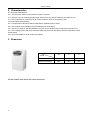
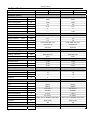
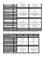
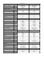
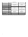
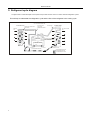
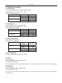
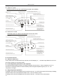
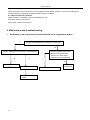
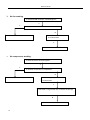
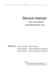
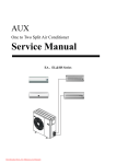
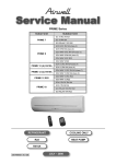
Content
GD Midea Refrigeration Equipment Co.,Ltd
SPLIT TYPE, HEAT PUMP AIR CONDITIONERS
WEBSITE:www.mideaaircom.com
Room Air Conditioner
Technical & service manual
Portable F SeriesMechanical type
[Models]
Electronic Control
MPF-09CEN2
MPF-09EEN2
MPF-12CEN2
MPF-12EEN2
Remote Control
1
MPF-09CRN2
MPF-09ERN2
MPF-12CRN2
MPF-12ERN2
Content
Content
1.
Precaution...........................................................................................................................................1
1.1
Safety Precaution.................................................................................................................................1
1.2
Warning ................................................................................................................................................1
1.3
Caution.................................................................................................................................................1
2.
Characteristics ...................................................................................................................................2
2.1 Structural characteristics ...............................................................................................................................2
2.2 Performance characteristics ..........................................................................................................................2
3.
Dimension...........................................................................................................................................2
All the models here have the same dimension....................................................................................................2
2
4.
Specification.......................................................................................................................................3
5.
Refrigerant cycle diagram.................................................................................................................7
6.
Operation limits..................................................................................................................................8
6.1
Cooling operation.................................................................................................................................8
6.2
Heating operation.................................................................................................................................8
7.
Schematic diagram and Wiring diagram .........................................................................................9
7.1.
Schematic diagram ..............................................................................................................................9
7.2.
Wiring diagram ...................................................................................................................................10
8.
Electronic function ..........................................................................................................................12
Service manual
1. Precaution
1.1 Safety Precaution
1.1.1 To prevent injury to the user or other people and property damage, the following instructions must be
followed.
1.1.2 Incorrect operation due to ignoring instruction will cause harm or damage.
1.1.3 Before service unit, be sure to read this service manual at first.
1.2 Warning
Installation
1.2.1 Do not use damaged power cords, plugs, or a loose socket.
1.2.2 Always use the power plug and socket with the ground terminal
1.2.3 Do not modify or extend the power cord
1.2.4 Do not turn the air-conditioner ON or OFF by plugging or unplugging the power plug
1.2.5 Use a dedicated outlet for this appliance
1.2.6 Grasp the plug to remove the cord from the outlet. Do not touch it with wet hands.
1.2.7 Do not place a heater or other appliance near the power cable
1.2.8 Do not allow water to run into electrical parts
1.2.9 Do not store or use flammable gas or combustibles near the air conditioner
1.2.10 Unplugging the unit if strange sounds, odors, or smoke comes from it
1.2.11 Be caution that water could not enter the product
1.3 Caution
Installation
1.3.1 Keep level even when installing the product
1.3.2 Use two or more people to lift and transport the air conditioner
Operation
1.3.3 Use a soft cloth to clean. Do not use harsh detergents, solvents, etc
1.3.4 Do not touch the metal parts of the product when removing the air filter. They are very sharp
1.3.5 Do not step on or put anything on the product
1.3.6 Do not insert hands or other objects through the air inlet or outlet while the air conditioner is plugged in
Service manual
2. Characteristics
2.1 Structural characteristics
2.1.1 There are four casters on the bottom for easy movement.
2.1.2 There is only one exhaust pipe(the length is from0.5 to 2m), which makes the A/C easier to use.
2.1.3 The condensate is received by large volume container, which is convenient to use.
2.2 Performance characteristics
2.2.1 Compressors of famous brands are adopted for reliability and low noise.
2.2.2 The products have multiple uses: dehumidifying and cloth drying.
2.2.3 There is no need for special installation; they can be moved around for simple and convenient use.
2.2.4 The heating system uses PTC electrical heater and will not be affected by ambient temperature, which
saves energy.
2.2.5 They are suitable for local cooling and heating.
3. Dimension
Dimension
W
H
D
Net Dimension
465
830
387
Packing Dimension
667
887
460
Mode
All the models here have the same dimension.
2
Service manual
4. Specification
Model
MPF-09CEN2
MPF-09CRN2
MPF-09EEN2
MPF-09ERN2
Control Method
Electric
Remote
Electric
Remote
Nameplate marking
Power supply
Ph-V-Hz
1φ,220-240V~,50Hz
1φ,220-240V~,50Hz
Btu/h
9000
9000
W
1090
1090
A
4.9
4.9
W/W
2.41
2.41
C
C
W
------
1700
g
R407C/500
R407C/500
Mpa
2.6
2.6
Moisture Removal
L/h
1.8
1.8
Water tank volume
L
inner water tank 3.5L
inner water tank 3.5L
Indoor air flow (Hi/Mi/Lo)
m3/h
340/270/210
340/270/210
Noise level (Hi/Mi/Lo)
dB(A)
53/51/49
53/51/49
Dimension (W*H*D)
mm
480×840×400
480×840×400
Packing (W*H*D)
mm
655×875×445
655×875×445
Net/Gross weight
Kg
37/41
37/41
Operation temp
℃
17-30
17-30
Ambient temp
℃
10-35
≤35
Application area
m2
12-20
12-20
Current
mA
90
90
Input
W
16
16
Water flow
ml/min
70
70
Height lift
m
4
4
Model
PG150X1C-4DZDE2
PG150X1C-4DZDE2
Type
Rotary
Rotary
Brand
GMCC
GMCC
1
Capacity
1
Power consumption
1
Rated current
EER
1
EEC
2
Electrical heater
System data
Refrigerant type
Design pressure
(Hi/Lo)
Dimension&Weight
Applicable ambient
Water Pump
Compressor
Capacity
W
2575/2610
2575/2610
Input
W
840/880
840/880
Rated current(RLA)
A
3.9/3.8
3.9/3.8
Locked rotor Amp(LRA)
A
21.7/23.7
21.7/23.7
B160-135-241E/MRA13430-9087
B160-135-241E/MRA13430-9087
Thermal protector
Capacitor
uF
25uF/ 370V
25uF/ 370V
Refrigerant oil
cc
400
400
YDK80-4M
YDK80-4M
Fan Motor
Model
3
Service manual
Input
W
181/151/107/93
181/151/107/93
Capacitor
uF
6uF/450V
6uF/450V
r/min
1230/1110/880/800
1230/1110/880/800
2
2
21X13.37
21X13.37
1.4
1.4
Hydrophilic aluminium
Hydrophilic aluminium
Speed(hi/mi/lo)
Evap.
a.Number of rows
b.Tube pitch(a)x row
pitch(b)
c.Fin spacing
mm
mm
d.Fin type (code)
e.Tube outside dia.and type
mm
Ф7×0.25×0.18, innergroove tube
Ф7×0.25×0.18, innergroove tube
f.Coil length x height x width
mm
335x294x26.74
335x294x26.74
2
2
2
2
21X13.37
21X13.37
1.4
1.4
Unhydrophilic aluminium
Unhydrophilic aluminium
Ф7×0.25×0.18, innergroove tube
Ф7×0.25×0.18, innergroove tube
542x294x13.37
542x294x13.37
519x294x13.37
519x294x13.37
2
2
86/176/269
86/176/269
g.Number of circuits
Cond.
a.Number of rows
b.Tube pitch(a)x row
pitch(b)
c.Fin spacing
mm
mm
d.Fin type (code)
e.Tube outside dia.and type
mm
f.Coil length x height x width
mm
g.Number of circuits
Stuffing Quantity
20'/40'40'HQ
set
1 The test condition is according to EN14511 standard at application rating conditions.
2 EEC (Energy efficiency class). The test condition is according to EN14511 standard at standard condition.
Model
MPF-12CEN2
MPF-12CRN2
MPF-12EEN2
MPF-12ERN2
Control Method
Electric
Remote
Electric
Remote
Nameplate marking
Power supply
Ph-V-Hz
1φ,220-240V~,50Hz
1φ,220-240V~,50Hz
Btu/h
11500
11500
W
1380
1380
A
5.4
5.4
W/W
2.42
2.42
C
C
W
------
1700
g
R407C/560
R407C/560
Mpa
2.6
2.6
Moisture Removal
L/h
2
2
Water tank volume
L
inner water tank 3.5L
inner water tank 3.5L
Indoor air flow (Hi/Mi/Lo)
m3/h
340/270/210
340/270/210
Noise level (Hi/Mi/Lo)
dB(A)
53/51/49
53/51/49
1
Capacity
1
Power consumption
1
Rated current
EER
1
EEC
2
Electrical heater
System data
Refrigerant type
Design pressure
4
(Hi/Lo)
Service manual
Dimension&Weight
Dimension (W*H*D)
mm
480×840×400
480×840×400
Packing (W*H*D)
mm
655×875×445
655×875×445
Net/Gross weight
Kg
34/44
34/44
Operation temp
℃
17-30
17-30
Ambient temp
℃
10-35
≤35
Application area
m2
15-22
15-22
Current
mA
90
90
Input
W
16
16
Water flow
ml/min
70
70
Height lift
m
4
4
Model
PG180X1C-4DZDE3
PG180X1C-4DZDE3
Type
Rotary
Rotary
Brand
GMCC
GMCC
Applicable ambient
Water Pump
Compressor
Capacity
W
3120/3150
3120/3150
Input
W
995/1030
995/1030
Rated current(RLA)
A
4.6/4.4
4.6/4.4
Locked rotor Amp(LRA)
A
19.8
19.8
B160-135-141E
B160-135-141E
Thermal protector
Capacitor
uF
30uF/ 370V
30uF/ 370V
Refrigerant oil
cc
400
400
Model
CG633PB1-C
CG633PB1-C
Type
Rotary
Rotary
Brand
Hitachi
Hitachi
Compressor(alternative)
Capacity
W
2850
2850
Input
W
970
970
Rated current(RLA)
A
4.6
4.6
Locked rotor Amp(LRA)
A
17.4
17.4
Capacitor
uF
35uF/ 400V
35uF/ 400V
Refrigerant oil
cc
400
400
YDK80-4M
YDK80-4M
Thermal protector
Fan Motor
Model
Input
W
181/151/107/93
181/151/107/93
Capacitor
uF
6uF/450V
6uF/450V
r/min
1230/1110/880/800
1230/1110/880/800
2
2
Speed(hi/mi/lo)
Evap.
a.Number of rows
b.Tube pitch(a)x row pitch(b)
mm
21X13.37
21X13.37
c.Fin spacing
mm
1.4
1.4
5
Service manual
d.Fin type (code)
Hydrophilic aluminium
e.Tube outside dia.and type
mm
f.Coil length x height x width
mm
g.Number of circuits
Hydrophilic aluminium
Ф7×0.25×0.18, innergroove
Ф7×0.25×0.18, innergroove tube
tube
380x294x26.74
380x294x26.74
2
2
2
2
Cond.
a.Number of rows
b.Tube pitch(a)x row pitch(b)
mm
21X13.37
21X13.37
c.Fin spacing
mm
1.4
1.4
Unhydrophilic aluminium
Unhydrophilic aluminium
d.Fin type (code)
e.Tube outside dia.and type
mm
f.Coil length x height x width
mm
g.Number of circuits
Ф7×0.25×0.18, innergroove
Ф7×0.25×0.18, innergroove tube
tube
704x294x13.37
704x294x13.37
660x294x13.37
660x294x13.37
2
2
86/176/269
86/176/269
Stuffing Quantity
20'/40'40'HQ
set
1 The test condition is according to EN14511 standard at application rating conditions.
2 EEC (Energy efficiency class). The test condition is according to EN14511 standard at standard condition.
6
Service manual
5. Refrigerant cycle diagram
The figure below is a brief description of the important components and their function in what is called the refrigeration system.
This will help to understand the refrigeration cycle and the flow of the refrigerant in the cooling cycle.
ROOM AIR CONDITIONER
CYCLE OF RE FRIGERATION
EVAPORATOR
SUCTION LINE
COOL LOW
PRESSURE VAPOR
COMPLETE LIQUID BOIL
OFF POINT
COOLED
AIR
VAPOR INLET
CONDENSER
HOT DISCHARGE
AIR
ROOM AIR HEAT LOAD
MOTOR
OUTSIDE COOLING
AIR FOR REFRIGERANT
PASS THROUGH
COMPRESSOR
LIQUID
PRESSURE
DROP
OIL
LIQUID OUTLET
(LIQUID REFRIGERANT)
CAPILLARY
HIGH PRESSURE VAPOR
LIQUID REFRIGERANT
LOW PRESSURE VAPOR
7
Service manual
6. Operation limits
6.1 Cooling operation
Outdoor unit air temp.℃ DB
Indoor air temp. ℃ DB
Note: The chart is the result from the continuous operation under constant air temperature conditions. However,
excludes the initial pull-down stage.
6.2 Heating operation
Indoor air temp. ℃ DB
Outdoor unit air temp.℃ DB
Note: The chart is the result from the continuous operation under constant air temperature conditions. However,
excludes the initial pull-down stage.
8
D18
CN3
R8
8.1K/1%
T1_room
1
2
R5
1K
C8
104
Current
R9
8.1K/1%
T2_I.pipe
1
R4 12K
IN4148
D8
D7
IN4148
IN4148
D6
D5
IN4148
E6
10uF/16V
R12 2K
+5V
+5V
BUZ1
BUZZER1
E10
1.4K/1%
R14
D9
1N4148
R13
16K
+5V
10uF/16V
E5
R11 2K
10uF/16V
E4
2K
C25
104
RST
2200uF/25V
R10
3
E1
2200uF/25V
IN4007*4
IC5 KIA7042
2
1
+12V
+5V
2
D19
D17
D
D16
D4
D3
C
B
等离子集尘器电源
CN2
BUZ '
C5
104
TRANS
4
3
2
1
D2
D1 IN4007*4
7812
T2_I.pipe
+5V
0057h
E2
3
R2
8.06K
R1
10K
+5V
SEG4
BUZ
9
19
18
17
16
15
14
13
12
11
10
1.2uF/450V
T2
+12V-a
8
7
6
5
4
3
2
?
P22
P21
VDD1
P20
P33
P32
P31
P30
P11
P10
AVSS
AN5
AN4
P04
VSS1
P05
P50
P51
P52
P53
AVDD
AVREF
AN0
AN1
AN2
AN3
OUT3
OUT4
OUT5
OUT6
OUT7
VDD
IN3
IN4
IN5
IN6
IN7
VSS
IC6 PC817
BT131
TR1
T1
333
C15
L2
OUT2
IN2
UJN2003
OUT1
IN1
Z1
12V
1K
22
23
24
R28
11K/2W
7
JR3
JR2
JR5
JR4
IN4007
D15
1
ZR1
N
10D471K
L1
Q0
Q1
Q2
Q3
Q4
Q5
Q6
Q7
N
1
CN11
+5V
VALVE
74HC164
Dsa
Dsb
CP
MR
Vcc
GND
IC8
10K
10K
10K
2K
JR7 10K
JR6 10K
C16
102
2
8
9
C24 14
104
+5V
C17
102
SEG4
SEG3
FRESH
REC
ZERO
FANSP_FEEDBACK
FAN_OUT
COM3
+5V
COM2
R29
11K/2W
SWING
CN12
E9
470uF/25V
5
4
3
2
1
25 FRESH
26 VALVE
27 REC
28 ZERO
29 FANSP
4M
X1
COM1
SDA
SCL
RST
R7
1M
30 FAN_OUT
31 COM3
32
33 COM2
34 COM1
35 SDA
36 SCL
37
38
39
40 RST
41 X2
42 X1
+12V-a
FAN_IN '
COMP '
BUZ '
+12V-a
R26
9
10
11
12
13
14
FAN_IN '
P23
P03
15
P24
P02
IC7
XT2
VppIC
P01
XT1
P26
P00
RESET
X2
VDD0
P25
X1
16
IC4 UPD789166
A
DIS1
WT4021BG
R55 330
R54 330
R49 330
R48 330
R47 330
R46 330
R45 330
R44 330
t
PTC
82RM
0.1uF/275VAC
C23
3
4
5
6
10
11
12
13
8
7
6
5
JR1 2K
R61 2K
COM2
R15R17
12K12K
VCC
WC
SCL
SDA
C2
C9
104
102
C10
R20
Q2
9014
Q8
9012
TRANS_IN
2
1
CN15
Q9
9012
LED9
运行灯
LED7
化霜
LED8
定时
LED6
自动
LED5
氧吧
Q10
9012
10uF/16V
RECEIVER_V
REC1
2K
D22
IN4148
VALVE
FAN_OUT
2K
R35
2K
R34
COMP '
RY4
RELAY-SPST
L1
RY3
RELAY-SPST
LOAD_HEAT L
1
2
L1
3.15A/250V
FUSE1
R36
51/1W
C20
333
RY5
RELAY-SPST
LOAD_VALVE
GNDB
O2_L
1
CN10
9014
Q12
2
1
CN16
FAN_BACK
3
2
1
L(POWER_IN PORT)
RY6
COMP
+12V-a LOAD_COMP
Q7
9014
IN4148
D24
+12V-a
5.1K
+12V-b
SW2
C12
103
R215.1K
D13
IN4148 +12VCN4
R63
+12V-b
+5V
LOAD_FAN OUT
CN13
Q6
9014
IN4148
D23
+12V-a
Q5
9014
+12V-a
+12V-a PC817
R33
9014
Q11
1K
FANSP_FEEDBACK
IC9
外风机、四通阀控制
单冷机无此部分
O2
氧吧控制
R61
2K
R62
等离子集尘器控制
104
E7
REC
V
C11 GND
1K
R19 150
ZERO
1
2
3
4
104
SW1
COM3
R18 10K
A0
A1
A2
GND
IC2 24C04
+5V
R16 12K
R39
10K
REC
+5V
R41+5V
R42+5V
R43
2K
2K
2K
R56 10K
R57 10K
R58 10K
+5V
COM1
D11 1N4148
D12 1N4148
B
SDA
SCL
R38
10K
+5V
1.JR1=2K 不带掉电记忆;不接JR1,带掉电记忆。
2.去掉预留的换气功能,控制口的输出功能去掉,保留输入功能,用做自检检测口。
JR2:端口高电平,芯片自检;JR3:端口低电平,芯片正常。
3.清新控制口兼作芯片快检选择口。
JR4:端口高电平,芯片快检;JR5:端口低电平,芯片正常并可控输出。
4.JR6:端口高电平,选择单冷机型;JR7:端口低电平,选择冷暖机型 。
说明:
VSS0
104
C4
+5V
R25 51/1W
C19
104
COMP
BUZ
FAN_IN
STEP_I4
STEP_I3
STEP_I2
1
21
CURRENT20
T2
T1
SEG4
SEG3
O2
COMP
8
6
STEP_I2
7
5
STEP_I1
STEP_I4
4
BUZ
STEP_I3
3
2
1
FAN_IN
STEP_I1
2K R24
E3
470uF/16V
3
TC_SELECT
Current
T2_I.pipe
T1_room
+5V
O2
COMP
STEP_I4
STEP_I3
STEP_I2
STEP_I1
TC_SELECT
C14
Vout
FAN_IN
C26
104
TC_SELECT
FAN_IN
5
4
3
2
1
7805
+5V
Vin
IC3
R59 R60
10K 10K
CN6
R3
5.1K
R62
10K
SEG3
104
C24
GNDB
E11
+12V-b
104
C3
+12V-a
1
1000uF/16V
3
1000uF/16V
+5V
Vout
Vout
CT1
COM
3
2
1
CN5
T1_room
Vin
IC10 7812
Vin
IC1
D10
1N4148
R6
1K/1%
104
C7
104
C6
104
C23
1
104
C1
1
GND
2
GND
2
GND
2
A
G
com1
com2
h
g
f
e
d
c
b
a
9
FRESH
CN1
Service manual
7. Schematic diagram and Wiring diagram
7.1. Schematic diagram
Service manual
7.2. Wiring diagram
MPF-09CEN2, MPF-09CRN2, MPF-10CEN2, MPF-10CRN2
MPF-09CEN2, MPF-09CRN2, MPF-14CEN2, MPF-14CRN2
MPF-09EEN2, MPF-09ERN2, MPF-10EEN2, MPF-10ERN2
MPF-12EEN2, MPF-12ERN2, MPF-14EEN2, MPF-142ERN2
10
Service manual
MPF-09CE, MPF-09CR, MPF-10CE, MPF-12CR, MPF-12CE, MPF-12CR
MPF-09EE, MPF-09ER, MPF-10EE, MPF-10ER, MPF-12EE, MPF-12ER
11
Service manual
8. Electronic function
8.1 Cooling mode
The air flow speed can be set at high, medium and low.
The temperature can be set from 17℃~-30℃.
The action of the compressor
Condition
Temp. up
Temp. down
Compressor
T> Ts+1
On
T<Ts+1
Off
T> Ts
On
T<Ts
Off
.
8.2 Heating mode
The air flow speed can be set at high or low;
The temperature can be set from 17℃~-30℃.
The action of the PTC heater:
Condition
Temp. up
Temp. down
T> Ts+1
PTC heater
Off
T<Ts+1
On
T> Ts
Off
T<Ts
On
8.3 Dehumidifying mode
The fan works at High speed.
The action of the compressor
Condition
Temp. up
Temp. down
Ta: room temp.
Ta> 15℃
Compressor
On
T<15℃
Off
Ta> 13℃
On
T<13℃
Off
8.4 Air blowing mode
The fan can run at high, medium or low speed.
8.5 Timer
8.5.1 Timer On
Push the Timer On button to start the timer;
Time is relative time, from
0.5-1.0-1.5-2.0-2.5-3.0-3.5-4.0-4.5-5.0-5.5-6.0-6.5-7.0-7.5-8.0-8.5-9.0-9.5-10-11-12-13-14-15-16-17-18-19-20-2
1-22-23-24-0.0;
8.5.2 Timer Off
Push the Timer On button to start the timer;
Time is relative time, from
0.5-1.0-1.5-2.0-2.5-3.0-3.5-4.0-4.5-5.0-5.5-6.0-6.5-7.0-7.5-8.0-8.5-9.0-9.5-10-11-12-13-14-15-16-17-18-19-20-2
1-22-23-24-0.0;
.
12
Service manual
8.6 Operation panel
8.6.1 With PTC model
OPERATION PANEL OFTHE AIR CONDITIONER(COOLING AND HEATING)
DI GITA L DISPLA Y
FAN SPEE D IN DIC ATOR
COOL/ DRY /FAN /HEA T IN DIC ATOR
Gr een lamp wi ll l ight w hen the mode is s e lect ed
WATER FU LL IN DICAT OR
Red lamp wil l bli nk when the tank i s ful l
TE MP SET T ING BUT TON
Pr ess y our des ir ed ro om te mpe ratu re
se tting by pr es si ng th e but ton " " ( up)
or butto n " "( dow n)
P OWE R IN DICAT OR
IN FRA RED
SIGNA L R ECEIV ER
POWE R BU TTON
Tu rn on/off the u nit
MODES BUT TON
Se lect the operation mode
fro m COOL.DRY.FAN.HEAT
TI MER ON/OFF IND ICATOR
FAN SPEED BUTTON
Select the fan s peed from
HIGH.M ED or L OW
TI MER ON/OFF BU T TON
Pr ogra m the on/o ff timer func ti on
8.6.2 Without PTC model
OPERATION PANEL OF THE AIR CONDITIONER(COOLING ONLYTYPE)
DI GITA L DISPLA Y
FAN SPEE D IN DIC ATOR
COOL/ DRY /FAN IND ICAT OR
Gr een lamp wi ll l ight w hen the mode is s e lect ed
WATER FU LL IN DICAT OR
Red lamp wil l bli nk when the tank i s ful l
TE MP SET T ING BUT TON
Se lect your desir ed ro om temp eratu re
se tting by pr es si ng th e but ton " " ( up)
or butto n " "( dow n)
IN FRA RED
SIGNA L R ECEIV ER
TI MER ON/OFF IND ICATOR
TI MER ON/OFF BUTT ON
Pr ogra m the on/o ff timer func ti on
P OWE R IN DICAT OR
POWE R BU TTON
Tu rn on/off the u nit
MODES BUT TON
Se lect the operation mode
fro m COOL.DRY.FAN.
FAN SPE ED B UTT ON
Pres s the butt on to sele ct
the fan s p eed from
HIGH.M ED or LOW
8.7 Protective function
8.7.1 Alarm on water level
At any mode, when the water level is up to the limit, the LED display ‘P1’, the alarm lamp flashes at 2 Hz, and
the machine enters into air blowing mode.
8.7.2 Low temperature protection for the evaporator
At cooling and dehumidifying modes, if the pipe temperature is lower than 2℃ after compressor runs for 3
minutes, the compressor will be shut down instantly. When the pipe temperature goes up to 10℃, the
compressor runs again.
8.7.3 High temperature protection
At heating mode, when the temperature at air outlet is more 75℃, the PTC will be turned off; the lamp of heating
will flash at 2Hz, when the temperature lowers to 55℃, the PTC returns to work.
At heating mode, when the temperature at air outlet is more 90℃, the fuse of PTC will be broken.
13
Service manual
8.7.4 The delayed protection for compressor
When the power is on for the first time, the compressor starts without waiting for 3 minutes; re-starting the
machine after the compressor is stopped needs to wait for 3 minutes.
8.7.5 Sensor defective protection
When the sensor is defective, the unit will display the error.
Pipe temp. sensor error code: E1
Room temp. sensor error code: E2
9. Malfunction and troubleshooting
a. No display or no response to remote controller or no response to button ..
Y
Is there DC5V between pin 3 and pin 7 of main chip
N
Check if AC230V exists at the
Is CN5 , CN6 and CN7 connector connected good?
primary coil of transformer.
Check if 14V exists at the
Y
N
Y
secondary coil of transformer.
N
Connection
l
d
Transformer
Display board failed.
Replace the display
board
14
Control board is defective.
is defective.
Service manual
b. No fan running.
Is CN5 and CN6 connector connected good?
Y
Y
Is AC230V on fan motor?
N
Check fan motor and capacitor
Is the RY1,RY2,RY3 normal
in Control board
Y
Control board is defective
c. No compressor working.
Is CN5 connector connected good?
Y
Y
Is AC230V on R and S in compressor?
N
Check compressor and capacitor
Is the Relay (RY5) normal in
Control board
Y
Check the 17 leg of main chip ,is the 5V on this leg?
N
Control board is defective
15
Service manual
d. No water pump running.
Is CN5 and CN7 connector connected good?
Y
Y
Is AC230V on water pump?
N
Check fan motor and capacitor
Is the RY4 normal in Control board
Y
Control board is defective
e. No PTC working( only for with PTC heater model).
Set temperature at 32℃ and make sure the room temperature is below 30℃.
Is AC230V available on PTC
N
Y
The connection between PTC and Control
Is Protector normal?
board is right in relay
Y
Control board or display
N
board is defective
Connect the connection again.
16
PTC is defective