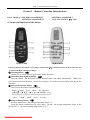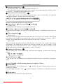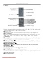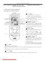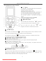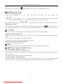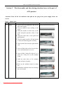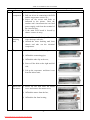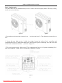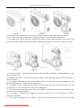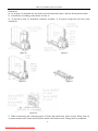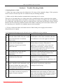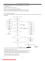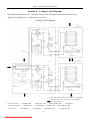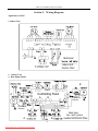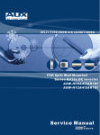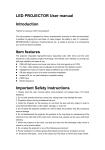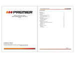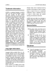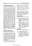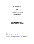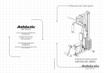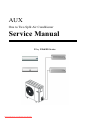
1
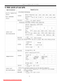
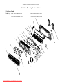
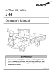
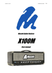
AUX
One to Two Split Air Conditioner
Service Manual
EA、EL&HS Series
Downloaded from AC-Manual.com Manuals
CONTENTS
Section 1 Important Notice………………………………………………………………..………1
Section 2 Technical Specifications…………………………………………………………..……2
Section 3 remote controller introductions…………………………………………………..……. 9
Section 4 Electronic Controller introductions…………………………………………….……....23
Section 5 The disassembly and the relating attention issues to the part of AUX product……......32
Part 1. Indoor unit……………………………………………………………………………..…....32
Part 2. Outdoor unit……………………………………………….………………….………..........34
Section 6 Trouble shooting Guide……………………………………………………….…….….37
Section 7 Explosion View…………………………………………………………………….…..47
Part 1. Indoor Unit……………………….…………………………………………………….……47
Part 2. Outdoor Unit………………………………………………………………..…………….….51
Section 8 Cooling Cycle Diagram……………………………………………………………..….54
Section 9 Wiring Diagram…………………………………………………………………..…….55
Section 10 Service Record……………………………………………………………………..….57
.
Downloaded from AC-Manual.com Manuals
AUX Air Conditioner Service manual
Section 1
Important Notice
This service manual is intended for use by individuals possessing adequate backgrounds
of electrical. Electronic and mechanical experience. Any attempt to repair the appliance
may result in personal injury and property damage. The manufacturer or seller cannot
be responsible for the interpretation of this information. Nor can it assume any liability
in connection with its use.
The information. Specifications and parameter are subject to change due to technical
modification or improvement without any prior notice. The accurate specifications are
presented on the nameplate label.
How to order spare parts
To have your order filled promptly and correctly. Please furnish the following
information:
1. Model No. with Indoor or outdoor
2. No. in the Explosion View
3. Part Name
4. The quantity you ordered
1
Downloaded from AC-Manual.com Manuals
AUX Air Conditioner Service manual
Section 2
Technical Specifications
ASW-H09A+09A4/HS2R-IV
Model No
Indoor Unit A
(System A)
Items
Performance
Type
Wall mounted model
2.5
2.5
/
Dehumidify
kg/h
1.0
1.0
/
Heating
kw
2.75
2.75
/
Noise level
dB(A)
40
40
62
2.3
2.3
/
2.4
2.4
/
1060
1050
2030
1070
1060
2000
4.60
4.56
8.83
4.65
4.60
8.7
Cooling
EER
Heating
Electrical Data
Refrigerating System
W/W
φ-V-Hz
Cooling
Rated input
Heating
Cooling
Rated current
Heating
W
A
1 / 220-240V~/ 50Hz
Length
m
2
2
4.8
Class
/
250V 10A
250V 10A
400V 25A
Starting Current
A
21.7
21.7
/
Fuse capacity
A
3.15
3.15
3.15
Refrigerant/Charge
g
R407c/700
R407c/730
/
Type
/
Rotary
Rotary
/
Model
/
PG165X1C-4DFDE2
PG165X1C-4DFDE2
/
Rated input
W
955/980
955/980
/
Overload
Protector
/
MRA13430-9087
B160-135-241E
MRA13430-9087
B160-135-241E
/
Row*Hole
2*10
2*10
1*31
Type
Capillary tube
Specification(mm)
φ2.6*400+φ2.6*450
φ2.6*350+φ2.6*400
/
m3/h
420
420
/
Cooling
r/min
1080/950/900/800
1080/950/900/800
860
Heating
r/min
1080/950/900/850
1080/950/900/850
860
Fan type
/
Cross flow
Cross flow
Propeller fan
Fan motor output
W
19
19
68
Connecting
Pipe
OD(mm)*L(mm)
Supply cord
Compressor
Heat exchanger
Air Volume
Fan System
Heating pump
kw
Expansion device
Connection
Outdoor Unit
Cooling
Power supply
Others
Indoor Unit B
(System B)
Fan Speed
H/M/L/Q
Gas /Liquid
Φ9.52×5000/Φ6.35×5000
Drainage Pipe
OD(mm)*L(mm)
Φ14×780
Suitable area
m2
12-17
12-17
/
Net dimensions
(W x H x D)
mm
80.2*26.2*16.5
80.2*26.2*16.5
331*846*901
Net weight
kg
9.5
9.5
65
2
Downloaded from AC-Manual.com Manuals
AUX Air Conditioner Service manual
ASW-H09A+12A4/HS2R-V
Model No
Indoor Unit A
(System A)
Items
Performance
Type
Wall mounted model
3.2
2.5
/
Dehumidify
kg/h
1.2
1.0
/
Heating
kw
3.6
2.75
/
Noise level
dB(A)
43
40
62
2.3
2.3
/
2.4
2.4
/
1320
970
2150
1360
1070
2300
5.74
4.22
9.35
5.91
4.65
10
Cooling
EER
Heating
Electrical Data
Refrigerating System
W/W
φ-V-Hz
Cooling
Rated input
Heating
Cooling
Rated current
Heating
W
A
1 / 220-240V~/ 50Hz
Length
m
2
2
4.8
Class
/
250V 10A
250V 10A
400V 25A
Starting Current
A
30.5
21.7
/
Fuse capacity
A
3.15
3.15
3.15
Refrigerant/Charge
g
R407c/1100
R407c/980
/
Type
/
Rotary
Rotary
/
Model
/
4KS225EBB
4PS164EAC
/
Rated input
W
1300/1325
920/945
/
Overload
Protector
/
Inner
B165-150-241H
/
Row*Hole
2*12
2*10
2*31
Type
Capillary tube
Specification(mm)
φ3.0*500+φ3.0*500
φ2.6*350+φ2.6*300
/
m3/h
620
420
/
Cooling
r/min
1180/1050/950/800
1080/950/900/800
860
Heating
r/min
1180/1050/950/850
1080/950/900/850
860
Fan type
/
Cross flow
Cross flow
Propeller fan
Fan motor output
W
19
19
68
Connecting
Pipe
OD(mm)*L(mm)
Supply cord
Compressor
Heat exchanger
Air Volume
Fan System
Heating pump
kw
Expansion device
Connection
Outdoor Unit
Cooling
Power supply
Others
Indoor Unit B
(System B)
Fan Speed
H/M/L/Q
Gas /Liquid
Φ9.52×5000/Φ6.35×5000
Drainage Pipe
OD(mm)*L(mm)
Φ14×780
Suitable area
m2
12-21
12-17
/
Net dimensions
(W x H x D)
mm
89.2*29.6*17.6
80.2*26.2*16.5
331*846*901
Net weight
kg
10.5
9.5
70
3
Downloaded from AC-Manual.com Manuals
AUX Air Conditioner Service manual
ASW-H12A+12A4/HS2R-VI
Model No
Indoor Unit A
(System A)
Items
Performance
Type
Wall mounted model
3.2
3.2
/
Dehumidify
kg/h
1.2
1.2
/
Heating
kw
3.6
3.6
/
Noise level
dB(A)
43
43
62
2.3
2.3
/
2.4
2.4
/
1270
1270
2530
1360
1360
2500
5.52
5.52
11
5.91
5.91
10.87
Cooling
EER
Heating
Electrical Data
Refrigerating System
W/W
φ-V-Hz
Cooling
Rated input
Heating
Cooling
Rated current
Heating
W
A
1 / 220-240V~/ 50Hz
Length
m
2
2
4.8
Class
/
250V 10A
250V 10A
400V 25A
Starting Current
A
30.5
30.5
/
Fuse capacity
A
3.15
3.15
3.15
Refrigerant/Charge
g
R407c/1100
R407c/1100
/
Type
/
Rotary
Rotary
/
Model
/
4KS225EBB
4KS225EBB
/
Rated input
W
1300/1325
1300/1325
/
Overload
Protector
/
Inner
Inner
/
Row*Hole
2*12
2*12
2*31
Type
Capillary tube
Specification(mm)
φ3.0*500+φ3.0*500
φ3.0*500+φ3.0*500
/
m3/h
620
620
/
Cooling
r/min
1180/1050/950/800
1180/1050/950/800
860
Heating
r/min
1180/1050/950/850
1180/1050/950/850
860
Fan type
/
Cross flow
Cross flow
Propeller fan
Fan motor output
W
19
19
68
Connecting
Pipe
OD(mm)*L(mm)
Supply cord
Compressor
Heat exchanger
Air Volume
Fan System
Heating pump
kw
Expansion device
Connection
Outdoor Unit
Cooling
Power supply
Others
Indoor Unit B
(System B)
Fan Speed
H/M/L/Q
Gas /Liquid
Φ9.52×5000/Φ6.35×5000
Drainage Pipe
OD(mm)*L(mm)
Φ14×780
Suitable area
m2
12-21
12-21
/
Net dimensions
(W x H x D)
mm
89.2*29.6*17.6
89.2*29.6*17.6
331*846*901
Net weight
kg
10.5
10.5
75
4
Downloaded from AC-Manual.com Manuals
AUX Air Conditioner Service manual
ASW-H09A+09A4/EA(L)2R1-I
Model No
Indoor Unit A
(System A)
Items
Performance
Type
Wall mounted model
2.5
2.5
/
Dehumidify
kg/h
1.0
1.0
/
Heating
kw
2.75
2.75
/
Noise level
dB(A)
38
38
62
2.6
2.6
/
2.6
2.6
/
960
960
1820
950
950
1780
4.17
4.17
7.91
4.13
4.13
7.74
Cooling
EER
Heating
Electrical Data
Refrigerating System
W/W
φ-V-Hz
Cooling
Rated input
Heating
Cooling
Rated current
Heating
W
A
1 / 220-240V~/ 50Hz
Length
m
2
2
4.8
Class
/
250V 10A
250V 10A
400V 25A
Starting Current
A
21.7
21.7
/
Fuse capacity
A
3.15
3.15
3.15
Refrigerant/Charge
g
R410a/750
R410a/800
/
Type
/
Rotary
Rotary
/
Model
/
PA108X1C-4FZDE
PA108X1C-4FZDE
/
Rated input
W
885/915
885/915
/
Overload
Protector
/
B160-135-241E
MRA13430-9087
B160-135-241E
MRA13430-9087
/
Row*Hole
2*11
2*11
1*31
Type
Capillary tube
Specification(mm)
φ2.6*500+φ2.6*800
φ2.6*700+φ2.6*700
/
m3/h
420
420
/
Cooling
r/min
980/900/850/800
980/900/850/800
860
Heating
r/min
980/900/850/850
980/900/850/850
860
Fan type
/
Cross flow
Cross flow
Propeller fan
Fan motor output
W
13
13
68
Connecting
Pipe
OD(mm)*L(mm)
Φ9.52×5000/Φ6.35×5000
Drainage Pipe
OD(mm)*L(mm)
Φ14×780
Suitable area
m2
12-17
12-17
/
Net dimensions
(W x H x D)
mm
745*250*210
745*250*210
331*846*901
Net weight
kg
9.5
9.5
65
Supply cord
Compressor
Heat exchanger
Air Volume
Fan System
Heating pump
kw
Expansion device
Connection
Outdoor Unit
Cooling
Power supply
Others
Indoor Unit B
(System B)
Fan Speed
H/M/L/Q
Gas /Liquid
5
Downloaded from AC-Manual.com Manuals
AUX Air Conditioner Service manual
ASW-H09A+12A4/EA(L)2R1-II
Model No
Indoor Unit A
(System A)
Items
Performance
Type
Wall mounted model
3.2
2.5
/
Dehumidify
kg/h
1.2
1.0
/
Heating
kw
3.55
2.75
/
Noise level
dB(A)
41
38
62
2.6
2.6
/
2.6
2.6
/
1150
900
2010
1220
980
2050
5.0
3.91
8.74
5.3
4.26
8.91
Cooling
EER
Heating
Electrical Data
Refrigerating System
W/W
φ-V-Hz
Cooling
Rated input
Heating
Cooling
Rated current
Heating
W
A
1 / 220-240V~/ 50Hz
Length
m
2
2
4.8
Class
/
250V 10A
250V 10A
400V 25A
Starting Current
A
30.5
21.7
/
Fuse capacity
A
3.15
3.15
3.15
Refrigerant/Charge
g
R410a/1100
R410a /950
/
Type
/
Rotary
Rotary
/
Model
/
PA140X2C-4FT
PA108X1C-4FZDE
/
Rated input
W
1160/1200
885/915
/
Overload
Protector
/
Inner
B160-135-241E
MRA13430-9087
/
Row*Hole
2*13
2*11
2*31
Type
Capillary tube
Specification(mm)
φ3.0*900+φ3.0*1000
φ2.6*500+φ2.6*800
/
m3/h
550
550
/
Cooling
r/min
1180/1050/900/800
980/900/850/800
860
Heating
r/min
1180/1050/900/850
980/900/850/850
860
Fan type
/
Cross flow
Cross flow
Propeller fan
Fan motor output
W
19
13
68
Connecting
Pipe
OD(mm)*L(mm)
Φ9.52×5000/Φ6.35×5000
Drainage Pipe
OD(mm)*L(mm)
Φ14×780
Suitable area
m2
12-21
12-17
/
Net dimensions
(W x H x D)
mm
745*250*210
745*250*210
331*846*901
Net weight
kg
10.5
9.5
70
Supply cord
Compressor
Heat exchanger
Air Volume
Fan System
Heating pump
kw
Expansion device
Connection
Outdoor Unit
Cooling
Power supply
Others
Indoor Unit B
(System B)
Fan Speed
H/M/L/Q
Gas /Liquid
6
Downloaded from AC-Manual.com Manuals
AUX Air Conditioner Service manual
ASW-H12A+12A4/EA(L)2R1-III
Model No
Indoor Unit A
(System A)
Items
Performance
Type
Wall mounted model
3.2
3.2
/
Dehumidify
kg/h
1.2
1.2
/
Heating
kw
3.55
3.55
/
Noise level
dB(A)
41
41
62
2.6
2.6
/
2.6
2.6
/
1130
1130
2230
1180
1180
2200
4.91
4.91
9.7
5.13
5.13
9.57
Cooling
EER
Heating
Electrical Data
Refrigerating System
W/W
φ-V-Hz
Cooling
Rated input
Heating
Cooling
Rated current
Heating
W
A
1 / 220-240V~/ 50Hz
Length
m
2
2
4.8
Class
/
250V 10A
250V 10A
400V 25A
Starting Current
A
30.5
30.5
/
Fuse capacity
A
3.15
3.15
3.15
Refrigerant/Charge
g
R410a/1150
R410a/1150
/
Type
/
Rotary
Rotary
/
Model
/
ASL135SV-C7LU
ASL135SV-C7LU
/
Rated input
W
1120
1120
/
Overload
Protector
/
Inner
Inner
/
Row*Hole
2*13
2*13
2*31
Type
Capillary tube
Specification(mm)
φ3.0*900+φ3.0*1000
φ3.0*900+φ3.0*1000
/
m3/h
550
550
/
Cooling
r/min
1180/1050/900/800
1180/1050/900/800
860
Heating
r/min
1180/1050/900/850
1180/1050/900/850
860
Fan type
/
Cross flow
Cross flow
Propeller fan
Fan motor output
W
19
19
68
Connecting
Pipe
OD(mm)*L(mm)
Supply cord
Compressor
Heat exchanger
Air Volume
Fan System
Heating pump
kw
Expansion device
Connection
Outdoor Unit
Cooling
Power supply
Others
Indoor Unit B
(System B)
Fan Speed
H/M/L/Q
Gas /Liquid
Φ9.52×5000/Φ6.35×5000
Drainage Pipe
OD(mm)*L(mm)
Φ14×780
Suitable area
m2
12-21
12-21
/
Net dimensions
(W x H x D)
mm
745*250*210
745*250*210
331*846*901
Net weight
kg
10.5
10.5
75
7
Downloaded from AC-Manual.com Manuals
AUX Air Conditioner Service manual
ASW-12A+12A2/EA(L)2-III
Model No
Indoor Unit A
(System A)
Items
Performance
Type
Wall mounted model
3.2
3.2
/
Dehumidify
kg/h
1.1
1.1
/
Heating
kw
/
/
/
Noise level
dB(A)
41
41
62
2.56
2.56
/
2.56
2.56
/
1250
1250
2500
/
/
/
5.7
5.7
11.4
/
/
/
Cooling
EER
Heating
Electrical Data
Refrigerating System
W/W
φ-V-Hz
Cooling
Rated input
Heating
Cooling
Rated current
Heating
W
A
1 / 208-230V~/ 60Hz
Length
m
2
2
4.8
Class
/
250V 10A
250V 10A
400V 25A
Starting Current
A
30.5
30.5
/
Fuse capacity
A
3.15
3.15
3.15
Refrigerant/Charge
g
R22/1280
R22/1280
/
Type
/
Rotary
Rotary
/
Model
/
2P20S236A1G
2P20S236A1G
/
Rated input
W
1235
1235
/
Overload
Protector
/
Outer
Outer
/
Row*Hole
2*13
2*13
2*31
Type
Capillary tube
Specification(mm)
φ3.0*1000
φ3.0*1000
/
m3/h
520
520
/
Cooling
r/min
1180/1050/900/800
1180/1050/900/800
860
Heating
r/min
/
/
/
Fan type
/
Cross flow
Cross flow
Propeller fan
Fan motor output
W
19
19
68
Connecting
Pipe
OD(mm)*L(mm)
Supply cord
Compressor
Heat exchanger
Air Volume
Fan System
Heating pump
kw
Expansion device
Connection
Outdoor Unit
Cooling
Power supply
Others
Indoor Unit B
(System B)
Fan Speed
H/M/L/Q
Gas /Liquid
Φ9.52×5000/Φ6.35×5000
Drainage Pipe
OD(mm)*L(mm)
Φ14×780
Suitable area
m2
12-21
12-21
/
Net dimensions
(W x H x D)
mm
745*250*210
745*250*210
331*846*901
Net weight
kg
10.5
10.5
75
8
Downloaded from AC-Manual.com Manuals
AUX Air Conditioner Service manual
Section 3
Remote Controller Introductions
Part 1. Model eg: ASW-H09A+09A4/HS2R-IV
ASW-H12A+12A4/HS2R-VI
ASW-H09A+12A4/HS2R-V
ASW-12A+12A2/EA(L)2-III
a. Names and functions of the button
YK(R)-C/01E
YK(R)-C/02JE
Following function description is according to model of YK(R)-C/01E.The number in the bracket is to the
model of YK(R)-C/02JE accordingly
① Sleeping button (⑧)
Used to set or cancel (press it again) sleep mode operation.
② Wind direction adjusting button (①)
Press the button , the horizontal airflow direction plate can adjust automatically . When you
have the desired wind direction . please press it again , the airflow direction plate will stop at the
situation .
③ Fan speed selection button (③)
Use to select the indoor fan motor speed :
“Power” , “High” , “Low” , “Mute”(H、M series)
“Auto”、
“High”、“Mid”、“Low”(E series)
④ Temp reducing button (④)
Press the button once , the setting temperature drops 1℃ .
Press the button continuously for more than 1 second . the setting temperature drops at the
speed of 4℃/s . the lowest setting temperature is 16℃ .
9
Downloaded from AC-Manual.com Manuals
AUX Air Conditioner Service manual
⑤ Temp increasing button (⑤)
Press the button once , the setting temperature increases 1℃ .
Press the button continuously for more than 1 second . the setting temperature increases at the
speed of 4℃/s . the highest setting temperature is 32℃ .
⑥ Select button for operation mode (⑥)
Which enables you to select different operation modes . after each pressing , the operation
mode will be changed . It shows in the following display .
Remark: Cold wind type has no heating function
⑦ Cancel button (function conformity,⑦accordingly)
YK(R)-C/01E
This button have the function of canceling the timer time .
⑧ Set button (function conformity,⑦accordingly)
When press the SET button . the function of adjusting clock time or affirming the timer time can
be set .
⑨ Time setting button ⑨
YK(R)-C/01E
These two buttons can adjust clock time and timer time . Press it for 1 to 5 seconds , time display
will change at the change at the speed of three times per second (Unit : 10 minute) . After 5
seconds , it will change at the speed of ten times per second (Unit : 10 minute) .
YK(R)-C/02JE
These two buttons can adjust clock time and timer time . Press it for 1 to 5 seconds , time display
will change at the change at the speed of two times per second. For 5 to 10 seconds , it will
change at the speed of ten times per sec .(Unit : 1 minute). For more than 10 seconds , it will
change at the speed of ten times per second too . (Unit : 10 minute) .
⑩ Timing ON/OFF button (⑩)
Set the Timing mode . After each pressing , the mode will be changed . It shows in the following
display .
11 ON/OFF button (○
11 )
○
You can start the air-conditioner by pressing this button and stop its operation by pressing it
again .
Model of YK(R)-C/02JE Particular function description as follows
② Health button
Pressing this button , the LCD shows the “
” symbol , the anion emission function of the air
conditioner is started .
Press the button once again , The “
” symbol disappears , the function is cancelled at the same
time.
⑦ Health button
This button have the function of adjusting the time.
10
Downloaded from AC-Manual.com Manuals
AUX Air Conditioner Service manual
b. Display
YK(R)-C/01E
YK(R)-C/02JE
Following function description is according to model of YK(R)-C/01E.The number in the
bracket is to the model of YK(R)-C/02JE accordingly
① Emission display
When the remote controller sends correct and effective signal each time, the sign will glitter once.
② Fan speed display
Press the Fan speed selection button ,the fan speed will display. You can select fan speed from “Feel” ,
“High” , “Low” , “Mute” (H、M series)or“Auto”、“High”、“Mid”、“Low”(E series).
③ Mode display
Press the MODE button, it shows the current operation mode. You can select “Feel” , “Cool” , “Dry” ,
“Fan” , “Heat” operation mode .(Cold wind type has no heating display).
④ Temperature display (⑥)
Which displays the setting temperature . In the circulation operation mode ( “FEEL” and “FAN” ) , the
temperature number don’t display.
⑤ Timer ON/OFF display (⑧)
Which displays the timer states , “the timer ON” and “the timer OFF” don’t set at the same time.
⑥ Time display (⑨)
Show the current clock time .
New adding display programs of YK(R)-C/02JE as follows:
④ Swing display
Pressing the SWING button to change the swing angle of louver .
Remarks : it is readable to list all of items in the picture , when the mode operates , only most of items
display on the remote controller.
⑤ Anion function display
11
Downloaded from AC-Manual.com Manuals
AUX Air Conditioner Service manual
Press the HEALTH button , can choose anions to emit or stop .
⑥ Sleep display
This indicate whether the air conditioner is in sleep mode or not.
Remarks : it is readable to list all of items in the picture , when the mode operates , only most of
items
c. Application method
Model: YK(R)-C/01E
★ Fix batteries
1. Slide open the cover according the direction indicated by arrowhead.
2. Put into two brand new batteries (7#). position the batteries to right electric poles (+&-).
3. Put back the cover.
Make sure to connect the wire to independent power source socket before you use the remote
controller.
Note: the waste battery shall be disposed properly.
★ Automatic operation mode
1. Press the MODE button. select the automatic operation mode.
2. Press the “ ” or “ ” button. set the temperature. temperature can be set at 1℃ difference range
from 16-32℃.
” button. you can select fan speed.
3. Press the “
The type of H、M series:
You can select fan speed from “Power”. “High”. “Low”. “Mute”.
The type of E series:
You can select fan speed from “Auto”. “High”. “Mid”. “Low”.
4. Press the “
” button. the operation indicator is on. the air-conditioner starts to operate the
Automatic mode.
Press the button again. the air-conditioner stops.
★ Cooling / Heating operation mode (Cold wind type has no heating function)
1. Press the MODE button. select the Cooling or Heating operation mode.
2. Press “ ” or “ ” the button. set the temperature. temperature can be set at 1℃ difference range
from 16-32℃.
3. Press the “
” button. you can select fan speed.
The type of H、M series:
You can select fan speed from “Power”. “High”. “Low”. “Mute”.
The type of E series:
You can select fan speed from “Auto”. “High”. “Mid”. “Low”.
12
Downloaded from AC-Manual.com Manuals
AUX Air Conditioner Service manual
4. Press the “
” button. the operation indicator is on. the air-conditioner starts to operate the
Cooling or Heating mode.
Press the button again. the air-conditioner stops.
★ Circulation operation mode
1. Press the MODE button. select the Circulation operation mode.
2. Press the “
” button. you can select fan speed.
The type of H、M series:
You can select fan speed from “High”. “Low”. “Mute”.
The type of E series:
You can select fan speed from “High”. “Mid”. “Low”.
3. Press the “
” button. the operation indicator is on. the air-conditioner starts to operate the
Circulation mode.
Press the button again. the air-conditioner stops.
Remark: In the circulation operation mode. to set the temperature is noneffective.
★ Drying operation mode
1. Press the MODE button. select the dry mode operation.
2. Press “ ” or “ ” the button. set the temperature. temperature can be set at 1℃ difference range
from 16-32℃.
” button. the operation indicator is on. the air-conditioner starts to operate the Dry
3. Press the “
mode.
Press the button again. the air-conditioner stops.
Remark:
The type of H、M series:
In the dry operation mode. the fan speed goes into “MUTE” automatically.
The type of E series:
In the dry operation mode. the fan speed goes into “LOW” automatically.
★ Clock time setting
1. Pressing the SET button for 3 seconds. the time indicator at present begins to glimmer.
2. Adjust present time through pressing the
or
button.
3. Pressing the SET button once again. the time setting is finished.
Remark: Time can be regulated only after the timing mode is cancelled.
★ Timer setting
☆ Set the “ Timer ON ” ( It is effective only when the air conditioner is shut off ).
1. Press the TIMER button. select the “Timer ON”. the remote controller display “
displays intermittently.
2. Adjust time through pressing the
or
button.
3. Press the SET button then. the setting is finished.
☆ Set the “ Timer OFF ” ( It is effective only when the air conditioner is running ).
13
Downloaded from AC-Manual.com Manuals
” ; “ ON ”
AUX Air Conditioner Service manual
1. Press the TIMER button. select the “Timer OFF”. the remote controller display “
displays intermittently.
2. Adjust time through pressing the
or
” ; “ OFF ”
button.
3. Press the SET button then. the setting is finished.
Remark: The remote controller can be set 24 hours.
★ Sleeping operation mode
1. Press the “
” button. the sleeping indicator light of indoor unit flashes on.
2. After the setting of sleeping mode. the cooling operation enables the set temperature to increase 1℃
after 1 hour and another 1℃ automatically after 1 hour.
3. After the setting of sleeping mode. the heating operation enables the set temperature to drop 2℃
after 1 hour and another 2℃ automatically after 1 hour.
4. The air-conditioner runs in sleeping mode for 7 hours and stops automatically.
Remark: Press the MODE button or ON/OFF button. the remote controller clears sleeping mode away.
Model: YK(R)-C/01E
★ Fix batteries
1. Slide open the cover according the direction indicated by arrowhead.
2. Put into two brand new batteries (7#). position the batteries to right electric poles (+&-).
3. Put back the cover.
Make sure to connect the wire to independent power source socket before you use the remote
controller.
Note: the waste battery shall be disposed properly.
★ Automatic operation mode
1. Press the MODE button. select the automatic operation mode.
2. Press the “
” button. you can select fan speed.
The type of H、M series:
You can select fan speed from “Power”. “High”. “Low”. “Mute”.
The type of E series:
You can select fan speed from “Auto”. “High”. “Mid”. “Low”.
” button. the operation indicator is on. the air-conditioner starts to operate the
3. Press the “
Automatic mode.
Press the button again. the air-conditioner stops.
★ Cooling / Heating operation mode (Cold wind type has no heating function)
1. Press the MODE button. select the Cooling or Heating operation mode.
2. Press “ ” or “ ” the button. set the temperature. temperature can be set at 1℃ difference range
14
Downloaded from AC-Manual.com Manuals
AUX Air Conditioner Service manual
from 16-32℃.
3. Press the “
” button. you can select fan speed.
The type of H、M series:
You can select fan speed from “Power”. “High”. “Low”. “Mute”.
The type of E series:
You can select fan speed from “Auto”. “High”. “Mid”. “Low”.
4. Press the “
” button. the operation indicator is on. the air-conditioner starts to operate the
Cooling or Heating mode.
Press the button again. the air-conditioner stops.
★ Circulation operation mode
1. Press the MODE button. select the Circulation operation mode.
” button. you can select fan speed.
2. Press the “
The type of H、M series:
You can select fan speed from “High”. “Low”. “Mute”.
The type of E series:
You can select fan speed from “High”. “Mid”. “Low”.
3. Press the “
” button. the operation indicator is on. the air-conditioner starts to operate the
Circulation mode.
Press the button again. the air-conditioner stops.
Remark: In the circulation operation mode. to set the temperature is noneffective.
★ Drying operation mode
1. Press the MODE button. select the dry mode operation.
2. Press “ ” or “ ” the button. set the temperature. temperature can be set at 1℃ difference range
from 16-32℃.
3. Press the “
” button. you can select fan speed.
The type of H、M series:
You can select fan speed from “Power”. “High”. “Low”. “Mute”.
The type of E series:
You can select fan speed from “Auto”. “High”. “Mid”. “Low”.
4. Press the “
” button. the operation indicator is on. the air-conditioner starts to operate the Dry
mode.
Press the button again. the air-conditioner stops.
★ Clock time setting
1. Pressing the CLOCK button for 5 seconds. the time indicator at present begins to glimmer.
2. Adjust present time through pressing the
or
button.
3. Pressing the CLOCK button once again. the time setting is finished.
Remark: Time can be regulated only after the timing mode is cancelled.
★ Timer setting
☆ Set the “ Timer ON ” ( It is effective only when the air conditioner is shut off ).
15
Downloaded from AC-Manual.com Manuals
AUX Air Conditioner Service manual
1. Press the TIMER button. select the “Timer ON”. the remote controller display “
displays intermittently.
2. Adjust time through pressing the
or
button.
3. Press the TIMER button once again. the “ Timer ON ” setting is finished.
☆ Set the “ Timer OFF ” ( It is effective only when the air conditioner is running ).
1. Press the TIMER button. select the “Timer OFF”. the remote controller display “
displays intermittently.
2. Adjust time through pressing the
or
” ; “ ON ”
” ; “ OFF ”
button.
3. Press the TIMER button once again. the “ Timer OFF ” setting is finished.
Remark: The remote controller can only be set 12 hours.
★ Sleeping operation mode
1. Press the “
” button. the sleeping indicator light of indoor unit flashes on.
2. After the setting of sleeping mode. the cooling operation enables the set temperature to increase 1℃
after 1 hour and another 1℃ automatically after 1 hour.
3. After the setting of sleeping mode. the heating operation enables the set temperature to drop 2℃
after 1 hour and another 2℃ automatically after 1 hour.
4. The air-conditioner runs in sleeping mode for 7 hours and stops automatically.
Remark: Press the MODE button or ON/OFF button. the remote controller clears sleeping mode away.
16
Downloaded from AC-Manual.com Manuals
AUX Air Conditioner Service manual
Part 2.
Model eg : ASW-H09A+09A4/EA(L)2R1-I
ASW-H12A+12A4/EA(L)2R1-III
ASW-H09A+12A4/EA(L)2R1-II
a. Names and functions of the button
The closing state of remote controller:
① “+” button
This button can set room temperature.
Press it once ,the temperature increases 1
℃ .Press it continuously, the temperature
increases at the speed of 4℃/s.
This function is invalid when the
appliance at the Fan and Auto mode.
② “SWING” button
Press the button , the horizontal airflow
direction plate can adjust automatically. When
you have the desired wind direction, please
press it again, the airflow direction plate will
stop at the situation .
③ “FAN” button
Use to select the indoor fan motor speed :
“Power” , “High” , “Low” , “Mute”
Remark : The floor standing type select fan
speed only from “Low” to “High” .
④ “MODE” button
Which enables you to select different
operation modes . after each pressing , the
operation mode will be changed . It shows in
the following display .
⑤ “-”
button
This button can set room temperature.
Press it once ,the temperature decreases 1℃.Press it continuously, the temperature decreases at the speed of 4℃
/s.
This function is invalid when the appliance at the Fan and Auto mode.
⑥
button
You can start the air-conditioner by pressing this button and stop its operation by pressing it again .
17
Downloaded from AC-Manual.com Manuals
AUX Air Conditioner Service manual
The opening state of remote controller:
① “+” button
This button not only can adjust clock time and the timer
time but also can set room humidity.
Adjusting clock time and timer time
Press it once ,the time increases one minute. Press it for 1 to
3 seconds, time display will increase at the speed of 2min/s.
For 3 to 5 seconds, it will increase at the speed of 10min/s.
For more than 5 seconds, it will increase at the speed of
10min/s.
Setting room temperature and room humidity
Press it once ,the humidity increases 5%.
② “HEALTH” button
Press this button ,the LCD shows the “
”symbol, the
anion emission function of the air conditioner is started.
Press the button once again, The
“ ” symbol
disappears, the function is cancelled at the same time.
③ “SLEEP” button
Press this button ,the LCD shows the
symbol, the sleeping function of the air conditioner is started.
After 7 hours of setting this function ,the air conditioner will be off automatically.
Press the button once again, The
symbol disappears, the function is cancelled at the same time.
This function is invalid when the appliance under the Fan mode.
④ “POWER” button or “POWER/QUIET” button
★ When it displays “POWER” button :
Press this button, the fan speed reach the highest , press it again it resume the foregoing fan speed.
★ When it displays “POWER/QUIET” button :
Which enables you to select different operation mode , after each pressing , the operation mode will be
changed . It shows in the following display .
This function is only suitable for frequency variable appliance .
⑤“HUMIDITY” button
Only under the mode of Heat and Fan, Press this button once , the LCD shows the
symbol, the wetting
function of the air conditioner is started. The initial humidity is 60%. Press the ”+” or “-“ button once
humidity increases or decreases 5%. The setting range is 30%~60%.
18
Downloaded from AC-Manual.com Manuals
, the
AUX Air Conditioner Service manual
Press the button once again. The
symbol disappears. the function is cancelled at the same time.
⑥“TIMER/CLOCK” button
Setting the “ON/OFF” timer time
When remote controller is at
the
on/off
state.
Press
this
button
.the
LCD
flickers
the
symbol. Press the “+”or “-”button to set the timer time. After finishing it. press this button again
in 10 seconds to affirm. If the setting time is the same as the current time. this setting is invalid.
Press the button once more. The
Adjusting the clock time
symbol disappears . the function is cancelled at the same time.
Press this button in 5 seconds Under the state of no timer setting .the LCD flickers the
symbol. Press the“+”
or“-”button to set the timer time. After finishing it. press this button again in 10 seconds to affirm. If not. this
operation is invalid.
⑦ “-”
button
This button not only can adjust clock time and the timer time but also can set room humidity.
Adjusting clock time and timer time
Press it once .the time decreases one minute. Press it for 1 to 3 seconds. time display will decrease at the speed of
2min/s.
For 3 to 5 seconds. it will decrease at the speed of 10min/s.
For more than 5 seconds. it will decrease at the speed of 10min/s.
Setting room temperature and room humidity
Press it once .the humidity decreases 5%.
⑧ button
You can start the air-conditioner by pressing this button and stop its operation by pressing it again .
⑨ “FEELING” button or “LOUVER” button
★ When it displays “FEELING” button:
Press this button can be used to set the feeling function.
The LCD shows the actual room temperature when the function set and it shows the setting temperature when the
function cancelled.
This function is invalid when the appliance at the Fan mode.
★ When it displays “LOUVER” button:
Press this button. the vertical wind direction vanes can rotate automatically. when you have the desired horizontal
wind direction. press it again. the vertical wind direction vanes will be stopped at the situation of your choice.
19
Downloaded from AC-Manual.com Manuals
AUX Air Conditioner Service manual
b. Application method
★ Fix batteries
1. Slide open the cover according the direction indicated by arrowhead.
2. Put into two brand new batteries (7#). position the batteries to right electric poles (+&-).
3. Put back the cover.
Make sure to connect the wire to independent power source socket before you use the remote
controller.
Note: the waste battery shall be disposed properly.
★ Cooling / Heating operation mode (Cold wind type has no heating function)
1. Press the “
” button. the operation indicator is on. the air-conditioner starts to operate the
Cooling or Heating mode.
Press the button again. the air-conditioner stops.
2. Press the MODE button. select the Cooling or Heating operation mode.
3. Press “ + ” or “ - ” the button. set the temperature range from 16℃ to 32℃.
3. Press the “ FAN ” button. you can select fan speed from “ Low ”. “ Mid ”. “ High ”. “ Auto ”.
4. Press the
★ Drying operation mode
1. Press the MODE button. select the dry mode operation.
2. Press “ + ” or “ - ” the button. set the temperature range from 16℃ to 32℃.
3. Press the “ FAN ” button. you can select fan speed.
The type of H、M series:
You can select fan speed from “Power”. “High”. “Low”. “Mute”.
The type of E series:
You can select fan speed from “Auto”. “High”. “Mid”. “Low”.
4. Press the “
” button. the operation indicator is on. the air-conditioner starts to operate the Dry
mode.
Press the button again. the air-conditioner stops.
★ Circulation operation mode
1. Press the MODE button. select the Circulation operation mode.
2. Press the “ FAN ” button. you can select fan speed.
The type of H、M series:
You can select fan speed from “High”. “Low”. “Mute”.
The type of E series:
You can select fan speed from “High”. “Mid”. “Low”.
3. Press the “
” button. the operation indicator is on. the air-conditioner starts to operate the
Circulation mode.
20
Downloaded from AC-Manual.com Manuals
AUX Air Conditioner Service manual
Press the button again. the air-conditioner stops.
Remark: In the circulation operation mode. to set the temperature is noneffective.
★ Automatic operation mode
1. Press the MODE button. select the automatic operation mode.
2. Press the “ FAN ” button. you can select fan speed.
The type of H、M series:
You can select fan speed from “Power”. “High”. “Low”. “Mute”.
The type of E series:
You can select fan speed from “Auto”. “High”. “Mid”. “Low”.
3. Press the “
” button. the operation indicator is on. the air-conditioner starts to operate the
Automatic mode.
Press the button again. the air-conditioner stops.
Remark: In the automatic operation mode. to set the temperature is noneffective.
★ Clock time setting
1. Pressing the TIMER/CLOCK button for 5 seconds. the time indicator at present begins to glimmer.
2. Adjust present time through pressing the
or
button.
3. Pressing the TIMER/CLOCK button once again. the time setting is finished.
Remark: Time can be regulated only after the timing mode is cancelled.
★ Timer setting
☆ Set the “ Timer ON ” ( It is effective only when the air conditioner is shut off ).
1. Press the TIMER/CLOCK button. the remote controller display “
” intermittently.
2. Adjust time through pressing the
or
button.
3. Press the TIMER/CLOCK button once again. the “ Timer ON ” setting is finished.
☆ Set the “ Timer OFF ” ( It is effective only when the air conditioner is running ).
” intermittently.
1. Press the TIMER/CLOCK button. the remote controller display “
2. Adjust time through pressing the
or
button.
3. Press the TIMER/CLOCK button once again. the “ Timer OFF ” setting is finished.
★ Sleeping operation mode
1. Press the “ SLEEP ” button. the sleeping indicator light of indoor unit flashes on.
2. After the setting of sleeping mode. the cooling operation enables the set temperature to increase 1℃
after 1 hour and another 1℃ automatically after 1 hour.
3. After the setting of sleeping mode. the heating operation enables the set temperature to drop 2℃
after 1 hour and another 2℃ automatically after 1 hour.
4. The air-conditioner runs in sleeping mode for 7 hours and stops automatically.
Remark: Press the MODE button or ON/OFF button. the remote controller clears sleeping mode
away.
21
Downloaded from AC-Manual.com Manuals
AUX Air Conditioner Service manual
c. Attention
★
★
★
★
★
★
★
★
★
★
The remote controller transmits signals to the system.
Aim the remote controller towards the receiver on the air-conditioner.
The remote controller should be within 8 meters away from the receiver.
No obstacles between the remote controller and receiver.
Don’t drop or throw the remote controller.
Don’t put the remote controller under the forceful sunrays or heating facilities and other heating
sources.
Use two 7# batteries. don’t use the electric batteries.
Take the batteries out of remote controller before stop its using for long.
When the noise of transmitting signal can’t be heard indoor unit or the transmission symbol on the
display screen doesn’t flare. batteries need be replaced.
If reset phenomenon occurs on pressing the button of the remote controller. the electric quantity is
deficient and new batteries need to be substituted.
22
Downloaded from AC-Manual.com Manuals
AUX Air Conditioner Service manual
Section 4
Electronic Controller introductions
1. Automatic operation mode
1.1 When air conditioner is running.it will automatically detect indoor temperature by comparison to
standard temperature There with to select operation mode:Refrigeration. Heating or dehumidify.
(default will be set as 24 ℃)
1.2 When indoor temperature≥27℃.running mode will be cooling.
1.3 When indoor temperature is between 20℃ and ℃. Dehumidify mode will function(always mute).
1.4 When indoor temperature ≤20℃.heating mode will function.
1.5 In this mode.wind speed will run as set air input.
1.6 Once a operation mode is selected.the mode will not be changed. If restarted. The mode will be
reselected.
1.7 The operation indicator will be illumined after 20 seconds blink(mode judgment will be after 20
seconds).
1.8 This mode has timing function.without sleep function.
2. Refrigeration mode
2.1 In cooling mode.temperature is set between 16℃ and 32℃.
2.2 The condition of turning on a compressor is: room temperature ≥set temperature +1 ℃.The
condition of turning off is room temperature≤set temperature-1 ℃.
2.3 When cooling is operating.after the compressor is started up.it cann’t be closed until 3 minutes
later.or only by turning off the machine or changing function mode.
2.4 In cooling mode. The freeze prevention function of indoor coil is valid.
2.5 Indoor wind speed is operated by set wind speed.
3. Dehumidify function
3.1 temperature is setted and controlled with between 16℃~ 32℃.
3.2 four-way valve is closed.
3.3 running indicator is on
3.4 without sleep function.with timing function.
3.5 wind speed is setted mute.
3.6 have got indoor coil freeze prevention function.
3.7 set temperature as the shot temperature of remote controller.
3.8 while indoor temperature is under 16℃.dehumidify is invalid.
3.9 when room temperature >= 16℃. Compressor will work with intermittences. The opening and
closing time will depend on t loop and t loop-t set up. When compressor and outside fan are closed.
Inside fan will stop running.
When t ambient≥23℃
T a≥t set up +1.compressor will run for 8min and stop for 3min.
T a < t set up +1.compressor will run for 3min and stop for 6min.
When t a <23℃
T a≥t set up +1.compressor will run for 3min and stop for 4min.
T a <T set up +1.compressor will run for 3min and stop for 6min.
23
Downloaded from AC-Manual.com Manuals
AUX Air Conditioner Service manual
4. Ventilation control function
4.1. At ventilation mode.outdoor unit is always closed.
4.2. indoor fan functions according to set air input.without high power wind.
4.3. vertical air blade operates according to operating requirement of remote control.
4.4. without sleep function.have got timing function.
5. Heating Function
5.1. In heating mode.temperature range is setted between 16℃ and 32℃.
5.2. While in heating function.the compressor cannot be closed within the first 3 minutes.Compressor
can only be closed by changing function mode or turning off the machine.
5.3. Have got function of compensating temperature for 3℃. 3℃ Below measured temperature at air
inlet is considered the compared value to set temperature. (The others modes doesn't have this
function)
5.4 According to the setting temperature. The condition of compressor working is indoor
temperature-3℃≤set temperature-1℃.stoping condition is indoor temperature≥set temperature+1℃.
When room temperature =set temperature.keeping the original state.
5.5. Blow rest heat energy function: the indoor fan motor will run in the mute model on the condition
of indoor coil temperature > 30℃.the indoor fan motor will turn off when the indoor coil temperature
fall to below 30℃.and residual heating function will last less than 40s.And the four-way valve change
in 2min.
5.6. indoor fan motor control:
5.6.1. Heating defend cold wind and blow rest heat energy function:
The wind speed of indoor fan motor can be controlled by T inter- panel. as the following :
Compressor working to prevent cold wind.
1) When the T e(evaporator) presents rising state.WhenT e <25℃. indoor fan motor will turn off.
When 25℃≤T e<30℃.the indoor fan motor will blow feeble wind model. When 30℃≤T e<38℃.the
indoor fan motor will be in mute wind model. When T e≥38℃.the indoor fan motor will blow setting
wind speed.
2) When the T e presents falling state.When T e>34℃. The indoor fan motor will blow setting wind
speed; when 28℃<T e≤34℃.the indoor fan motor will be in mute wind model. When 23℃<T
e≤28℃.the inter- fan motor will be in the feeble wind model. When the T e≤23℃.the inter- fan will
automatically trun off.
Picture1
24
Downloaded from AC-Manual.com Manuals
AUX Air Conditioner Service manual
Prevent cold wind function when compressor out of working:
1) When T e presents falling state. When T e>25℃.the indoor fan motor will be in feeble wind
model.
T e≤25℃ .the indoor fan motor will trun off.
2) When T e presents rising state. and T e≥28℃.the indoor fan motor will be in feeble wind model.T e
<28℃.the indoor fan motor will trun off.
Residual heat function:
When the T inter- panel>35℃.indoor fan motor will run in feeble wind model.and when the T interpanel≤35℃. The indoor fan motor will shut down.and the residual heat function will be less than 10s.
When the T inter-panel < 35 ℃. the indoor fan motor will shut down immediately.
5.6.2 High temperature protection function:
1) When the air conditioner is in heating model.When either of two indoor unit’s T e≥57℃.and
continues for 10s. The out door fan motor will stop.if the T e≥64℃. and continues working for 10s. the
compressor will stop.when both of the two indoor unit’s T e≤52℃.and last for 3 mins. the air
conditioner will return to normal operations.
2) This temperature protection function only works when the temperature sensor is work
normal.
5.7 Defrosting operation.
When one of A、B or C、D is defrosting. if the other one is in heating mode. it will turn to defrosting
mode immediately; Only when the two compressors meet the condition of finishing defrost can they
get back to heating mode.
5.7.1 Entry condition of outdoor temperature sensor:
In heating system. T c(condenser)≤-6℃. for 2mins. compressor works for more than 50 mins. The
defrost interval is more than 50 mins; Compressor continuous operates for 5 mins. If outdoor unit
temperature sensor is damaged. every 50 minutes of operation needs a defrosting of 10 minutes. (If
power is cut off or the machine is turned off by remote controller. Work time of the compressor will
resume time)
5.7.2 Requirement of defrosting(sleeping light twinkle once a second).
When begin defrosting. compressor and indoor fan motor stop running. Outdoor fan motor and
four-way valve continues operation.
After 30s later. four-way valve and outdoor fan both stops running. After another 15 seconds.The
25
Downloaded from AC-Manual.com Manuals
AUX Air Conditioner Service manual
compressor starts to work with defrosting mode.
When defrosting is finished.the compressor stops running. After 20 minutes. the four-way valve starts
operating.
After another 20 seconds.until all compressors exit defrosting and get into heating mode. Indoor fan
works as cold air protection function. Indoor fan works as cold air protection function.
5.7.3 Condition of ending defrosting operating:
T outer panel ≥12℃ or defrosting time≥ 12min. The compressor first meet condition stops running.
until the two compressors meet the conditions.
6. Sleep function6.1 When get to sleep mode.indoor wind speed will turn mute.
6.2 In cooling sleep operate mode.increase the temperature by 1℃ after 1 hour operation. and
increase the temperature by 1℃ after another 1 hour. Turn it off after 7 hours.
Refrigeration sleep operation :
Temperature
Increase another 1 ℃
Increase 1℃
Original designed temperature
1h
2h
7h(Turn off after sleeping )
6.3 In heating sleep operate mode.decrease the temperature by 2℃ after 1 hour operation.
And decrease the temperature by another 2℃ after 1 hour. Turn it off after 7 hours.
Heating operation sleep:
Temperature
original designed temperature
decrease 2℃
decrease another 2℃
1h
2h
7h(Turn off after sleeping )
6.4When the mode selection button is pressed. sleep function get cancelled.
6.5 Valid in cooling and heating mode. When sleep button is pressed. it can enter or exit sleep
mode.
6.6 Non-sleep model under automatic mode﹑dehumidification and ventilation condition.
7. Timing operation
7.1 Set running time can be as long as 12 hours.under single timing pattern.
7.2 Set-time close down
26
Downloaded from AC-Manual.com Manuals
AUX Air Conditioner Service manual
Time of turning off can only be set when the machine is on. It cann’t be set when the machine
is off. When it comes to the set time. both inside and outside unites stops operation.
7.3 Set time operation
Time of turning on can only be set when the machine is off. It cann’t be set when the machine is on.
When it comes to the set time.Both of the inside and outside unites starts operation.
8. Emergency switch
Turn the machine on by pressing the on/off button. The air conditioner control get into automatic
operation.and the throttle is automatic. The temperature is designed for 24℃.wind speed is strong.at
the same time the operation indicator flickers once a second. 20 seconds later. it operates according to
selected mode. Another press makes it turned down. During this period. remote control signal can be
received to operate.
9. Different kinds of protection function
9.1. Temperature control function(overheating protection).
9.1.1 This function is only valid to heating model.and invalid to other modes.
9.1.2 For two indoor unit with a same outside unit. as long as one of them has a T e ≥ 57℃ for 10
seconds. the outdoor unit is closed.
9.1.3 When the two inter-engines with the same outside engine. at the same time. both have a T e<
52℃.outdoor fan get back to normal operation.
9.1.4 When the T e≥64℃ for more than 10 seconds. the compressor stops
9.1.5 When the compressor stops for 3 minutes. if T e<52℃. it gets back to normal operations.
9.2. Indoor coil freeze prevent function
9.2.1 This function is only at refrigeration and dehumidify modes.and invalid to other modes.
9.2.2 When T e ≤-2℃ for more than 2 minutes.the compressor should stop running. and indoor fan
operates according to designed wind input.
9.2.3 When the compressor stops operation.it cannot be restarted until the indoor coil temperature rise
to≥7 ℃ or it's turned off for more than 6 minutes.
9.3 It requires that the compressor cannot be restart within 3 mins after its shutdown(except in the
heating function and defrosting function)
9.4 Short circuiting or open circuit protection function of the temperature probe.
9.4.1 After the machine is turned on. when the signal of indoor temperature sensor is tested abnormal.
if a heating signal is received. then press start-up to start heating without stopping the machine. If a
cooling signal is received. then press start-up to start cooling without stopping the machine. If a
dehumidifying signal is received. then press start-up to work for 8 minutes and stop for 3 minutes. to
dehumidify with low wind speed. Automatic mold of remote signal is not accepted. and automatic auto
key to start up is not valid. At the same time.a strobolamp flickers(or a digital pipe )to indicate
corresponding malfunction. }
9.4.2When the deviation of signal of indoor coil temperature sensor is detected. freeze the prevention
function. wind protection and overheat protection function get into masked state. In the heating mode.
When compressor is on. delay 30s to open indoor fan. with a set wind speed. When compressor is off.
27
Downloaded from AC-Manual.com Manuals
AUX Air Conditioner Service manual
delay 30S to open indoor fan. with a mute wind speed. at the same time malfunctions shown.
9.4.3 When the deviation of T c signal of outdoor coil temperature sensor is detected. strobolamp
flickers. and malfunction is indicated. If the remote manipulator signal of heating is received. press
heating for 50min.defrosting for 10min.to cycle heating. The rest mode function as usual.
9.5 Indoor PG .motor fault handling
After the indoor motor is put on voltage. If the feedback signal is not received within 12 seconds. Then
indoor fan will automatically function as low wind.
9.6 Communication malfunction
If outdoor motor doesn’t receive the signal from indoor unit PCB.correspondent outdoor uinit stops. If
indoor unit PCB desn’t receive the signal from outdoor unit.it will stops. Strobolamp flickers.display
corresponding malfunction.Once a communication malfunction appears.It cannot be automatically
recovered. After the trouble is solved.it can only be work by remote controller or pressing the starting
up button.
10. Mode Control
The function modes of outdoor unit are only three: non-heat(cooling. dehumidify). heating(include
defrost). standby(closedown and ventilation mode). A. B. and C. D are independent and unaffected
to each other. The function mode of the outdoor unit is decided by the priority of the four modes.
Once outdoor unit function mode is decided.the other compressor which doesn't fit the function mode
would stop
For example.:One of A. B. or C D firstly cooling(dehumidify).then outdoor unit mode will be
cooling.if the other machine starts with heating.then heating will not function. Only after refrigeration
(dehumidify) indoor unit turn to standby or heating can outdoor unit turn to heating mode.
11. Digital Tube Display Function
11.1 In the normal condition of the controller.the digital tube display indicator shows room
temperature when the machine is on. If the designed temperature is changed. then the designed
temperature is shown. and flickers at a rate of once per second. then return to room temperature after 5
seconds.
11.2 fault indication function(nixie display indicator):
Failure cause
Display mode
Indoor&outdoor communication Show "E5"
malfunction
PG motor feedback of fault
Show "E4"
T ambient sensor feedback fault
Show " E1"
T evaporator senor feedback fault
Show " E3"
T condencer sensor feedback fault Show " E2"
12. Adjustment Function of Air blade
28
Downloaded from AC-Manual.com Manuals
Display priority
1
2
3
4
5
AUX Air Conditioner Service manual
Chart 3 shows the step motor swinging angle of E series conditioners of 9000Btu and12000Btu. the
angle between fully open position and complete shutdown hereafter is called omnirange angle. The
omnirange angle of E mold is 150°. In the operational process of repeating motor. the operational
angle is always memorized. repeating motor follows 4 phase 8 beating type of drive.
1. Reset action of first electrify. step motor opens an omnirange angle to its opening direction. then
opens an omnirange angle to its closing direction. If in the course encounters starting up.then starting
up action immediately. with swing speed 22°/ s.
2. When machine is on(with remote control or button pressing). the air blade makes a complete
shutdown. then swing an omnirange angle to its opening direction. then back to initial point. While
heating.it stays at point 5( chart 3).while refrigeration.then swing back to point 2(chart 3).
3. The flap button on remote control can set the air blade to free swing or Manual swing.
4. For free swing. the swing scope of heating is 50°.as (chart 3)3-5.for cooling. swing scope is 50°.
2-4 in chart.swing speed is 5.5°/ s.
5. When the machine is turned on. while remote control set air blade non-swing. swing angle swings to
a proper position according to different mode and fix. e.g. :cooling mode is(chart 3)position 2. heating
mold is(chart 3)position 5. If it's set as free swing. no matter the fan is open or not. air blade swings
within limitation. If the remote control set non-swing. Air blade will stop at the set position.
6. Turn off (by remote control or button pressing).when the inside fan motor stops working.air blade
will close by itself.
7. Press the emergency switch to get into automatic mold.air blade works according to cooling mode.
If the system selects a certain mode.air blade runs according to the selected mode requirement.
Swinging angle of E model air blade as follows:
29
Downloaded from AC-Manual.com Manuals
AUX Air Conditioner Service manual
1. position of complete shutdown
3. refrigerating pendulum terminal point
5 heating position
2. refrigeration position
4 heating pendulum terminal point
6 position of complete shutdown
Swinging angle of repeating motor for H series off-set air conditioner 9000Btu and 12000Btu
1. When power is on. the air blade makes a complete shutdown. with a swing rate of 22°/ s
2. When machine is on. the air blade makes a complete shutdown. then swing to its initial point. While
heating.it stops at point 5( chart 4).while cooling.then swing back to point 2(chart 4).
3. The flap button on remote controller can set the air blade to free swing or Manual swing.
4. For free swing. he swing scope of heating is 40°.as (chart 4)3-5.swing scope is 40°.as 2-4 in
chart.swing rate for 5.5°/ S.
5. When the machine is turned on. while remote control set air blade non-swing.swing angle swings to
a proper position according to different mode eg:cooling mode is(chart 4)position two.heating mold is
(chart 4)position 5. If it's set as free swing. open the fan. air throttle swings within limitation. If the
remote manipulator set non-swing. pendulum will stop at the set position. If the fan is not open. then
the air blade will not swing.
6. Turn off the machine and when the inside motor stop working.the air blade will close by itself.
7. Press the emergency switch to start automatic mold. When the selected mode start to run. air blade
will open. Before this air blade stays on cooling position.
Show chart of swinging angle of H model air blade as follows
30
Downloaded from AC-Manual.com Manuals
AUX Air Conditioner Service manual
1. position of complete shutdown
3. refrigerating pendulum terminal point
5 heating position
2. refrigeration position
4 heating pendulum terminal point
6 position of complete shutdown
Attached is the electrical resistance for wind speed.
Cooling Cooling
High
R7
Strong
R12
Soft wind
R9
&
power
wind
heating
R9
12K
510
1230
1.2K
1200
1.2K
1100
15K
1.2K
1180
3K
1150
3K
1050
20K
2K
1130
5.1K
1100
5.1K
1000
27K
2.7K
1080
8.2K
1050
8.2K
950
36K
3.6K
1030
12K
1000
12K
900
57K
4.7K
980
20K
950
20K
850
82K
6.2K
930
36K
900
36K
800
150K
7.5K
880
82K
850
82K
750
Note:mute wind mode.850rpm in heating mold.800rpm in non-heating mold.
31
Downloaded from AC-Manual.com Manuals
AUX Air Conditioner Service manual
Section 5
The disassembly and the relating attention issues to the part of
AUX product
Attention: Turn off the air-conditioner and pull out the plug of the power supply before the
service.
Part 1 Indoor unit:
No.
Part
Operation Process
Panel
1) Turn off the air-conditioner and cut off
1
the power supply;
2) Tear the adhesive tape sticking to the
panel.
3) Hold the handles at both sides of the
panel and push upward to have it slip
out;
4) Grasp the both sides of the panel and
push upward;
5) Turn the upper board by 90°and unload
it from the connecting pole carefully;
6) Take out the filter from the right and left
side.
7) Screw off the bolts on the electrical box
cover and unload the box cover;
8) Screw off the 5 bolts (for 1Hp AC) or 8
bolts (for 1.5Hp AC) on the medium
frame;
9) Hold the both sides of the medium
frame and open it gently;
10) Turn up the medium frame by about
90°;
11) Offload the medium frame once hearing
the crack sound;
32
Downloaded from AC-Manual.com Manuals
Remark
AUX Air Conditioner Service manual
No.
2
Part
Operation Process
Electrical
1) Do No. “1” firstly;
component 2) Pull out all tie-in connecting with PCB
and the temperature sensor. etc.;
3) Screw off the screws and bolts as
indicated in the picture. Untie the
outdoor unit’s interconnection cord and
power supply cord from the terminal of
the electrical box.
4) If the main PCB board is loosed by
chance. remove it away;
3
Water
draining
tank
4
Evaporator 1) Do No.”1” . “2” and “3” firstly;
1) Do No.”1” and “2” firstly. offload the
water drainage soft tube;
2) Offload the water draining tank from
chassis and take out the electrical
components.
2) Offload the connecting pipe;
3) Offload the tube clip at the rear;
4) Screw off the bolts at the right and left
side;
5) Lift up the evaporator. and draw it out
from the indoor unit;
5
Indoor fan
Fan motor
1) Screw off one bolt from the motor
cover. and remove the motor cover;
2) Offload the motor from the fan;
3) Offload the fan from bearing;
33
Downloaded from AC-Manual.com Manuals
Remark
AUX Air Conditioner Service manual
Part 2. Outdoor unit:
This chart shows the the dismantlement process of outdoor unit of heat pump model..The only cooling
model can refer to this flow:
figure1
figure2
1. Loosen the two bolts on the electrical cover (as shown in chart 1) Take down the electrical cover
unit.
2. Loosen the two bolts on the 3 fixed wire calmp. loosen the bolt on fixed powerline and
communication lines of inside and outside unit. take down the power connecting wire and inside and
outside unit communication lines. (as shown in figure 2)
3. The rewiring must strictly follow chart 3.The communication lines of A B systems (including NO. 1
and 2 wires and NO. 3 and 4 wires in a same line) cannot be reversed.
figure3
34
Downloaded from AC-Manual.com Manuals
AUX Air Conditioner Service manual
figure4
figure5
figure6
4. Loosen the bolt of fixed Top cover board. as shown in figure 4. take down Top cover board
5. Loosen the bolt of fixed small board. as shown in figure 5. take down the small board.
6. According to the above approach. dismantle the bolts of fixed right side board. large board. Left
Side board and air intake fencing components. and take down these parts by turns. as shown in figure
figure7
figure8
figure9
7. As shown in chart 7. dismantle the fixing nut of the axial flow fan blade(right-handed nut). take
down axial flow fan
8. Dismantle the bolts of fixed motor and motor holder. takes down the motor and motor holder. as
shown in chart 8.
9. As in figure 9.dismantle the nuts of the junction box cover in fixed A. B system compressor. and
tip-off connecting wire 1 and 2 from the compressor.
10. As shown in chart 9. dismantle the bolts of the four-way valve coils on fixed system A. B. and
tip-off four-way valve coil from four-way valve components.
11. Tip-off the tube temperature sensor from A B capillary assembly. and cut out fixed bandage(this
step is only for heat pump model.)
12. As in figure 9. dismantle the compressor earth wire (each one for A. B compressor)fixed on
electrical unit holder.
13. As in figure 9.dismantle the two bolts on the fixed electrical holder.and take down the holder
35
Downloaded from AC-Manual.com Manuals
AUX Air Conditioner Service manual
component.
14. As in figure 10.dismantle the four bolts on the fixed partition plate. and take down partition plate
15. Unsolder the 4 welding points shown in chart 11.
16. As shown in chart 12. dismantle condenser assembly. A. B system compressor and valve plate
component.
figure10
figure11
figure12
figure13
figure14
17. When reconnecting the connecting pipes of inside and outside unit. please strictly follow chart 14.
A system match with A indoor unit.B system match with B indoor unit. Change them is prohibited.
36
Downloaded from AC-Manual.com Manuals
AUX Air Conditioner Service manual
Section 6
Trouble Shooting Guide
1. Starting Items to check
1.1 Make sure input voltage must be within the±10% range of the nominal voltage. If the operation
electric tension exceeds scope.the air conditioner may not working normally.
1.1 Make sure the indoor/outdoor communication connecting wire is correct.
This series of unit model have two indoor unit.with a communication cable connected to the outdoor
unit. Please connected the indoor and outdoor connecting wire strictly according to the circuit diagram.
air conditioning. with different type may use connecting wire of the same specification. Please confirm
that the code on connecting terminal of indoor and outdoor connecting wire is the same with the code
on connecting wire. otherwise air-condition may not work normally.
1.3. Please confirm the indoor and outdoor unit are linked with power supply(each unit have
independent power supply).
1.4. If appear the following cases.it will not be due to malfunction of air-condition
No
Cases
Explanation
When the power plug of indoor unit
This means the conditioner is on power. Press the
insert the socket for the first time. sound on/off button on the remote controller.when the
1
can be heard but the air-condition
air conditioner receives the signal. it will work
doesn't work.
In the cooling mode.room temperature
While the air conditioner is turned off. it takes 3
is above the set temperature.
minutes delay to restart it. When the air
Compressor doesn't work. but the
conditioner is reelectrified. it's the same case.
2
indoor fan runs.
While compressor delays 3 minutes. the air
conditioner can regulate the wind speed in the
room according to the set speed.
The compressor will not function
In the mode of dehumidification.the work state of
3 continuously in the mode of
compressor will be controlled automatically
dehumidify.
according to indoor temperature.
When the LED light is on.the air
The timer is in a state of timing. and air
conditioner does not work.
conditioner is in readiness for action.
4
If the timing is cancelled. the air conditioner will
get back to work.
In the cooling and dehumidification
The interval of compressor or the slow-down of
mode. it doesn't work continuously. and wind speed is to protect the indoor heat
5 the speed of indoor fan engine slows
exchanger from freezing.
down. Function. and indoor engine fan
electromotor speed reduction
One of indoor unit works normally.but
One of indoor unit works as cooling or
one of indoor unit has no response to
dehumidification mode.another one indoor unit
6 signals of remote controller.
cann’t work as heating mode.The mean is that the
indoor unit with heating mode couldn’t receive
single from remote controlle.
37
Downloaded from AC-Manual.com Manuals
AUX Air Conditioner Service manual
2. No power supply(out of work completely)-tentative diagnosis
2.1. Check item
1) Does the input voltage is correct?
2) Does AC power wires connected correctly?
3) Does the output voltage of voltage stabilizer l7805 (ic2) is correct?
4) Does between indoor and outdoor unit communication is normal?
2.2. Fault diagnosis procedure
Note:There is according with an outdoor unit and two indoor unit.and a set of PCB. Please check them
accordingly.
1 Unplug the indoors and outdoors and re-plug after about 5 seconds
2 Listen if noise from buzzer or not?
3 Check the indoor power wire connection and the fuse are intact or not?
4 The outdoor PC board switched on communication signal or not?
5 Check the indoor/outdoor communication connection normal.or not?
6 Check the primary voltage of transformor
7 Check the transformor is normal or not?
38
Downloaded from AC-Manual.com Manuals
AUX Air Conditioner Service manual
8 Air-conditioner starts working after pressing ON/OFF on the remote
10 Normal
11 Check outdoor power connection and compressor
12 Check the AC voltage of PCB board.
13 Signal direction shown on the remote controller.
14 Check the remote error of diagnosis
15 Check the primary voltage of convertor
16 Replace the indoor PCB board
17 Check the transformor is normal or not?
18 LED indicator and digital tube on or not?
19 Check the AC voltage of PCB board
20 Replace the indoor PCB board
21 Replace the outdoor PCB board
22 Check control side voltage of RE1.RE2(fan). RE3. RE4 ( 4-way valve). RE7. RE8. RE9.
RE10(Compressor) on the outdoor controller normal or not?
23 Check the connection of compressor. external fan. and 4-way valve
24 Check #21(0V). #42(5V) of IC1 is normal or not?
25 Replace relay
26 Check the output of 7821 and 7805 normal or not?
27 Replace outdoor PCB board
28 Replace 7815 or 7805
3. indoor fan motor out of work
Note:Each air conditioner is correspondent with an outdoor unit and two indoor unit.and a set of
controller. Please check accordingly.
3.3. check item
1)Does indoor fan motor connected to connector(CN10)correctly?
2)Does input DC current is correct?
3)Does Hall IC of indoor fan motor connected to connector(cn30)correctly?
4)Does function capacitance of indoor fan electromotor connected to connector(cn40)correctly?
39
Downloaded from AC-Manual.com Manuals
AUX Air Conditioner Service manual
3.2. fault diagnosis procedure
1 Unplug the indoors and outdoors and re-plug after about 5 seconds
2 Judge the LED light is on or not? Does Digital tube shows E4 error code or not?
3 Reference to the previous page about error diagnosis steps
4 Check chip output on the controller is normal or not?
5 Micro-controlled chip error
6 Check the input voltage of the fan motor enough or not
7 PCB error
8 Replace PCB
9 Probe position
10 PCB Cn10
11 Status
12 Normal voltage
13 #2. #3 socket
14 Motor running
15 About A.C 134V-160V
16 Fan motor capacitor disconnected to CN10
17 Fan motor false
18 Replace FAC
19 Fan motor false
20 Replace indoor fan motor
40
Downloaded from AC-Manual.com Manuals
AUX Air Conditioner Service manual
4、Malfunction of the outer door motor
4.1. Check item
1) Is input voltage normal?
2) Is the connecting way of exterior connecting terminal correct?
3) Is indoor and outdoor communication normal?
4.2. Fault diagnosis procedure
Note:Each air conditioner is correspondent with an outdoor unit and two indoor unit.and a set of
controller. Please check accordingly.
Outdoor unit has two independent sets of systems. with a common fan. There may be cases when one
of the systems work well and the other doesn't. and this needs to observe the running of compressor to
make a judgment.
1 Unplug the power and re-plug after about 5 seconds
2 Is outdoor controller normal?
3 Is output voltage of relay normal? Socket connection is correc
4 Outdoor unit abnormal
5 Check according to “powerless” diagnosis part
6 Relay abnormal
7 Replace relay
5. Repeating motor of transmit fan blade is out of work
5.1. Check item
1)Input voltage is normal?
2)Whether step motor reliable tie CN2?
5.2. Fault diagnosis procedure
41
Downloaded from AC-Manual.com Manuals
AUX Air Conditioner Service manual
1 Unplug the power and re-plug after about 5 seconds
2 Turn on air-conditioner with remote controller.
3 LED and digital tube in the indicator board on or not?
4 Confirm “ powerless” error diagnosis steps normal
5 Air blade moves when press “ air flow” ON
6 Normal
7 Voltage changes between the #35.#36.#37.#38 of the internal chip IC6 (square wave)
8 Chip IC6 error
9 Voltage between IC3: 11~14 of the internal chip ULN2003AFW changes?(square wave)
10 Driver chip IC3(ULN2003AFW) is false.
11 Step motor error
6. No hot wind blown in heating mold.(only for heat pump unit).
6.1. Check item
1)Confirm temperature set by remote controller is lower than indoor temperature?
2)Whether confirm that indoor PCB is connected to terminal board correctly or not?
6.2. Fault diagnosis procedure
42
Downloaded from AC-Manual.com Manuals
AUX Air Conditioner Service manual
1. Re-start in five minutes after all of above problems improved
2. Normal
3. Is the voltage of outdoor chip IC1#42 DC5. 0V?
4. Chip IC1 abnormal
5. Voltage of #15.#16 of outdoor chip IC1 high or not?
6. Chip IC1 abnormal
7. Voltage of the connection points between IC2 #15. #16 and 4-way valve relay (RE3. RE4) low or
not?
8. IC 2 abnormal
9. Relay out-put normal or not?
10. Replace IC4
11. Replace relay ( RE3. RE4)
12. Four-way valve or indoor and outdoor communication connection abnormal
13 Check the indoor and outdoor communication connection or replace 4-way valve.
14 Replace PCB
7. Malfunction of remote controller
7.1. Fault diagnosis procedure
1. Take off the battery. re-plug after about 5 seconds
2. LED display mode ON or not?
3. Check according to “ powerless diagnosis” parts
4. Can music be heard when press the “ON/OFF”?
5. Normal
6. Voltage of battery is lower than 2.5V( remote controller)
43
Downloaded from AC-Manual.com Manuals
AUX Air Conditioner Service manual
7. Replace battery
8. Remote LCD display normal
9. LCD display error
10. Press the remote “ON/OFF” button. transmitting signal shows
11. Replace the button
12. Voltage of remote chip IC1 changes
13. Chip error
14. Voltage of Q1 changes
15. Replace three-electro tube
16. Voltage of Led changes
17. Transmitting error
18. Receiver error
8. PCB Checking
8.1. Pay attention to replacing the parts:
1) Human body takes static electricity.So before repairing and replacing parts.please confirm it's
earthed safely. Especially before contacting some microcomputer or integrated circuit.make sure
release the static electricity completely(confirm there is earthing loop on the wrist).
2) While working on a platform with electricity on. Please make sure there is a insulating mat and
there is no metal chips on it. If any metal chips make contact with the part.it is likely to damage the
other parts.
3) Before replacing element cut off the power. If the operation is with electricity on. it may cause a
shock. short circuiting or other injuries.
4) During the replacement or repair of parts. please confirm whether electric wire or not on the circuit
board surface?position of diode. Because the coarseness of circuit connector may cause the wire and
component broken by bending and shaking.
5) Before welding he conductor and the new part. ot shoube be wiped up with emery paper or similar
things. Otherwise the wire and part may be oxidized and makes weilding difficult.
6) While welding. please do not use hign powered electric iron for too long time. otherwise parts with
low thermal resistance are easy to be broken.
7)The heating energy of Electronics tool iron should be passed on to the whole welded object.
otherwise.the welding will not work well.
8)Welding material should be used as little as possible. If too much. material will cause circuit
malfunction.
8.2. Process
Replace parts according to the following process
44
Downloaded from AC-Manual.com Manuals
AUX Air Conditioner Service manual
1 Check the error part
2 Unfix the error part
3 Replace the part
4 Check the performance of new part
5 Service done
8.3. Detail Process
No.
Malfunction
Cut off the power and check the fuse on
1
the PCB
Checkpoint
Fault or not?
Cause
1.Over voltage
2.Short circuit of
indoor fan motor
Check Voltage
● Rectifier circuit
goes wrong
1.Whether have got
normal AC voltage ● Step-down voltage
transformer broken
on CN9 or not?
2. DC voltage on IC6
Put-in→DC12V
Put-out→DC5V
Check voltage
Circuit goes wrong
1.Check the control
RELAID. RE1. RE2
load of outdoor
RE3. RE4. RE5 RE6.
electrical units
RE7. RE8 goes wrong
relay open →0.7V
relay off →12V
2. Indoor fan
Output voltage of
Silicon controlled IC6
Silicon controlled
goes wrong.
rectifier IC5 is about
134VAC-160VAC
Electrify
2
Special protect mode
3
45
Downloaded from AC-Manual.com Manuals
AUX Air Conditioner Service manual
9. Fault analysis of major parts
46
Downloaded from AC-Manual.com Manuals
AUX Air Conditioner Service manual
Section 7
Explosion View
1. Indoor Unit:
Model eg: ASW-H09A4/HS2R-IVA
ASW-H12A4/HS2R-VA
ASW-H12A4/HS2R-VIA
ASW-H09A4/HS2R-IVB
ASW-H09A4/HS2R-VB
ASW-H12A4/HS2R-VIB
47
Downloaded from AC-Manual.com Manuals
AUX Air Conditioner Service manual
Parts List
No.
1
Part Name
Panel assembly
Quantity
1
2
3
4
5
6
7
8
9
10
11
12
13
14
15
16
17
18
19
20
21
22
23
24
25
26
27
Filter
Cover board of electrical unit
Cover of medium frame
Horizontal air blade
Vertical air blade
Air blade holder
Step motor
Through-flow fan
Rubber bearing holder
Plastic holder for left cruch of evaporator
Evaporator assembly
chassis
Mounting plate
Clamp of copper pipe
Indoor fan motor
Controller box
Transformer
Indoor sensor
Main PC board
Evaporator tube sensor
Remote manipulator acceptor
Temperature control probe holder
Receiver board
Terminal board
Anion generator
Signal connection wire 1(2)
2
1
1
1
12
1
1
1
1
1
1
1
1
1
1
1
1
1
1
1
1
1
1
1
1
1
29
30
31
Power line
Display board
Remote controller
1
1
1
48
Downloaded from AC-Manual.com Manuals
Remark
Depend on the panel
style of individual model
Optional
Correspondent with A. B
indoor unit
AUX Air Conditioner Service manual
Model eg: ASW-H09A4/EA(L)2R1-IA
ASW-H09A4/ EA(L)2R1-IB
ASW-H09A4/ EA(L)2R1-IIB、
ASW-H12A4/ EA(L)2R1-IIIB、
ASW-12A2/EA(L)2-IIIB
ASW-H12A4/EA(L)2R1-IIA
ASW-H12A4/EA(L)2R1-IIIA
ASW-12A2/EA(L)2-IIIA
49
Downloaded from AC-Manual.com Manuals
AUX Air Conditioner Service manual
Parts List
No.
1
Part Name
Panel assembly
Quantity
1
2
3
4
5
6
7
8
9
10
11
12
13
14
2
2
2
3
1
1
1
2
1
1
1
1
1
15
16
17
18
19
20
21
22
23
24
25
26
27
28
29
30
32
Sterilization filter
Vitamin C anti-acrid filter
Filter
Screw cover
Cover of medium frame
Medium frame
Horizontal air blade
Vertical air blade
Air blade holder
Step motor
Through-flow fan
Rubber bearing holder
Plastic holder for left cruch
evaporator
Evaporator assembly
Chassis
Mounting plate assembly
Clamp of copper pipe
Indoot fan motor
Cover of indoor fan motor
Controller box
Transformer
Indoor sensor
Main PC board
Evaporator tube sensor
Remote receiver holder
Temperature control probe holder
Receiver board
Terminal board
Anion generator
Signal connection wire 1(2)
33
34
Power line
Indicator light seat
1
1
35
Display board
1
36
Remote controller
1
1
1
1
1
1
1
1
1
1
1
1
1
1
1
1
1
1
50
Downloaded from AC-Manual.com Manuals
Remark
Depend on the panel style of
individual model
Optional
Optional
Optional
Correspondent with A. B
indoor unit
Depend on the panel style of
individual model
Depend on the panel style of
individual model
Sense function can be chosen
AUX Air Conditioner Service manual
2. Outdoor Unit:
Model eg: AS-H09A+09A4/HS2R-IV
AS-H12A+12A4/HS2R-VI
AS-H09A+12A4/EA(L)2R1-II
AS-12A+12A2/EA(L)2-III
AS-H09A+12A4/HS2R-V
AS-H09A+09A4/EA(L)2R1-I
AS-H12A+12A4/EA(L)2R1-III
51
Downloaded from AC-Manual.com Manuals
AUX Air Conditioner Service manual
Parts List
No
1
2
3
4
5
6
7
8
9
10
11
12
13
14
15
16
17
18
19
20
21
22
23
24
25
26
27
28
29
30
31
32
33
34
35
36
37
38
39
40
41
Name
Condenser
Top cover board
Capillary assembly for system B
Capillary assembly for system A
Compressor connecting line for system A
Compressor connecting line for system B
Grille assembly
Rubber supporter
Right-hand board
Partition plate
Electrical box cover board
Compressor discharge tube for system A
Compressor air return tube for system A
Compressor accessory for system A
Compressor capacitor for system A
Clamp for capacitor
Compressor capacitor for system B
Fan motor capacitor
Transformer
Outdoor controller main board
Three sockets terminal board
Two sockets terminal board
Main board holder
Electrical box
Compressor for system A
Compressor cushion for system A
Bolt
Small valve for system B
Big valve for system B
Small valve for system A
Big valve for system A
Valve plate
Chassis assembly
Compressor cushion for system B
Compressor for system B
Compressor air return tube for system B
Big gasket
Six-angle nut
Compressor discharge tube for system B
Fan motor holder assembly
Compressor accessory for system B
52
Downloaded from AC-Manual.com Manuals
Quantity
1
1
1
1
1
1
1
4
1
1
1
1
1
1
1
2
1
1
1
1
1
2
5
1
1
3
8
1
1
1
1
1
1
3
1
1
6
6
1
1
1
Rmark
AUX Air Conditioner Service manual
42
43
44
45
46
47
48
49
50
Fan motor
Cushion
Fan
Six-angle nut
Steel grille
Big panel
Handle
Left-hand holder plate
Small panel
1
1
1
1
1
1
1
1
1
53
Downloaded from AC-Manual.com Manuals
AUX Air Conditioner Service manual
Section 8
Cooling Cycle Diagram
The following chart shows the schematic circuit of the heat pump model.odd cool model only
applies the cooling process(without four way valve)
Cooling Cycle Diagram
1 four way valve
2 capillary tube
3 single way valve
4 aux-capillary tube
5 evaporator
6 indoor unit motor
7 outdoor unit
8 compressor
9 liquid valve
10 through flow fan
11 gas valve
12 indoor unit
13 condenser
14 outdoor motor
15 axial flow fan
54
Downloaded from AC-Manual.com Manuals
AUX Air Conditioner Service manual
Section 9
Wiring Diagram
Applicable to HS \E
1. Indoor Unit
Auto Button
Multi-Heat
Indoor Unit
Electric Chart
2. Outdor Unit
a. Heat Pump Model
B
Controlling Panel
A
A
B
Overcurrent
Protector
Overcurrent
Protector
Multi-Heat
Two Split System
A
B
55
Downloaded from AC-Manual.com Manuals
Outdoor Unit Electric Chart
AUX Air Conditioner Service manual
b. Single Cooling Model
56
Downloaded from AC-Manual.com Manuals
3. Wiring diagram for Original Multi type
a. Indoor unit Wiring diagram
b. Outdoor unit Wiring diagram
57
Downloaded from AC-Manual.com Manuals
AUX Air Conditioner Service manual
Section 10
Date
Page
Service Record
Part
Cause
57
Downloaded from AC-Manual.com Manuals
Report