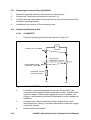
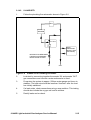
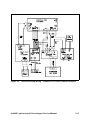
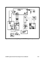
1
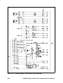
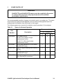
EMISSIONS ANALYSERS
SERVOPRO 1440D1
Light Industrial Gas Analyser
Service Manual
Part Number:
Revision:
Language:
01440002D
5
UK English
This page intentionally blank
01440D1
Light Industrial Gas Analyser
Service Manual
Ref.: 01440/002D/5
Order as part No. 01440002D
This page intentionally blank
Table of Contents
1
INTRODUCTION. . . . . . . . . . . . . . . . . . . . . . . . . . . . . . . . . . . . . . . . . . . . . . . 1.1
1.1 Scope of this Manual . . . . . . . . . . . . . . . . . . . . . . . . . . . . . . . . . . . . . . . 1.1
2
REPAIR . . . . . . . . . . . . . . . . . . . . . . . . . . . . . . . . . . . . . . . . . . . . . . . . . . . . . . 2.1
2.1 Test Equipment and Tools . . . . . . . . . . . . . . . . . . . . . . . . . . . . . . . . . . . 2.1
2.2 Sample condition requirements . . . . . . . . . . . . . . . . . . . . . . . . . . . . . . 2.2
2.3 Servicing the Oxygen Transducer . . . . . . . . . . . . . . . . . . . . . . . . . . . . . 2.3
2.3.1
Replacement of the 1158 Transducer . . . . . . . . . . . . . . . . . . 2.3
2.3.2
Replacement of the measuring Cell . . . . . . . . . . . . . . . . . . . 2.4
2.3.3
Adjusting the Transducer Gain . . . . . . . . . . . . . . . . . . . . . . . 2.6
2.3.4
Replacing the Thermal Fuse Assembly and/or Heater Disc . 2.6
2.4 Servicing the Infrared Transducer . . . . . . . . . . . . . . . . . . . . . . . . . . . . . 2.7
2.4.1
Removal of the Infrared Transducer . . . . . . . . . . . . . . . . . . . 2.7
2.5 Checking the Analogue Outputs and Display. . . . . . . . . . . . . . . . . . . . 2.8
2.5.1
Checking the Zero . . . . . . . . . . . . . . . . . . . . . . . . . . . . . . . . . 2.8
2.5.2
Checking the Span . . . . . . . . . . . . . . . . . . . . . . . . . . . . . . . . 2.9
2.6 Replacing the Flow Sensor (01800925) . . . . . . . . . . . . . . . . . . . . . . . . 2.10
2.7 Replacing the Power Supply Unit (PSU) . . . . . . . . . . . . . . . . . . . . . . . 2.10
2.8 Replacing the Relay/Output PCB (01420906) . . . . . . . . . . . . . . . . . . . 2.11
2.9 Replacing the Main Control PCB (01420915). . . . . . . . . . . . . . . . . . . . 2.11
2.10 Replacing the Front User Interface PCB (01420904) . . . . . . . . . . . . . . 2.12
2.11 Replacing the Led Front Panel display (2553-7332). . . . . . . . . . . . . . . 2.13
2.12 Replacing the infra-red Interface PCB (01415930). . . . . . . . . . . . . . . . 2.13
2.13 Replacing the Internal Pump (S1420940). . . . . . . . . . . . . . . . . . . . . . . 2.14
2.14 Replacement Plumbing Kits . . . . . . . . . . . . . . . . . . . . . . . . . . . . . . . . . 2.14
2.14.1
01440D1FTX . . . . . . . . . . . . . . . . . . . . . . . . . . . . . . . . . . . . 2.14
2.14.2
01440D1STD . . . . . . . . . . . . . . . . . . . . . . . . . . . . . . . . . . . . 2.15
3
SPARE PARTS LIST . . . . . . . . . . . . . . . . . . . . . . . . . . . . . . . . . . . . . . . . . . . 3.1
3.1 Drawings Incluced in the Manual . . . . . . . . . . . . . . . . . . . . . . . . . . . . . . 3.4
01440D Light Industrial Gas Analyser Service Manual.
i
Table of Contents
ii
01440D Light Industrial Gas Analyser Service Manual.
List of Tables
Table 2.1
Table 2.2
Table 3.1
Table 3.2
Table 3.3
Table 3.4
Requirements for Sample Conditions. . . . . . . . . . . . . . . . . . . . . . . 2.2
SW3 Switch Settings . . . . . . . . . . . . . . . . . . . . . . . . . . . . . . . . . . 2.12
Spares for Normal Operation . . . . . . . . . . . . . . . . . . . . . . . . . . . . . 3.1
Spares for General Use . . . . . . . . . . . . . . . . . . . . . . . . . . . . . . . . . 3.2
Spares Infrared Transducers . . . . . . . . . . . . . . . . . . . . . . . . . . . . . 3.3
Spare for Oxygen Transducer . . . . . . . . . . . . . . . . . . . . . . . . . . . . 3.4
01440D Light Industrial Gas Analyser Service Manual.
iii
List of Tables
iv
01440D Light Industrial Gas Analyser Service Manual.
List of Figures
Figure 2.1
Figure 2.2
Figure 2.3
Figure 2.4
Figure 2.5
Figure 2.6
Figure 2.7
Figure 2.8
Figure 2.9
Figure 2.10
Figure 2.11
Figure 2.12
Figure 2.13
Cell Replacement . . . . . . . . . . . . . . . . . . . . . . . . . . . . . . . . . . . . . . 2.4
Transducer Pot Adjustment . . . . . . . . . . . . . . . . . . . . . . . . . . . . . . 2.8
Range Changes and Alarm Function Setting . . . . . . . . . . . . . . . . 2.11
Component Layout, Front Panel PCB (01420904B) . . . . . . . . . . 2.13
01440D1FTX Plumbing Schematic . . . . . . . . . . . . . . . . . . . . . . . 2.14
01440D1STD Plumbing Schematic . . . . . . . . . . . . . . . . . . . . . . . 2.15
Interconnecting Wiring - 01440D1STD Oxygen Analyser . . . . . . 2.16
Interconnecting Wiring - 01440D1STD Carbon Dioxide Analyser 2.17
Interconnecting Wiring - 01440D1FTX Infra-Red Analyser . . . . . 2.18
Interconnecting Wiring - 01440D1FTX Oxygen Analyser. . . . . . . 2.19
Circuit Diagram, Front Panel PCB 01420904B . . . . . . . . . . . . . . 2.20
Circuit Diagram, Front Panel PCB 01420904B . . . . . . . . . . . . . . 2.21
Output Connections . . . . . . . . . . . . . . . . . . . . . . . . . . . . . . . . . . . 2.22
01440D Light Industrial Gas Analyser Service Manual.
v
List of Figures
vi
01440D Light Industrial Gas Analyser Service Manual.
1
INTRODUCTION
1.1
Scope of this Manual
This manual covers the servicing of the Servomex 1440D series of gas analysers.
This range of analysers can measure up to two gases, based on one of two
measurement principles; a Servomex Single Beam Single Wavelength (SBSW)
infrared transducer and a Servomex paramagnetic oxygen transducer.
•
Refer to the QuickStart Manual or the Technical Data Sheet for the latest
technical specification.
•
Addresses for technical assistance and spares are given on the rear cover.
•
For information on installation and operation, please refer to the QuickStart
Manual, reference part number 01440003D
About this Manual
Ref.: 01440/002D/5
Order as part no.: 01440002D
•
This manual includes WARNINGS, CAUTIONS and NOTES, which provide
information relating to the following:
WARNINGS
•
Hazards which could result in personal injury or death.
CAUTIONS
•
Hazards which could result in equipment or property damages.
NOTES
•
Alert the user to pertinent facts and conditions.
01440D Light Industrial Gas Analyser Service Manual.
1.1
WARNING
•
The electrical power used in this equipment is at a voltage high enough
to endanger life. Trained personnel should only perform servicing.
Service training is available from Servomex.
•
Before carrying out servicing or repair the equipment should be
disconnected from the electrical power supply. Tests must be made to
ensure that disconnection is complete. Note that the relay contacts
may be supplied from a separate source of electrical power.
•
It may be necessary to fault find with the electrical power connected.
Where this is necessary extreme caution should be exercised.
•
The analyser may contain toxic, corrosive, flammable or asphyxiant
gases. Flush the analyser pipe work with clean dry air before
commencing work.
1.2
01440D Light Industrial Gas Analyser Service Manual.
2
REPAIR
2.1
Test Equipment and Tools
The following test equipment and tools should be available to personnel responsible
for maintenance and calibration of the analyser.
•
Volt/ohm/milli-amp meter of high input impedance, resolution 0.1mV.
•
Flat blade screwdriver, 6mm width.
•
Soldering iron 25W.
•
De-solder braid or vacuum de-soldering tool.
•
Potentiometer trimming tool.
•
2.5mm AF Allen Key
•
3mm AF Allen Key
•
Open-ended wrench, width across flats 0.45 in (7/16in) British 3/16 nominal,
non-magnetic.
•
Manometer, with a range exceeding 500mm Wg and a bore not exceeding
5mm.
•
Calibration gases:
•
Clean dry nitrogen with an oxygen concentration of less than 0.1% O2.
•
01440D1STD and 01440D1FTX: Clean dry air, nominal concentration 20.9 O2
(for oxygen analysers) or a certified calibration gas with a suitable CO2 content
(for Carbon Dioxide analyser).
•
01440D1FTX only: A certified calibration gas with a suitable CO or CH4
content (for Infra-red analysers).
01440D Light Industrial Gas Analyser Service Manual.
2.1
2.2
Sample condition requirements
Table 2.1
Requirements for Sample Conditions
Dew Point
At least 5°C below ambient temperature.
Temperature
Nominally at ambient temperature.
Inlet / Outlet
connections
Note: do not
restrict analyser
vent
Inlet pressure
Flow Rate
Particulates
01440D1STD
01440D1STD +
BPR
6.4mm (1/4”) OD tube.
01440D1FTX
3.2mm (1/8”) OD tube.
01440D1STD
1 to 10psig (7 to 70kPag).
01440D1STD +
BPR
17 to 20psia (120 to 140kPaa).
01440D1FTX
Typically 0.3kPag (30mmWG) at 200ml/
min.
01440D1STD
1 to 6l/min.
01440D1STD +
BPR
1 to 2l/min.
01440D1FTX
USER LIMITED to 250ml/min. MAXIMUM.
01440D1STD
<3µm (micro meters), an internal,
replaceable, 0.6µm filter is fitted as
standard.
01440D1STD +
BPR
01440D1FTX
01440D1STD
Condition
01440D1STD +
BPR
01440D1FTX
2.2
The user must fit an external filter of
0.6µm.
Must not be flammable, toxic or corrosive,
as well as being clean and oil free.
Must not be corrosive, as well as being
clean and oil free.
01440D Light Industrial Gas Analyser Service Manual.
2.3
Servicing the Oxygen Transducer
WARNING
•
The opening of covers or removal of parts, except those to which
access can be gained by hand, may expose electrical terminals.
Ensure power is disconnected before working on the analyser.
NOTE
•
Due to the strong magnetic field, which exists around the transducer, it
is advisable to remove wristwatches if worn when servicing the oxygen
transducer.
2.3.1
Replacement of the 1158 Transducer
1.
Carefully remove the foam cover from the transducer and disconnect
the 16-way ribbon cable from the transducer, the sample connections
to the cell and the heater and thermal fuse wires from TB2 on front
the panel PCB.
2.
Loosen the 4 off M4 nuts retaining the bracket that the transducer is
located on. Slide the whole assembly to one side and lift out from the
analyser.
With 01440D1FTX versions, when the assembly is free, unsolder the
Yellow and Black wires from the transducer cell connections. Move
the sleeves on the Pink and Grey wires and unsolder them from the
yellow and black wires from the transducer PCB.
3.
Unscrew the transducer from the bracket by the 3 off screws located
on the underside of the bracket, then remove the remaining insulation
and the 3 off M4 pillars.
4.
Remove the thermal fuse and heating element, from the underside of
the transducer, being careful not to damage it.
5.
Installation is the reverse of the removal process. Ensure thermal
fuse and heater are correctly reconnected. For wiring see Figure 2.7
(or 2.10 for FTX version).
With 01440D1FTX versions, the Yellow and Black wires to the cell on
the new transducer must be unsoldered and then resoldered to the
Pink and Grey wires from the Protection PCB (connect Yellow to Pink
and Black to Grey). Replace the sleeves and fit a cable tie to secure
them.
The Yellow and Black wires from the Protection PCB must be
soldered to the transducer cell connections (Yellow to the connection
marked with yellow spot).
01440D Light Industrial Gas Analyser Service Manual.
2.3
6.
The pipe from the outlet of the flow sensor, if fitted, goes to the upper
gas connector on the cell.
7.
Ensure pipework is leak tight. See Section 2.13.1 or 2.13.2.
8.
Calibrate the analyser and check both the analogue output and
display reading. See Section 2.5.
2.3.2
Replacement of the measuring Cell
MAGNET FRAME
YELLOW SPOT
MEASURING CELL
LOCKING DEVICE
MEASURING CELL
Figure 2.1
2.4
Cell Replacement
1.
Remove the Transducer as described in section 2.3.1.
2.
Unsolder the yellow and black wires from the measuring cell and with
an Allen key loosen the cell locking clamp screw. Grip the cell by the
sides and pull the cell out of the magnet frame. (note that the magnet
will exert a very strong holding force on the cell)
3.
The replacement cell must be fitted the correct way up with the yellow
spot connection at the top. With the cell fully home tighten the cell
locking clamp screw and re-solder the wires to the cell with the yellow
wire to the connection marked with the yellow spot.
4.
Refit the transducer, using the ‘O’ rings supplied with the new cell, the
reverse of section 2.3.1, but do not refit the foam cover at this stage.
01440D Light Industrial Gas Analyser Service Manual.
5.
Connect a nitrogen supply to the analyser, flow or pressure rates as
per section 2.2.
6.
Ensure the electrical safety of all parts and power-up the analyser.
SETTING THE ZERO (follows on from cell change procedure)
7.
Set the ZERO on the front panel to mid point (5 turns from either
end).
8.
Adjust the ZERO pot on the top of the transducer, so that the display
reads 0 ± 2% O2.
9.
Set the ZERO on the front panel so that the display reads 0 ± 0.1%
O 2.
SETTING THE SPAN (follows on from setting the zero)
10.
Adjust the FINE SPAN pot on the top of the transducer fully
clockwise. The potentiometer will ‘click’ when it reaches the end.
11.
Adjust the SPAN on the front panel fully clockwise.
12.
Connect an air supply to the analyser, flow or pressure rates as per
section 2.2.
13.
Adjust the COARSE SPAN pot on the top of the transducer, so that
the front panel displays a nominal 120% of air, approximately 25.1%
O 2.
14.
Adjust the SPAN on the front panel fully counter clockwise.
15.
Adjust the FINE SPAN pot on the top of the transducer, so that the
display reads 93% of air, approximately 19.5% O2.
16.
Refit the foam cover from transducer of the transducer and allow the
analyser to stabilise.
17.
Adjust the SPAN on the front panel so that the display reads 20.9 ±
0.1% O2.
01440D Light Industrial Gas Analyser Service Manual.
2.5
2.3.3
Adjusting the Transducer Gain
It may be necessary to adjust the Span of the transducer if the altitude of use
is greater than about 1200m (4000ft) above sea level.
2.6
1.
Carefully remove foam cover from transducer.
2.
Adjust the FINE SPAN pot on the top of the transducer fully
clockwise. The potentiometer will ‘click’ when it reaches the end.
3.
Adjust the SPAN on the front panel fully clockwise.
4.
Connect an air supply to the analyser, flow or pressure rates as per
section 2.2.
5.
Adjust the COARSE SPAN pot on the top of the transducer, so that
the front panel displays a nominal 120% of air, approximately 25.1%
O 2.
6.
Refit the foam cover of the transducer and allow the analyser to
stabilise.
7.
Adjust the SPAN on the front panel so that the display reads 20.9 ±
0.1% O2.
2.3.4
Replacing the Thermal Fuse Assembly and/or Heater Disc
1.
Remove the Transducer as described in section 2.3.1.
2.
If replacing the heater disc, remove the protective backing from the
new heater disc and press firmly onto the base of the transducer.
Ensure transducer base is clean.
3.
Refit transducer as described in section 2.3.1. Refit the foam cover
of the transducer.
4.
After replacing the thermal fuse assembly or heater disc, the
transducer temperature should be re-checked. Connect a voltmeter
to pins 7 and 8 (0V) on SK5. When the instrument has warmed up,
adjust RV1 on control PCB 1420/915 so that the reading is 323
±3mV.
01440D Light Industrial Gas Analyser Service Manual.
2.4
Servicing the Infrared Transducer
WARNING
•
The opening of covers or removal of parts, except those to which
access can be gained by hand, may expose electrical terminals.
Ensure power is disconnected before working on the analyser.
The Infrared transducer in the analyser is non-field serviceable. In the unlikely event
of failure, the transducer should be removed by following the procedure below and
returned to Servomex for repair or replacement.
A list of the IR transducers available is given in Section 3.4.
2.4.1
Removal of the Infrared Transducer
1.
Remove the two M4 nut holding down the interface assembly
01415930.
2.
Carefully ease the interface assembly (01415930) from the pin
connectors on the transducer PCB.
3.
Disconnect the transducer pipes from the sampling system.
4.
Loosen the 4 off M4 nuts retaining the bracket that the transducer is
located on. Slide the whole assembly to one side and lift out from the
analyser.
5.
When the assembly is free, unscrew the transducer from the bracket
by the 3 off screws located on the underside of the bracket.
6.
For the longer “off board” sensors only: slacken the two fixing screws,
which retain the Infrared bench to the side mounting plate. Utilise the
slot on the front fixing to remove the bench without completely
undoing the fasteners.
7.
Remove the transducer PCB by squeezing the catches on the 4 off
PCB mounting supports, and gently pulling the board off the mounts.
8.
Installation of the new transducer is the reverse of the above
procedure.
01440D Light Industrial Gas Analyser Service Manual.
2.7
9.
Transducer pots must be wound fully clockwise, reference Figure 2.2.
SET SPAN AND ZERO
FULLY CLOCKWISE
Figure 2.2
2.5
Transducer Pot Adjustment
Checking the Analogue Outputs and Display.
NOTE
•
Calibration gas accuracy must be taken into consideration when
setting the zero and span. The figures in the following steps assume
pure N2 and either air (for oxygen) or 100% FULL SCALE (Infra-red
transducers) span gas.
Ensure that the analyser has warmed up for at least 1 hour before calibration.
For oxygen units set range to the lowest O2 concentration (usually range 2).
2.8
2.5.1
Checking the Zero
1.
Connect a DVM across pins 8(-ve) and 15(+ve) on SK5.
2.
With nitrogen connected to the inlet at the correct pressure and flow
(see section 2.1), the DVM should read 0.0000V ±0.0001V.
3.
If not then adjust zero control behind flip down door on front panel.
(For oxygen units if zero is not achievable then the coarse zero will
need adjustment. See section 2.3.2. Setting the zero)
4.
The instrument display should read ‘zero’% ±1 least significant digit.
01440D Light Industrial Gas Analyser Service Manual.
5.
If not, check for correct signal and supply voltages at the connector to
the instrument display module.
6.
If these are correct but the instrument display does not read correctly,
the display module may need to be replaced. Note: There is no ‘zero’
adjustment for the display module itself.
7.
To set mA output, connect the DVM across pins 5(-ve) and 12(+ve)
on SK5.
8.
The DVM should read 4.00mA ± 0.02mA.
9.
If not, adjust RV2 on the control PCB (01420915).
2.5.2
Checking the Span
NOTE
•
Set ranges to full scale (or 0-25% oxygen if air is used as the
oxygen span gas).
1.
Connect the DVM to pins 8(-ve) and 15(+ve) on SK5.
2.
Introduce span gas to the inlet at the correct pressure and flow (see
section 2.1), the DVM should read 1.0000V, ±0.0001V.
If the O2 calibration gas is air, at 20.9% purity, then the figure would
be 0.8360V ±0.0001V.
3.
If not adjust span control behind flip down door on front panel. (For
oxygen units if span is not achievable then the gain of the transducer
will need adjustment. See section 2.3.2. Setting the span)
4.
The display should read correct calibration value ± 1 least significant
digit.
5.
If not, adjust RV5 on the front panel PCB (01420904B) so that the
display reads calibration value ±1 least significant digit.
NOTE
•
It is not essential for the output voltage to be exactly 1.0000V.
E.g. if the voltage is 0.9970V then RV5 is adjusted for a display
reading of 99.7 ±0.1.
6.
To set the mA output, connect the DVM across SK5 pins 5(-ve) and
12(+ve).
7.
The DVM should read 20.00 ± 0.02mA, (or 17.38 ± 0.02mA at air
point).
8.
If not adjust RV3 on control PCB (01420915).
01440D Light Industrial Gas Analyser Service Manual.
2.9
2.6
Replacing the Flow Sensor (01800925)
1.
Unscrew both wires from TB4 on relay and output PCB (01420906).
2.
Disconnect inlet and outlet tubes.
3.
Unscrew flow sensor from rear panel assembly.
4.
Installation is reverse of the removal process. (Reconnect to TB4)
5.
The pipe from the AFCD goes to the inlet on the flow sensor.
6.
Ensure pipework is leak tight. (See section 2.14.1 or 2.14.2)
2.7
Replacing the Power Supply Unit (PSU)
WARNING
•
The opening of covers or removal of parts, except those to which
access can be gained by hand, may expose electrical terminals.
Ensure power is disconnected before working on the analyser.
1.
If necessary remove the transducer to improve access (See Section 2.3.1 for
the oxygen transducer or Section 2.4.1 for the infrared transducers). Note: For
oxygen transducers it is only necessary to disconnect the thermal fuse and
heating coil at TB2 on control PCB.
2.
Remove the vented metal cover from over the power supply.
3.
Disconnect mains power cable and the power cable to the control PCB at the
power supply.
4.
Power supply variants
i) For analysers fitted with an old version power supply (MAP40 or FLU3-403AD). Remove the hexagonal spacers and power supply.
ii) For latest version power supplies (Emerson LPT63) unscrew the 4 off M4
waisted screws holding power supply and cover mounting brackets and
remove brackets and power supply.
5.
6.
7.
2.10
Installation is for power supply type Emerson LPT63 only.
i) Fit shakeproof washers to waisted M4 screws and screw through power
supply pcb, from component side.
ii) Position mounting brackets with individual lugs on copper side of supply pcb.
iii) Secure power supply and brackets to analyser chassis using m4 waisted
screws.
iv) Re-connect mains and control connector to power supply pcb, fit grommets
to new power supply cover and secure cover to brackets.
Ensure pipework is leak tight. See Sections 2.14.1 or 2.14.2.
Calibrate the analyser as described in the Operator Manual and check both
the analogue output and display reading. See Section 2.5.
01440D Light Industrial Gas Analyser Service Manual.
2.8
Replacing the Relay/Output PCB (01420906)
1.
Disconnect the flow sensor wires from TB4 and undo the four hexagonal fixing
sets located adjacent to the 15 way ‘D' connectors.
1.
Disconnect the lower 34 way ribbon connector from the front panel PCB.
2.
Disconnect the 16 way ribbon connector at the transducer.
3.
The Relay/Output PCB may now be replaced, installation is the reverse of the
removal process, ensure all connections are remade (including the link across
TB4, 01440D1FTX only).
2.9
Replacing the Main Control PCB (01420915)
1.
If necessary remove the transducer and power supply to improve access (See
Section 2.3.1 for oxygen transducer or 2.4.1 for infrared transducer).
2.
Disconnect all connections to the display, noting their positions.
3.
Undo the M3 screws and lift the PCB off of the three self-clinching spacers.
4.
Fit new control PCB, TRANSFER LINK SETTINGS for ranges and alarms
(reference Figure 2.3).
5.
Infra-red units only; it will be necessary to utilise links from the old PCB. Range
1 must be set to 100, range 2 must be linked across 10, 20 and 50).
6.
Installation is the reverse of the removal process. Ensure spacers are
positioned correctly between boards.
ALARM ‘OFF’
ALARM ‘HI’
ALARM ‘LOW’
Figure 2.3
Range Changes and Alarm Function Setting
01440D Light Industrial Gas Analyser Service Manual.
2.11
2.10
Replacing the Front User Interface PCB (01420904)
1.
Remove the main control PCB, refer to section 2.9.
2.
Disconnect the display ribbon cable.
3.
Undo the five screws which retain the PCB.
4.
Before installing new control PCB, transfer the switch settings for the display
(reference Table 2.2 and Figure 2.4).
5.
Replace the front panel PCB, paying particular attention to the alignment of the
LED's associated with the function switches and bezels. Before tightening the
fixing screws, ensure that the switches operate without ‘sticking'.
6.
Installation is the reverse of the removal process. Ensure spacers are
transferred from old PCB as required.
Table 2.2
SW3 Switch Settings
Measurement
SW3 Settings
1
2
3
4,5,6
7
8
100% O2, CO2 & CH4
ON
OFF
OFF
OFF
OFF
OFF
50% CO2, CO & CH4
ON
OFF
OFF
OFF
ON
OFF
25% CO2, CO & CH4
ON
OFF
OFF
OFF
OFF
ON
10% CO2 & CO
OFF
ON
OFF
OFF
OFF
OFF
5% CO2 & CH4
OFF
ON
OFF
OFF
ON
OFF
2.5% CO2 & CO
OFF
ON
OFF
OFF
OFF
ON
1% CO2 & CO
OFF
OFF
ON
OFF
OFF
OFF
0.5% CO2
OFF
OFF
ON
OFF
ON
OFF
0.25% CO2
OFF
OFF
ON
OFF
OFF
ON
2.12
01440D Light Industrial Gas Analyser Service Manual.
RED
ORANGE
BROWN
BROWN
ORANGE
RED
Figure 2.4
Component Layout, Front Panel PCB (01420904B)
2.11
Replacing the Led Front Panel display (2553-7332)
1.
Remove the front panel PCB’s, reference sections 2.9 and 2.10.
2.
Undo the four corner screws on the LED module to replace.
2.12
Replacing the infra-red Interface PCB (01415930)
1.
Remove the two M4 screw holding down the interface PCB, 01415930.
2.
Carefully ease the interface from the pin connectors on the transducer PCB.
3.
Disconnect the connectors that go between the interface PCB to the control
panel PCB.
4.
Installation is the reverse of the removal process.
01440D Light Industrial Gas Analyser Service Manual.
2.13
2.13
Replacing the Internal Pump (S1420940)
1.
Disconect the pump switch at the front panel of the analyser.
2.
Remove the Transducer as described in section 2.3.1.
3.
Cut the cable ties holding down the pump and lever the pump and pads off the
tranducer mounting bracket.
4.
Installation is the reverse of the removal process.
2.14
Replacement Plumbing Kits
2.14.1
01440D1FTX
1.
Follow the plumbing flow schematic shown in Figure 2.5.
CELL
3.2MM (1/8”) OD TUBES
FLOW RATE
100ML/MIN. TYPICAL
GAS CONNECTIONS
3.2MM (1/8”) OD TUBE
EXTERNAL FILTER
(NOT SUPPLIED)
IN
Figure 2.5
2.14
OUT
01440D1FTX Plumbing Schematic
2.
Leak test by connecting together the sample 'IN' and 'OUT' gas
connections and connect a water manometer to them. Pressurise the
system to approx. 500mm water gauge and leave to stabilise. No
change in manometer level should be detected once the reading has
stabilised.
3.
If a leak exists, check connections using a soap solution (max.
internal pressure 10psig). This testing should also include the oxygen
cell and its window.
4.
Rectify leaks and re-check.
01440D Light Industrial Gas Analyser Service Manual.
2.14.2
01440D1STD
1.
Follow the plumbing flow schematic shown in Figure 2.6.
CELL
FLOW
SENSOR
A.F.C.D
OUT
BACK
PRESSURE
REGULATOR
(OPTIONAL)
RESTRICTOR REQUIRED
FOR BACK PRESSURE
REGULATOR OPTION
IN
Figure 2.6
OUT
01440D1STD Plumbing Schematic
2.
Leak test by connecting together the sample 'IN' and sample 'OUT'
gas connections and connect a water manometer to them.
3.
Pressurise the system to approx. 500mm water gauge and leave to
stabilise. The leak rate should be less than 2mm/min. after the level
has initially stabilised.
4.
If a leak exists, check connections using a soap solution. This testing
should also include the oxygen cell and its window.
5.
Rectify leaks and re-check.
01440D Light Industrial Gas Analyser Service Manual.
2.15
Figure 2.7
2.16
Interconnecting Wiring - 01440D1STD Oxygen Analyser
01440D Light Industrial Gas Analyser Service Manual.
Figure 2.8
Interconnecting Wiring - 01440D1STD Carbon Dioxide Analyser
01440D Light Industrial Gas Analyser Service Manual.
2.17
Figure 2.9
2.18
Interconnecting Wiring - 01440D1FTX Infra-Red Analyser
01440D Light Industrial Gas Analyser Service Manual.
Figure 2.10 Interconnecting Wiring - 01440D1FTX Oxygen Analyser
01440D Light Industrial Gas Analyser Service Manual.
2.19
Figure 2.11 Circuit Diagram, Front Panel PCB 01420904B
2.20
01440D Light Industrial Gas Analyser Service Manual.
Figure 2.12 Circuit Diagram, Front Panel PCB 01420904B
01440D Light Industrial Gas Analyser Service Manual.
2.21
Figure 2.13 Output Connections
2.22
01440D Light Industrial Gas Analyser Service Manual.
3
SPARE PARTS LIST
WARNINGS
•
01440D1FTX and 01440D1STD spares must be supplied by Servomex
to comply with personnel safety requirements and to maintain
performance specification.
The recommended quanitity of spares to be held in stock, is a guide only. The exact
requirement for spare parts will depend upon the reliance being placed upon the
analyser and the distance from Servomex or their agent
The following spares are required to maintain normal operation of the analyser.
Table 3.1
Spares for Normal Operation
Recommended qty.
Part
Number
Description
No. of analysers
1-3
4-9
10+
S1400990
AC supply fuse kit.
10 off (T) 2A (Used in single
measurement units)
10 off (T) 3.15A (Used in dual
measurement units)
2
4
6
S1800985
AFCD filter element kit (10 off filters).
01440D1STD only.
1
2
2
2323-7029
Viton O’ ring for sealing filter element in
AFCD.
1
2
3
5984-7706
Back Pressure Regulator, if fitted.
01440D1STD only.
1
1
2
5981-0593
O’ ring for oxygen transducer, if fitted.
Two required per transducer.
2
4
10
01440D Light Industrial Gas Analyser Service Manual.
3.1
The following spares are also available for the analyser.
Table 3.2
Spares for General Use
Recommended
qty.
Part
Number
Description
No. of analysers
1-3
4-9
10+
S1420904B
Front ‘switching’ PCB.
0
0
1
2726-4119
Span or zero potentiometer.
0
1
2
S1420915
Control PCB.
0
0
1
S1420906
Alarm relay PCB.
0
1
1
210198
Power supply Unit
0
0
1
S1440922
Power supply Assembly
(for 2811-2011 replacement only)
0
0
1
255-7332
LED display, 3 1/2 digits.
0
0
1
S1420935
Automatic flow control device.
0
0
1
01800925
Flow sensor assembly. 01440D1STD only.
0
0
1
2653-2518
Heater Disc for oxygen transducer only.
0
0
1
01420928
Thermal fuse assembly for oxygen
transducer only.
0
1
2
01415930
Interface PCB for IR modules only.
0
1
2
S1420940
Pump replacement kit, if fitted.
1
2
4
S1420941
Viton Pipe-work kit, 01440D1STD only.
1
2
2
S1420942
Stainless steel pipe-work kit, 01440D1FTX
only, oxygen transducer.
1
2
2
Stainless steel pipe-work kits, 01440D1FTX
only, infra-red transducers. See Table 3.3.
1
2
2
Protection PCB
1
2
2
S1420943
S1420944
S1420945
01420908
3.2
01440D Light Industrial Gas Analyser Service Manual.
Table 3.3
Part
Number
Spares Infrared Transducers
Description
Spare Pipework Kit
Recommended
qty.
No. of analysers
1-3
4-9
10+
01520709
0 - 0.25% CO2 transducer.
S1420943
0
0
1
01520708
0 - 0.5% CO2 transducer.
S1420943
0
0
1
01520707
0 - 1% CO2 transducer.
S1420944
0
0
1
01520706
0 - 2.5% CO2 transducer.
S1420945
0
0
1
01520705
0 - 5% CO2 transducer.
S1420945
0
0
1
01520704
0 - 10% CO2 transducer.
S1420945
0
0
1
01520703
0 - 25% CO2 transducer.
S1420945
0
0
1
01520702
0 - 50% CO2 transducer.
S1420945
0
0
1
01520701
0 - 100% CO2 transducer.
S1420945
0
0
1
01522707
0 - 1% CO transducer.
(01440D1FTX Only).
S1420943
0
0
1
01522706
0 - 2.5% CO transducer.
(01440D1FTX Only).
S1420943
0
0
1
01522704
0 - 10% CO transducer.
(01440D1FTX Only).
S1420945
0
0
1
01522703
0 - 25% CO transducer.
(01440D1FTX Only).
S1420945
0
0
1
01522702
0 - 50% CO transducer.
(01440D1FTX Only).
S1420945
0
0
1
01521705
0 - 5% CH4 transducer.
(01440D1FTX Only).
S1420944
0
0
1
01521703
0 - 25% CH4 transducer.
(01440D1FTX Only).
S1420945
0
0
1
01521702
0 - 50% CH4 transducer.
(01440D1FTX Only).
S1420945
0
0
1
01521701
0 - 100% CH4 transducer.
(01440D1FTX Only).
S1420945
0
0
1
01440D Light Industrial Gas Analyser Service Manual.
3.3
Table 3.4
Spare for Oxygen Transducer
Recommended qty.
Part
Number
Description
No. of analysers
1-3
4-9
10+
01158000
Oxygen Transducer
0
0
1
00325000
Measuring Cell
0
1
1
3.1
Drawings Incluced in the Manual
Circuit Diagram of Control Board 01422911: Relevant drawing 01422/111, is
enclosed.
3.4
01440D Light Industrial Gas Analyser Service Manual.