1
Eaton® Fuller ® Clutches
Failure Analysis Guide
All Clutch Models
Troubleshooting Guide CLTS-1271 June 2003
For the most current information, visit the Roadranger web site at www.roadranger.com
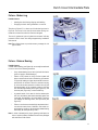
Introduction
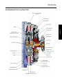
Clutch Diagrams
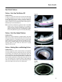
Easy-Pedal Heavy Duty Clutch
Introduction
Solo Adjustment-Free Heavy Duty Clutch
Introduction
Table of Contents
Introduction
Clutch Diagrams.......................................................... 1
Factors that Effect Clutch Performance ....................... 1
Clutch Cover/Intermediate Plate
Clutch Cover/Intermediate Plate Failures..................... 3
Clutch Disc Assembly
Clutch Disc Assembly Failures .................................. 15
Adjusting Mechanisms and
Clutch Brakes
Adjusting Mechanism and Clutch Brake Failures....... 24
Solo Clutch
Solo Clutch Failures .................................................. 25
Miscellaneous
Miscellaneous Failures .............................................. 27
Pilot Bearing
Pilot Bearing Recommendations ............................... 30
Troubleshooting
Clutch Troubleshooting ............................................. 31
Glossary
Clutch Glossary ......................................................... 39
Introduction
Factors that Effect Clutch Performance
The major cause of clutch failure can be summarized with two words: “EXCESSIVE HEAT”. Extreme operating temperatures (excessive heat) can cause the clutch to fail because the heat generated between the flywheel, driven discs, intermediate plate, and
pressure plate are high enough to cause the metal to flow and the friction material to be destroyed.
Heat or wear is practically nonexistent when a clutch is fully engaged. But, during the moment of engagement (when the clutch is
picking up the load), it generates considerable heat. An improperly adjusted or slipping clutch will generate sufficient heat to rapidly self-destruct.
Proper training of drivers and mechanics can go a long way toward extending clutch life. Anyone who drives the truck, whether
on or off highway, should learn how to operate the vehicle properly. The most critical points to cover in driver training programs
are: learning to start in the right gear, proper clutch engagement, recognizing clutch malfunctions, and recognizing the need for
readjustment.
The most important areas to cover in the training programs that can affect clutch performance are:
STARTING THE VEHICLE IN THE PROPER GEAR
An empty truck can be started satisfactorily in a higher transmission gear ratio than when partially or fully loaded. If auxiliary transmissions or multi-speed axles are used, they must be in the lower ratios for satisfactory starts. Drivers should be shown what
ratios can be used for safe starts when the truck is empty or loaded. Do not let the driver find out for himself; he can burn up the
clutch by this experimentation. If the truck is diesel powered, a good rule of thumb for the driver to follow is: empty or loaded,
select the gear combination that lets you take up the slack and start moving out with an idling engine or, if necessary, just enough
throttle to prevent stalling the engine. After the clutch is fully engaged, the engine should be accelerated for the upshift into the
next higher gear.
GEAR SHIFTING TECHNIQUES
Many drivers upshift into the next gear-or even skip-shift into a higher gear-before the vehicle has reached the proper speed. This
type of shifting is almost as damaging as starting off in a gear that is too high, since the engine speed and vehicle speeds are too
far apart, requiring the clutch to absorb the speed difference as heat (excessive slippage).
EXCESSIVE VEHICLE OVERLOAD OR OVERLOADING THE CLUTCH
Clutches are designed and recommended for specific vehicle applications and loads. These limitations should not be exceeded.
Excessive or extreme overloading can not only damage the clutch, but the entire vehicle power train as well. If the total gear reduction in the power train is not sufficient to handle excessive overloads, the clutch will suffer, since it is forced to pick up the load
at a higher speed differential.
RIDING THE CLUTCH PEDAL
This practice is very destructive to the clutch since a partial clutch engagement permits slippage and excessive heat. Riding the
clutch pedal will also put a constant thrust load on the release bearing, which can thin out the lubricant and also cause excessive
wear on the pads. Release bearing failures can be attributed to this type of operation.
HOLDING THE VEHICLE ON AN INCLINE WITH A SLIPPING CLUTCH
This procedure uses the clutch to do the job normally expected of the wheel brakes. A slipping clutch accumulates heat faster than
it can be dissipated, resulting in early failures.
COASTING WITH THE CLUTCH RELEASED AND TRANSMISSION IN GEAR
This procedure can cause high driven disc R.P.M. through multiplication of ratios from the final drive and transmission. It can
result in “throwing” the facing off the clutch discs. Driven disc speeds of over 10,000 R.P.M. have been encountered in such simple procedures as coasting tractors down an unloading ramp. While an ample safety factor is provided for normal operation, the
burst strength of the facing is limited.
1
Service Procedure
Maintenance personnel may want to attend driver training programs to see what driver misuse can do to clutch life. This training
will place them in a better position to spot and analyze failures during their clutch maintenance programs.
Introduction
ENGAGING CLUTCH WHILE COASTING
This procedure can result in tremendous shock loads and possible damage to the clutch, as well as the entire drivetrain.
REPORTING ERRATIC CLUTCH OPERATION PROMPTLY
Drivers should report erratic clutch operation as soon as possible, to give the maintenance personnel a chance to make the necessary inspection, internal clutch adjustment, linkage adjustments, lubrication, etc., thereby avoiding possible clutch failures and
breakdowns while on the road. The importance of free-pedal travel (sometimes referred to as pedal lash) should be brought to the
driver’s attention as well as the mechanic. This item should be included and commented on daily in the driver’s report, since clutch
free-pedal is the maintenance personnel’s guide to the condition of the clutch and the release mechanism.
CLUTCH ADJUSTMENTS
Drivers and mechanics should be made aware of the fact that Eaton Fuller Angle-Spring and Easy-Pedal Clutches have provisions
for an internal clutch adjustment. This permits the clutch “itself” to be readjusted while it is in the vehicle. Details of the clutch
adjustment are covered in the Eaton Fuller Installation Instructions packaged with each clutch assembly.
When drivers and mechanics are properly trained, there are still certain problems that may occur. The following failure analysis
and troubleshooting guide lists some common problems, their causes, and suggested corrective action. Note that some of these
problems relate back to the previous discussion on poor driving and maintenance techniques.
2
Clutch Cover/Intermediate Plate
Clutch Cover/Intermediate Plate Failures
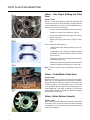
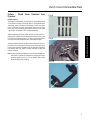
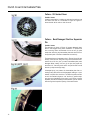
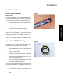
Failure - Yoke Bridge Rubbing into Cover
Possible Causes
The arrows in Figures 1 and 2 show the areas of contact between
the release yoke bridge and the clutch cover. Overstroking of the
yoke, in an attempt to obtain the required 1/2’’ - 1’’ clutch brake
squeeze, is a typical cause of this failure.
The reason that normal clutch brake squeeze cannot be obtained
may be due to one or more of the following situations:
Worn clutch brake
•
Broken or missing clutch brake
•
Worn or incorrect transmission bearing retainer cap
(refer to Figure 3)
•
Excessive wear on release bearing wearing pads and/or
the fingers of the yoke (refer to Figure 1)
•
lmproper set up of the linkage system. Consult your
OEM service manual
•
Incorrect yoke installed
Clutch Cover/Intermediate Plate
•
Note: The clutch cover can be reused if the above items are corrected, a new yoke is installed, and there are no broken or
cracked parts on the cover. The above failure is typically
preceded by a noise complaint and/or vibrating clutch pedal
at the point where the clutch pedal is fully depressed. Depending upon the amount of wear (at the bearing cap and/
or yoke fingers/wear pads), it may be possible to adjust the
linkage to eliminate the noise complaint.
TRANSMISSION BEARING RETAINER CAP
Dimension A, based on SAE standards, is 8.657” (219.9 mm)
nominal, and should not be greater than 8.71” (221.5 mm) Ref.
1990 S.A.E. handbook 4:36.106
3
Clutch Cover/Intermediate Plate
Fig 4
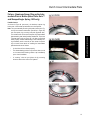
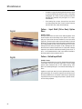
Failure - Yoke Fingers Rubbing into Clutch
Cover
Possible Causes
Figures 4 - 5 show the damage that results when the release yoke
contacts the clutch cover. More specifically, the fingers have become pinched between the clutch cover and release bearing, resulting in one or more of the following:
•
A broken /cracked release bearing housing (not shown)
•
Damage to the clutch cover (see arrows, Figure 4)
•
Wear to the backside of the yoke fingers (see arrows in
Figure 5, top yoke)
•
Broken yoke finger(s) (see arrow in Figure 5 bottom
yoke)
Some causes of the above failure are:
Fig 6
•
Linkage system broke, allowing the loose yoke to contact cover
•
Linkage system was improperly reinstalled (example:
forgetting to reinstall the cotter key, allowing the clevis
pin to come out)
•
Adjusting the clutch with the linkage instead of internally using the adjusting ring
•
Rotating the ring the wrong direction (counterclockwise
instead of clockwise) when adjusting for clutch wear
Note: The above conditions may be preceded by a noise complaint.
Failure - Cracked/Broken Clutch Cover
Possible Causes
Referring to the arrow in Figure 6, this brand new clutch (EasyPedal 1402 S.D.) was damaged during transmission installation.
More specifically, the release yoke “fingers” were elevated to the
“straight out position” and were allowed to jam into the clutch
cover. Subsequent damage might be a broken finger(s)(Figure 5)
or bent release yoke / cross shafts. As a result, it is important that
these parts be inspected for damage (and replaced if damaged)
before installing a new clutch.
Failure - Broken Retainer Assembly
Possible Causes
Figure 7 shows what can happen when the levers break through
the retainer’s nose. The primary cause of this failure is allowing
the transmission to hang unsupported in the driven disc during
transmission installation.
4
Clutch Cover/Intermediate Plate
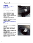
Failure - Clutch Cover Detached from
Flywheel
Fig 8
Possible Causes
The broken mounting bolts, show in Figure 8, are the direct result
of insufficient torquing of these (8) bolts to the flywheel. More
specifically, these bolts were loose enough to allow the clutch
cover to hammer back and forth against each bolt until they
broke. Also, the (8) mounting bolt holes in the clutch cover were
“egg-shaped” as a result of the constant hammering.
Clutch Cover/Intermediate Plate
Additional damage occurred to both the clutch cover and the release yoke as a result of their interference with each other (refer
to the arrows in Figures 9 and 10). It is worth noting that this service clutch had accumulated 50,000+ miles before it failed.
Fig 9
Another potential cause of the above failure would be the overtorquing of the mounting bolts. Doing so can cause the bolts to
fracture and eventually separate from the flywheel. Combining
this scenario with low grade mounting bolts will increase the
chances of failure.
Note: Refer to the Eaton Installation Instructions (packaged with
each clutch) to determine the proper mounting bolt torque,
minimum grade of bolt, etc., for the specific Eaton Fuller
Clutch model you are installing.
Fig 10
5
Clutch Cover/Intermediate Plate
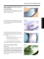
Fig 11
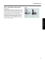
Failure - Damaged Sleeve Bushing
Possible Causes
Failure to center the input shaft with the sleeve of the release
bearing assembly, when installing the transmission, can cause
this failure. If the transmission hangs up during installation, investigate the cause before preceding as excessive force can damage the bushing (see arrow in Figure 12). Allowing the
transmission to hang unsupported in the sleeve bushing can
damage the bushing. The arrow in Figure 11 shows another example of sleeve bushing damage on a heavy duty clutch.
Fig 12
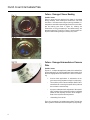
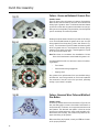
Failure - Damaged Intermediate or Pressure
Plate
Possible Causes
Figures 13 - 16 depict damaged clutch plates which resulted from
an abnormal amount of clutch slippage/heat. Some causes of this
abnormal slippage/excess heat can be one or more of the following:
1.
Incorrect clutch applications. In otherwords, the engine’s torque rating exceeds the clutch’s torque rating.
•
Driver abuse. (refer to Factors that Effect Clutch Performance Sections concerning the specific driver practices
that can lead to excessive heat).
•
Improper/ inadequate clutch adjustments. More specifically, operating the truck without free-play for extended
periods of time; adjusting the clutch via the linkage instead of the required internal adjustment.
•
Overloading of the vehicle.
Figure 13 is an example of a cracked pressure plate. The heat flow
was so great that the metal could not dissipate it quickly enough.
6
Clutch Cover/Intermediate Plate
Failure - Damaged Intermediate of Pressure
Plate (Continued)
Possible Causes (Continued)
Figure 14 shows a broken intermediate plate. As in the previous
example, the heat flow was so intense that the metal could not
disperse the heat quickly enough.
Clutch Cover/Intermediate Plate
In Figure 15, an area of the intermediate plate has been circled to
reveal the damage of heat checks. These heat checks are actually
small cracks with raised ridges that are capable of shaving off the
facings of the driven disc.
Finally, Figure 16 reveals an example of a burned or scorched intermediate plate in which the metal became so hot that it began
to flow. The typical evidence of such a failure will be one or more
of the following:
•
High and low spots on the plate
•
Partial transfer of the facing material (ceramic or organic) from the driven disc onto the plate
•
A blue discoloration throughout the failed part
To view the resulting damage that can occur to the facing material of the driven discs, please refer to Figures 53-56 and 58.
Failure - Grooved Pressure Plate
Possible Causes
The groove (see arrow in Figure 17) worn into the face of this
pressure plate was caused by the rivets of the driven disc facing.
(For the related disc failure, see the description under Figure 70).
The same damage can occur on both the intermediate plate and
flywheel. A surface that is grooved can damage the new driven
discs that are installed. As a result, a new clutch assembly should
be installed. Refer to the OEM service manual concerning flywheel resurfacing.
7
Clutch Cover/Intermediate Plate
Failure - Cocked Drive Pins (14" Pot-Style
Clutches Only)
Possible Causes
The groove worn in the face of the drive pin slots are on the upper
section of the face on one side of the slot (see arrow in Figure 18)
and on the lower section on the opposite side of the slot. This indicates that the drive pins were cocked and causing the intermediate plate to hang-up. This will cause release problems and
therefore hard shifting. Do not file the slots of the intermediate
plate to correct the problem. Instead, you must reset the drive
pin(s) until they are square to the flywheel.
Note: Always install new Eaton drive pins when installing a new
Eaton Fuller 14” Heavy Duty Clutch. This is important because worn drive pins (against the new intermediate plate
slots) can prevent the clutch from releasing cleanly. Also,
ensure that the drive pins are set squarely to the flywheel’s
friction surface (refer to the Eaton Installation Instrutions
packaged with each Eaton Fuller Clutch). Failure to set each
drive pin squarely is the most prevalent reason for a “poor
release complaint” on a recently installed clutch (Angle
Spring and Easy-Pedal Plus 1402).
Failure - Filed Drive Slots
Possible Causes
As indicated by the shiny areas on the drive slots, (see arrow Figure 19) the slots of this intermediate plate were hand filed. Eaton
does not recommend this practice since it can cause unequal
loading on the drive pins in the flywheel. Instead, Eaton recommends that the drive pins be checked for squareness to the flywheel friction surface and reset if necessary (see Eaton
Installation Instructions).
8
Clutch Cover/Intermediate Plate
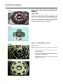
Failure - Broken Drive Pins and Worn/Broken
Drive Slots (14" Pot-Style Clutches Only)
Fig 20
Possible Causes
Figure 20 shows a broken drive pin head that has become
wedged into the intermediate plate’s drive slot. Figure 21 is the
same intermediate plate but with excessively worn and broken
drive slots. Figure 22 shows a broken drive pin. The above failures can be caused by one or more of the following:
Failure to use the anti-rattle springs packaged with each
super-duty clutch
•
Misapplication of the clutch
•
Unequal loading on the drive pins as a result of filing the
drive slots.
Clutch Cover/Intermediate Plate
•
Fig 21
Note: Failure to use the anti-rattle springs can cause other problems such as a noisy or poor releasing clutch.
Fig 22
9
Clutch Cover/Intermediate Plate
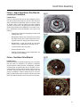
Fig 23
Failure - Anti-Rattle Springs Installed Backwards
Possible Causes
As shown in Figures 23 and 24, the intermediate plate was “hanging up” at the corners of the open sections of the anti-rattle
springs. The driver’s complaint was a clutch that would not release. It is important that the rounded sections of the anti-rattle
springs be installed TOWARDS the flywheel/ engine.
Fig 24
Failure - Interference Between Retainer Assembly and Rear Disc Rivets
Possible Causes
Figure 25 shows the damage done to the nose of the retainer assembly (see arrow) due to contact with the disc rivets. Figure 57
shows the resulting damage done to the rear disc. Adjusting the
clutch externally (with the linkage) instead of internally (rotation
of adjusting ring) will cause the retainer
sleeve/release bearing assembly to move too far forward as the
clutch wears, leading to this failure.
An additional result from the above failure is that while the clutch
is engaged, it can begin to slip due to the unloading condition
created by the disc and retainer interference. This, in turn, will
create excessive heat and can cause the pressure plate to break
(see Figure 25, black arrow on pressure plate) and /or the ceramic buttons to separate from the disc (see Figure 58). The above
failure may also be preceded by a noise complaint.
10
Clutch Cover/Intermediate Plate
Failure - Broken Leg
Possible Causes
•
Abusing the clutch during shipping and handling.
•
Dropping the clutch during installation or removal.
The photo in Figure 27 is a close-up of the broken leg shown in
Figure 26. The arrow in this close-up shows where the leg contacted the concrete floor after the clutch was dropped.
Clutch Cover/Intermediate Plate
The use of “guide studs” plus a “hydraulic clutch stand” will help
prevent this 150 lb. clutch from being dropped during installation
and removal.
Note: Eaton Clutch does not provide warranty coverage for this
type of failure.
Failure - Release Bearing
Possible Causes
A failed release bearing (see Figure 28) can usually be attributed
to one or more of the following situations:
•
A dry release bearing due to lack of periodic lubrication
(does not apply to sealed bearings).
•
Failure to fully release or riding the clutch pedal will
place a constant thrust load on the bearing, (see arrows
in Figure 29) leading to higher temperatures and consequential loss of lubricant. Failure to maintain free play
up in the cab can also cause this condition. Not only will
the bearing begin to fail, constant contact in this area
will cause both the release yoke fingers (Figure 79), and
the wear pads (Figure 29), to wear excessively.
•
A potential result of this wear is that the release yoke
will force the bearing and sleeve assembly against the
input shaft. Consequently, this “side loading” condition
can damage the bushing, sleeve, and input shaft (see
Figure 78).
•
Failure to use the recommended high temperature lubricant can also cause a loss of lubricant, even under normal operating conditions. An impending release bearing
failure may be accompanied by noise.
Note: In order to determine the proper greasing techniques, be
sure to consult the Eaton Installation Instructions packaged
with each Eaton Fuller Clutch.
11
Clutch Cover/Intermediate Plate
Failure - Oil Soaked Cover
Possible Causes
A leaking transmission or a leaky rear main engine seal can coat
the clutch cover with oil, as indicated in Figure 30. Figure 41
shows the disc which was run with this cover.
Failure - Bent/Damaged Positive Separator
Pin
Possible Causes
The separator pin shown in Figure 31 became damaged (bent)
when it was dropped during clutch installation. To prevent this
from occurring, Eaton recommends the use of two (2) guide
studs when mounting the intermediate plate and clutch cover to
the flywheel (refer to the Eaton Installation Instructions).
The damage done to the separator pins in Figures 32 and 33 (see
arrows) is the result of using the wrong tool combined with excessive force. All four pins (on each intermediate plate) were
damaged. When “setting” the four (4) roll pins, the proper tool
would be a 1/4” flat nose punch used in conjunction with a small
hammer (to help ensure light taps).
A damaged pin(s) can prevent the intermediate plate from retracting evenly when the clutch is disengaged, leading to a “poor
release” complaint from the driver. The same complaint can also
occur if the mechanic forgets to “set” the four (4) positive separator pins upon installation of the clutch. In you forgot to set the
separator pins before installing the transmission, you can still set
them through the inspection opening of the transmission.
12
Clutch Cover/Intermediate Plate
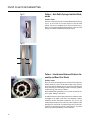
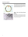
Failure - Aluminum Spacer Ring on the Intermediate Plate is Broken (Eaton Fuller Solo ™
and Stamped Angle Spring 1402 only)
Possible Causes
As shown in Figure 34 (see arrow), the aluminum spacer ring
broke when it was bolted up backwards onto the flywheel.
•
A clutch that will not release properly.
•
The release bearing position may be closer than normal
to the transmission bearing retainer cap immediately
upon clutch installation.
•
A “cracking” noise as you tighten the (8) mounting
bolts that secure the cover to the flywheel.
Clutch Cover/Intermediate Plate
Note: The cover assembly mounting hole pads (see arrow in Figure 35) have made an indentation (see arrow in Figure 36)
onto the spacer ring mounting hole pads (flywheel side).
This evidence will confirm that the spacer ring/intermediate
plate assembly was indeed installed backwards. The words
“Flywheel side" (refer to Figure 37) will face the flywheel
when properly installed. Mishandling of this assembly during installation and/or removal can also cause the spacer
ring to break. Some results of installing the intermediate
plate backwards are as follows:
13
Clutch Cover/Intermediate Plate
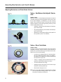
Failure - Lever Wear
Possible Causes
As indicated by arrows in Figure 38, excessively worn levers are
most likely the result of lack of maintenance. More specifically,
lever wear can be the result of one or more of the following conditions:
•
A dry, seized, or broken throw out bearing. Typical
causes of a damaged bearing are:
a.
Operating the truck without free-play
b.
Constant riding of the clutch pedal
Both items 1 and 2 can cause the thinning and loss of bearing lubricant. They can also cause rapid lever wear due to constant
contact with the bearing.
•
A throw out bearing which fits too tightly on the front
bearing cap stem. As a result, the return spring(s) (attached to the linkage or throw-out bearing) may not be
capable of retracting the throw-out bearing away from
the clutch levers. This will cause contact between these
parts.
•
Worn and/or binding linkages are causing the throw-out
bearing to make “constant contact” with the clutch’s
three (3) release levers (Figure 38).
•
Using a throw out bearing of inferior quality.
Failure - Adjusting Linkage to Compensate
for Clutch Wear
Possible Causes
Figure 39 shows the back of the pressure plate. This clutch has
been properly adjusted (internally, using the adjusting ring) because each of the 6 levers has more than one witness mark (or
lever fulcrum point).
Figure 40 depicts a clutch that has not been adjusted properly. As
shown, there is only one witness mark per lever indicating that
the clutch was improperly adjusted using the linkage.
WARNING: Continually adjusting for clutch wear via the
linkage can lead to the failures shown in Figures 4, 5,
25, and 57-58.
14
Clutch Disc Assembly
Clutch Disc Assembly Failures
Failure - Oil Soaked Ceramic Disc
Possible Causes
After removal from the truck, the top half of this ceramic disc
(Figure 41) was cleaned in order to reveal the contrast with the
bottom half which is still oil soaked (Figure 30 shows the clutch
cover that was run with this disc). Possible contributors to this
condition are a leaking transmission and/or a leaking rear main
engine seal.
Clutch Disc Assembly
Furthermore, oil on the disc buttons can cause the clutch to release poorly due to increased drag, and/or chatter/slip during engagement.
Note: Eaton does not recommend the reinstallation of any discs
that are oil soaked because the button facings cannot be
satisfactorily cleaned.
Failure - None
Normal Wear Patterns
When troubleshooting Eaton Fuller Clutches, do not be concerned with the wear pattern (darkened areas) of the disc buttons
(see Figure 42). More specifically, it is normal for the darkened
areas to vary in color, size, and their relative position upon each
button.
The exception to the above wear pattern is described in detail in
Figure 46. The title of this description is: “Failure - Abnormal
wear pattern at middle of disc button”.
15
Clutch Disc Assembly
Failure - Grease on Buttons of Ceramic Disc
Possible Causes
Figure 43 shows a disc with grease on its buttons, flywheel side.
When this disc was removed from the truck, all four buttons had
a heavy layer of grease on them. The left button has been cleaned
to show the contrast with the grease-covered button on the right.
Failing to remove the grease (rust preventative) from the flywheel
(new or resurfaced) can cause this problem.
Greasing the splined areas of either the input shaft or disc hub(s)
is not recommended because the grease can be spun onto the
facing material of the driven disc(s) (refer to both arrows in Figure 44) . The circled area in Figure 45 reveals the numerous paths
which the grease took as it moved toward the buttons (facing
material) of this ceramic driven disc. The photographs in Figures
44-45 are of the same driven disc.
Note: Eaton does not recommend the reinstallation of driven
discs which have become contaminated with grease or oil.
A contaminated driven disc can cause one or more of the following problems:
•
Poor release
•
Clutch chatters during engagement
•
Slipping clutch
Also, grease on the splined areas of the input shaft/disc hub(s)
will attract dirt, worn facing material, etc. which can impede the
free movement of the disc hub on the input shaft, potentially
causing a “poor release” complaint.
Failure - Abnormal Wear Pattern at Middle of
Disc Button
Possible Causes
As shown by the dark areas of the three buttons in Figure 46, this
disc was making major contact at the middle of each button on
the flywheel side. The buttons on the opposite side had normal
wear patterns. This abnormal wear pattern is found on service
clutches (not original equipment), and is usually caused by a flywheel that is worn unevenly. This condition may result from improper resurfacing of the flywheel.
Before resurfacing any flywheel, consult your OEM service manual for proper procedures.
16
Clutch Disc Assembly
Failure - Warped Driven Disc
Possible Causes
Shown in Figure 47 is a brand new driven disc which was warped
during transmission installation (as indicated by the dummy input shaft which is not perpendicular to the disc’s hub). More specifically, the transmission was allowed to hang unsupported in
the driven disc hub. A driven disc which has become bent due to
improper installation techniques should not be reused because of
the potential for a “poor release” complaint.
Disc
and
Clutch Disc Assembly
Failure - Front
Interference
Flywheel
Possible Causes
This failure can be attributed to one or more of the following specific conditions:
•
•
The rivets of the disc (Figure 48) have been contacting
the flywheel’s mounting bolts. Some potential causes of
this particular interference are as follows:
a.
Loose flywheel mounting bolt(s) due to inadequate
torquing.
b.
Forgetting to tighten one or more or the mounting
bolts when reinstalling the flywheel.
c.
Installing an extra washer under the flywheel
mounting bolt.
d.
A flywheel which has been resurfaced too many
times.
The damper springs (see arrows, Figure 49 and 50)
have been contacting the flywheel mounting bolts because the front driven disc was installed backwards.
The driven disc (in Figure 49) had been wearing for a
period of time before the interference occurred (as indicated by the full wear pattern on the ceramic buttons)
while the one in Figure 50 was run for a very short period.
17
Clutch Disc Assembly
18
•
A disintegrating pilot bearing which is interfering with
both the hub and rivets of the driven disc (Figure 51).
•
Installation of the wrong clutch. Figure 52 (see arrows)
shows the points of interference that resulted when a
10-spring driven disc was installed where an 8-spring
was previously being run. In other words, the recessed
area of the flywheel (mounting bolt cavity) was too
small for the 10-spring driven disc. Before you mount
the new clutch, consult the Eaton Installation Instructions (packaged with each Eaton Fuller Clutch) concerning “potential damper interference”. A driver complaint,
resulting from the above failure, can be:
a.
The clutch does not release
b.
The clutch is noisy during operation
Clutch Disc Assembly
Failure - Burnt Discs
Possible Causes
The failures shown in Figures 53-56 and 58 are the result of excessive heat due to prolonged slippage. Figures 53, 54, and 58
show discs that became so hot (due to slippage) that the ceramic
material began to flow and eventually separate from the disc. Figures 55 and 56 show how the organic material separates from
the disc due to bonding agent failure as a result of extreme heat.
Burnt discs may result from:
Lack of free pedal
•
Constantly riding the clutch pedal
•
Utilizing a slipping clutch as a brake on an incline
•
Partial unloading of a clutch due to a binding linkage
system, interference, etc.
•
Installation and use of improper clutch (wrong application)
•
Worn driven disc facings
Clutch Disc Assembly
•
19
Clutch Disc Assembly
Failure - Rear Disc Interfering with Retainer
Assembly
Possible Causes
Figure 57 (see circle) shows the damage that will occur to the
rear disc when it makes contact with the retainer assembly (refer
to the arrow in Figure 25 concerning the subsequent damage to
this part). This type of interference was so great that the clutch
began to slip while engaged, thus creating enough heat to cause
the ceramic buttons to self-destruct (Figure 58).
Failure - Cracked Damper Cover
Possible Causes
The cracks shown in Figures 59 and 60 (see arrows) can result
from:
20
•
Forcing the transmission input shaft into the disc hub
during installation
•
Allowing the transmission to hang unsupported in the
driven disc(s) during installation
•
Misalignment between the engine housing and the
transmission bell housing
Clutch Disc Assembly
Failure - Hub of Rigid Driven Disc Worn Excessively or Fracturated
Possible Causes
Figure 61 shows a disc hub that has worn excessively (see arrow) and has also broken away from the disc. Note the narrow
width of each spline compared with those on a new disc. Figure
62 reveals a hub in which the splines have been completely
“pounded” out (see arrow.) The typical cause of worn splines is
either torsional vibrations or misapplication of the clutch. A broken or cracked disc hub can be attributed to one or more of the
following:
A severe shock load, such as engaging the clutch while
coasting down a hill.
•
Misalignment between the transmission bell housing
and engine housing due to loose transmission mounting bolts and/or worn mating faces of either housing.
•
Misapplication—a rigid disc should not have been
used, but rather a dampened disc assembly (D.D.A.).
•
Torsional vibrations from the engine.
•
Excessive flywheel runout.
•
Allowing the transmission to hang unsupported in the
driven disc during installation.
Clutch Disc Assembly
•
Failure - Non-Eaton Fuller Material
Possible Causes
Figure 63 is the disc of a non-Eaton rebuilt clutch. It is an old disc
that was rebuilt, as indicated by the presence of dampener
springs encased in rubber (see arrow). Consequently, the rubber
covered springs can make the disc act as a rigid disc, thus increasing wear to the input shaft and the disc itself. As shown by
an arrow in Figure 64, parts of this disc have broken. Also, the
springs are wrapped in rubber to prevent any worn ones from
falling out after the disc is put into service. Contrast this with the
Eaton Fuller Reman Clutches in which only new discs are used.
21
Clutch Disc Assembly
Note also the adjusting ring pictured in Figure 65. It was removed
from a non-Eaton rebuilt clutch. This ring was cut open on one
side, spread apart, and then welded (see arrow) at a larger diameter to prevent the adjusting ring from becoming loose once it
was reinstalled. (Eaton Clutch does not weld adjusting rings, but
rather discards any rings that are too loose.)
Failure - Broken and/or Missing Dampener
Springs
Possible Causes
A broken dampener or missing spring (see arrow in Figure 66)
may result from severe shock loads or excessive torsional vibration from the engine in excess of what the dampener springs can
absorb. If the clutch disc is not original equipment, verify whether it matches the vehicle’s application.
22
Clutch Disc Assembly
Failure - Burst Driven Disc, Friction Material
Separates from Disc
Possible Causes
This type of failure is caused by very high RPM encountered
when coasting in gear with the clutch released. In this situation,
the rear wheels are driving the disc through the multiplication of
the rear axle and transmission ratios. This can result in excess of
10,000 RPM which is beyond the burst strength of the facing material.
Example: Coasting a tractor down an unloading ramp can burst a
driven disc. See Figures 67, 68, and 69.
Clutch Disc Assembly
Failure - Worn Driven Disc Facings
Possible Causes
When the rivets (those which secure the facing material to the
driven disc) begin to contact either the pressure plate, intermediate plate, or flywheel, then the entire clutch assembly is ready for
replacement. Referring to the arrow in Figure 70, this rivet has
been making contact with the pressure plate shown in Figure 17.
Note the “shiny” appearance of the rivet and also the resulting
“groove” on the pressure plate.
23
Adjusting Mechanisms and Clutch Brakes
Adjusting Mechanism and Clutch Brake Failures
Failure - Bent/Broken Kwik-Adjust® Mechanism
Possible Causes
Referring to Figure 71, the kwik-adjust mechanism at the right is
a normal and properly functioning adjuster while the one at the
left has been damaged, as evidenced by the bent mounting
bracket. The one pictured in Figure 72 also has a bent mounting
bracket in addition to some broken gear teeth (see arrow). Some
causes of these failures can be:
•
Forgetting to depress the kwik adjuster while attempting to rotate the gear.
•
Only partially depressing the mechanism while attempting to rotate the gear.
•
Attempting to rotate the gear while the clutch pedal is in
the up position (clutch is not released).
Failure - Worn Clutch Brake
Possible Causes
As shown in Figure 73, the facing material on this clutch brake is
completely worn away. Figure 74 shows a clutch brake that is
partially worn (see arrows). Both types of failures can be attributed to one or more of the following:
•
A clutch that is releasing poorly (for corrective action,
see the troubleshooting section titled “Poor Release”),
thus making it more difficult for the clutch brake to stop
the transmission input shaft.
•
“Hitting” or engaging the clutch brake when the transmission is in gear and the vehicle is in motion.
•
The clutch brake was set too high.
•
Installing the new clutch brake in front of a worn/rough
transmission bearing retainer cap.
•
Clutch brake is simply worn out.
Note: A worn clutch brake should be replaced. Be sure to always
check the transmission bearing retainer cap for any wear
and replace if necessary (see Figure 3).
24
Solo Clutch
Solo Clutch Failures
Failure - Solo Cam Tab Broken Off
Possible Causes
In Figure 75, the tab was broken when someone was attempting
to change the adjustment of the clutch. The clutch cannot break
the tab. Many times the tab is broken to change the bearing to
clutch brake distance when it is in the proper position. Do not attempt to change the clutch adjustment before measuring the release bearing to clutch brake distance.
Clutch Disc Assembly
Note: Consult the troubleshooting guides for help. If the release
bearing is set to the correct dimension, do not attempt to
use the cam tab to change the adjustment to the wrong dimension and break off the tab. Troubleshooting guides:
CLTS-1296 (Medium-Duty) and CLTS-1295 (Heavy-Duty).
Failure - Solo Over Adjust Problem
Possible Causes
Measure the distance between the release bearing and clutch
brake. Correct distance should be between .490" and .560" with
the pedal up (Figure 76). If the bearing is close to the clutch brake
and the clutch has not been removed and re-installed on the flywheel, then an overadjust might have occurred. Consult troubleshooting guides for help. Follow the fault tree for proper
diagnosis and correction.
Failure - Bushing Wear and Bushing Failure
Possible Causes
As shown in Figures 77 and 78, incorrect lube or not enough lube
can cause a failure. External contamination will also cause wear
to the bushing. The transmission input shaft may be rough and
require replacement. Use approved/compatible lube. (High quality N.L.G.I #2 or #3 lithium soap grease with E.P. additives 325
degree operating temperature). Apply ample lube and let it flow
out of the opening from the bearing housing. Apply additional
lube onto the transmission shaft to ensure the bushing will have
proper lube. Apply lube to the tips of the release yoke.
25
Solo Clutch
Failure - Solo Cam Tab Spring Broken - Solo
Stops Adjusting
Possible Causes
•
There is an immediate loss of free pedal in the cab.
•
The release bearing is touching yoke and too far from
transmission.
Consult troubleshooting guides for help. There will be no tension
pulling the cam/wear indicator toward "replace." Troubleshooting
guides: CLTS-1296 (Medium-Duty) and CLTS-1295 (Heavy-Duty).
Failure - Solo Adjustment Rings Contaminated - Solo Stops Adjusting
Possible Causes
If there is excessive amounts of contamination allowed into the
clutch housing, the Solo may stop adjusting and there will be a
loss of free pedal in the cab (see Figure 80). Check to see if the
inspection cover has been removed. In severe dust applications,
it may be necessary to seal all openings in the clutch housing.
Eaton has created a tool that may help free up the clutch to allow
it to continue adjusting. #CLPISOLOTOOL can be obtained by
calling 800-826-HELP (4357).
Failure - Worn Wear Pad on Release Bearing
caused by Running the Truck without Free
Pedal
Possible Causes
When the clutch is properly maintained, there should always be
free pedal in the cab. This will prevent fork contact with the bearing wear pads and reduce the wear to the pads and the release
fork (Figure 81). Follow adjustment instructions for correct
clutch and linkage adjustment. Adjust the clutch before free pedal
is lost. Apply grease to the yoke fingers to reduce friction when
the clutch pedal is stroked.
26
Miscellaneous
Miscellaneous Failures
Failure - Cross Shaft Wear
Possible Causes
Figure 82 is an example of a worn cross shaft (release shaft). A
worn cross shaft (see circle) will occur after high mileage and will
be accelerated by a lack of lubrication. Some problems associated with worn cross shafts (and/or worn linkage systems) are:
Sporadic changes in the amount of free play in the cab
•
A binding condition in the linkage system
•
Erratic engagement of the clutch
•
Side loading of the release bearing housing
Clutch Disc Assembly
•
As a result, a typical complaint might be that it is impossible to
maintain proper clutch adjustment. To prevent future clutch
problems, always inspect the linkage system for excessive wear
and/or binding conditions before installing the new clutch. Be
sure to replace any worn components that might hinder clutch
operation. Also, remember to lubricate the linkage pivot points.
Failure - Seized/Dry Pilot Bearing
Possible Causes
Once removed from the flywheel, a failed pilot bearing can be
identified by one or more of the following conditions:
•
The bearing is dry; it is difficult to turn (rough) or completely seized. Any condition which causes a dry bearing will have been accompanied by a noise complaint
while it was in the vehicle.
•
A damaged ball bearing cage (see arrow in Figure 83).
•
A step is worn into the inner race. The step is caused
when the input shaft spins within the inner race, a direct
result of the seized pilot bearing.
•
The seal is missing and/or damaged because of excessive heat generated by the dry bearing.
A typical complaint associated with a failed pilot bearing (other
than noise) is poor release. Poor release can be the result of one
or more of the following conditions:
•
The outer race of the bearing fits too tightly in the flywheel.
•
The inner race of the bearing fits too tightly on the input
shaft.
27
Miscellaneous
•
A seized or rough pilot bearing will allow the input shaft
to continue rotating even when the clutch is completely
disengaged. As a result, the clutch brake can become
damaged and eventually fail (see Figure 73 of “Worn
Clutch Brake”).
•
If the bearing fits too loose, the end of the input shaft
won’t be properly fitted. Also, if the fit is loose, the races
will skid rather than rotate the ball bearings.
Failure - Input Shaft (Drive Gear) Spline
Wear
Possible Causes
Drive gear spline wear will cause clutch release problems since
the driven discs cannot slide freely on the splines. This is especially true if new driven discs are installed on a worn input shaft
(Figure 84). Excessive spline wear can be attributed to torsional
vibrations. This type of wear can be eliminated or lessened by the
use of dampened driven discs. Spline wear will also occur on the
mating driven disc hubs (see Figures 61-62). Misalignment can
also be a factor in abnormal spline wear. It is important to always
inspect the input shaft for wear before installing a new clutch. If
worn, it is recommended that a new input shaft be installed to
eliminate possible clutch problems later on.
Failure - Galled Input Shaft
Possible Causes
This failure resulted when the clutch’s release sleeve was being
“side loaded” onto the input shaft (Figure 85). A worn linkage
system and/or excessive wear on the release bearing “wear
pads” and “release yoke fingers” can cause this side loading condition.
A galled or rough input shaft (in the non-splined area) will damage the bushing(s) of not only the original clutch, but also that of
the newly installed clutch. As a result, make sure you replace the
input shaft and any worn linkage components to prevent the failure from being repeated.
28
Miscellaneous
Failure - Worn Fingers on Release Yoke
Possible Causes
The yoke at the left is brand new. The yoke at the right is worn
excessively and should be replaced. This wear can be the result
of constant riding of the clutch pedal by the driver, and/or failure
to maintain free play up in the cab (see Figures 28 and 29 for the
resulting damage that can occur to the release bearing).
Consequently, there will be continual contact between the release
yoke fingers and the release bearing wear pads. A yoke that is
worn excessively may hinder the engagement/control of the
clutch. See Figures 1, 5, and 10 for additional photos and descriptions of release yoke failures.
Clutch Disc Assembly
29
Pilot Bearing
Pilot Bearing Recommendations
The following pilot bearings are currently the minimum Eaton Fuller Clutch recommendations. The operating temperature that the
pilot bearing encounters has increased in the last several years. This creates operating conditions that are no longer acceptable to
the standard pilot bearings and grease. In addition, the life of the clutch has increased. The use of a high temperature grease and
Viton seals are now mandatory to ensure adequate bearing life.
Failure of the pilot bearing usually results in a warranty claim for drag or clutch noise, also resulting in a claim against Eaton Fuller
Clutch. Below is a list of the recommended Pilot Bearings. All of these bearings have Viton seals and a high temperature grease
in addition to a C3 fit. It is acceptable to use synthetic high temperature grease and a C5 fit if desired.
Vendor
Seal Type
6205 Bearing
6306 Bearing
NTN
VITON
6205 LLUAV/C3
6306 LLUAV/C3
KOYO
VITON
6205 2RKF-S2/C3
6306 2RKF-S2/C3
NSK
VITON
6205 DDU7/C4 ENS
6306 DDU7/C4 ENS
SKF
VITON
6205 2RS2/C3
6306 2RS2/C3
FED-MOG
VITON
6205 VV/C3
6306 VV/C3
30
Troubleshooting
Clutch Troubleshooting
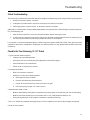
This section will provide the service technician asistance to diagnose a malfunctioning clutch using the following 3-step process:
1.
Identify the customer’s specific “complaint”.
2.
Investigate the “possible causes” that can be contributing to the customer’s complaint.
3.
Perform appropriate “corrective actions” to remedy the customer’s complaint.
Additionally, it is intended that a thorough reading/understanding of the previous section (Failure Analysis) and the following section (Troubleshooting) will:
1.
Allow the service technician to solve some complaint problems without removing the clutch.
2.
If clutch removal is necessary, these sections will give the technician the appropriate information for determining why
the clutch may have failed, thus preventing a possible reoccurrence of the complaint.
Checklist for Poor Releasing 15-1/2" Clutch
1. Typical customer release complaints:
•
Creeping with clutch pedal depressed.
•
Grinds going into first or reverse gear (given adequate time and vehicle stopped).
•
Clutch brake does not stop transmission.
•
Difficult to get out of gear (first & reverse).
2. Investigate the problem.
•
What is the customer’s complaint?
•
Questions to confirm clutch release complaint:
a.
Which gears are giving a problem?
b.
Does the clutch brake stop the transmission?
c.
How far off the clutch brake can you still pull in and out of gear?
d.
Does it grind going into gear or is it hard to pull in?
3. Measurements/checks to make:
•
Measure release bearing travel (take the free pedal out by pushing lightly on the pedal with your hand to load bearing).
•
Measure clutch brake squeeze (hint: use a business card or a .010” feeler) Response: Minimum 1/2”.
•
While pushing pedal down, check linkage for interference or premature bottoming.
4. Use a 1/4” diameter flat-nosed drift and lightly tap each of the four separator pins to ensure they are against the flywheel.
5. Does the clutch release?
31
Troubleshooting
It is important to note that the statements/photos of failed components represent quality Eaton Fuller Clutch parts which were
subjected to abuse and/or misapplication. Consequently, the failures pictured in no way represent defective Eaton Fuller Clutch
components.
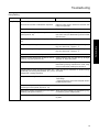
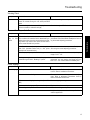
Troubleshooting
Pull Type Clutches - Poor Release
Complaint
Possible Causes
Poor Release
Intermediate plate sticking on drive lugs due to Drive pins must be 90° square to the flywheel surface
cocked drive pins (AS and EP 1402 only) (see Figures with .006 minimum clearance between drive pins and
18 - 19)
intermediate plate slots.
Pressure plate not fully retracting
Corrective Action
Check pressure plate return springs to see if bent,
stretched, or broken. These springs can be replaced
through the inspection opening. Transmission removal is not necessary.
Verify that the release bearing travel is 1/2”—9/16”.
Determine if the lever nose is out of the groove in the
release sleeve retainer. If it is, be sure to reinstall.
Excessive release bearing travel, causing lever to con- Adjust to 1/2”—9/16” release bearing travel.
tact pressure plate (in excess of 5/8”)
Incorrect pedal height
Set the pedal height so you can obtain:
—1/2” to 9/16” release bearing travel
—1/8” free travel at the release yoke and
—1/2” to 1” clutch brake squeeze
Consult the truck service manual or Eaton’s Installation Instructions.
No clutch brake squeeze
1/2”—1” required.
Damaged bushing in the release bearing sleeve as- Replace cover.
sembly
Cover assembly not properly seated into pilot of fly- Reseat into flywheel. Use crisscross pattern when
wheel
tightening mounting bolts.
The spacer ring & intermediate plate assembly (Solos If the clutch cover has already been bolted to the flyand SAS 1402 only) was bolted up backwards onto wheel, it is imperative that it be replaced with a new
the flywheel (see Figures 34 - 37)
intermediate plate assembly because permanent
damage may have occurred to the drive straps and
spacer ring. Also, thoroughly inspect the cover for
any damage and replace if damaged.
The intermediate and/or pressure plate is either Replace any damaged parts. This failure is caused by
cracked or broken (see Figures 13 - 14 and 25)
driver abuse or excessive heat as indicated by the
following:
—Holding vehicle on hill with the clutch
—Overload
—Starting off in the wrong gear
—Wrong cover assembly installed allowing clutch to
slip (misapplication)
—Intermediate plate hanging up, allowing clutch to
slip
32
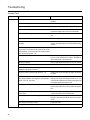
Troubleshooting
Poor Release
Complaint
Possible Causes
Poor Release Release sleeve bushing is contacting the transmis(Continued)
sion input shaft due to a side loading condition. This
condition can be the result of one or more of the following items:
—Cross shafts protruding through the release yoke
—Finger(s) of release yoke are bent
—Clutch cover is not mounted concentric and/ or not
properly seated into the flywheel pilot
—Misalignment between the transmission bell housing and engine housing
—Loose transmission mounting bolts
—Improper setup of linkage
—Check for protruding cross shafts.
—Install a new release yoke.
—When mounting clutch cover to the flywheel, always tighten the mounting bolts to their proper
torque using the crisscross pattern.
—Refer to Eaton’s Installation Instructions on the
proper techniques for checking misalignment.
—Tighten bolts to proper torque.
—Thoroughly examine the linkage to determine if it
can be contributing to a side loading condition.
Damage to driven discs can be caused by poor installation methods. Do not force transmission drive gear
into disc hubs. This will distort or bend driven disc
causing poor release. Also, do not allow transmission
to hang unsupported. Replace any distorted or
warped discs.
Disc(s) installed backwards (see Figures 49 & 50) or Install new discs. Also, investigate the clutch cover
front and rear discs were switched with each other
for any damage. Replace if damaged.
Spline worn on main drive gear of transmission.
(see Figure 77)
Replace drive gear and check driven disc hubs for excessive wear. If worn, replace disc. Check flywheel
housing alignment of engine and transmission. Make
sure driven discs slide freely on drive gear splines.
Flywheel pilot bearing fits either too tight or too loose Check pilot bearing for proper fit.
in the flywheel and/or end of input shaft
Damaged or dry (rough) pilot bearing (see Figure 76) Replace with new bearing.
Failure to use the anti-rattle springs packaged with all Always use new anti-rattle springs.
14” AS and EP Super Duty clutches (see Figures 20 22)
(3) Anti-rattle springs were installed backwards (see Install them so the rounded sections are pointing toFigures 23 - 24)
ward the flywheel/engine.
Failure to set the positive separator pins during clutch It is important to note that the procedure for setting
installation
the positive separator pins (model 1552, Solo & SAS
1402 clutches) can be performed while the transmission is installed. The steps are as follows:
1. Remove the transmission inspection hole cover.
2. Rotate the clutch cover until one of the holes (for
setting the pins) is at the 6 o’clock position.
3. Using the appropriate tool, lightly tap the separator
pin to verify that it is seated against the flywheel.
4. Repeat steps 2 and 3 for the remaining three separator pins.
5. Reinstall the transmission inspection hole cover
For additional information, refer to Eaton’s Installation Instructions.
33
Troubleshooting
Driven disc distorted or warped (see Figure 47)
Corrective Action
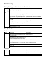
Troubleshooting
Poor Release
Complaint
Possible Causes
Corrective Action
Poor Release Bent/damaged positive separator pin(s) (see Figures 1. Be sure to use the proper tool when setting the
(Continued)
31 - 33)
pins.
2. Take great care when handling the intermediate
plate.
The release yoke bridge is contacting the cover as- It is highly recommended that the (6) six items listed
sembly at the full release position (clutch pedal to next to Figures 1 and 2 be thoroughly investigated befloor) (see Figures 1 - 2)
fore installing a new clutch.
Damaged or non-functioning clutch brake (see Fig- Install new clutch brake when installing a new clutch
ures 73 - 74)
and/or replace existing brake with 2 piece (Kwik-Konnect type).
Rust preventative, i.e. never seize, grease, etc. on Drive gear should be clean and dry before installing
transmission input drive gear (see Figures 43 - 45)
discs.
Incorrect use of clutch brake when shifting into 1st
gear. Sometimes when applying the clutch brake with
the vehicle on a grade, the transmission gears can become locked together due to the applied torque, making it difficult to shift into and out of gear.
Let up on the clutch pedal a few inches in order to disengage the clutch brake. Doing so will allow the input
shaft to roll-over slightly, eliminating the locking condition of the transmission gears and allow for effortless shifting.
Facing of driven disc assemblies are coated with oil or Replace the driven disc assemblies. Cleaning of old
grease (see Figures 41, 43 - 44)
discs is not recommended.
Foreign material on the internal workings of the clutch Remove foreign material. Ensure that the transmiscover (dirt, chaff, salt, etc.)
sion inspection hole cover is reinstalled to minimize
future problems.
34
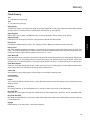
Troubleshooting
Noisy/Rattling
Complaint
Possible Cause
Corrective Action
Noisy/Rattling
Excessive flywheel runout
Consult Eaton’s Installation Instructions.
Corrosion of disc hubs to transmission input shaft
Clean the mating parts to ensure that the discs slide
freely over input shaft.
Engine idling too fast
Readjust engine to proper idling speed.
Clutch release bearing is dry or damaged
(see Figures 28 - 29)
Lubricate the bearing. If the noise persists, install a
new clutch cover (the release bearing will be included
with the cover).
Flywheel pilot bearing is dry or damaged (see Figure Replace flywheel pilot bearing.
76)
Refer to the section titled: “Failure - yoke bridge rubbing into clutch cover,” Figures 1 - 2.
Fingers of release yoke hitting clutch cover
Refer to the section titled: “Failure - yoke fingers rubbing into clutch cover,” Figures 4 - 5.
Failure to use the transmission inspection hole cover Re-install the cover.
Failure to use anti-rattle springs (AS and EP 1402 Su- Always install the new anti-rattle springs packaged
per-Duty only) (see Figures 20 - 22)
with each 14” Super-Duty clutch.
Worn sleeve bushing
Investigate for any side loading conditions on the release bearing housing. Determine the cause, being
sure to correct before installing the new clutch.
Linkage system is frozen, improperly lubricated, worn Clean, lubricate and reassemble or replace missing/
excessively, has missing parts (washers, etc.), or the worn parts.
linkage itself is rattling excessively
Idle gear rattle coming from the transmission
—Specify driven disc assemblies which feature FreeTravel design.
—Check the engine for the correct idle speed. Consult
the OEM engine manual.
Dampener spring cover of the driven disc assembly Install correct clutch assembly.
interfering with the flywheel (Figures 48 - 52)
Rivets of the rear disc are interfering with the retainer Adjust the clutch internally (via the adjusting ring),
assembly (see Figures 25 and 57)
not externally (via the linkage system).
Clutch is loose on flywheel (see Figures 8 - 10)
Install a new clutch assembly and eight new mounting bolts.
35
Troubleshooting
Bridge of the yoke hitting clutch cover
Troubleshooting
Vibrating Clutch
Complaint
Possible Cause
Vibrating Clutch Loose flywheel
Corrective Action
Retighten flywheel mounting bolts to the proper specifications.
Worn universal joints
Replace worn parts.
Improper phasing of driveshaft
Investigate for correct yoke phasing.
Driveshaft is not balanced
Balance and straighten driveshaft. Also, ensure that
no balance weights have come off the driveshaft.
Incorrect driveline angles
Shim drivetrain components to equalize u-joint angles.
Flywheel is not balanced
Balance the flywheel.
Pilot area of the clutch is not completely seated into Ensure that no dirt, burrs, etc. are preventing the covflywheel
er from completely seating into the flywheel mounting
surface.
Failure to tighten the clutch cover mounting bolts, us- Consult Eaton Clutch Service Manual.
ing a criss cross sequence, can cause an out-of-balance condition. Loose mounting bolts can also induce
this condition (Figures 8 - 10)
Damaged, loose, or worn out engine mounts
Replace any damaged/worn parts. Retighten all loose
bolts to proper specifications. Refer to the OEM engine manufacturer’s service manual.
Misfiring of engine
Refer to OEM engine manufacturer’s service manual.
Excessive flywheel runout
Refer to Eaton’s Installation Instructions.
Rivets of the rear disc are interfering with the retainer Adjust the clutch internally instead of externally.
assembly (see Figures 25 and 57)
Clutch is loose on flywheel (see Figures 8 - 10)
Install a new clutch assembly and eight new mounting bolts.
Insufficient amount of free travel. When the clutch After first adjusting the clutch for l/2”-9/16”release
was initially installed, the linkage was not adjusted to bearing travel, adjust the linkage to obtain an 1/8” free
obtain a full 1/8” free travel
travel (distance between the release yoke fingers and
the release bearing wear pads) travel.
Misapplication of clutch, causing premature wear
If a service clutch, determine whether the clutch is
properly specified for the vehicle’s particular application.
Starting out in too high a gear may lead to premature Start the vehicle in the proper gear. Refer to item 1 of
clutch wear
“Factors That Effect Clutch Performance”.
36
Worn cross shafts and/or linkage system
Investigate entire linkage system to determine if it is
binding or operating sporadically and/or worn excessively.
Clutch discs wore down to rivets
Install new clutch.
Riding of clutch pedal, causing premature wear
Refrain from using the clutch pedal as a foot rest.
Troubleshooting
Vibrating Clutch
Complaint
Possible Cause
Corrective Action
Holding the vehicle on an incline by using the slipping Refrain from using the clutch pedal as a brake.
clutch as a brake. Doing this can cause premature
wear.
Sporadic changes in the amount of free play/free trav- Consult the engine OEM Service Manual.
el due to excessive crankshaft end play
Too much Free Play on Solo Clutch
Complaint
Possible Cause
Corrective Action
Solo Clutch has over adjusted (release bearing is less Reset the wear tab to the new position. Readjust the
than .500” {standard stroke Solo} or .430” {short Solo using the normal adjusting procedures.
stroke} from the transmission)
Failure to properly set-up the clutch linkage
Reset the linkage to obtain a free travel (at the yoke)
range of 1/16” -1/8”.
Nothing is wrong. It is normal for the free play to in- None is required, but if the additional free play is obcrease during the Solo’s “Breaking in” period.
jectionable, you may readjust the linkage until you
have 1/16” -1/8” of free travel at the release yoke.
Clutch Slippage
Complaint
Possible Cause
Corrective Action
Clutch Slippage
No free pedal
Readjust clutch. Refer to adjustment instructions
found in Eaton’s Installation Instructions.
Release mechanism binding
Free up mechanism and linkage, check clutch adjustment. Refer to adjustment instructions found in
Eaton’s Installation Instructions.
Failure to remove shipping/resetting bolts (Solo HD & Remove shipping/resetting bolts.
MD)
Grease or oil on facings (see Figures 41, 43 - 44)
Replace driven disc assembly.
Driver riding clutch pedal
Refrain from riding clutch pedal.
Overloaded clutch
Verify that the proper clutch has been specified for the
vehicle’s application.
37
Troubleshooting
Too much Free Failure to install a clutch brake when one is required. Reset the wear tab to the new position. Install a 2Play on Solo This condition will cause the Solo’s release bearing to piece Eaton Fuller Clutch Brake. Readjust the Solo usClutch
adjust closer than normal to the transmission’s bear- ing the normal adjusting procedures.
ing retainer cap and will also cause the wear tab to
move toward the half worn position.
Troubleshooting
Chattering, Erratic Engagement, Clutch Grabs, truck is difficult to launch
Complaint
Possible Cause
Chaffering, Er- Input shaft spline wear (see Figure 77)
ratic Engagement,
Clutch
Grabs
Corrective Action
Replace input shaft.
Clutch is worn out - the driven disc assembly(s) have Replace all worn components.
worn down to the facing rivets (see Figure 70)
The linkage system is not operating freely, it is bind- Replace all worn parts, being sure to lubricate according and/or worn excessively (see fig. 75)
ing to the OEM Service Manual.
Grease/oil on the disc(s) facing material (see Figure Replace disc(s).
41, 43 - 44)
Loose engine mounts
Retighten to OEM specs.
The fingers of the release yoke and/or the wear pads Replace all worn parts.
on the release bearing are worn excessively (see Figures 29 and 79)
The electronic engine is not programmed properly re- Consult with OEM engine manufacturer.
garding clutch engagement torque.
Push - Type Clutches
Poor Release
Complaint
Possible Cause
Corrective Action
Poor Release
Insufficient amount of clutch pedal height may pre- Consult the OEM Service Manual and/or Eaton’s Invent the throw out bearing from traveling far enough stallation Instructions.
to disengage the clutch
Incorrect throw out bearing was installed. A throw out Install the correct throw out bearing.
bearing assembly that is too short cannot travel far
enough to enable full disengagement of the clutch
Excessive free pedal in the cab - the clutch cannot ful- Consult the OEM Service Manual.
ly disengage
Throw out bearing is hanging up on the quill (stem) Consult the OEM Service Manual.
of transmission
Missing and/or improper torquing of clutch cover Consult Eaton’s Installation Instructions.
mounting bolts
Incorrect driven assembly installed - it is too thick
Install the correct disc.
Complaint
Possible Cause
Corrective Action
Noise/Rattling
Throw out bearing is worn/seized
Replace the throw out bearing. If reusing the clutch,
ensure that the release levers are not damaged (see
Figure 38).
Incorrect driven disc has been installed
Install correct driven disc assembly.
Noisy/Rattling
38
Glossary
Clutch Glossary
1401
14” single plate clutch (pull-type).
1402
14” two plate clutch (pull-type).
Adjusting Ring
Threaded lever support ring inside clutch. Needs to be rotated toward FW to keep proper angle relationship between pressure
springs and levers. Turned by mechanic via Kwik-Adjust (SAS and EPP), or lock strap (AS).
Angle-Ring (A/R)
Medium-Duty, push to release, uses Belleville spring, no internal adjustment, 310mm, 330mm (Ford), 350mm.
Angle Spring (AS)
Predecessor to EP. No longer in production. Large population in Reman and rebuilt markets.
Bearing Travel
With clutch engaged, gap between rear bearing cover and front of clutch brake (or transmission bearing cap if not using clutch
brake). This is how far the bearing moves when the pedal is depressed. Adequate bearing travel is required to release clutch completely, and for Solo to adjust Industry standard: .530 ± .030” (1/2” - 9/16”).
Clutch Brake (CB)
Brake device that rides on transmission input shaft of unsynchronized transmissions behind clutch release bearing. “Sandwiched”
between back cover of clutch bearing and front of transmission bearing cap. Should be used to stop excess disc rotation when
shifting into first or reverse. Single Piece - Torque limiting (OE standard), Two Piece - not torque limiting (service replacement).
Clutch Brake Squeeze
Distance of clutch pedal movement from floor of cab to point at which a 0.010” feeler gage is no longer clamped between back of
clutch bearing and front of transmission bearing cap. Target usually around 1”.
Coaxial (CO)
Spring inside of a spring. Many dampers use this design to achieve higher bottoming torque.
Cover Assembly
see Pressure Plate.
Damper
(Disc, Driven Disc, DDA, Clutch Plate) Portion of clutch affixed to transmission input shaft. Supports friction facings and torsional
damping springs.
Drive Pins
(Drive Dogs) Used with 14” pot style flywheel and 14” cast clutch. Used to carry torque of intermediate plate.
Easy-Pedal (EP)
Heavy duty 15.5” cast 2-plate clutch that uses 3 assist springs to reduce release loads. Launched in ’90 now superseded to EPP.
Easy-Pedal Plus (EPP)
Easy-Pedal with added features: 2-piece retainer, Super Seal on adjustment threads, improved Kwik-Adjust, positive pin separator
in intermediate plate.
Engaged
Release bearing is in its rest position - clutch discs clamped up.
39
Glossary
Bearing Load
Load applied to release bearing to move it .500” releasing the clutch. Bearing load relates to load at clutch pedal.
Glossary
Free Pedal (FP)
(Free Play, Toe Play) Amount the clutch pedal moves inside the cab before the release yoke contacts the wear pads on
the release bearing. Usually 1/8” of free travel gives 1.5” to 2.5” (depends on OEM & Model).
Front Intermediate Plate
Towards the engine.
Intermediate Plate
(Center Plate, Floater Plate) Cast iron plate between front and rear driven discs. 14” MD driven by straps affixed to aluminum spacer ring, 14” cast driven by (6) drive pins mounted in pot flywheel, 15.5” cast driven by (4) integral
lugs fitting into cover assembly slots.
Kwik-Ajust
Adjustment mechanism used to adjust non-Solo pull clutches. Small gear when depressed engages adjusting ring allowing it to
be turned to maintain proper adjustment.
O.E.M.
Original Equipment - Usually refers to the manufacturer of the vehicle.
Positive Separator Pin
Steel pegs positioned around the outer edge of the Pin intermediate plate to ensure a constant gap on both sides of the plate as
the clutch is released.
Pot Flywheel (Pot FW)
Flywheel used only with 14” cast clutches - shaped like a cast iron pot. Front disc, intermediate plate, and rear disc contained
inside flywheel
Pressure Plate (PP)
(Clutch Cover, Flywheel Ring, Flywheel Bracket): 1. The actual cast iron plate that squeezes driven disc(s). 2. The assembly that
contains the pressure plate, springs, release bearing.
Pull
When clutch pedal in cab is depressed, release bearing (throw-out bearing) is pulled away from the engine to release the clutch.
Push
When clutch pedal in cab is depressed, throw-out bearing (release bearing) is pushed toward the engine to release the clutch.
Rear
Towards the transmission.
Solo™
Eaton Fuller’s adjustment-free clutch.
Stamped Angle Spring (SAS)
14” Medium-Duty pull release clutch. Name comes from stamped steel cover. Both single plate and two plate versions. Usually
refers to adjustable type (Kwik-adjust).
Super-Duty
14” cast EPP with thicker than original intermediate plate to achieve 1400 Lb-ft. Also requires anti-rattle springs. Used with pot
flywhee.
Throw-out Bearing
Also known as release bearing in reference to pull style clutches. Refers to bearing housing and bearing which is pulled to release
the clutch.
40
Copyright Eaton and Dana Corporation,
2002. EATON AND DANA CORPORATION
hereby grants its customers, vendors, or
distributors permission to freely copy,
reproduce and/or distribute this document
in printed format. THIS INFORMATION IS
NOT INTENDED FOR SALE OR RESALE, AND THIS NOTICE MUST REMAIN
ON ALL COPIES.
The Roadranger® System is an unbeatable combination of the best
products from Eaton and Dana – partnering to provide you the most
advanced, most trouble-free drivetrain in the industry. And it’s backed by
the Roadrangers – the most experienced, most expert, most accessible
drivetrain consultants in the business.
For spec’ing or service assistance, call 1-800-826-HELP (4357) 24 hours
a day, 7 days a week, (Mexico: 001-800-826-HELP (4357)) for more time
on the road. Or visit our web site at www.roadranger.com.
CLTS-1271
6/03 PDF
Printed in USA