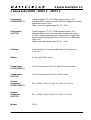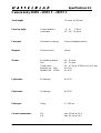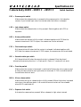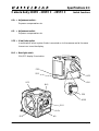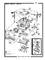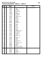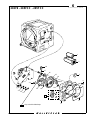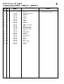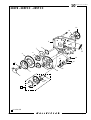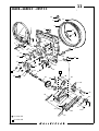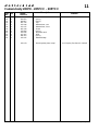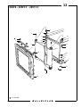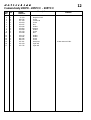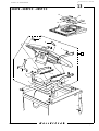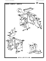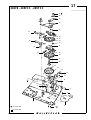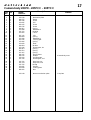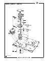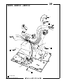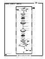
1
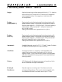
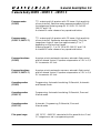
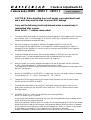
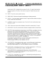
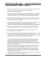
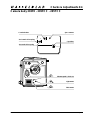
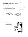
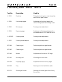
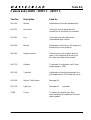
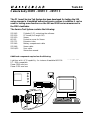
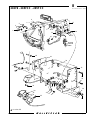
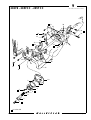
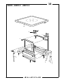
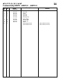
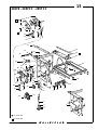
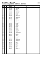
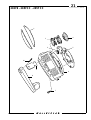
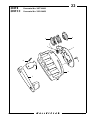
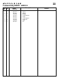
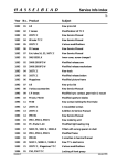
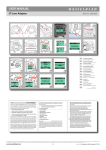
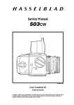
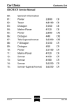
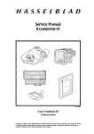
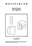
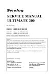
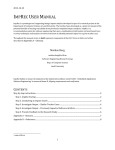
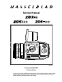
203FOMSL.EPS
203FE, omslag
Service Manual
SVART
960130
May 1997
Victor Hasselblad AB
Göteborg Sweden
COPYRIGHT © 1996
Copyright © 1997 by Victor Hasselblad AB. All rights reserved. No parts of this material may be reproduced, stored
in retrieval system or transmitted, in any form or by any means, electronic, mechanical, photocopy, recording, or
ANDERS ENGSTRÖM
otherwise, without the prior written permission of the Company.
ANDERS ENGSTRÖM, ILLUSTRATÖR
Östra vägen 46
430 91 HÖNÖ
TEL/FAX 031- 96 84 64
Contents list
Camera body 203FE - 205FCC - 205TCC
1.
General description
2.
Specifications
3.
Checks & Adjustments
4.
Tools & ServiceTest System
5.
Exploded view: Shell
6.
Exploded view: Control panel, mechanics
7.
Exploded view: Control panel, electronics
8.
Exploded view: Display flex and main circuit board
9.
Exploded view: Contact flex and transport mechanism plate
10.
Exploded view: Transport mechanism plate
11.
Exploded view: Front bayonet plate
12.
Exploded view: Curtains and rear plate
13.
Exploded view: Mirror assembly
14.
Exploded view: Display prism and fucusing screen
15.
Exploded view: Chassis
16.
Exploded view: Reflection protectors
17.
Exploded view: Bottom mechanism plate, mechanics
18.
Exploded view: Bottom mechanism plate, brakes
19.
Exploded view: Bottom mechanism plate, electronics
20.
Exploded view: Spring housing
21.
Exploded view: Winding crank
22.
Exploded view: Winding crank - modified from May 1997
Revision 0
May 1997
Related Service Infos
203FE - 205FCC - 205TCC
1.
03/92
New Service Manual
05/92
Service Manual 205TCC System Components
04/93
Some more hand tools are now available
05/93
The release button and buffer have recently been modified - 205TCC
12/93
Just for your information
13/93
Hasselblad 205TCC
21/93
Camera body 205TCC and Magazine TCC
09/94
The control panel has recently been redesigned - 205TCC
10/94
New camera body - 203FE
03/95
New tool - Support 904020
05/95
New tripod foot - 203FE
14/95
Mirror and focusing screen adjustment 200 series cameras
19/95
New camera body - 205FCC
24/95
Incorrect spare part number - 205TCC
28/95
New tool - Adapter 904759
01/96
Contact flex modified - 203FE
03/96
Driving arm failed to latch - 203FE and 205FCC
12/96
Tripod foot adapter/kits
04/97
Light seal foil modified - 200 series cameras
13/98
New Service Manual - 203FE, 205FCC and 205TCC
08/99
New control panel - 205TCC
13/99
Modified parts - 200 series cameras
01/00
New CD-ROM - Version 1.2
Revision 3
January 2001
Related Service Infos
203FE - 205FCC - 205TCC
14/00
Discontinued parts - 200 series cameras
01/01
Modified magazine hook - 203FE and 205FCC
04/01
New CD-ROM - Version 2.0
Revision 0
2.
January 2001
General description 1:1
Camera body 203FE - 205FCC - 205TCC
Design:
Medium format single reflex camera with built-in TTL selective
meter electronically connected to FE lenses and E magazines.
Interchangeable lenses, film magazines, viewfinders and
focusing screens.
Shutter:
(203FE/205FCC)
Electronically controlled mechanical focal plane shutter with
release solenoid system. Horizontally running textile curtains.
Shutter speed range 90 s - 1/2000 s and B. In manual mode up
to 34 minutes. Fully mechanical C setting for lenses with
built-in leaf shutters.
Flash synchronization at all speeds from B to 1/90 s.
Shutter:
(205TCC)
Electronically controlled mechanical focal plane shutter with
release solenoid system. Horizontally running textile curtains.
Shutter speed range 16 s - 1/2000 s and B. Fully mechanical C
setting for lenses with built-in leaf shutters.
Flash synchronization at all speeds from B to 1/90 s.
Lens mount:
Hasselblad bayonet mount for FE, F, CF and C lenses. Contacts
for data-bus communication with the FE lenses.
Viewfinder:
Focusing hood with 4 x magnifier, interchangeable with
magnifying hood and prism viewfinders with or without
exposure meter. Acute-Matte focusing screen interchangeable
with other Hasselblad focusing screens. Illuminated flash and
warning symbols.
Display:
LCD display with all relevant exposure and operational data.
Switch-controlled low light illumination.
Winding &
film advance:
Manual single turn winding crank. Simultaneous shutter
cocking and film advance. The crank is interchangeable with
the Hasselblad Winder for a frame rate of up to 1.3 fps.
Revision 0
May 1997
General description 1:2
Camera body 203FE - 205FCC - 205TCC
Exposure meter:
(203FE)
TTL metering at full aperture with FE lenses. High sensitivity
silicon photocell. Selective meter area approximately 20% of
the image area. Metering range EV 0.5 to EV 21.5 at ISO
100/21° and f 2.8.
Activated 16 s after release of any operational button.
Exposure meter:
(205FCC/205TCC)
TTL metering at full aperture with FE lenses. High sensitivity
silicon photocell. Spotmeter area approximately 1% of the
image area. Angle of view from approximately 1° to 7°
depending on the lens focal length.
Metering range EV -1 to EV 20 at ISO 100/21° and f 2.8.
Activated 16 s after release of any operational button.
Exposure functions:
(203FE)
Aperture priority automatic exposure, automatic flash control
and full manual control. Exposure compensation ± 5 EV in 1/3
EV increments. AE-lock.
Exposure functions:
(205FCC/205TCC)
Aperture priority automatic exposure, automatic flash control
and full manual control. Exposure compensation ± 5 EV in 1/4
EV increments. AE-lock.
Operating modes:
(203FE)
Programming, Automatic bracketing, Differential, Automatic
and Manual mode.
Operating modes:
(205FCC)
Programming, Automatic bracketing, Differential, Zone and
Manual mode.
Operating modes:
(205TCC)
Automatic, Programming, Differential, Zone and
Manual mode.
Film speed range:
ISO 12/12° - 6400/39°, selected with film speed dial on E and
CC magazines or set in programming mode.
Revision 0
May 1997
General description 1:3
Camera body 203FE - 205FCC - 205TCC
Flash control:
(203FE/205FCC)
Center weighted TTL/OTF flash exposure meter. Full
dedicated flash control with inhibited flash triggering at shutter
speeds faster than 1/90 s.
Flash control film speed range ISO 25 - 1000.
Flash control:
(205TCC)
Center weighted TTL/OTF flash exposure meter. Full
dedicated flash control with automatic shutter speed reset
to 1/90 s at faster speed settings. Inhibited flash triggering at
shutter speeds settings faster than 1/90 s with non-dedicated
flash units.
Flash control film speed range ISO 25 - 1000.
Self timer:
Default delay 10 s. Programmable delay in 12 steps from
2 s to 60 s.
Battery:
6 volt, type PX28 Lithium.
Tripod mount:
(203FE/205FCC)
Quick coupling plate with 1/4" and 3/8" socket thread.
Tripod mount:
(205TCC)
Quick coupling plate with 1/4" socket thread.
External
dimensions:
(203FE/205FCC)
91L x 118W x 110H (3 9/16 x 4 21/32 x 4 1/32 in).
External
dimensions:
(205TCC)
91L x 118W x 108H (3 9/16 x 4 21/32 x 4 1/4 in).
Weight:
745 g.
Revision 0
May 1997
Specifications 2:1
Camera body 203FE - 205FCC - 205TCC
71.4 mm ± 0.03 mm
Focal length:
Front key angle:
Cocked position
Overtravel
8° - 9°
3 Ncm
12° - 14° 14 Ncm
Front gear:
Pre-tension of spring
3 turns (released position)
Magnets:
Minimum hold
2 Ncm
Shutter:
Accelerating stretch
Slot
Travel times
Speeds 1 sec - 1/60
Speeds 1/90 - 1/2000
6.5 - 8.1 mm
0.2 - 1.0 mm
9.5 - 9.7 ms at 1/2000 s (0 ± 0.07 ms)
± 0.1 EV
± 0.3 EV
Light meter:
All settings
± 0.3 EV
Flash meter:
All settings
± 0.3 EV
Flash sync:
Delay
0 - 0.20 ms
Current consumption:
On
Off
max 10 mA at 5.6 V
max 20 uA at 5.6 V
Revision 0
May 1997
Specifications 2:2
Camera body 203FE - 205FCC - 205TCC
Switch functions
PPS = Pressure point switch
Makes when the release button is pressed to the pressure point. Activates the
camera. A pre-locked light value is unlocked when the button is released.
LRS = Late release switch
Makes when the release button is fully pressed. Starts together with PPS an
exposure.
HPS = Home position switch
Makes when the camera is fully cocked. Indicates together with FSS that the
camera is tensioned. If HPS is open, the camera can not be activated.
FSS = First curtain sync switch
Will be switched off when the first curtain is released. Indicates together with
HPS that the camera is tensioned. If FSS is open, the camera can not be activated.
SSS = Second curtain sync switch
Will be switched off when the second curtain is released. Must be closed,
otherwise the warning function: Lo Flash and Hi Flash in C-mode will not work.
FKS = Front key switch
Makes when the camera is tensioned. Is switched off when the mirror goes up and
at that time also prevents new light values to be stored. If FKS is not switched off
the selftimer does not work.
MRS = Mirror release switch
Makes when the mirror release button is fully pressed. When the button is pressed
once more, the selftimer starts. In B-mode the second curtain will be released
when MRS is switched off.
ELS = Exposure lock switch
Activates the camera when pressed. When released, a light value is stored.
Revision 0
May 1997
Specifications 2:3
Camera body 203FE - 205FCC - 205TCC
Switch functions
AS+ = Adjustment switch +
Exposure compensation etc.
AS- = Adjustment switch Exposure compensation etc.
VFS = View finder switch
Is switched off when a prism finder is mounted on to the camera and at the same
time mirror turns the display.
203SWTC
BLS = Back light switch
ON/OFF display illumination.
FSS
SSS
TC1.EPS
HPS
LRS
VFS
960201
BLS
PPS
COPYRIGHT © 1996 ANDERS
ANDERS ENGSTRÖM, ILLUST
Östra vägen 46
430 91 HÖNÖ
TEL/FAX
MRS
ELS
AS+
FKS
Revision 0
1996 ANDERS ENGSTRÖM
TRÖM, ILLUSTRATÖR
TEL/FAX 031-96 84 64
AS-
May 1997
Checks & Adjustments 3:1
Camera body 203FE - 205FCC - 205TCC
Link to: VHABSTS
CAUTION! When handling the circuit boards a grounded bench mat
and a wrist strap must be used to prevent ESD damage.
Carry out the following checks/adjustments when a camera body is
reassembled after a repair.
Note! Point 1 - 7 without camera shell.
1.
The camera body focal length is checked by using the gauge V-2229 together with the ruler
and indicator clock. The focal length is 71.40 mm ± 0.03 mm. Adjustment slots on the
chassis and the bottom mechanism plate.
2.*
Secure the camera in the gauge V-2229 by the adapter 904759. Check the 45º
mirror angle with the sighting tube. The image seen, should be symmetrical. Adjust, if
necessary, the four supports in the mirror box by using the tools 901046 (front supports)
and 904018 (rear supports).
3.*
Check the flatness of the screen. Use the screen adapter V-4705 and the ruler with the
indicator clock. The same measurement should be obtained at all four corners.
Adjust, if necessary, by the four screws (Pos No. 28, page 15).
4.*
After the screen is correctly levelled the height must also be checked. Use the collimator
V-4151, the screen adapter V-4705 and the microscope V-2236.
The image seen in the microscope should be the red line central between the two green lines.
Recheck the flatness.
5.
Use the tool 902658 or V-2075/2151 for checking of the front key angle. Adjust if necessary.
Cocked position 8° - 9° 3 Ncm. Overtravel 12° - 14° 14 Ncm.
6.
Temporarily fit the control panel to the camera body and secure it with a piece of tape.
Use the nut driver 903755 or 903474.
7.
Connect the camera body to the Service Test System and go through all checks in the
given order according to the 203/205 menu. Note! pos. 7:1 to 7:7 without sensor head
and light source.
7:1
CAMERA STATUS. Make sure all switches are working properly.
Note! The speed ring in C-position.
If the contact flex has been removed at any time, the timing between the pre-release switch
(PRS) and the mirror must be checked.
Mount the test shell, 905002, with four screws. Fit the exposure gauge V-2354 in the release
button and slowly rotate the micrometer clockwise and observe when the mirror is released.
At the same time (not before) the PRS should change from "open" to "closed" on the screen.
A slight delay is acceptable. This corresponds to 1.5 divisions on the scale.
Adjust, if necessary, by altering the position of the rear section of the contact flex
Revision 3
February 2000
Checks & Adjustments 3:2
Camera body 203FE - 205FCC - 205TCC
containing the PRS. Untighten the two screws (Pos. No. 12, page 9) and carefully
change the position of the flex in the direction required. Tighten the screws and
recheck.
7:2 PANEL. Check the control panel functions.
7:3 SPEED RING. Make sure all speed ring settings are indicating correctly.
7:4 DISPLAY. Check the display indications. Note! To get the flash indicator to light up,
the sync cable must be connected.
7:5 CURRENT. Check the consumption (max. 10 mA at 5.6 volt) and the drain (max.
20 uA at 5.6 volt).
7:6 LENS. Check the communication between a lens and the camera body. (F-stops)
7:7 MAGAZINE. Check the communication between a magazine and the camera body.
7:8 SHUTTER. Start by adjusting the travel times. Use 1/2000 sec. and adjust the spring
housing until both curtains have a speed between 9.5 - 9.7 ms. (0 ± 0.07 ms).
At this point, also make a final adjustment of the braking mechanism if necessary.
The brake is checked as follows: Release the camera. Rotate the 2nd shutter gear
(Pos No. 25, page 17) and count the number of times the catch (Pos No. 4, page 18)
and the brake plate (Pos No. 3, page 18) engage. (Min. 4 times). For an adjustment
use the nut driver 903755 or 903474. (See page 3:4).
Check/adjust the speed 1/2000 sec. Use the "shutter speed" potentiometer for
an adjustment. (See page 3:4). Max. deviation ± 0.3 EV.
Check the speed 1/1000 sec. Max. deviation ± 0.3 EV.
7:9 LIGHT METER. Check/adjust the light meter. Use the "light meter" potentiometer
for an adjustment. (See page 3:4). Max deviation ± 0.3 EV. Do not use any
other light output except EV 15, since the camera is not built in to the shell.
7:10 FLASH SYNC. Check/adjust the flash sync. The delay is adjusted to 0 - 0.20 ms by
altering the position of the first sync contact. (See page 3:4).
7:11 FLASH METERING. Check/adjust the flash meter. Use the "flash meter"
potentiometer for an adjustment. (See page 3:4). Max. deviation ± 0.3 EV. Use the
setting ISO 100 and light output EV 15.
7:12 C-POSITION. Check/adjust the C-position. It is adjusted by extending/shortening
the release arm 103389. (See page 3:4).
Revision 1
June 1998
Checks & Adjustments 3:3
Camera body 203FE - 205FCC - 205TCC
8.
Remove the control panel. Make sure the four centering screws (Pos. No. 16 and 19,
page 11) are screwed in and put the camera body in to the shell.
Do not forget the pre-release button.
9.
After aligning the rear plate/shell tighten the two rear screws (Pos No. 32, page 5)
and adjust, if necessary, the horizontal relationship between the speed ring and the
shell by the screws (Pos No. 16, page 11) which are accessible through the shell.
10. Adjust the vertical relationship between the speed ring and the shell by the screws
(Pos No. 19, page 11) which are accessible through the shell and then tighten the
two front screws (Pos No. 34, page 5).
11. Check the upper edge alignment of rear plate and shell. Adjust, if necessary, by the
two screws (Pos No. 31, page 9) which are accessible through the shell .
Note! The rear edge of the shell must not protrude over the rear plate at any point.
12. Remount the control panel, the winding crank mechanism, the tripod foot, the
speed ring grip and the inner cover. (The inner cover by using the tool 901061).
13.* When the camera body is fully reassembled, recheck the focal length, the 45°
mirror angle and the screen position.
14. Connect the camera body to the Service Test System once again and go through all
checks once more. Minor adjustments are sometimes necessary to make.
At this stage, it is also possible to use different light outputs when checking the light
and flash meter since the camera body is mounted in to the shell.
* The 200 series cameras are built slightly different from the 500 series cameras
concerning the focusing screen adjustment. Due to the use of high precision test
equipment at the assembly line, deviations from perfect 45º mirror angle is
compensated for when adjusting the focusing screen position. Doing so we assure
minimum focusing differences over the full image format between the images on the
focusing screen and on the film.
The result of the factory screen adjustment is, that the screen position may not be
totally horizontal when tested in the gauge V-2229. This is still quite in order.
When servicing the 200 series cameras we recommend not to change the mirror
angle, provided it is in tolerance when checked with the sighting tube in gauge
V-2229. Deviations from perfect 45º angle has already been accompanied by nonhorizontal focusing screen position.
However, if the mirror angle is out of tolerance, adjustment has to be made using the
current procedures. (Service Info No. 14/1995)
Revision 1
June 1998
Checks & Adjustments 3:4
Camera body 203FE - 205FCC - 205TCC
203FADJM.EPS
203FE, adjustments
960130
Sync contacts
Curtain brakes
–
2nd curtain drive spring
1st curtain drive spring
–
+
+
–
+
C-position
+
–
+
–
+
–
Shutter speed 1/2000 sec
Light meter
Flash meter
COPYRIGHT © 1996 ANDERS ENGSTRÖM
ANDERS ENGSTRÖM, ILLUSTRATÖR
Östra vägen 46
430 91 HÖNÖ
TEL/FAX 031-96 84 64
Revision 0
May 1997
Checks & Adjustments 3:5
Camera body 203FE - 205FCC - 205TCC
Magnet hold capability
250
250
1
200
1
1
50
200 GRAM
50
1
The magnet hold capability can be checked according to the diagram below. A suitable
scale, like the ZZ88, should be used. When measuring, it must indicate minimum 2 NCM
(200 gram) before each latching lever is released.
If indicating less then 2 NCM, the magnets should be cleaned and then rechecked. If still
less then 2 NCM after cleaning the Bottom mechanism plate, compl. (Part No. 105028)
must be changed. Magnets and latching levers are not available as spare parts due to
sensitive calibration procedures.
VHAB Tool No. = ZZ88, Scale
The magnets can be released from the
main circuit board when troubleshooting.
Use an external DC power supply and
apply 5 volt to the test points indicated.
Do not forget the grounding.
Magnet 2
Revision 0
Magnet 1
May 1997
Tools 4:1
Camera body 203FE - 205FCC - 205TCC
Tool No.
Description
Used for
V-2211
Pin driver
Fitting the locating pin in the front plate
and the front gear bracket
V-2229
Focal length gauge
Adjustment of the focal length, the
mirror 45ºangle and the focusing screen
V-2236
Microscope
Focusing screen adjustment
V-2354
Exposure gauge
Adjustment of the timing between the
pre-release switch (PRS) and the mirror
V-4151/52
Focusing tester
Focusing screen adjustment
V-4705
Focusing screen adapter
Focusing screen adjustment
901 044
Centering pin
Positioning the front gear bracket
901 045
Centering pin
Positioning the front gear bracket
901 046
Bender
Adjustment of the mirror 45º angle
901 061
Mounting tool
Mounting the inner cover
902 658
Key angle gauge
Adjustment of the front key angle
903 282
Key
Securing a nut on the bottom plate
903 570
Shutter gear holder
Securing the shutter gears when fitting
the curtains
Revision 0
April 1998
Tools 4:2
Camera body 203FE - 205FCC - 205TCC
Tool No.
Description
Used for
903 630
Bender
Adjustment of the late release switch
903 755
Nut driver
Fitting the control panel and the
contact flex to the main circuit board
903 940
Key
Cocking the curtains before the
intermediate gear is fitted
904 018
Bender
Adjustment of the mirror 45º angle and
the auxiliary mirror position
904 020
Supporting tool
Protecting the control panel and the
main circuit board when working on
the right hand side of the camera
904 759
Adapter
To be used in combination with focal
length gauge V-2229
905 002
Test shell
Adjustment of the timing between the
pre-release switch (PRS) and the mirror
970 600
Service Test System
See page 4:3
905 138
Light box
See page 4:3
ZZ89
Driver
To tighten the special type allen
screw holding the chassis and the front
plate together
Revision 0
(optional)
April 1998
Tools 4:3
Camera body 203FE - 205FCC - 205TCC
The PC based Service Test System has been developed for testing the 200
series cameras in Hasselblad authorized service centres. In addition it can be
used for testing some functions on the 500 and 2000 series cameras and in
the PME viewfinder.
The Service Test System contains the following:
970 663
970 630
970 610
663 83
970 711
970 649
970 648
55034/23
Diskette (3.5") containing the software
PC-board (full length ISA)
Sensor
Protective cover for Sensor
Extension tube
Battery compartment cable
Sensor cable
Sync cable
Instruction manual
Additional components required are the following:
Light box with LV15 capability - for instance Hasselblad 905 138
PC - IBM compatible
Planar FE80 mm lens
Planar CF80 mm lens
Revision 0
VHABSTS.EPS
960130
April 1998
COPYRIGHT © 1996 ANDERS ENGSTRÖM
ANDERS ENGSTRÖM, ILLUSTRATÖR
Östra vägen 46
430 91 HÖNÖ
TEL/FAX 031-96 84 64
5
203FE - 205FCC - 205TCC
BOD20301.EPS
960130
48
5
2
3
1
10
6
4
47
7
8
11
9
48
46
12
13
13
45
19
14
18
44
15
16
43
28
29
20
27
30
42
17
21
39
25
40
26
24
38
205TCC
36
23
22
41
54
37
35
31
52
34
53
49
33
50
51
32
= Loctite 243
= Loctite 480
49
COPYRIGHT © 1996 ANDERS ENGSTRÖM
=
Loctite
638ILLUSTRATÖR
ANDERS
ENGSTRÖM,
Östra vägen 46
430 91 HÖNÖ
Revision 0
TEL/FAX 031-96 84 64
May 1997
5
Camera body 203FE - 205FCC - 205TCC
Pos Pcs
No.
Spare
Part No.
Description
1
2
3
4
5
6
7
8
9
10
1
2
2
2
1
1
2
1
1
1
105 025
12 978
815 604
809 120
13 907
13 906
835 001
105 475
13 466
13 190 -1
Shell, complete (chrome)
Plate
Spring
Steel ball
Holder, left
Holder, right
Pin
Leather
Strap button
Name plate
11
12
13
14
15
1
1
2
1
1
105 511
105 365
103 536
105 498
103 510
Leather
Display window
Index
Bushing
Leather
16
17
18
19
20
1
1
1
1
6
103 509
105 357
103 413
105 935
829 304
Leather
Bushing
Spacer
Strap button
Screw
21
22
23
24
25
1
1
1
1
1
105 509
105 432
107 390
105 874
105 862
Leather
Plate
Grip
Tape
Leather
26
27
28
29
30
2
1
1
1
1
831 502
103 387
103 388
22 514
40 387
Rivet
Bayonet
Spring
Reflection protector
Support plate
31
32
33
34
35
1
8
1
2
1
103 419
829 760
30 763
820 781
30 762
Pre-release
Screw
Tripod foot
Screw
Support, right
36
37
38
39
40
1
1
1
2
1
105 872
30 760
105 870
810 620
103 424
Tape
Support. left
Tape
Spacer
Spring
41
42
43
44
45
46
47
48
48
1
1
1
1
1
1
1
2
2
105 437
105 953
13 139
103 507
103 508
105 876
105 956
107 453
105 958
Release button
Buffer
Lens release button
Leather
Leather
Tape
Grip
Name plate 203FE
Name plate 205FCC
48
49
50
51
52
53
54
2
8
1
2
2
1
1
105 547
829 845
103 349
820 781
829 760
103 846
105 514
Name plate 205TCC
Screw
Slide
Screw
Screw
Tripod socket
Spacer
Revision 0
Remark
Part No. 105026 (black)
205TCC
"
"
"
"
"
"
May 1997
6
203FE - 205FCC - 205TCC
BOD20302.EPS
960130
1
2
18
17
16
3
15
25
14
4
13
21
5
20
24
23
12
19
7
6
10
22
4
11
8
9
= 3 pcs double-sided tape
COPYRIGHT © 1996 ANDERS ENGSTRÖM
ANDERS ENGSTRÖM, ILLUSTRATÖR
Östra vägen 46
430 91 HÖNÖ
TEL/FAX 031-96 84 64
Revision 0
May 1997
6
Camera body 203FE - 205FCC - 205TCC
Pos Pcs
No.
Spare
Part No.
Description
1
2
3
4
5
1
1
1
3
1
103 043
22 470
820 645
105 513
Battery
Battery compartment
Socket cap
Screw
Leather
6
7
8
9
10
1
2
1
1
2
103 536
829 335
105 512
105 304
105 536
Index
Screw
Leather
Cover
Indicator
11
12
13
1
1
1
1
1
105 127
105 522
107 456
105 914
105 955
Adjustment button
Ring
Mode sign 203FE
Mode sign 205FCC
Mode sign 205TCC
14
15
16
17
18
1
1
2
1
1
107 464
105 119
809 020
815 510
105 369
Tape
Mode selector
Steel ball
Spring
Display button
19
20
21
22
23
2
1
3
2
2
815 507
105 374
105 520
105 765
105 833
Spring
Plate
Screw
Nut
Spring washer
24
25
2
2
810 639
105 521
Washer
Screw
Revision 1
Remark
6 volt, type PX28 Lithium
September 1999
7
203FE - 205FCC - 205TCC
BOD20303.EPS
COPYRIGHT © 1997 ANDERS ENGSTRÖM
970206
ANDERS ENGSTRÖM, ILLUSTRATÖR
Östra vägen 46
430 91 HÖNÖ
TEL/FAX 031-96 84 64
10
12
11
3
9
2
3
8
4
5
1
7
6
= Solder points
Revision 0
May 1997
7
Camera body 203FE - 205FCC - 205TCC
Pos Pcs
No.
Spare
Part No.
Description
1
2
3
4
5
1
1
2
1
1
105 021
107 394
105 861
828 301
105 524
Control panel
Sync terminal
Soldering tag
Nut
Circuit board
6
7
8
9
10
1
2
1
1
2
105 918
105 622
107 405
105 896
105 916
Holder
Screw
Insulation tape
Insulation plate
Insulation plate
11
12
1
1
105 866
105 520
SCA flex
Screw
Revision 1
Remark
Mode sign not incl.
Plain
September 1999
8
203FE - 205FCC - 205TCC
COPYRIGHT © 1997 ANDERS ENGSTRÖM
BOD20304.EPS
ANDERS ENGSTRÖM, ILLUSTRATÖR
Östra vägen 46
430 91 HÖNÖ
TEL/FAX 031-96 84 64
970205
6
5
17
10
4
3
7
1
8 9
2
16
11
14
12 13
15
BLACK
WHITE
RED
18
19
20
21
22
23
9 24
29
26 8
24
30
31
32
28
33
27
1
9
25
= Loctite 225
Revision 0
May 1997
8
Camera body 203FE - 205FCC - 205TCC
Pos Pcs
No.
Spare
Part No.
Description
1
2
3
4
5
6
2
2
1
1
1
2
820 439
820 440
105 430
815 614
107 449
810 542
Screw
Screw
Bushing
Spring
Display contact
Washer
7
8
9
10
11
1
3
4
1
1
105 154
105 834
105 833
105 931
107 906
Support
Washer
Spring washer
Washer
Reflection protector
12
13
14
15
16
1
1
1
1
1
107 444
820 430
815 862
105 430
820 480
Front key switch
Screw
Spring
Bushing
Screw
17
18
19
20
21
1
3
1
2
1
105 047
810 634
105 883
105 842
107 103
Display flex
Spacer
Insulation foil
Spacer
Main circuit board 203FE
22
23
24
25
26
2
2
2
1
1
821 615
107 421
105 932
105 765
105 625
Screw
O-ring
Washer
Nut
Support
27
28
29
30
31
1
1
2
1
1
105 861
810 407
826 008
105 772
105 403
Soldering tag
Locking washer
Screw
Ring
Lens
32
33
1
1
105 431
105 306
Filter
Housing
Revision 0
Remark
Alternatively none or 2 pcs
810542 - 810545
Part No. 107468 for 205FCC
Part No. 105860 for 205TCC
May 1997
9
203FE - 205FCC - 205TCC
BOD20305.EPS
960130
28
23
29
24
27
30
19
31
22
25
21
20
19
25
26
18
13
17
16
14
12
15
11
10
9
8
7
6
5
4
3
2
1
= Loctite 243
COPYRIGHT © 1996 ANDERS ENGSTRÖM
Revision 0
May 1997
ANDERS ENGSTRÖM, ILLUSTRATÖR
Östra vägen 46
430 91 HÖNÖ
TEL/FAX 031-96 84 64
9
Camera body 203FE - 205FCC - 205TCC
Pos Pcs
No.
Description
Spare
Part No.
1
2
3
4
5
1
1
1
3
1
822 606
105 669
815 807
829 640
821 664
Screw
Double exposure button
Spring
Screw
Screw
6
7
8
9
10
1
1
2
1
1
105 766
105 750
830 620
829 150
105 769
Coupling
Insulation foil
Screw
Screw
Cover plate
11
12
13
14
15
16
17
2
2
1
1
1
1
1
820 325
830 020
815 511
105 412
105 057
105 360
810 601
Screw
Screw
Spring
Screw
Contact flex
Cover plate
Washer
18
19
20
21
22
1
3
1
1
1
817 119
830 235
105 448
105 105
822 436
Clip
Screw
Holder
Release arm
Screw
23
24
25
26
27
28
29
1
1
3
1
1
1
2
103 472
103 471
829 435
105 832
105 831
816 717
810 542
Eccentric
Catch
Screw
Clip, lower
Clip, higher
Spring
Washer
30
31
2
2
820 440
820 490
Screw
Screw
Revision 0
Remark
Alternatively none or 1 pc
810601 - 603, 607, 609
Old type, Part No. 105106
Alternatively none or 2 pcs
810542 - 810545
May 1997
BOD20306.EPS
10
203FE - 205FCC - 205TCC
960119
11
10
9
7
8
12
6
4
5
13
16
14
15
2
19
3
18
17
1
20
22
25
26
21
23
24
= Loctite 243
COPYRIGHT © 1996 ANDERS ENGSTRÖM
ANDERS ENGSTRÖM, ILLUSTRATÖR
Östra vägen 46
Revision
430
91 HÖNÖ0
TEL/FAX 031-96 84 64
May 1997
10
Camera body 203FE - 205FCC - 205TCC
Pos Pcs
No.
Description
Spare
Part No.
1
2
3
4
5
1
1
1
1
2
105 670
828 901
103 482
103 231
817 119
Cam
Nut
Gear
Gear
Clip
6
7
8
9
10
2
1
1
1
1
103 228
810 940
103 498
105 053
810 948
Gear
Teflon washer, 0.15mm
Ring
Transport mechanism plate
Teflon washer, 0.12mm
11
12
13
14
15
1
1
2
1
1
105 677
814 859
830 025
103 473
105 110
Winding knob centre
Spring
Screw
Disengagement tooth
Arm
16
17
18
19
20
1
1
1
1
1
816 763
817 115
103 136
821 730
816 512
Spring
Clip
Gear
Screw
Spring
21
22
23
24
25
26
2
1
1
1
1
1
830 216
103 247
103 620
814 312
817 112
105 108
Screw
Support
Catch
Spring
Clip
Gear, complete
105 039
Transport mechanism plate
Revision 0
Remark
Complete
May 1997
11
203FE - 205FCC - 205TCC
BOD20307.EPS
COPYRIGHT © 1997 ANDERS ENGSTRÖM
970205
ANDERS ENGSTRÖM, ILLUSTRATÖR
Östra vägen 46
430 91 HÖNÖ
TEL/FAX 031- 96 84 64
10
11
9
8
7
12
13
1
2
6
5
29
30
4
3
27
26
25
24
28
14
22 23
31
33
32
15
16
17
34
37
35
36
38
40
20
19
21
43
39
41
18
47
44
42
45
48
49
46
64
51
50
63
52
62
53
56
61
54
55
56
58
= Loctite 225
60
39
59
16
57
= Loctite 243
Revision 1
January 2001
11
Camera body 203FE - 205FCC - 205TCC
Pos Pcs
No.
Spare
Part No.
Description
1
2
3
4
5
1
1
1
1
1
809 020
815 507
822 434
105 415
105 363
Steel ball
Spring
Screw
Spring
Catch
6
7
8
9
10
1
4
1
2
1
105 499
105 944
105 134
826 002
103 414
Steel ball retainer
Bayonet flange
Speed ring
Screw
Grip
11
12
13
14
15
1
8
1
1
2
103 438
820 425
103 773
105 455
823 435
Teflon tube
Screw
Teflon button
Stop
Screw
16
17
18
19
20
3
1
2
1
1
829 435
107 408
823 635
811 101
103 045
Screw
Bracket
Screw
Pin
Centrifugal brake
21
22
23
24
25
2
1
1
1
1
820 440
812 202
830 225
810 405
107 430
Screw
Pin
Screw
Washer
Mirror catch
26
27
28
29
30
1
1
1
1
1
820 430
105 454
816 858
810 409
103 440
Screw
Stopper
Spring
Spacer
Lens catch
31
32
33
34
35
1
2
2
1
1
105 107
823 440
836 107
107 367
810 702
Cover plate
Screw
Pin
Key
Washer
36
37
38
39
40
1
1
1
2
2
103 352
105 525
810 506
817 115
820 435
Bracket
Stop
Washer
Clip
Screw
41
42
43
44
45
1
1
2
1
1
105 120
103 556
810 702
816 860
103 124
Bevel gear
Bevel gear
Washer
Spring
Gear
46
47
48
49
50
1
1
1
1
1
105 745
105 817
831 120
103 355
816 756
B-stop
Release mechanism
Pin
Front key catch
Spring
51
52
53
1
1
1
103 442
103 441
814 609
Bearing
Stop
Spring
Revision 1
Remark
For adjustment 810702 - 705
January 2001
11
Camera body 203FE - 205FCC - 205TCC
Pos Pcs
No.
Spare
Part No.
Description
54
55
56
57
58
1
1
2
1
1
814 505
814 807
817 112
105 946
103 117
Spring
Spring
Clip
Release lever, rear
Release lever, front
59
60
61
62
63
64
1
1
1
1
1
1
822 430
105 836
105 835
107 407
816 716
105 947
Screw
Spring
Exposure catch
Shaft
Spring
Release bridge
105 023
Front bayonet plate, compl.
Revision 1
Remark
Incl. Display flex, Part No. 105047
January 2001
12
203FE - 205FCC - 205TCC
BOD20308.EPS
960130
5
2
4
6
2
10
7
8
1
9
3
11
7
17
16
12
7
13
2
14
15
= Loctite 638
COPYRIGHT © 1996 ANDERS ENGSTRÖM
Revision 0
ANDERS ENGSTRÖM, ILLUSTRATÖR
Östra vägen 46
430 91 HÖNÖ
TEL/FAX 031-96 84 64
May 1997
12
Camera body 203FE - 205FCC - 205TCC
Pos Pcs
No.
Spare
Part No.
Description
1
2
3
4
5
1
6
1
2
1
22 423
829 535
107 359
103 854
103 837
Magazine hook
Screw
Curtain set
Screw
Nut
6
7
8
9
10
1
3
1
1
1
103 080
103 839
103 858
105 933
103 838
Holder
Bearing
Holder
Screw
Nut
11
12
13
14
15
1
1
2
2
1
103 079
103 081
829 316
830 620
105 301
Holder
Holder
Screw
Screw
Rear plate
16
17
2
1
105 943
103 735
Light seal
Light seal
Revision 0
Remark
Please state serial No.
May 1997
BOD20309.EPS
COPYRIGHT © 1997 ANDERS ENGSTRÖM
970214
13
ANDERS ENGSTRÖM, ILLUSTRATÖR
Östra vägen 46
430 91 HÖNÖ
tel/fax 031- 96 84 64
[email protected]
203FE - 205FCC - 205TCC
12
14
11
13
10
9
8
1
7
5
6
4
Revision 0
3
2
May 1997
13
Camera body 203FE - 205FCC - 205TCC
Pos Pcs
No.
Spare
Part No.
Description
1
2
3
4
5
1
1
2
1
1
107 044
108 409
814 319
108 904
105 438
Mirror assembly 203FE
Bushing
Spring
Reflection protector
T-spring
6
7
8
9
10
1
1
4
1
1
105 889
105 128
817 115
105 929
105 930
Bushing
Mirror yoke
Clip
Back stop, right
Back stop, left
11
12
13
14
1
1
1
1
107 903
107 904
107 901
107 902
Reflection protector
Reflection protector, right
Reflection protector, left
Reflection protector
Revision 0
Remark
Part No. 105044 for 205FCC/TCC
May 1997
14
203FE - 205FCC - 205TCC
BOD20310.EPS
960119
10
9
8
7
6
5
4
2
1
3
COPYRIGHT © 1996 ANDERS ENGSTRÖM
ANDERS ENGSTRÖM, ILLUSTRATÖR
Östra vägen 46
430 91 HÖNÖ
TEL/FAX 031- 96 84 64
Revision 0
May 1997
14
Camera body 203FE - 205FCC - 205TCC
Pos Pcs
No.
Spare
Part No.
Description
1
2
3
4
5
1
2
1
1
1
105 941
829 435
105 459
105 940
105 358
Light seal
Screw
Light seal
Light seal
Display prism
6
7
8
9
10
1
1
1
4
1
105 350
105 458
105 474
830 235
Prism holder
Holder, right
Holder, left
Screw
Acute-Matte D 203
Acute-Matte D 205
Revision 0
Remark
Sales code No. 42210
Sales code No. 42213
May 1997
15
203FE - 205FCC - 205TCC
BOD20311.EPS
970204
22
17
23
24
25
26
27
21
29
28
20
30
19
31
32
39
38
18
35
33
34
36
17
37
40
15
14
41
49
14
48
47
13
46
42
7
45
43
16
6
8
9
10
11
12
44
5
4
3
2
1
= Loctite 225
= Loctite 243
COPYRIGHT © 1996 ANDERS ENGSTRÖM
ANDERS ENGSTRÖM, ILLUSTRATÖR
Östra vägen 46
TEL/FAX 031-96 84 64
430 91 HÖNÖ
Revision
0
May 1997
15
Camera body 203FE - 205FCC - 205TCC
Pos Pcs
No.
Spare
Part No.
Description
1
2
3
4
5
1
1
1
1
1
107 399
103 404
825 660
107 416
105 923
Light seal
Gear
Screw
Eccentric
Drive shaft
6
7
8
9
10
1
1
1
1
1
103 556
810 618
821 407
103 200
103 199
Bevel gear
Washer
Screw
Arm
Release lever
11
12
13
14
15
1
1
1
2
2
816 754
105 741
816 755
817 112
103 453
Spring
Release lever
Spring
Clip
Light seal
16
17
18
19
20
2
2
1
1
2
105 942
830 235
105 130
105 022
829 535
Light seal
Screw
Screen frame
Chassis
Screw
21
22
23
24
25
1
1
1
1
1
103 583
107 372
810 315
107 365
816 816
Foil, left
Brake
Washer
Lever
Spring
26
27
28
29
30
1
1
4
4
4
103 545
103 576
829 330
103 578
103 118
Support
Foil, right
Screw
Foil
Screen support
31
32
33
34
35
1
1
1
1
1
103 401
814 714
103 407
105 887
816 760
Flip-flop
Spring
Pivot
Actuating lever
Spring
36
37
38
39
40
1
1
1
1
1
810 619
814 901
105 707
105 756
814 501
Spacer
Spring
Release lever
Driving arm
Spring
41
42
43
44
45
1
1
1
1
1
817 115
105 757
810 210
105 109
816 514
Clip
B-arm
Washer
Gear
Spring
46
47
48
49
1
1
1
1
105 863
817 119
103 495
816 613
Gear
Clip
Rubber stop
Spring
Revision 0
Remark
May 1997
COPYRIGHT © 1997 ANDERS ENGSTRÖM
BOD20317.EPS
ANDERS ENGSTRÖM, ILLUSTRATÖR
Östra vägen 46
430 91 HÖNÖ
TEL/FAX 031-96 84 64
16
203FE - 205FCC - 205TCC
970205
1
2
3
5
4
6
9
8
7
10
Revision 0
May 1997
16
Camera body 203FE - 205FCC - 205TCC
Pos Pcs
No.
Spare
Part No.
Description
1
2
3
4
5
1
1
1
1
1
105 133
105 531
108 801
108 802
103 696
Light seal foil
Reflection protector, left
Reflection protector, left
Reflection protector, left
Reflection protector, left
6
7
8
9
10
1
1
1
1
1
103 453
108 804
108 803
103 698
105 125
Light seal
Reflection protector, right
Reflection protector, right
Reflection protector, right
Inner cover
Revision 0
Remark
May 1996
17
203FE - 205FCC - 205TCC
BOD20312.EPS
31
960122
30
29
28
21
27
19
25
24
23
26
21
22
20
19
18
17
16
15
14
13
12
10
11
9
7
8
2
6
5
1
1996 ANDERS ENGSTRÖM
= COPYRIGHT
Loctite©225
3
4
ANDERS ENGSTRÖM, ILLUSTRATÖR
Östra vägen 46
91 HÖNÖ 243 TEL/FAX 031-96 84 64
= 430
Loctite
Revision 0
May 1997
17
Camera body 203FE - 205FCC - 205TCC
Pos Pcs
No.
Spare
Part No.
Description
1
2
3
4
5
1
1
2
1
1
105 049
810 557
829 316
103 687
829 425
Mechanism plate
Sleeve
Screw
Foil
Screw
6
7
8
9
10
2
1
1
1
1
829 535
814 312
103 389
105 742
103 445
Screw
Spring
Release arm
Bushing
Catch
11
12
13
14
15
1
1
1
1
1
817 112
814 608
103 390
103 132
103 446
Clip
Spring
Release arm
Cocking gear
Spring
16
17
18
19
20
1
1
1
2
2
103 850
810 618
103 126
814 313
814 710
Shaft
Washer
Shutter gear, 1st
Spring
Spring
21
22
23
24
25
2
2
1
1
1
107 447
810 317
810 525
105 920
105 706
Spring
Shrink sleeve
Washer
Guiding plate
Shutter gear, 2nd
26
27
28
29
30
31
1
1
1
1
2
3
105 702
105 703
105 705
103 851
103 849
828 402
Stop lever, 1st
Stop lever, 2nd
Bridge
Support
Locking plate
Nut
105 028
Bottom mechanism plate
Revision 0
Remark
Alternatively none
Complete
May 1997
18
203FE - 205FCC - 205TCC
BOD20313.EPS
960122
1
2
3
4
7
5
6
8
9
10
11
12
13
= Loctite 243
COPYRIGHT © 1996 ANDERS ENGSTRÖM
Revision 0ILLUSTRATÖR
ANDERS ENGSTRÖM,
Östra vägen 46
430 91 HÖNÖ
TEL/FAX 031-96 84 64
May 1997
18
Camera body 203FE - 205FCC - 205TCC
Pos Pcs
No.
Spare
Part No.
Description
1
2
3
4
5
1
4
2
2
4
107 354
105 743
105 686
107 356
817 112
Holder
Brake disc
Brake plate
Catch
Clip
6
7
8
9
10
2
2
1
1
3
105 694
814 526
105 952
810 315
829 425
Link
Spring
Support
Washer
Screw
11
12
13
1
1
1
815 908
810 703
105 690
Spring
Washer
Nut
Revision 0
Remark
Alternatively none
May 1997
19
203FE - 205FCC - 205TCC
BOD20314.EPS
960130
1
2
3
8
9
7
6
4
5
4
2
YELLOW
GREEN
BLACK
9
2
1
3
3
4
1
5
6
9
7
8
10
10
5
10
6
7
8
7
= Loctite 243
COPYRIGHT © 1996 ANDERS ENGSTRÖM
Revision 0
ANDERS ENGSTRÖM, ILLUSTRATÖR
Östra vägen 46
430 91 HÖNÖ
TEL/FAX 031-96 84 64
May 1997
19
Camera body 203FE - 205FCC - 205TCC
Pos Pcs
No.
Spare
Part No.
Description
1
2
3
4
5
1
1
1
1
2
105 307
105 683
830 260
105 748
829 335
Cover
Cover
Screw
Late release switch
Screw
6
7
8
9
10
2
2
1
1
1
826 002
829 425
107 362
105 861
105 904
Screw
Screw
Sync switch assembly
Soldering tag
Cable holder
105 028
Bottom mechanism plate
Revision 0
Remark
Complete
May 1997
20
203FE - 205FCC - 205TCC
BOD20315.EPS
960122
1
2
3
4
5
6
7
8
9
10
11
12
13
14
COPYRIGHT © 1996 ANDERS ENGSTRÖM
ANDERS ENGSTRÖM, ILLUSTRATÖR
Östra vägen 46
430 91 HÖNÖ
TEL/FAX 031-96 84 64
= Loctite 243
Revision 0
May 1997
20
Camera body 203FE - 205FCC - 205TCC
Pos Pcs
No.
Spare
Part No.
Description
1
2
3
4
5
1
1
2
1
2
107 345
105 676
103 585
107 347
810 839
Spring housing complete
Base plate
Locking gear
Spring centre, 1st
Washer
6
7
8
9
10
2
2
1
1
1
105 675
105 711
105 708
105 673
810 550
Spring
Washer
Drive gear, 1st
Shaft
Washer
11
12
13
14
1
1
1
3
105 709
107 348
105 339
829 425
Drive gear, 2nd
Spring centre, 2nd
Cover plate
Screw
Revision 0
Remark
May 1997
21
203FE - 205FCC - 205TCC
BOD20316.EPS
960122
1
4
2
3
5
10
9
6
8
7
COPYRIGHT © 1996 ANDERS ENGSTRÖM
ANDERS ENGSTRÖM, ILLUSTRATÖR
Östra vägen 46
430 91 HÖNÖ
TEL/FAX 031- 96 84 64
Revision 0
May 1997
21
Camera body 203FE - 205FCC - 205TCC
Pos Pcs
No.
Spare
Part No.
Description
1
2
3
4
5
2
1
1
1
1
103 517
815 904
815 707
103 516
103 113
Leather
Spring
Spring
Washer
Crank bayonet
6
7
8
9
10
1
4
1
1
1
107 409
829 540
103 151
103 514
812 301
Crank support
Screw
Crank arm
Slide
Pin
Revision 0
Remark
May 1997
203FE
205FCC
22
COPYRIGHT © 1997 ANDERS ENGSTRÖM
BOD20318.EPS
From serial No. 18ET10992
ANDERS ENGSTRÖM, ILLUSTRATÖR
Östra vägen 46
430 91 HÖNÖ
tel/fax 031- 96 84 64
[email protected]
970513
From serial No. 15EU10053
3
2
1
4
9
5
8
6
7
Revision 0
May 1997
22
Camera body 203FE - 205FCC
Pos Pcs
No.
Spare
Part No.
Description
1
2
3
4
5
1
1
1
1
3
815 707
815 904
103 516
412 105
826 401
Spring
Spring
Washer
Crank bayonet
Screw
6
7
8
9
1
1
1
1
412 323
412 104
103 514
812 301
Crank support
Crank arm
Slide
Pin
Revision 0
Remark
May 1997