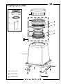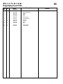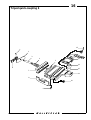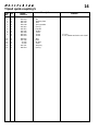
1
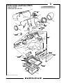
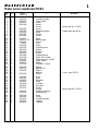
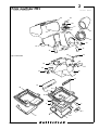
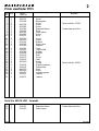
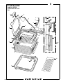
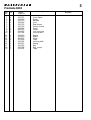
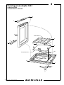
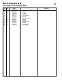
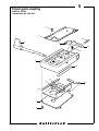
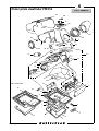
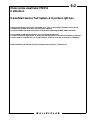
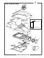
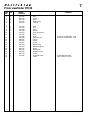
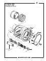
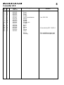
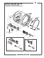
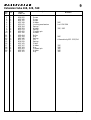
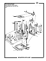
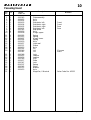
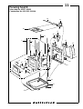
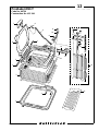
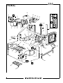
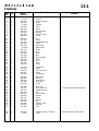
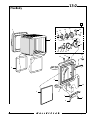
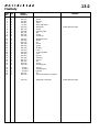
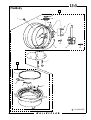
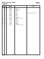
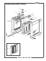
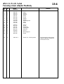
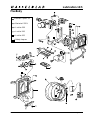
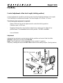
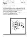
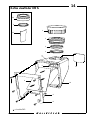
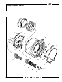
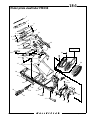
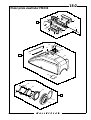
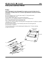
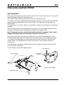
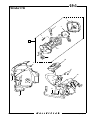
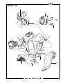
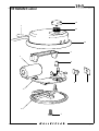
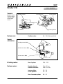
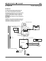
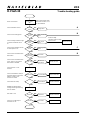
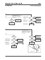
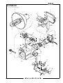
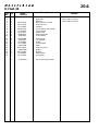
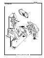
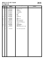
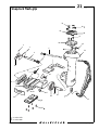
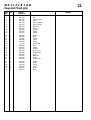
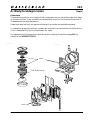
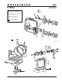
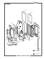
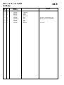
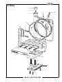
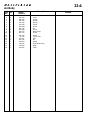
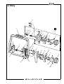
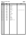
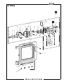
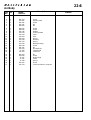
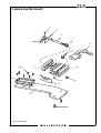
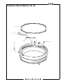
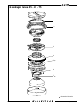
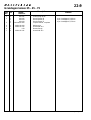
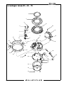
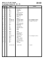
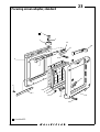
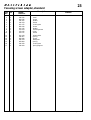
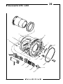
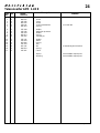
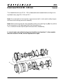
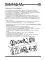
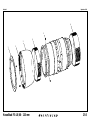
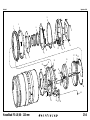
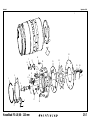
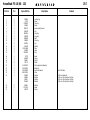
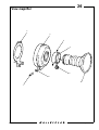
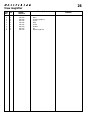
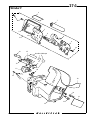
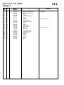
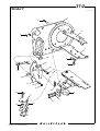
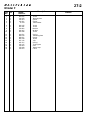
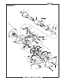
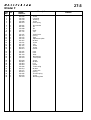
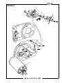
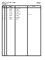
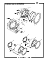
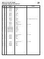
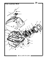
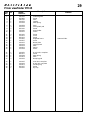
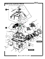
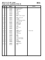
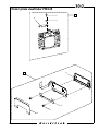
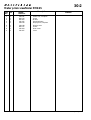
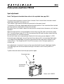
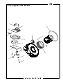
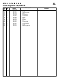
Service Manual Accessories III May 1993 Victor Hasselblad AB Göteborg Sweden Copyright © 1998 by Victor Hasselblad AB. All rights reserved. No parts of this material may be reproduced, stored in retrieval system or transmitted, in any form or by any means, electronic, mechanical, photocopy, recording, or otherwise, without the prior written permission of the Company. Contents list Accessories III 1. Meter prism viewfinder PME5 2. Prism viewfinder PM5 3. Proshade 6093 4. Focusing screen adapter SWC 5. Tripod quick-coupling 6. Meter prism viewfinder PME51 7. Prism viewfinder PM90 8. Converter 2XE 9. Extension tube 16E, 32E, 56E 10. Standard focusing hood 11. Focucing hood E 12. Proshade 6093-T 13. FlexBody 14. Reflex viewfinder RMfx 15. Magnifying hood HM2 16. Tripod quick-coupling S 17. Teleconverter 1.4XE 18. Meter prism viewfinder PME90 19. Winder CW 20. D-Flash 40 21. Snap-lock flash grip 22. ArcBody 23. Focusing screen adapter, standard Revision 1 1. April 1998 Contents list Accessories III 24. Teleconverter APO1.4XE 25. Zoom lens FE 4.8/60 - 120 mm 26. View magnifier 27. Winder F 28. Extension tube 16, 32, 56 TCC 29. Prism viewfinder PM45 30. Meter prism viewfinder PME45 31. View magnifier PM45/PME45 Revision 4 2. January 2001 Related Service Infos Accessories 15/93 Meter prism viewfinder PME90 18/93 Meter prism viewfinder PME, PME3 and PME5 19/93 Meter prism viewfinder PME51 21/95 Proshade 6093-T 06/96 Prism viewfinder PM5 and PME51 07/96 FlexBody 13/96 D-Flash 40 15/96 Winder CW 16/96 Meter prism viewfinder PME90 02/97 IR Remote control and Winder CW 03/97 Winder CW 08/97 Prism viewfinder PM5 and PME51 09/97 Prism viewfinder PM5 and PME51 13/97 Winder CW 18/97 Winder CW 21/97 FlexBody 22/97 FlexBody focusing screen 23/97 Tripod quick-coupling S 30/97 ArcBody 32/97 Winder CW 02/98 D-Flash 40 04/98 IR Remote control 05/98 Snap lock flash grip Revision 0 1. October 1998 Related Service Infos Accessories 06/98 FlexBody 10/98 ArcBody and Grandagon lenses 11/98 Teleconverter APO 1.4XE 11/99 Zoom lens FE 4.8/60 - 120 mm 12/99 View magnifier 01/00 New CD-ROM - Version 1.2 03/00 Prism viewfinder PM90 04/00 Prism viewfinder PM45 06/00 Meter prism viewfinder PME45 07/00 Meter prism viewfinder PME45 and VHABSTS 09/00 New CD-ROM - Version 1.3 12/00 Winder CW 04/01 New CD-ROM - Version 2.0 Revision 4 2. January 2001 1 Meter prism viewfinder PME5 Code No. 42295 Construction No. 414 003 PME5.EPS Link to: VHABSTS 930326 44 43 42 41 40 45 5 PME 39 38 30 37 32 35 M A A S X A 31 33 36 B A T 34 RED 24 BLACK ORANGE BLUE YELLOW 29 23 19 28 25 22 21 26 27 20 15 14 12 1 16 13 19 17 V6 10 2 18 11 9 8 3 7 4 6 5 COPYRIGHT © 1993 ANDERS ENGSTRÖM ANDERS ENGSTRÖM, ILLUSTRATÖR Östra vägen 46 430 91 HÖNÖ TEL/FAX 031-96 84 64 Revision 1 February 2000 1 Meter prism viewfinder PME5 Pos Pcs No. 1 2 3 4 5 6 7 8 9 10 11 12 13 14 15 16 17 18 19 20 21 22 23 24 25 26 27 28 29 30 31 32 33 34 35 36 37 38 39 40 41 42 43 44 45 Revision 1 1 1 2 4 1 2 1 1 1 2 1 1 1 1 1 1 2 1 2 1 1 1 1 1 1 1 1 1 1 5 1 1 1 1 1 1 2 1 1 1 1 3 1 1 1 Spare Part No. 414 500 414 497 823 679 826 009 823 685 414 360 414 361 414 362 825 862 414 431 414 417 -01 414 407 13 455 414 325 414 104 810 524 810 540 820 650 414 044 414 366 414 022 414 491 414 413 414 106 814 523 414 102 414 454 820 630 414 401 414 322 414 410 414 403 414 499 414 411 820 670 414 424 414 434 414 108 824 604 405 412 414 421 414 420 Description Insulation plate Light shield Screw Screw Cover Screw Engraved frame Shim Frame Screw Shim Battery sign Cover Disc Prism Display prism Spacer Washer Screw Display board Photo cell holder Metering unit, compl. Light shield Button Indicator, compl. Spring Battery lid Cable Battery Screw Ring Shell Window Plate Diffusor Window Screw Ocular Rubber eyepiece Plate spring Shoe Screw Insulating plate Leather Leather Remark Sales code No. 52191 Please state serial No. 6 volt, type PX28 Sales code No. 42412 February 2000 2 Prism viewfinder PM5 COPYRIGHT © 1997 ANDERS ENGSTRÖM PM501.EPS ANDERS ENGSTRÖM, ILLUSTRATÖR Östra vägen 46 430 91 HÖNÖ tel/fax 031- 96 84 64 [email protected] 970213 30 29 28 27 26 25 31 24 23 12 20 21 21 22 19 = Loctite 480 12 18 14 17 13 16 12 15 11 33 10 9 8 7 6 1 2 32 5 4 Revision 1 3 February 1997 2 Prism viewfinder PM5 Pos Pcs No. 1 2 3 4 5 6 7 8 9 10 11 12 13 14 15 16 17 18 19 20 21 22 23 24 25 26 27 28 29 30 31 2 1 1 4 2 1 1 1 2 1 1 7 1 1 1 1 1 1 1 1 2 1 2 1 1 1 1 3 1 1 1 Description Spare Part No. 826 007 414 566 826 009 823 685 414 360 414 361 414 362 825 862 414 431 414 350 830 440 414 345 414 342 414 368 414 325 414 491 414 366 414 404 414 330 414 472 414 403 830 460 414 424 414 434 406 110 829 660 405 412 414 421 414 471 Screw Name plate Cover Screw Screw Engraved frame Shim Prism frame Screw Shim Cover Screw Bracket Prism cover Support Prism Light shield Holder Bracket Shell Cover Plate Screw Ocular Rubber eyepiece Plate spring Shoe Screw Insulating plate Leather Leather Remark Sales code No. 52191 Please state serial No. Sales code No. 42412 Serial No. 401EU1001 - forwards 32 33 Revision 2 1 1 414 387 414 800 Engraved frame Prism frame Please state serial No. May 2000 3 Proshade 6093 PROSHADE.EPS Code No. 40738 Construction No. 415 334 930324 7 8 8 2 9 10 14 8 4 15 6 11 12 16 13 17 5 4 18 3 19 2 1 Revision 0 COPYRIGHT © 1993 ANDERS ENGSTRÖM ANDERS ENGSTRÖM, ILLUSTRATÖR Östra vägen 46 430 91 HÖNÖ TEL/FAX 031-96 84 64 May 1993 3 Proshade 6093 Pos Pcs No. 1 2 3 4 5 6 7 8 9 10 11 12 13 14 15 16 17 18 19 Revision 0 1 4 1 2 1 1 1 5 1 1 1 1 1 2 1 1 1 1 1 Spare Part No. 415 371 415 419 415 370 415 446 415 335 415 336 415 444 826 010 415 445 415 384 415 410 415 440 415 447 415 408 415 385 815 857 415 369 415 386 415 454 Description Remark Front frame Screw Bellows Joint Rear frame Interm. frame Catch Screw Link coupling Locking arm Spring Brake Lifter Plate Locking shaft Spring Rail Rail, compl. Tape May 1993 4 Focusing screen adapter SWC Mattskiveadapter SWC.EPS 930219 Code No. 41050 Construction No. 402 348 5 4 3 Matt surface 6 2 8 1 7 9 10 Smooth surface 11 1 12 COPYRIGHT © 1993 ANDERS ENGSTRÖM Revision 0 ANDERS ENGSTRÖM, ILLUSTRATÖR Östra vägen 46 430 91 HÖNÖ TEL/FAX 031-96 84 64 May 1993 4 Focusing screen adapter SWC Pos Pcs No. 1 2 3 4 5 6 7 8 9 10 11 12 Revision 0 3 1 1 1 1 1 4 2 1 2 1 1 Spare Part No. 830 440 402 476 402 324 402 475 815 808 413 321 402 477 402 480 413 421 402 478 402 302 402 325 Description Remark Screw Holder Frame Locking arm Spring Focusing screen Spacer Spacer Fresnel lens Spring Rear plate Locking arm May 1993 5 SNABBKPL.EPS Tripod quick-coupling Code No. 45130 Construction No. 406 002 930518 1 2 14 4 3 13 12 5 11 6 7 10 8 9 1 COPYRIGHT © 1993 ANDERS ENGSTRÖM Revision 0 ANDERS ENGSTRÖM, ILLUSTRATÖR Östra vägen 46 430 91 HÖNÖ TEL/FAX 031-96 84 64 May 1993 5 Tripod quick-coupling Pos Pcs No. 1 2 3 4 5 6 7 8 9 10 11 12 13 14 Revision 0 6 1 1 1 1 1 1 1 1 1 1 1 1 1 Spare Part No. 829 640 406 402 817 115 406 344 406 301 406 410 406 409 406 406 406 405 406 408 406 407 815 803 406 342 406 404 Description Remark Screw Plate Clip Handle Base Spring Spring Guide Plate Spring Plate Spring Pawl Pin May 1993 6 COPYRIGHT © 1997 ANDERS ENGSTRÖM Meter prism viewfinder PME51 PME5101.EPS ANDERS ENGSTRÖM, ILLUSTRATÖR Östra vägen 46 430 91 HÖNÖ tel/fax 031- 96 84 64 [email protected] 970213 Link to: VHABSTS 39 38 37 36 35 40 34 33 18 2 29 31 32 M A A S X A 30 28 BLACK RED BLUE ORANGE YELLOW 22 27 20 RED GREEN 21 18 23 26 24 25 15 14 = Loctite 480 16 13 19 18 42 12 V6 1 17 11 10 9 8 7 41 2 3 6 4 5 Revision 2 January 2001 6 Meter prism viewfinder PME51 Pos Pcs No. 1 2 3 4 5 6 7 8 9 10 11 12 13 14 15 16 17 18 19 20 21 22 23 24 25 26 27 28 29 30 31 32 33 34 35 36 37 38 39 40 1 4 1 1 4 2 1 1 1 2 1 1 1 1 1 1 1 7 2 1 1 1 1 1 1 1 1 1 1 1 1 1 1 1 1 1 1 3 1 1 1 Description Spare Part No. 414 497 830 460 414 567 826 009 823 685 414 360 414 361 414 362 825 862 414 431 414 417 414 407 13 455 414 325 414 104 810 540 830 440 810 524 414 022 414 491 414 413 414 106 814 523 414 102 414 454 414 401 414 322 414 410 414 403 414 472 414 424 414 429 414 434 406 110 829 660 405 412 414 421 414 420 Light shield Screw Name plate Cover Screw Screw Engraved frame Shim Prism frame Screw Shim Battery sign Cover Disc Prism Display prism Washer Screw Spacer Metering unit, compl. Light shield Button Indicator, compl. Spring Battery lid Cable Battery Ring Shell Window Plate Cover Ocular Rubber eyepiece Rubber ring Plate spring Shoe Screw Insulating plate Leather Leather Remark Sales code No. 52191 Please state serial No. 6 volt, type PX28 Sales code No. 42412 Standard Optional Serial No. 402EU1001 - forwards 41 42 Revision 2 1 1 414 387 414 800 Engraved frame Prism frame Please state serial No. May 2000 6:1 Meter prism viewfinder PME51 Calibration Use the following equipment for calibration work: Light box Test shell 901654 Camera body (500 or 2000) Planar lens 2.8/80 Focusing screen Acute Matte (Hasselblad Service Test System) NOTE! Using a 203FE/205FCC/TCC camera body will give an error of approx. 0.1 EV due to the partially transparent mirror and is therefore normally not recommended. CAUTION! When handling the circuit board a grounded bench mat and a wrist strap must be used to prevent ESD damage. RV6 RV22 RV20 NOTE! Potentiometer RV20 and RV22 are pre-adjusted and sealed. They must not be touched. Setup for calibration: PME51 ISO/ASA Max f 100 2.8 Planar 2.8/80 Aperture Focus 2.8 Light box* EV K-factor 12 1.04 Light box** LL 9 ¥ See page 6:2 Attach the test shell 901654 and install a battery. Fit the finder to the camera body. Connect the camera body to the light box. Adjust the potentiometer RV6 so that LED 11 is lighting up and LED 12 is twinkling (0.25 EV accuracy). * Light box type "Kyoritsu" with fixed light levels in EV. ** Light box type "Spectron" with infinitely variable light levels in LL. Revision 1 February 2000 Meter prism viewfinder PME51 Calibration 6:2 Hasselblad Service Test System & Kyoritsu Light box In the present version of the Service Test System (Ver. 1.5/1.6) the message "Set light source to K=1.3" is displayed in the PME mode when using a Kyoritsu light box. This to get suitable light levels equivalent to 1/2stops when calibrating the PME, PME3 and PME5. For the PME51 a light level equivalent to a 1/4 or 3/4 stop must be used. Therefore measure the light box EV 12 setting with the test system. During the measurement try different K-factors until an acceptable 1/4 or 3/4 level is reached. (Either one can later on be used for calibration). PME51 calibration should then be made according to the instruction, Calibration 6:1 Revision 0 September 1993 7 Prism viewfinder PM90 COPYRIGHT ' 1999 1 ANDERS ENGSTR M PM90/01.EPS SVART 991221 2 ANDERS ENGSTR M, ILLUSTRAT R stra v gen 46 430 91 H N TEL/FAX 031- 96 84 64 [email protected] 3 4 5 6 Serial No. 411EE1700 - fwd 7 9 8 10 Prism protection Double-sided tape 11 Protective foil 12 13 14 15 16 21 20 19 22 18 17 23 Revision 1 February 2000 7 Prism viewfinder PM90 Pos Pcs No. Spare Part No. Description 1 2 3 4 5 1 3 1 1 1 405 412 829 660 406 110 414 434 414 550 Plate Screw Shoe Plate spring Leather 6 7 8 9 10 1 1 1 1 1 414 492 414 576 414 403 414 383 414 553 Shell Pad Plate Holder Prism protection 11 12 13 14 15 1 1 1 1 1 1 414 331 414 332 415 468 816 931 414 493 414 561 Prism Prism Protective foil Spring Frame Ocular 16 17 18 19 20 1 1 6 1 1 414 429 414 424 826 022 414 560 414 385 Rubber ring Rubber eyepiece Screw Name plate Magazine catch 21 22 23 2 1 1 826 014 414 387 Screw Engraved frame Cover Revision 3 Remark Serial No. 411EE1700 - fwd Serial No. 411EE1700 - fwd Please state serial No. Sales code No. 52191 January 2001 8 Converter 2XE Sales code No. 20605 Construction No. 435 007 CONV2XE.EPS Converter 2XE SVART 940421 1 2 14 3 1 16 15 5 6 4 14 13 12 7 Reflection protector "Palpas" 8 11 9 10 COPYRIGHT © 1994 ANDERS ENGSTRÖM ANDERS ENGSTRÖM, ILLUSTRATÖR Östra vägen 46 TEL/FAX 031- 96 84 64 430 91 Revision 0 HÖNÖ April 1994 8 Converter 2XE Pos Pcs No. 1 2 3 4 5 6 7 8 9 10 11 12 13 14 15 16 3 1 2 1 1 1 1 4 4 1 1 1 1 6 1 1 Spare Part No. 826 002 435 342 829 325 435 110 435 041 816 304 435 353 815 513 435 402 435 111 435 404 435 109 403 346 812 311 816 929 435 341 Description Screw Cover Screw Holder Locking mechanism Spring Holder Spring Contact pin Holder Roller Key Spring Pin Spring Catch Optics Housing Revision 1 Remark Incl. 816 304 Alternatively 812 313/314 Not available as spare part Not available as spare part August 1995 9 Extension tube 16E, 32E, 56E Sales code No. 40654, 40655, 40656 Construction No. 435 004, 435 005, 435 006 EXTNSN56.EPS Mellanringar 16, 32, 56 950813 1 14 2 3 1 16 15 5 6 4 14 13 12 7 Reflection protector "Palpas" 8 11 9 10 17 19 18 Extension tube 32E 20 21 Extension tube 16E COPYRIGHT © 1995 ANDERS ENGSTRÖM ANDERS ENGSTRÖM, ILLUSTRATÖR Östra vägen 46 430 91 HÖNÖ TEL/FAX 031- 96 84 64 Revision 0 August 1995 9 Extension tube 16E, 32E, 56E Pos Pcs No. 1 2 3 4 5 6 7 8 9 10 11 12 13 14 15 16 17 18 19 20 21 Revision 0 3 1 2 1 1 1 1 4 4 1 1 1 1 6 1 1 1 1 4 1 1 Spare Part No. 826 002 435 342 829 325 435 108 435 041 816 304 435 353 815 513 435 402 435 106 435 404 435 104 403 346 812 311 816 929 435 341 435 107 435 103 435 403 435 105 435 101 Description Screw Cover Screw Holder Locking mechanism Spring Holder Spring Contact pin Holder Roller Key Spring Pin Spring Catch Holder Key Contact pin Holder Key Remark 56E Incl. 816 304 32E, 56E 56E Alternatively 812 313/314 32E 32E 16E 16E 16E August 1995 10 Focusing hood Sales code No. 42315, 42323 Construction No. 416 001, 416 002 FOCHOOD.EPS Focusing hood standard 950616 30 11 31 29 28 27 18 1 25 2 24 23 3 26 4 7 5 22 8 9 10 21 11 20 12 6 13 14 19 18 17 16 15 COPYRIGHT © 1995 ANDERS ENGSTRÖM ANDERS ENGSTRÖM, ILLUSTRATÖR Östra vägen 46 430 91 HÖNÖ TEL/FAX 031-96 84 64 Revision 1 August 1995 10 Focusing hood Pos Pcs No. 1 2 3 4 5 6 7 8 9 10 11 12 13 14 15 16 17 18 19 20 21 22 23 24 25 26 27 28 29 30 31 Revision 1 1 2 2 1 1 1 1 1 4 1 3 2 1 2 1 1 1 4 1 1 1 1 1 1 1 1 1 1 1 1 1 1 Spare Part No. 416 043 416 415 416 414 416 403 416 404 416 402 416 401 416 342 416 416 416 408 816 925 815 612 416 407 816 924 416 419 416 427 416 111 416 413 836 001 416 040 416 041 416 348 416 425 416 426 416 346 416 417 416 347 814 507 416 345 416 112 416 423 Description Plate assembly Axle Axle Side plate, left Side plate, right Side plate, right Side plate, left Rear plate Axle Hinge, upper Spring Spring Hinge, lower Spring Axle Light seal Frame Axle Pin Lid Lid Lock Leather Leather Grip Plate Lock Spring Catch Bracket Axle Magnifier, 0 Neutral Remark Front Front Rear Rear Chrome Black Sales Code No. 42331 August 1995 11 Focusing hood E Sales code No. 42317, 42325 Construction No. 416 003, 416 004 FOCHOODE.EPS Focusing hood E 950616 29 11 30 28 27 26 18 1 24 2 23 22 3 25 4 7 5 21 8 9 10 20 11 19 12 6 13 14 18 17 16 15 COPYRIGHT © 1995 ANDERS ENGSTRÖM ANDERS ENGSTRÖM, ILLUSTRATÖR Östra vägen 46 430 91 HÖNÖ TEL/FAX 031-96 84 64 Revision 0 August 1995 11 Focusing hood E Pos Pcs No. 1 2 3 4 5 6 7 8 9 10 11 12 13 14 15 16 17 18 19 20 21 22 23 24 25 26 27 28 29 30 Revision 0 1 2 2 1 1 1 1 1 4 1 3 2 1 2 1 2 1 4 1 1 1 1 1 1 1 1 1 1 1 1 1 Spare Part No. 416 044 416 415 416 414 416 403 416 404 416 402 416 354 416 342 416 416 416 408 816 925 815 612 416 407 816 924 416 419 416 428 416 460 416 413 416 045 416 046 416 348 416 425 416 426 416 346 416 417 416 347 814 507 416 345 416 112 416 423 Description Plate assembly Axle Axle Side plate, left Side plate, right Side plate, right Side plate, left Rear plate Axle Hinge, upper Spring Spring Hinge, lower Spring Axle Light seal Frame Axle Lid Lid Lock Leather Leather Grip Plate Lock Spring Catch Bracket Axle Magnifier, -1 Diopters Remark Front Front Rear Rear Chrome Black Sales Code No. 42374 August 1995 12 Proshade 6093-T PRSHADE1.EPS Code No. 40739 Construction No. 415 390 7 950904 8 8 9 2 10 15 8 4 16 6 11 17 18 12 13 14 5 20 4 3 19 21 2 1 COPYRIGHT © 1993 ANDERS ENGSTRÖM Revision 0 ANDERS ENGSTRÖM, ILLUSTRATÖR Östra vägen 46 430 91 HÖNÖ TEL/FAX 031-96 84 64 September 1995 12 Proshade 6093-T Pos Pcs No. 1 2 3 4 5 6 7 8 9 10 11 12 13 14 15 16 17 18 19 20 21 Revision 0 1 4 1 2 1 1 1 5 1 1 2 2 1 1 2 1 1 1 1 1 1 Spare Part No. 415 371 415 419 415 370 415 446 415 335 415 336 415 444 826 010 415 445 415 384 815 708 415 413 415 440 415 447 415 408 415 385 815 857 415 457 415 458 415 391 415 454 Description Remark Front frame Screw Bellows Joint Rear frame Interm. frame Catch Screw Link coupling Locking arm Spring Pin Brake Lifter Plate Locking shaft Spring Rack, long Rack, short Rail, compl. Tape September 1995 13:1 FlexBody COPYRIGHT © 1997 ANDERS ENGSTRÖM FLXBDY01.EPS ANDERS ENGSTRÖM, ILLUSTRATÖR Östra vägen 46 430 91 HÖNÖ tel/fax 031- 96 84 64 [email protected] 970528 47 1 2 45 3 44 46 49 43 42 48 41 7 8 4 5 6 11 40 9 39 10 38 12 7 37 13 32 7 33 14 15 36 17 17 16 35 18 20 34 17 19 31 32 25 24 21 23 22 30 1 2 29 28 26 27 Revision 1 August 1997 13:1 FlexBody Pos Pcs No. Spare Part No. Description 1 2 3 4 5 2 2 2 1 1 13 379 109 101 821 820 12 166 109 354 Leather Knob, complete Screw Leather Knob 6 7 8 9 10 2 3 1 1 2 825 960 810 919 109 422 109 360 821 663 Screw Spring washer Bearing Support, outer Screw 11 12 13 14 15 1 1 1 2 1 812 503 109 367 109 341 824 963 825 764 Pin Guide Intermediate part Screw Stop screw 16 17 18 19 20 1 4 1 1 1 13 190 -1 825 733 109 352 109 330 109 353 Name plate Screw Rod Slider Nut 21 22 23 24 25 1 2 1 1 1 810 958 824 964 109 355 109 349 825 704 Spring washer Screw Pin Foot Screw 26 27 28 29 30 1 6 1 2 1 30 763 829 790 109 022 821 911 109 356 Tripod foot Screw Foot, complete Screw Attachment 31 32 33 34 35 1 2 1 1 4 109 366 840 906 109 419 109 362 823 451 Plate, right Bearing Locking ring Plate, left Screw 36 37 38 39 40 41 1 2 1 1 1 1 109 364 109 405 109 347 812 903 109 415 109 453 Gear ring Shim (0,05mm) Adjusting screw Pin Shrink sleeve Leather 42 43 44 45 46 47 3 1 2 1 2 1 825 732 840 905 812 705 109 361 109 363 109 365 Screw Bearing Pin Support, inner Slide bar Gear 48 49 1 1 109 346 13 456 Adjusting screw, complete Level Revision 1 Remark Alternatively 109 409 (0,10mm) Below Serial No. 451EU1308 " August 1997 13:2 FlexBody COPYRIGHT © 1997 ANDERS ENGSTRÖM FLXBDY02.EPS ANDERS ENGSTRÖM, ILLUSTRATÖR Östra vägen 46 430 91 HÖNÖ tel/fax 031- 96 84 64 [email protected] 970514 30 1 24 25 26 27 28 29 23 2 22 21 20 19 15 16 17 18 14 13 12 11 3 5 10 4 6 7 9 8 Revision 1 August 1997 13:2 FlexBody Pos Pcs No. Spare Part No. Description 1 2 3 4 5 1 1 2 1 1 109 357 109 301 109 421 22 807 109 322 Frame Bellows Tape Stray light mask Rear plate 6 7 8 9 10 1 1 2 4 1 825 733 109 401 812 311 821 661 109 359 Screw Support plate Pin Screw Guide pin 11 12 13 14 15 1 2 2 2 1 109 402 308 447 812 202 820 430 830 060 Magazine hook Screw Pin Screw Screw 16 17 18 19 20 1 1 1 1 1 810 736 109 414 109 413 109 403 109 424 Washer Latch Locking washer Gear Spring 21 22 23 24 25 1 1 1 2 1 109 342 815 754 811 201 823 015 109 343 Housing Spring Pin Screw Driving shaft 26 27 28 29 30 1 1 1 1 1 13 826 30 484 -1 13 810 -1 812 207 109 025 Spring Crank support Handle Pin Crank mechanism, complete 109 024 Rear plate, complete Revision 1 Remark Please state serial No. Please state serial No. August 1997 13:3 FlexBody FLXBDY03.EPS 20 960610 1 19 18 17 16 15 14 8 9 11 10 12 13 7 2 3 4 5 6 COPYRIGHT © 1996 ANDERS ENGSTRÖM ANDERS ENGSTRÖM, ILLUSTRATÖR Östra vägen 46 430 91 HÖNÖ TEL/FAX 031-96 84 64 = Loctite 638 Revision 1 February 1998 13:3 FlexBody Pos Pcs No. Description Spare Part No. 1 2 3 4 5 4 1 1 1 1 821 460 109 049 403 346 435 341 816 929 Screw Lens holder Spring Catch Spring 6 7 8 9 10 6 2 1 1 1 812 311 821 910 13 411 811 201 21 519 Pin Screw Rod Pin Spring 11 12 13 14 15 1 1 2 1 1 109 116 21 514 820 016 13 774 13 777 Washer Mechanism, complete Screw Catch Cover 16 17 18 19 20 1 1 1 1 1 13 779 825 002 13 778 109 429 109 021 Socket Screw Knob Sign plate Lens holder, complete Revision 1 Remark Alternatively 812 313/314 February 1998 13:4 Focusing screen adapter FlexBody FLXBDY10.EPS COPYRIGHT © 1997 ANDERS ENGSTRÖM 970521 ANDERS ENGSTRÖM, ILLUSTRATÖR Östra vägen 46 430 91 HÖNÖ tel/fax 031- 96 84 64 [email protected] 1 2 18 3 16 17 16 15 14 4 7 11 5 7 8 ANDERS ENGSTRÖM, ILLUSTRATÖR Östra vägen 46 430 91 HÖNÖ tel/fax 031- 96 84 64 [email protected] 10 11 6 COPYRIGHT © 1997 ANDERS ENGSTRÖM 9 13 FLXBDY11.EPS 970604 12 19 Revision 1 September 1997 13:4 Focusing screen adapter FlexBody Pos Pcs No. Spare Part No. Description 1 2 3 4 5 1 1 1 1 2 436 412 436 102 436 404 436 041 830 440 Level Holder Support Frame Screw 6 7 8 9 10 1 2 1 1 1 402 476 109 368 413 323 413 415 413 416 Holder Holder Focusing screen Glass Frame 11 12 13 14 15 2 4 1 1 1 436 407 823 783 436 321 402 475 809 030 Spring Screw Rear plate Locking arm Steel ball 16 17 18 2 1 1 815 808 436 409 829 435 Spring Spring support Screw 19 1 436 041 -1 Frame, incl. focusing screen Revision 1 Remark Previous type Focusing screen adapter FlexBody. (Please see Service Info 22/97) August 1997 Lubrication 13:5 FlexBody FLXBDY01.EPS 960624 = Isoflex Topas L32 = Barierta L25DL = Loctite 638 = Loctite 243 = Loctite 415 = Safety lacquer FLXBDY02.EPS 960806 COPYRIGHT © 1996 ANDERS ENGSTRÖM ANDERS ENGSTRÖM, ILLUSTRATÖR Östra vägen 46 430 91 HÖNÖ TEL/FAX 031-96 84 64 FLXBDY03.EPS 960610 Revision 0 August 1996 Repair 13:6 FlexBody Control/adjustment of the focal length (infinity position) Control/adjustment should be carried out each time the FlexBody has been in for repair. The FlexBody is so-called over focused. The focal length is 71.40 mm - 0.2 mm. The following test equipment is required: - Planar CF80 mm lens at full aperture with controlled infinity position. Deviation max. ± 0.03 mm. - Magazine fitted with a front surface coated mirror resting on the edges of the picture frame. The Hasselblad mirror with part No. 103 452 is suitable. - Lens collimator. Adjustment Adjust the lens extension mechanism to infinity position and control that the slider 109 330 is resting on the stop screw 825 764. Note! The tilt and shift controls should be in the neutral (0-) position. FLXBDY01.EPS Adjust by rotating the stop screw 825 764 and secure with safety lacquer. (See fig. below) 960624 825 764, stop screw 109 330, Slider COPYRIGHT © 1996 ANDERS ENGSTRÖM Revision 0 ANDERS ENGSTRÖM, ILLUSTRATÖR Östra vägen 46 430 91 HÖNÖ TEL/FAX 031-96 84 64 August 1996 Repair 13:7 FlexBody Centering the front mechanism (21 514) Mount the tool 902658 (V-2075) into the lens holder and connect tool 902918 (V-2219). Turn the key using 902918 to a vertical position. Check that the free play is even in both directions. If there is more resistance at one direction than the other move the front mechanism to obtain a balance. Carry out the same procedure with the key in a horizontal position. Also check at the 180o points in both vertical and horizontal position. When the key is centralised tighten both screws 820 016. The hole for the locating pin 811 201 is bored with 1.2 mm drill. Drive in the pin until it is on a level with the lens holder and secure it with loctite. Remove the swarf and lubricate the bevel gears with grease. FLXBDY03.EPS 960610 21 514 820 016 811 201 Revision 0 August 1996 14 Reflex viewfinder RMfx 13 4 1 12 2 3 4 5 11 6 10 7 9 8 = Loctite 243 Revision 0 September 1996 14 Reflex viewfinder RMfx Pos Pcs No. Spare Part No. Description 1 2 3 4 5 1 1 1 2 1 436 348 436 352 109 408 436 401 436 403 Rubber eyepiece Lens holder Lens Locking ring Locking ring 6 7 8 9 10 1 6 1 1 1 436 410 826 024 436 358 436 353 436 322 Mirror Screw Frame Holder Housing 11 12 13 1 1 1 436 402 436 411 436 347 Leather Key Lens holder Revision 0 Remark September 1996 15 Magnifying hood HM2 12 1 11 2 10 3 4 5 6 7 9 = Loctite 243 = Loctite 480 = Losoid 3342 Revision 0 8 September 1996 15 Magnifying hood HM2 Pos Pcs No. Spare Part No. Description 1 2 3 4 5 1 1 1 1 1 436 348 436 346 436 344 109 408 436 345 Rubber eyepiece Holder Ring Lens Lens Holder 6 7 8 9 10 1 1 6 1 1 436 101 436 350 826 024 436 358 436 411 Lens assembly Housing Screw Frame Key 11 12 1 1 436 401 436 347 Locking ring Lens holder Revision 0 Remark September 1996 16 Tripod quick-coupling S 15 1 2 3 14 4 5 13 6 12 7 11 8 10 9 Revision 0 September 1996 16 Tripod quick-coupling S Pos Pcs No. Spare Part No. Description 1 2 3 4 5 1 1 1 4 1 812 604 406 413 406 412 810 918 406 400 Pin Pressure plate Rod Spring washer Spring 6 7 8 9 1 1 1 1 1 406 322 406 345 406 399 825 905 825 904 Handle Holder Cover Screw Screw 10 11 12 13 14 15 1 1 1 1 1 1 828 905 406 346 13 455 13 456 406 321 816 934 Nut Base Washer Level Stop key Spring Revision 1 Remark 2.5 mm 3 mm, Please see Service Info 23/97 September 1997 17 Teleconverter 1.4XE CON1.4XE.EPS Converter 1.4XE COPYRIGHT © 1996 ANDERS ENGSTRÖM ANDERS ENGSTRÖM, ILLUSTRATÖR Östra vägen 46 430 91 HÖNÖ tel/fax 031- 96 84 64 [email protected] 960730 1 14 2 3 1 16 4 15 5 6 14 13 12 7 8 11 9 10 Revision 0 September 1996 17 Teleconverter 1.4XE Pos Pcs No. Description Spare Part No. 1 2 3 4 5 3 1 2 1 1 826 002 435 342 829 325 435 041 816 304 Screw Cover Screw Locking mechanism Spring 6 7 8 9 10 1 1 4 4 1 435 112 435 353 815 513 435 402 435 111 Holder Holder Spring Contact pin Holder 11 12 13 14 15 16 1 1 1 6 1 1 435 404 403 346 435 113 812 311 816 929 435 341 Roller Spring Key Pin Spring Catch Optics Housing Revision 0 Remark Incl. 816 304 Alternatively 812 313/314 Not available as spare part Not available as spare part September 1996 18:1 Meter prism viewfinder PME90 1 2 3 4 9 12 5 6 4 7 13 8 10 11 See page 18:2 33 14 15 16 36 17 4 18 35 19 34 20 33 21 24 22 23 25 28 26 32 29 27 30 31 12 Revision 0 September 1996 18:1 Meter prism viewfinder PME90 Pos Pcs No. Description Spare Part No. 1 2 3 4 5 1 1 1 8 1 414 616 414 392 414 654 830 016 414 612 Locking bar Light transmitter Diffusor Screw LCD 6 7 8 9 10 1 5 1 1 1 414 635 107 421 414 676 414 391 414 675 Rubber contact pad O-ring Display prism 1 Display prism 2 Insulator 11 12 13 14 15 1 1 1 4 1 414 655 414 395 414 696 414 576 414 336 Support Main PC board, complete Flex Pad Prism holder 16 17 18 19 20 4 1 1 1 6 826 018 414 332 414 669 414 387 826 022 Screw Prism Frame Engraved frame Screw 21 22 23 24 25 1 1 1 1 1 815 805 414 666 414 665 414 667 414 600 Spring Arm Arm Catch Name plate 26 27 28 29 30 3 1 1 2 1 826 020 414 672 414 606 414 582 414 388 Screw Cover Support Spot diaphragm Sensor unit, complete 31 32 33 34 35 36 1 2 4 1 1 1 414 631 826 017 826 019 414 617 414 607 414 597 Integral diaphragm Screw Screw Locking arm Catch Eye cup Cover Revision 0 Remark Incl. sensor board State serial No. Sales code No. 52191 September 1996 18:2 Meter prism viewfinder PME90 5 3 4 1 2 9 6 10 8 7 16 18 15 17 14 13 19 11 12 20 26 25 24 27 21 23 22 Revision 0 September 1996 18:2 Meter prism viewfinder PME90 Pos Pcs No. Description Spare Part No. 1 2 3 4 5 1 1 1 1 1 414 642 414 674 414 671 414 643 414 673 Control unit, complete Shaft Battery cover Contact spring Panel 6 7 8 9 10 1 1 1 1 3 414 396 414 670 414 659 414 652 826 018 Rubber keypad Circuit board Contact, Contact, + Screw 11 12 13 14 15 1 1 1 1 1 414 393 414 661 414 434-01 406 110 405 412 Housing, complete Housing Plate spring Shoe Plate 16 17 18 19 20 3 1 1 1 1 829 660 414 585 414 602 414 394 414 403 Screw Dome Leather Window Plate 21 22 23 24 25 1 1 1 1 1 414 390 414 618 414 662 414 640 414 641 Eye-piece unit, complete Focusing ring Locking clip Lens, outer Lens, inner 26 27 1 2 414 663 826 021 Spring Screw Battery Revision 1 Remark 3 volt, type CR-123A Lithium May 2000 18:3 Meter prism viewfinder PME90 Link to: VHABSTS Calibration: The PME90 has microprocessor controlled electronics. Variable resistors are eliminated. The calibration is done by software writing corrections into an EE-prom. Therefore the Hasselblad Service Test System and an IBM compatible PC must be used for calibration work. The procedure is described in the Service Test System user manual. Tolerances Exposure meter: Max. deviation ± 0.3 EV. Current Drain: Max. 50uA. CAUTION! When handling the circuit board a grounded bench mat and a wrist strap must be used to prevent ESD damage. Cleaning: Note! The figures in brackets below refers to the exploded view page 18:1. Remove the housing held by three screws (26). Separate the housing and the control unit. Disconnect the flex from the control unit. The prism: The prism is held in position by a prism holder (15) which is secured by four screws (16). After removal of the screws, the prism holder including the main PC board can be separated from the prism. Ensure that the two cables connecting the main PC board and the sensor board are not damaged. The prism can now be removed for cleaning. Note! The sensor unit and the eye-piece remains in position. The eye-piece unit: It consists of two glass lenses (three if a correction lens is installed) and is held in position by two screws. Remove the catch (35), the locking arm (34) and the screws (33). The eye-piece is now removable for cleaning. Note! The eye-piece must be rotated fully clockwise before it is removed. If not, it could damage the sensitive plastic lens mounted in the sensor unit next to it. The sensor unit: It is also held by two similar screws (33). Before it can be removed for cleaning, the two screws retaining the rear part of the main PC board must be removed. Note! Only a blower or a clean brush should be used for cleaning the plastic lens. If the lens is damaged, the complete unit should be changed. (Factory calibrated). Revision 2 May 2000 18:4 Meter prism viewfinder PME90 Display: Note! If the display has been disassembled for cleaning care must be taken when it is reassembled. The two prisms, the LCD and the light transmitter can easily be scratched. Reassembly: Mount the display prism 2 (1) with two screws (2). (Final position later). Mount the display prism 1 (3). Put the rubber contact pad (4) into the slot of the prism 1. Place the LCD (5) in position and push it to the left according to fig. 1. Note! The profile should face the right hand side. Cover the LCD with the diffusor (6) and make sure the upper end of the diffusor is placed underneath the PC board. Mount the light transmitter (7) and carefully secure with the locking bar (8). Re-check the LCD position. The final display position is set by adjusting the display prism 2 (1) when viewing through the eye-piece. Display position adjustment Profile 2 Fig. 1 8 1 7 6 5 4 Fig. 2 3 Revision 0 September 1996 18:5 Meter prism viewfinder PME90 Spot adjustment: The spot metering system consists of two channels. Each channel has a mirror, a lens, and a metal diaphragm mounted in the sensor unit. Two sensors (light sensitive diode) are mounted on the sensor board. The position of the two diaphragms defines the spot position. Each one should be checked optically before an adjustment. (Instruction below). The diaphragms are secured with safety lacquer. Normally there is no need to adjust the spot position except when the sensor unit has been replaced. Before the spot position can be adjusted the eye-piece unit and the sensor board must be removed. The sensor board is attached to the sensor unit by two screws. Note! The eye-piece must be rotated fully clockwise before it is removed. If not, it could damage the sensitive plastic lens mounted in the sensor unit next to it. Mount the finder onto a camera body fitted with the focusing screen adapter V-4705. Illuminate each diaphragm (one at the time) from above with a concentrated light beam. The image of the diaphragm circle will be projected on the screen and is visible on the camera mirror. The image should fill the 12 mm screen circle if the spot position is correctly set. If an adjustment is required, the diaphragms can be moved according to the sketch until correct position is achieved. Do not forget to secure with safety lacquer. Illuminate here Spot diaphragms Adjustment directions Sensor unit 414388 Integral diaphragm Revision 0 September 1996 19:1 COPYRIGHT ' 2000 ANDERS ENGSTR M WINDCW01.EPS Winder CW ANDERS ENGSTR M, ILLUSTRAT R stra v gen 46 430 91 H N tel/fax 031- 96 84 64 [email protected] Winder CW 000913 5 3 4 2 1 6 8 7 18 9 17 16 14 10 13 12 15 11 Revision 1 January 2001 19:1 Winder CW Pos Pcs No. Spare Part No. Description 1 2 3 4 5 1 1 5 1 1 438 041 830 101 438 345 438 354 438 439 Battery compartment, compl. Screw Connection plate Locking lever Cover 6 7 8 9 10 1 1 2 2 1 438 324 438 348 438 472 438 448 22 404 Battery holder Connection plate Insulator Spacer Leather 11 12 13 14 15 1 1 1 1 1 438 111 820 383 438 416 826 010 438 456 Housing, outer Screw Sensor holder Screw Spacer 16 17 18 1 2 1 438 805 826 015 438 088 Contact flex Screw Mode selector Revision 2 Remark January 2001 WINDCW02.EPS Winder CW 19:2 Winder CW 961104 1 23 2 3 4 7 6 5 22 8 9 21 10 12 20 11 19 18 13 17 14 16 15 Revision 0 October 1996 19:2 Winder CW Pos Pcs No. Spare Part No. Description 1 2 3 4 5 1 2 1 1 2 438 110 810 509 814 804 814 903 817 115 Locking arm Washer Spring Spring Clip 6 7 8 9 10 1 1 1 1 1 438 435 438 112 438 800 826 027 438 021 Arm Clutch arm PC board Screw Winding unit, complete 11 12 13 14 15 1 1 1 1 3 438 341 438 449 438 042 814 904 829 660 Coupling Spacer Release unit, complete Spring Screw 16 17 18 19 20 1 1 1 1 3 438 120 438 116 438 437 438 106 826 030 Leather strap Plate Sleeve Housing, inner Screw 21 22 23 1 7 1 438 441 826 029 438 089 Tape Screw Bayonet plate Revision 3 Remark Please state serial No. February 1998 19:3 IR Remote Control WINDRM01.EPS Winder CW, fjärrkontroll COPYRIGHT © 1998 ANDERS ENGSTRÖM ANDERS ENGSTRÖM, ILLUSTRATÖR Östra vägen 46 430 91 HÖNÖ tel/fax 031- 96 84 64 [email protected] 980130 12 1 11 10 9 2 8 6 7 3 4 5 Revision 2 February 1998 19:3 IR Remote Control Pos Pcs No. Spare Part No. 1 2 3 4 5 1 1 1 1 2 439 101 439 322 830 560 Strap Battery PC board Cover Screw 6 7 8 9 10 1 1 1 1 1 439 401 439 403 438 442 439 405 439 321 Button Cover Stop pin Support Housing 11 12 1 1 815 812 438 445 Spring Exposure button Revision 2 439 402 Description Remark 3 volt, type CR-2 Lithium February 1998 19:4 Winder CW Specifications Winder CW: Compatibility: Hasselblad 503CW and 503CXi Modes: Single exposure, continuous exposure, multiple exposure, remote control and lock/off Winding speeds: 1.05 sec, approx. 0.8 frames/sec in continuous mode Battery requirement: 6 x AA pen cells (LR6) Weight: 360g (13 oz) excluding batteries Specification IR Remote Control: Battery requirement: 1 x CR-2 Weight: 55g (2 oz) Repair/Calibration: The Winder CW requires the following equipment: - Hasselblad Service Test System 970600 - Adapter Winder CW 970995 (incl. cables) - Torx T6 screw driver ZZ35 - 503CW camera body Revision 0 October 1996 19:5 Winder CW Disassembly: CAUTION! When handling the circuit board a grounded bench mat and a wrist strap must be used to prevent ESD damage. - Remove the battery compartment 438041. Unscrew 3 screws 829660 and 1 screw 826029, located to the right of the winder retaining slot. - Separate the inner/outer housing from each other and carefully loosen the IR-sensor (contact flex) from its attachment. - Disconnect the mode selector 438088 from the contact flex. - Rotate one of the gear wheels of the release unit 438042 in order to move the release arm from its outer to its inner (released) position. - Remove the sleeve 438437. - Loosen the contact flex of the release unit from the PC board. Loosen 3 screws 826030 and remove the plate 438116 and the release unit 438042. - Loosen the contact flex 438805 from the PC board. Loosen the screw 826027 and remove the board. - Loosen carefully the "on/off camera" switch (see page 19:7) which is held by a double-sided tape. - Loosen 2 screws 826015 and carefully remove the battery contacts. - Loosen 4 screws 826029 located closest to the coupling 438341 and remove the winding unit together with the contact flex. - Loosen the screws 820383 and 826010. Remove the "winding home" and the "winding counter" sensors from the winding unit (see page 19:7). Unsolder the contact flex. - Loosen the remaining 2 screws 826029 and remove the bayonet plate 438089. Remove the springs 814804 and 814903 and the arms 438110, 438112 and 438435. Revision 1 February 2000 19:6 Winder CW Reassembly: CAUTION! When handling the circuit board a grounded bench mat and a wrist strap must be used to prevent ESD damage. - Lubricate the arms 438110, 438112 and 438435 with Gleitmo 805 K and assemble together with the springs 814804 and 814903 on the bayonet plate 438089. - Solder the contact flex 438805 and fit the "winding home" and the "winding counter" sensors to the winding unit (see page 19:7). - Fit the winding unit in the inner housing and secure with 4 screws 826029. - Carefully fit the battery contacts and secure with 2 screws 826015. - If necessary, replace the double-sided tape 438441 and place the "on/off camera" switch in its attachment (see page 19:7). - Fit the PC-board and secure it with the screw 826027. Connect the contact flex to the PC-board. - Make sure that the release unit 438042 (release arm) is in the inner (released) position and place it in the inner housing. Fit the plate 438116 and secure with 3 screws 826030. Fit the sleeve 438437 on the release arm and connect the contact flex to the PC-board. - Connect the mode selector 438088 to the contact flex and place it in the inner housing. - Connect the battery compartment (incl batteries) or a power supply set on 9V. - Connect the winder to the Hasselblad Service Test System and then follow the instructions according to the STS "Users Instructions" (see page 19:7). - Fit the spacer 438449 in the inner housing and 2 spacers 438448 in the outer housing. Fit the IR-sensor in its attachment and reassemble the housings. Secure with 3 screws 829660 and 1 screw 826029. - Connect the winder to the Service Test System again and make a final check. Revision 1 February 2000 19:7 Winder CW Sensors: Link to: VHABSTS Release counter On/off camera Winding home Note! The gears must be rotated manually when checking the sensors. Release home Release arm Release arm: Sensor calibration: Winding counter Position value: 46 - 56 (Outer position) Winding sensor RV3 Release arm sensor RV1 Release sensor RV2 Winding motor: No. of pulses: 229 - 231 Release motor: Reaction time in: Reaction time out: Max. 50 ms Max. 150 ms Inner position: Outer position: 22 - 24 22 - 24 No. of excenter pulses: 89 - 91 Revision 0 October 1996 20:1 D-Flash 40 Trouble shooting guide WARNING! For safety reasons, the main capacitors MC1 and MC2, must be discharged before disassembly. TRBLBLOC.EPS 991011 Discharge the capacitors with a 100 ohm 9 W resistor connected between GND of the sync. socket and contact 2 on the flash tube socket according to the sketch below. The voltage of the capacitors can also be measured at these points. Capacitor C10, mounted on PCB 1059, must also be discharged according to the sketch but can only be reached after disassembly of the head case. Flash tube socket gray 4 1 2 3 V red Main Capacitors Resistor 100 ohm 9W white MC1 C10 MC2 black V red PCB1059 CN1B (7 pin connectors) Resistor 100 ohm 9W (8 pin connectors) CN1A CN3A PCB1056 CN3B PCB1055 red black High voltage socket VR1 CN5 blue J1 Revision 0 yellow February 1998 20:2 D-Flash 40 Power is turned on. Check oscillation sound. Trouble shooting guide Power switch ON Oscillation sound? Use a power supply with more than 9 VDC, 0.5 A or new batteries. NO A Charge failure YES Check if neon lamp glows. Neon lamp glows? NO YES Check if ready indication light in camera viewfinder turns on. ViewNO finder indication light? B Ready indication failure Ready signal failure Check if ready indication light on flash unit turns on. Check TTL cord YES Check if the oscillation sound is interrupted or not. Oscillation sound? NO C Voltage regulator failure YES Check if the unit flashes with test button. Flash with test button? NO D Flash failure YES Check if the unit flashes with synch. and TTL cord when the camera is released. Flash with synch. cord? NO Synchronize circuit failure Check TTL cord TTL circuit failure Replace PCB1056 Auto OK failure Replace PCB1056 Not full flash Replace PCB1056 Not low flash Replace PCB1056 YES Check the unit in TTL function. Check if the READY lamp is turned off during continuous flashing. Check if TTL function is normal. READY lamp? NO YES NO Check auto OK lamp. YES Release the shutter while cutting off the light entering lens on camera. Full flash or not. Full flash? NO YES Check if lo flash lamp is turned off or not. Low flash? NO YES Revision 0 February 1998 20:3 D-Flash 40 Trouble shooting guide A The voltage of the main capacitors (MC) can be measured between GND of the synchro terminal and pin 2 of the flash tube socket. B Adjust MC voltage with VR1 YES NOT GOOD Inspect the battery compartment and contacts. Replace battery compartment and/or contacts OK Short-circuit between pin 4 and pin 5 of CN3. Adjust voltage to 325–330V Oscillation sound? NO Replace PCB1056 NO YES Replace PCB1056 Defective BATTEXT-OFF switch. Replace PCB1055 C The voltage of the main capacitors (MC) can be measured between GND of the synchro terminal and pin 2 of the flash tube socket. D Is the flash tube normal? Check if the unit flashes when pins 8 and 6 on CN3 are short-circuited? Voltage of MC over 330V? YES Replace PCB1055 Voltage? Adjustable with VR1? NO Replace PCB1056 YES NO The voltage between pins 8 and 6 on CN3 must be 9–15V. Check MC for leakage. Replace PCB1056 or replace PCB1059 YES YES Flash? NO NO Replace PCB1056 Adjust VR1 to 325–330V YES Replace PCB1059 NO YES Adjust VR1 here Revision 0 February 1998 20:4 D-Flash 40 COPYRIGHT © 1998 ANDERS ENGSTRÖM DFLA4010.EPS ANDERS ENGSTRÖM, ILLUSTRATÖR Östra vägen 46 430 91 HÖNÖ tel/fax 031- 96 84 64 [email protected] 2 980128 4 3 5 1 12 9 7 13 8 6 15 10 11 14 17 16 18 19 Revision 0 20 February 1998 20:4 D-Flash 40 Pos Pcs No. Spare Part No. Description 1 2 3 4 5 1 1 1 1 1 K0455S02A MAC0550A ZAA7560A Flash tube Reflector Main capacitors, compl. Head case, rear Insulator 6 7 8 9 10 1 2 1 1 1 K0455S01A CAA8781A PAA7477A ENB0103A PAB1992A Circuit board, high voltage Locking screw Socket cover Flash tube socket Locking band 11 12 13 14 15 1 1 2 1 1 NEE0250D ASS0001A PAA5308A CAA7479A GBA7561B Locking ring Tilt assembly Holder Locking screw Label 16 17 18 19 20 1 1 1 1 2 MAD0380C PAB1978B MAC0630A CAA8601A GAA7540A Head case, front Holder Bracket Rotating disc Cover plate 1 ASF0360B Revision 0 Remark Sales code No. 55123 Sales code No. 55108 Set of various type screws February 1998 20:5 DFLA4020.EPS COPYRIGHT © 1998 ANDERS ENGSTRÖM D-Flash 40 ANDERS ENGSTRÖM, ILLUSTRATÖR Östra vägen 46 430 91 HÖNÖ tel/fax 031- 96 84 64 [email protected] 980202 21 1 19 5 2 4 3 6 18 17 8 7 9 10 14 15 11 12 20 13 16 Revision 0 February 1998 20:5 D-Flash 40 Pos Pcs No. Spare Part No. Description 1 2 3 4 5 1 1 1 1 1 MAD0472B MAB1848B MAA8200A K0455S03A MAA8610A Lower case, rear Selector Test button Circuit board Locking device 6 7 8 9 10 1 1 1 1 1 MAA8611A CAA8607A PAA8606A GNA3370A MAA8599A Holder Bolt Plate Cover Locking ring 11 12 13 14 15 1 1 1 1 1 PAA8600B RAA8797A CAB1983A ASZ0213A K0455S11A Plate Rubber ring Shoe High voltage socket Main circuit board 16 17 18 19 20 21 1 1 1 1 1 1 EXW0240A SAA8605A MAA8609A ASS0002A 13 190-1 K0455S54A TTL sync cord assembly Spring Locking lever Swivel assembly Name plate Battery compartment, compl. 1 ASF0360B Revision 0 Remark Set of various type screws February 1998 21 Snap-lock flash grip COPYRIGHT © 2001 ANDERS ENGSTR M SNAP01.EPS ANDERS ENGSTR M, ILLUSTRAT R 010129 stra vgen 46 430 91 H N tel/fax 031- 96 84 64 [email protected] 31 30 29 28 27 26 25 1 2 5 24 23 3 4 6 10 7 9 8 11 12 13 17 19 18 14 20 21 22 16 15 = Loctite 243 = Loctite 480 Revision 2 January 2001 21 Snap-lock flash grip Pos Pcs No. Description Spare Part No. 1 2 3 4 5 1 1 1 4 1 812 604 406 413 406 412 810 918 406 419 Pin Pressure plate Rod Spring washer Cable release 6 7 8 9 10 1 1 1 1 1 406 321 816 934 406 400 406 414 406 322 Stop key Spring Spring Screw Handle 11 12 13 14 15 1 1 1 1 6 406 345 406 325 825 905 406 399 829 760 Holder Base Screw Cover Screw 16 17 18 19 20 1 1 1 1 1 30 763 828 905 406 324 810 926 406 415 Tripod foot Nut Guide Washer Locking pin 21 22 23 24 25 1 1 1 2 1 406 416 406 353 406 350 829 845 406 417 Strap button Strap Basic grip Screw Strap holder 26 27 28 29 30 31 1 3 2 2 6 2 406 323 826 039 414 434 406 110 829 660 405 412 Holder Screw Spring Shoe Screw Plate Revision 3 Remark January 2001 22:1 ArcBody/Grandagon lenses Repair Please note! The parallelism and the focal length of the components are pre-set at the production stage by the use of shims. If the camera/lens is dismantled, be sure to include the shims when it is reassembled (see sketches below). Please note also that only the parts provided with a number are available as spares. In cases when spare parts without numbers are required, the camera/lens should be sent to Victor Hasselblad AB, Service Department for repair. For separating the focusing mount and the shutter, unscrew the shutter flange 013 by using the tool V000507700013. APO4501.EPS COPYRIGHT © 1997 ANDERS ENGSTRÖM 971125 ANDERS ENGSTRÖM, ILLUSTRATÖR Östra vägen 46 430 91 HÖNÖ tel/fax 031- 96 84 64 [email protected] COPYRIGHT © 1997 ANDERS ENGSTRÖM ARCBDY02.EPS 971031 ANDERS ENGSTRÖM, ILLUSTRATÖR Östra vägen 46 430 91 HÖNÖ tel/fax 031- 96 84 64 [email protected] Shims COPYRIGHT © 1998 ANDERS ENGSTRÖM 013, Shutter flange ANDERS ENGSTRÖM, ILLUSTRATÖR Östra vägen 46 430 91 HÖNÖ tel/fax 031- 96 84 64 [email protected] ARCBDY01.EPS 980127 Shims Revision 0 April 1998 ARCBDY03.EPS COPYRIGHT © 1997 ANDERS ENGSTRÖM 22:2 971125 ANDERS ENGSTRÖM, ILLUSTRATÖR Östra vägen 46 430 91 HÖNÖ tel/fax 031- 96 84 64 [email protected] ArcBody Lubrication = Isoflex Topas L32 = Barierta L25DL = Loctite 243 = Loctite 415 COPYRIGHT © 1997 ANDERS ENGSTRÖM ANDERS ENGSTRÖM, ILLUSTRATÖR Östra vägen 46 430 91 HÖNÖ tel/fax 031- 96 84 64 [email protected] ARCBDY02.EPS 971031 COPYRIGHT © 1997 ANDERS ENGSTRÖM ARCBDY04.EPS 971127 ANDERS ENGSTRÖM, ILLUSTRATÖR Östra vägen 46 430 91 HÖNÖ tel/fax 031- 96 84 64 [email protected] Revision 0 April 1998 22:3 ArcBody COPYRIGHT © 1998 ANDERS ENGSTRÖM ARCBDY01.EPS ANDERS ENGSTRÖM, ILLUSTRATÖR Östra vägen 46 430 91 HÖNÖ tel/fax 031- 96 84 64 [email protected] 980127 7 6 1 8 2 4 3 5 2 = Loctite 415 Revision 0 April 1998 22:3 ArcBody Pos Pcs No. Spare Part No. Description 1 2 3 4 1 2 2 1 109 462 436 412 824 967 109 463 Tilt scale Level Screw Shift scale 5 1 1 1 1 1 109 468 109 468 -1 109 421 109 469 109 058 Rod Rod Tape Tape Bellows 6 7 8 Revision 1 Remark Serial No. 452ER1286 - fwd Below Serial No. 452ER1286 Incl. tape September 1999 22:4 ArcBody ARCBDY02.EPS 1 COPYRIGHT © 1999 ANDERS ENGSTRÖM ANDERS ENGSTRÖM, ILLUSTRATÖR Östra vägen 46 430 91 HÖNÖ tel/fax 031- 96 84 64 [email protected] 990906 2 18 17 3 16 4 15 5 6 14 7 8 9 13 10 12 11 Revision 1 September 1999 22:4 ArcBody Pos Pcs No. Spare Part No. Description 1 2 3 4 5 1 1 1 1 1 436 412 829 435 436 102 109 476 109 383 Level Screw Holder Spring Guide 6 7 8 9 10 2 1 4 1 2 820 684 812 112 824 966 109 475 821 912 Screw Pin Screw Name plate Screw 11 12 13 14 15 4 1 1 4 1 829 790 30 735 109 397 812 311 816 929 Screw Tripod foot Foot Pin Spring 16 17 18 1 1 1 109 521 103 536 435 341 Foam plastic strip Index Catch Revision 1 Remark September 1999 22:5 ArcBody COPYRIGHT © 1998 ANDERS ENGSTRÖM ARCBDY03.EPS ANDERS ENGSTRÖM, ILLUSTRATÖR Östra vägen 46 430 91 HÖNÖ tel/fax 031- 96 84 64 [email protected] 980216 29 1 28 21 22 25 23 26 24 16 2 14 19 17 12 27 2 13 4 3 18 11 20 4 14 15 16 17 5 7 6 10 8 20 5 12 13 9 18 19 Revision 0 April 1998 22:5 ArcBody Pos Pcs No. Spare Part No. Description 1 2 3 4 5 1 5 1 2 2 13 190 -1 825 733 109 381 109 380 840 905 Name plate Screw Gear pinion Slide bar Bearing 6 7 8 9 10 1 1 4 1 2 109 376 810 907 823 451 109 364 109 405 Support, inner Washer Screw Gear ring Shim (0,05mm) 11 12 13 14 15 2 2 2 4 2 812 504 815 811 809 030 812 301 821 820 Pin Spring Steel ball Pin Screw 16 17 18 19 20 2 4 2 4 2 109 374 109 457 109 458 825 960 109 375 Lock handle Block brake Knob Screw Grip 21 22 23 24 25 1 1 1 1 2 817 132 810 809 109 455 109 454 109 467 Clip Washer Bearing Gear pinion Bearing 26 27 28 29 1 1 1 2 109 382 109 456 109 055 824 965 Shift housing Bearing Shift housing, complete Screw Revision 0 Remark Alternatively 109 409 (0,10mm) April 1998 22:6 ArcBody 27 ARCBDY04.EPS COPYRIGHT © 1997 ANDERS ENGSTRÖM 971127 ANDERS ENGSTRÖM, ILLUSTRATÖR Östra vägen 46 430 91 HÖNÖ tel/fax 031- 96 84 64 [email protected] 23 24 25 14 10 15 13 11 16 17 12 8 9 26 7 22 18 19 21 20 6 1 4 2 5 3 Revision 0 April 1998 22:6 ArcBody Pos Pcs No. Spare Part No. Description 1 2 3 4 5 1 1 4 2 1 825 704 109 401 821 661 812 311 812 805 Screw Support plate Screw Pin Pin 6 7 8 9 10 2 1 1 1 1 308 447 830 060 810 736 109 413 109 414 Screw Screw Washer Locking washer Latch 11 12 13 14 15 1 1 1 1 1 109 403 109 424 109 378 815 754 109 459 Gear Spring Housing Spring Bearing housing 16 17 18 19 20 3 1 1 1 1 826 018 811 201 109 379 22 335 412 104 Screw Pin Driving shaft Tooth wheel Crank arm 21 22 23 24 25 1 2 1 1 1 812 304 823 640 22 327 22 331 22 328 Pin Screw Nylon string Crank Spring 26 27 2 1 821 662 109 114 Screw Crank mechanism, complete Revision 0 Remark April 1998 22:7 COPYRIGHT © 1997 ANDERS ENGSTRÖM ADAP1801.EPS ANDERS ENGSTRÖM, ILLUSTRATÖR Östra vägen 46 430 91 HÖNÖ tel/fax 031- 96 84 64 [email protected] 971103 Camera inverter mount 2 3 4 5 1 17 6 7 9 16 8 10 15 14 13 11 12 = Loctite 243 Revision 0 April 1998 22:7 Camera inverter mount Pos Pcs No. Description Spare Part No. 1 2 3 4 5 1 1 1 1 4 406 322 812 604 406 413 406 412 810 918 Handle Pin Pressure plate Rod Spring washer 6 7 8 9 10 1 1 1 6 1 816 934 406 400 406 345 829 790 30 763 Spring Spring Holder Screw Tripod foot 11 12 13 14 15 1 2 1 1 1 109 388 824 968 406 399 825 905 828 905 Bar Screw Cover Screw Nut 16 17 1 1 109 398 406 321 Base Stop key Revision 0 Remark April 1998 Extension tube ArcBody 8, 16, 26 22:8 APOEXT01.EPS COPYRIGHT © 1997 ANDERS ENGSTRÖM 971204 ANDERS ENGSTRÖM, ILLUSTRATÖR Östra vägen 46 430 91 HÖNÖ tel/fax 031- 96 84 64 [email protected] 1 2 3 4 Revision 0 5 April 1998 22:8 Extension tube ArcBody 8, 16, 26 Pos Pcs No. 1 2 3 4 5 1 1 1 4 1 Description Spare Part No. 403 346 435 341 816 929 812 311 812 112 Spring Catch Spring Pin Pin Barrel Revision 0 Remark Not available as spare part April 1998 22:9 APO4501.EPS COPYRIGHT ' 2000 ANDERS ENGSTR M RODENSTOCK Apo-Grandagon 4,5/45 for Grandagon lenses 35 - 45 - 75 ANDERS ENGSTR M, ILLUSTRAT R stra v gen 46 430 91 H N tel/fax 031- 96 84 64 [email protected] 000828 ArcBody 1 2 3 4 4 5 6 7 = Secured with loctite Revision 1 September 2000 22:9 Grandagon lenses 35 - 45 - 75 Pos Pcs No. 1 2 Spare Part No. 3 1 1 1 1 1 109 471 109 062 109 063 109 064 1094-0000-100 4 5 6 7 1 3 1 3 2408-010-109 2408-015-112 013 2408-015-111 Revision 0 Description Locking ring 35/45 Front bayonet 35 Front bayonet 45 Front bayonet 75 Copal 0 shutter, complete Remark Apo-Grandagon 4,5/35mm Apo-Grandagon 4,5/45mm Apo-Grandagon 4,5/75mm Rubber grip Screw DIN 914 Shutter flange Screw DIN 912 January 2001 22:10 Grandagon lenses 35 - 45 - 75 COPAL01.EPS COPYRIGHT © 1998 ANDERS ENGSTRÖM 980213 ANDERS ENGSTRÖM, ILLUSTRATÖR Östra vägen 46 430 91 HÖNÖ tel/fax 031- 96 84 64 [email protected] 1 2 3 37 36 4 35 5 6 32 7 8 13 31 12 34 9 30 12 33 10 14 11 15 12 12 28 16 23 18 17 22 24 29 27 23 26 25 19 20 21 Revision 0 April 1998 22:10 Grandagon lenses 35 - 45 - 75 Pos Pcs No. Spare Part No. Description 1 2 3 4 5 1 1 1 1 1 012 011 301-3 301-6 301-5 Front plate nut Front plate Change lever Screw Change lever collar 6 7 8 9 10 1 1 1 1 2 301-4 301 301-2 301-1 113-1 Spring for 301-3 Main cocking lever Main spring collar Main spring Screw 11 12 13 1 4 1 1 1 113 111-1 0005-082-111 0005-081-116 0005-077-120 Sync socket Screw Diaphragm scale 35 Diaphragm scale 45 Diaphragm scale 75 14 15 16 17 18 2 1 1 1 1 102-1 102 110 301-7 107 Screw Cable release socket Shutter speed scale Nut for 301 Preview ring 19 20 21 22 23 1 1 3 2 3 108 109 109-1 107-2 107-5 Diaphragm ring Diaphragm retainer Screw Screw Screw 24 25 26 27 28 1 1 1 1 1 107-4 108-2 108-1 107-1 107-3 Screw Screw Diaphragm lever Preview knob Preview ring click 29 30 31 32 33 1 1 1 1 1 0005-082-117 402-1 402-2 401-1 401-2 Preview arm 35 Click spring Click Governor sheet A Governor sheet B 34 35 36 37 1 1 1 1 401-4 401 401-3 402 Set screw for 401 Slow speed governor Screw Timing dial 1094-0000-100 Copal 0 shutter Revision 0 Remark Apo-Grandagon 4,5/35mm Apo-Grandagon 4,5/45mm Grandagon-N 4,5/75mm Apo-Grandagon 4,5/35mm Complete April 1998 23 Focusing screen adapter, standard MATTAD01.EPS COPYRIGHT © 1997 ANDERS ENGSTRÖM 971204 ANDERS ENGSTRÖM, ILLUSTRATÖR Östra vägen 46 430 91 HÖNÖ tel/fax 031- 96 84 64 [email protected] 1 2 3 15 16 17 15 4 5 12 6 8 7 9 10 11 14 12 13 = Loctite 415 Revision 0 April 1998 23 Focusing screen adapter, standard Pos Pcs No. Spare Part No. Description 1 2 3 4 5 1 1 1 1 1 436 412 829 435 436 102 436 323 402 475 Level Screw Holder Frame Locking arm 6 7 8 9 10 2 1 1 1 1 830 440 402 476 413 323 413 415 109 517 Screw Holder Focusing screen Glass Frame 11 12 13 14 15 4 2 4 1 2 302 429 436 407 830 480 436 324 815 808 Glass holder Spring Screw Rear plate Spring 16 17 1 1 436 359 436 409 Locking arm Spring support Revision 0 Remark April 1998 24 Teleconverter APO 1.4XE . COPYRIGHT © 1998 APO1.4XE.EPS Converter APO 1.4XE ANDERS ENGSTRÖM ANDERS ENGSTRÖM, ILLUSTRATÖR Östra vägen 46 430 91 HÖNÖ tel/fax 031- 96 84 64 [email protected] 980320 1 15 2 3 1 17 16 4 6 5 15 7 14 13 8 9 12 10 11 Revision 0 April 1998 24 Teleconverter APO 1.4XE Pos Pcs No. Description Spare Part No. 1 2 3 4 5 3 1 2 1 1 826 002 435 342 829 325 435 041 816 304 Screw Cover Screw Locking mechanism Spring 6 7 8 9 10 1 1 1 4 4 435 108 435 430 435 353 815 513 435 402 Holder Reflection protector Holder Spring Contact pin 11 12 13 14 15 1 1 1 1 6 435 111 435 404 403 346 435 104 812 311 Holder Roller Spring Key Pin 16 17 1 1 816 929 435 341 Spring Catch Optics Housing Revision 0 Remark Incl. 816 304 Alternatively 812 313/314 Not available as spare part Not available as spare part April 1998 25:1 Zoom lens FE 4.8/60 - 120 mm General The Hasselblad zoom lens FE 60 - 120 is disassembled and reassembled according to the exploded views, page 25:5, 25:6 and 25:7. Note! All screws and the front number ring are secured with Loctite and/or safety lacquer and must be accordingly secured at assembly. Note! Before removing the rear lens group (A), held by the retaining ring (B), the position of the lens group in the diaphragm barrel must be marked out. This, to achieve the same optical performance as before disassembly. In cases of repair work of the focusing mount and the zoom function (C), the complete lens must be sent to VHAB, Service Department for repair. A B C Revision 0 September 1999 25:2 Zoom lens FE 4.8/60 - 120 mm Repair Adjustment/check of the infinity position: If an adjustment of the infinity position is required, apart from an auto collimator, a lens holder like the Hasselblad V-4937 with built in movable mirror must be used. (The lens holder V-4937 is designed to be used together with horizontal type collimators). The focal length of the collimator must be minimum 300 mm. The lens flange focal length is 74.9 mm ± 0.05 mm. The deviation at infinity between 120 and 60 mm setting must not exceed 0.05 mm. The adjustment of the infinity is made in the production by adding a combination of spacers (A) in different thicknesses behind the bayonet plate and by rotation of the front group. For reference of the assortment of spacers, please see the specification page 25:6. Proceed as follows: - The lens should be fully assembled except for the number ring (ADK1371J) and the front tube (ADK1368K). Make sure that all original spacers are refitted. - Untighten the four retaining screws (B) carefully. Please note that the screws are sealed with safety lacquer. - Mount the lens in the lens holder for collimator inspection. - Set the focusing ring to infinity and the zoom ring to 120 mm position. - Rotate the front group until the infinity image is achieved by looking in the collimator. For convenience, use the tool (ADK1KJ45) when rotating. - Set the zoom ring to 60 mm position with the focusing ring still kept in the infinity setting. - If necessary, readjust the front group to obtain the infinity image again. - Set the zoom ring to 120 mm and recheck. - Repeat the front group rotation setting until 60/120 mm positions have the same (not necessarily 74.9 mm) flange distance within 0.05 mm. - Adjust with spacers (if necessary) to ensure the 74.9 mm flange distance. A B Revision 0 September 1999 25:3 Zoom lens FE 4.8/60 - 120 mm Repair Adjustment/check of the aperture unit (exploded view and specification, page 25:7): - Reassemble the aperture unit completely except for the locking ring (95258K) and the cam ring (970352R). - Mount the cam ring in the Cam ring gauge (ADK1KJ01) according to fig. 1 below. - Make sure that the aperture setting lever (970353T) fits properly. If not, adjust by loosening the two screws (11772J) and reset. Tighten the screws and secure with safety lacquer. - Refit the cam ring and the locking ring to the aperture unit. - Check the fully opened position of the aperture blades by moving the coupling (98282Z) in and out. The blades should disappear completely at that moment when the coupling is fully released. If not, adjust by turning the eccentric No.1, fig. 2 below. Note! The four screws (12011T) most be slightly untightened before the adjustment. - Mount the aperture unit in the Adjustment gauge (ADK1KJ08) and check the smallest aperture by using the aperture test pin (ADK1KJ07) according to fig. 3 below. The blades should just touch without any resistance. FE612__2.EPS If an adjustment is required, turn the eccentric No. 2, fig. 3 below. 990615 FE612__3.EPS Note! The four screws (12011T) most be slightly untightened before the adjusment. 990615 - Tighten the screws and mount the aperture unit in the lens. COPYRIGHT © 1999 ANDERS ENGSTRÖM COPYRIGHT © 1999 ANDERS ENGSTRÖM ANDERS ENGSTRÖM, ILLUSTRATÖR Östra vägen 46 430 91 HÖNÖ tel/fax 031- 96 84 64 [email protected] ANDERS ENGSTRÖM, ILLUSTRATÖR Östra vägen 46 430 91 HÖNÖ tel/fax 031- 96 84 64 [email protected] Eccentric No.1 970353T 11772J COPYRIGHT © 1999 ANDERS ENGSTRÖM 98282Z FE612__1.EPS 990615 ANDERS ENGSTRÖM, ILLUSTRATÖR Östra vägen 46 430 91 HÖNÖ tel/fax 031- 96 84 64 [email protected] Eccentric No.2 Fig. 1 Fig. 2 Cam ring gauge (ADK1KJ01) Aperture test pin (ADK1KJ07) 12011T Fig. 3 Revision 0 Aperture adjustment gauge (ADK1KJ08) September 1999 25:4 Zoom lens FE 4.8/60 - 120 mm Tools Tool No. Description Used for ADK1KJ01 Cam ring gauge Aperture setting lever adjustment ADK1KJ03 Spacer mounting gauge Mounting tool for the bayonet plate and infinity spacers ADK1KJ07 Aperture test pin Reference of smallest aperture ADK1KJ08 Aperture adjustment gauge Adjustment of aperture ADK1KJ14 Wrench number ring Removal of number ring ADK1KJ15 Wrench rear group Removal of retaining ring for rear group ADK1KJ45 Wrench front group Adjustment of front group infinity position Auto collimator Adjustment of the infinity position Revision 0 September 1999 COPYRIGHT © 1999 ANDERS ENGSTRÖM September 1999 FE612010.eps Revision 0 ANDERS ENGSTRÖM, ILLUSTRATÖR Östra vägen 46 430 91 HÖNÖ tel/fax 031- 96 84 64 [email protected] 990510 6 5 4 3 1 2 Hasselblad FE 4.8/60 - 120 mm 25:5 25:5 Hasselblad FE 4.8/60 - 120 Pos No. Pcs 1 2 3 4 5 6 1 4 1 1 4 1 Revision 1 Spare Part No. ADK1371J 11725Q ADK1368Q 99673R 71735M 99672M Description Remark Number ring Screw Front tube Rubber grip, focus Locking screw Rubber grip, zoom January 2001 Revision 0 September 1999 FE612020 COPYRIGHT © 1999 ANDERS ENGSTRÖM 990614 ANDERS ENGSTRÖM, ILLUSTRATÖR Östra vägen 46 430 91 HÖNÖ tel/fax 031- 96 84 64 [email protected] 1 9 3 6 17 11 15 16 2 10 12 13 8 14 7 4 37 5 38 39 35 25 24 23 40 36 29 34 30 22 41 33 32 21 31 43 20 42 18 19 Hasselblad FE 4.8/60 - 120 mm 26 27 28 25:6 25:6 Hasselblad FE 4.8/60 - 120 Pos No. Pcs 1 2 3 4 5 1 2 1 4 1 ADK1373L 51491L ADK1364K 11405BL 99671J 6 7 8 9 1 1 4 1 ADK1090W ADK1891M 11445G 96324P 96325S 96326W 96327Z 96328J 96329M Retaining ring PC-board Screw Spacer 1.00 mm Spacer 0.50 mm Spacer 0.20 mm Spacer 0.10 mm Spacer 0.05 mm Spacer 0.03 mm 10 11 12 13 14 1 1 1 1 8 ADK1957P 816 304 435 041 ADK1340V 11443AW Key Spring Locking mechanism Bayonet plate Screw 15 16 17 18 19 2 1 4 4 1 829 325 ADK1375P 11706BP 11718AY ADK1360Z Screw Rear cover Screw Screw Barrel 20 21 22 23 24 2 1 1 1 1 11461AY 94351X 51492Q 94325X 94506J Screw Spring Screw Spring Stell ball 25 26 27 28 29 8 1 1 1 2 11490M 517085Y 970357J 98283J 11706J Screw Screw Stop down plate Stop down button Screw 30 31 32 1 1 1 970354W ADK1388V 99670X Revision 0 Spare Part No. Description Remark Aperture ring Screw Aperture scale ring Screw Aperture unit cover For infinity adjustment (See page 25:2) " " " " " Attachment Stop down lever Plate September 1999 25:6 Hasselblad FE 4.8/60 - 120 Pos No. Pcs Spare Part No. 33 34 35 36 37 2 1 1 1 1 11725Q 970347Z ADK1387T ADK1372K ADK1338H 38 39 40 41 42 43 1 1 2 2 1 1 99669P 970346X 11441BR 11725Q 51490H 95259P Revision 0 Description Remark Screw Sliding contact Stop down ring Aperture coupling lever Aperture coupling ring Plate Sliding contact Screw Screw Screw Locking ring September 1999 Revision 0 September 1999 COPYRIGHT © 1999 ANDERS ENGSTRÖM FE612030 ANDERS ENGSTRÖM, ILLUSTRATÖR Östra vägen 46 430 91 HÖNÖ tel/fax 031- 96 84 64 [email protected] 990902 23 19 7 8 20 6 21 22 25 26 14 13 3 27 12 11 1 24 15 9 16 10 5 2 17 18 4 Hasselblad FE 4.8/60 - 120 mm 25:7 25:7 Hasselblad FE 4.8/60 - 120 Pos No. Pcs 1 2 3 4 5 1 2 1 1 1 95258K 11772J 970352R 51489R 970353T Locking ring Screw Cam ring Screw Aperture setting lever 6 7 8 9 10 1 1 1 1 1 95262M 98281W 98282Z 98284M 98285R Clip Coupling Coupling Shaft Stop ring 11 12 13 14 15 3 2 1 1 1 95078H 95260Z ADK1968S 98280S 970356G Clip Washer Plate Lever Stop 16 17 18 19 20 1 1 1 4 1 11772J 94349H 94348Y 12011T ADK1969T Screw Spring Spring Screw Diaphragm barrel assembly 21 22 23 24 1 1 1 1 ADK1924X ADK1903R ADK1923W 95263R 95264V 95265Y 95266H 25 26 27 2 1 1 95063Y 11707AQ 94350T Revision 0 Spare Part No. Description Blade ring Aperture blade set Cover Washer Washer Washer Washer Remark Set of 8 blades 0.20 mm (standard) 0.25 mm (for adjustment of play) 0.30 mm (for adjustment of play) 0.35 mm (for adjustment of play) Washer Screw Spring September 1999 26 View magnifier LUP0010.EPS COPYRIGHT © 1999 ANDERS ENGSTRÖM 990816 ANDERS ENGSTRÖM, ILLUSTRATÖR Östra vägen 46 430 91 HÖNÖ tel/fax 031- 96 84 64 [email protected] 1 2 3 4 5 6 8 7 Revision 0 September 1999 26 View magnifier Pos Pcs No. Spare Part No. Description 1 2 3 4 5 1 1 3 1 1 418 392 418 390 825 001 418 431 418 101 Plate focusing eyepiece Screw Ring Screw 6 7 8 1 1 1 810 650 812 605 418 412 Washer Pin Rubber eyepiece Revision 0 Remark September 1999 27:1WIND0001 Winder F 920813 4 3 7 5 2 6 10 8 1 9 10 14 15 Double-sided tape 16 13 12 17 18 11 19 20 21 22 23 COPYRIGHT © 1992 ANDERS ENGSTRÖM ANDERS ENGSTRÖM, ILLUSTRATÖR Östra vägen 46 430 91 HÖNÖ TEL/FAX 031-96 84 64 Revision 1 November 1999 27:1 Winder F Pos Pcs No. Description Spare Part No. 1 2 3 4 5 1 1 2 1 1 419 021 419 302 821 663 419 436 419 110 Battery compartment Battery compartment Screw Leather Contact plate, right 6 7 8 9 10 1 5 1 1 2 419 116 419 516 419 111 823 650 Spacer Battery Removal strap Contact plate, left Screw 11 12 13 14 15 6 1 1 1 1 826 009 419 347 419 350 13 593 419 484 Screw Locking knob Fuse holder Fuse Sign plate 16 17 18 19 20 1 1 1 1 3 419 439 419 503 419 431 419 435 821 460 Connection plate Connection plate Plate spring Leather Screw 21 22 23 1 1 1 419 434 822 601 419 508 Cover Screw Shell Revision 1 Remark Complete 1.5 volt, size AA 1.6 A, slow-blow November 1999 27:2 Winder F WIND0002 920626 2 1 3 1 4 18 5 20 6 16 15 19 18 7 17 16 15 11 8 14 9 10 13 Revision 1 COPYRIGHT © 1992 ANDERS ENGSTRÖM ANDERS ENGSTRÖM, ILLUSTRATÖR Östra vägen 46 12 November 1999 27:2 Winder F Pos Pcs No. Spare Part No. Description 1 2 3 4 5 6 1 1 1 1 823 427 419 355 419 324 419 321 12 453 Screw Bayonet plate Spacer Spacer Cable holder 6 7 8 9 10 1 1 1 2 2 820 425 822 461 419 482 810 405 820 480 Screw Screw Bracket Washer Screw 11 12 13 14 15 1 1 1 1 2 814 521 856 050 856 051 821 819 817 112 Spring Insulating plate Spacer Screw Clip 16 17 18 19 20 2 1 2 1 1 815 707 419 117 419 459 419 469 419 470 Spring Locking arm Seal Return stop Catch Revision 1 Remark November 1999 27:3 Winder F 1 WIND0003 920626 2 3 4 5 7 6 8 11 12 10 13 14 15 9 16 17 36 18 19 31 20 21 34 19 20 35 22 23 24 31 27 30 33 29 32 25 28 27 26 COPYRIGHT © 1992 ANDERS ENGSTRÖM ANDERS ENGSTRÖM, ILLUSTRATÖR Östra vägen 46 430 91 HÖNÖ TEL/FAX 031-96 84 64 Revision 1 November 1999 27:3 Winder F Pos Pcs No. Description Spare Part No. 1 2 3 4 5 1 1 1 2 1 820 840 419 343 419 478 419 486 816 933 Screw Coupling Housing Screw Start-spring 6 7 8 9 10 1 1 1 1 1 419 401 812 306 419 488 419 402 817 112 Drive socket Pin Pin Shaft Clip 11 12 13 14 15 1 1 1 1 2 419 121 816 719 419 475 419 120 810 405 Switch lever Spring Pawl Adjustment plate Washer 16 17 18 19 20 1 1 2 2 2 419 501 817 115 821 407 823 427 810 623 Screw Clip Screw Screw Spacer 21 22 23 24 25 3 1 1 1 1 419 101 419 407 831 109 419 420 419 104 Gear Gear Rivet Ball bearing Cover plate 26 27 28 29 30 2 2 1 2 1 823 684 810 869 419 483 419 418 419 480 Screw Washer Link Spacer Clutch wing 31 32 33 34 35 36 3 1 1 1 1 1 810 624 419 477 814 603 419 485 823 650 419 354 Washer Clutch arm Spring Friction spring Screw Mounting plate Revision 1 Remark November 1999 27:4 Winder F WIND0004 1 920831 3 2 4 5 6 2 1 7 11 8 12 10 9 13 14 COPYRIGHT © 1992 ANDERS ENGSTRÖM ANDERS ENGSTRÖM, ILLUSTRATÖR Östra vägen 46 430 91 HÖNÖ TEL/FAX 031-96 84 64 Revision 1 November 1999 27:4 Winder F Pos Pcs No. Spare Part No. Description 1 2 3 4 5 2 2 2 2 1 12 453 820 425 820 475 810 405 419 445 Cable holder Screw Screw Washer Micro switch 6 7 8 9 10 1 2 1 1 1 419 448 419 514 419 353 419 491 851 682 Cable Soldering tag Circuit board Cable Resistor 11 12 13 14 1 1 1 1 853 020 419 419 419 499 419 507 Transistor Micro switch Sleeve Motor Revision 1 Remark Complete November 1999 28 Extension tube 16, 32, 56 TCC MellanringarTCC, 16, 32, 56 EXTTUBES.EPS 5 3 2 921015 6 4 1 7 16 8 10 21 11 9 12 5 13 15 14 16 18 22 23 24 17 19 20 27 26 24 25 28 29 30 34 31 32 35 33 32 37 56 36 39 38 COPYRIGHT © 1992 ANDERS ENGSTRÖM ANDERS ENGSTRÖM, ILLUSTRATÖR Östra vägen 46 430 91 HÖNÖ TEL/FAX 031-96 84 64 Revision 1 November 1999 28 Extension tube 16, 32, 56 TCC Pos Pcs No. Description Spare Part No. Remark 1 2 3 4 5 1 8 1 2 2 420 454 820 440 420 101 811 101 811 102 Cover Screw Barrel Pin Pin 6 7 8 9 10 1 1 2 1 1 420 325 403 111 812 202 816 922 836 204 Cover Catch Pin Spring Pin 11 12 13 14 15 1 1 1 1 1 420 404 817 132 810 850 420 364 21 007 Pin Clip Washer Key Spring 16 17 18 19 20 1 1 1 1 1 420 402 420 451 816 928 420 021 816 718 Bayonet ring Ring Spring Bayonet plate 16 Spring 21 22 23 24 25 8 1 1 2 1 821 302 109950 0399 000 109950 0400 000 109950 0343 000 109950 0114 000 Screw Lever Screw Screw Spring 26 27 1 1 109950 0342 000 109950 0337 000 Latch Plate 28 29 30 31 32 33 1 1 1 4 1 1 420 022 420 041 420 452 811 101 420 365 420 455 Bayonet plate 32 Barrel Ring Pin Key Cover Complete 34 35 36 37 38 39 1 1 1 4 1 1 420 023 420 042 420 453 811 101 420 366 420 456 Bayonet plate 56 Barrel Ring Pin Key Cover Complete Revision 1 For adjustment 810 851 - 853 Complete November 1999 29 Prism viewfinder PM45 1 2 4 3 5 6 29 30 28 27 7 26 24 22 25 8 8 29 23 25 9 21 22 8 20 19 10 12 18 15 11 17 16 11 14 13 Revision 0 February 2000 29 Prism viewfinder PM45 Pos Pcs No. Spare Part No. Description 1 2 3 4 5 1 3 1 1 1 405 412 829 660 406 110 418 359 414 434 Insulating plate Screw Shoe Leather Plate spring 6 7 8 9 10 1 3 5 1 1 418 358 414 576 826 010 418 410 418 355 Shell Foam plastic pad Screw Prism holder Frame 11 12 13 14 15 4 1 6 1 1 826 020 414 672 826 022 414 387 418 367 Screw Cover Screw Engraved frame Cover 16 17 18 19 20 1 1 1 1 1 418 425 418 414 418 413 418 361 414 328 Name plate Locking knob Plate Spring Prism 21 22 23 24 25 1 3 1 1 2 418 050 826 027 418 348 414 403 418 426 Ocular unit, complete Screw Plate spring Plate Damping pad 26 27 28 29 30 1 1 1 3 1 418 045 418 044 418 301 826 037 418 350 Inner lens, complete Outer lens, complete Focusing ring Screw Eye cup Revision 1 Remark State serial No. May 2000 30:1 Meter prism viewfinder PME45 2 3 6 4 1 5 7 8 9 43 17 12 42 11 37 13 10 38 41 15 14 17 16 17 39 19 18 34 17 21 40 20 37 22 36 35 31 16 See page 30:2 17 23 25 30 34 33 29 32 24 See page 30:2 26 27 28 Revision 0 May 2000 30:1 Meter prism viewfinder PME 45 Pos Pcs No. Spare Part No. Description 1 2 3 4 5 1 1 3 1 1 418 046 405 412 829 660 406 110 414 434 Housing, complete Insulating plate Screw Shoe Plate spring 6 7 8 9 10 1 1 1 1 1 418 354 418 353 418 352 414 403 418 047 Leather Dome Housing Plate Main PC board, complete 11 12 13 14 15 1 1 1 1 1 418 421 418 704 418 401 418 403 418 721 Flex Circuit board, panel Contact, Contact, + Circuit board, light reading 16 17 18 19 20 4 8 1 2 1 414 576 826 010 418 405 418 426 418 304 Foam plastic pad Screw Sensor holder Damping pad Prism holder 21 22 23 24 25 1 1 1 1 1 418 349 418 355 418 356 418 407 414 672 Cover Frame Battery cover Pin Cover 26 27 28 29 30 6 1 1 4 1 826 022 414 387 418 402 826 020 418 414 Screw Engraved frame Name plate Screw Locking knob 31 32 33 34 35 1 1 1 3 1 414 328 418 413 418 361 826 027 418 045 Prism Plate Spring Screw Inner lens, complete 36 37 38 39 40 1 3 1 1 1 418 044 826 037 418 350 418 301 418 348 Outer lens, complete Screw Eye cup Focusing ring Plate spring 41 42 43 1 1 2 418 325 418 357 826 019 Rubber keypad Panel Screw Revision 0 Remark State serial No. May 2000 30:2 Meter prism viewfinder PME45 1 2 4 3 5 9 8 7 6 Revision 1 January 2001 30:2 Meter prism viewfinder PME45 Pos Pcs No. Spare Part No. Description 1 2 3 4 5 1 2 2 2 1 418 041 826 010 810 506 418 345 418 049 Sensor unit, complete Screw Washer Spot diaphragm Display unit, complete 6 7 8 9 1 2 1 1 418 048 826 037 418 364 418 367 Display cover Screw Prism cover Cover Revision 1 Remark January 2001 30:3 Meter prism viewfinder PME45 Link to: VHABSTS Calibration: The PME45 has microprocessor controlled electronics. Variable resistors are eliminated. The calibration is done by software writing corrections into an EE-prom. Therefore the Hasselblad Service Test System and an IBM compatible PC must be used for calibration work. The procedure is described in the Service Test System user manual. Tolerances Exposure meter: Max. deviation ± 0.3 EV. Current Drain: Max. 50uA. Cleaning and servicing: CAUTION! When handling the circuit board a grounded bench mat and a wrist strap must be used to prevent ESD damage Note! The figures in brackets below refers to the exploded view page 30:1. Remove the eye cup (38). Open the battery cover (23) and remove the battery. Remove the housing (1) held by four screws (28). The prism The prism is held in position by the prism holder (20) which is secured by four Torx T6 screws (17). Unscrew the two screws (43) and remove the panel (42) and the rubber keypad (41). Disconnect the display flex from the panel circuit board (12). After removal of the above mentioned parts the prism holder (20) including the main PC board, the sensor unit and the eye-piece lenses/mechanism can be removed. The prism is now accessible for cleaning. The display Unscrew the six screws (26) and remove the engraved frame (27). Remove the complete display unit (page 30:2) by pressing it downwards from the frame (22). Ensure that the display flex is not damaged. The display unit is held together by two screws. Note! The display is not available separately. If it is faulty, a complete display unit must be used. The main PC board, complete (incl. sensor board) The main PC board is held in position by the sensor holder (18) and the two Torx T6 screws (17). The panel circuit board (12), the light reading circuit board (15), the flex (11) and the two battery contacts (13 & 14) can be replaced separately. Note! Whenever the main PC board or any individual circuit boards have been replaced, the viewfinder must be re-calibrated. Revision 1 January 2001 30:4 Meter prism viewfinder PME45 Spot adjustment: Note! The figures in brackets below refers to the exploded view page 30:1. The spot metering system consists of two channels. Each channel has a lens and a metal diaphragm mounted in the sensor unit. Two sensors (light sensitive diode) are mounted on the sensor board. The position of the two diaphragms defines the spot position. Each one should be checked optically before an adjustment. (Instruction below). Normally there is no need to adjust the spot position except when the sensor unit has been replaced. Before the spot position can be adjusted, the focusing ring (39) held by the three screws (37), the outer/inner lenses (35 & 36), the plate spring (40) and the sensor board held by the two screws (17) must be removed. Mount the finder onto a camera body fitted with the focusing screen adapter V-4705. Illuminate each diaphragm (one at the time) from above with a concentrated light beam. The image of the diaphragm circle will be projected on the screen and is visible on the camera mirror. The image should fill the 12 mm screen circle if the spot position is correctly set. If an adjustment is required, loosen up the screw that holds the spot diaphragm slightly. The diaphragm can now be moved according to the sketch until correct position is achieved. Tighten the screws and check the spot position again. Illuminate here Adjustment directions Sensor unit 418041 Revision 0 May 2000 31 View magnifier PM/PME45 1 2 13 3 11 4 12 5 6 7 10 8 1 9 Revision 0 January 2001 31 View magnifier PM/PME45 Pos Pcs No. Spare Part No. Description 1 2 3 4 5 6 1 1 1 1 829 660 405 412 406 110 414 434 418 397 Screw Insulating plate Shoe Plate spring Locking nut 6 7 8 9 10 1 1 1 1 1 418 396 418 395 810 650 812 605 418 431 Spacer Plate Washer Pin Locking ring 11 12 13 1 3 1 418 101 825 001 418 412 Locking screw Screw Rubber eyepiece Revision 0 Remark January 2001