1
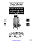
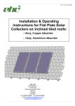
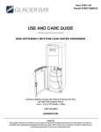
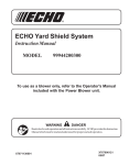
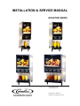
INSTALLATION & SERVICE MANUAL
QUANTUM SERIES
IMI CORNELIUS INC.
www.cornelius.com
Part Number- 720901120
Revision B - November 23, 2004
TABLE OF CONTENTS
UNIT SPECIFICATIONS.................................................................... 1
PREINSTALLATION ...........................................................................2
Receiving ..............................................................................................................2
Unpacking ............................................................................................................. 2
Counter Location .................................................................................................. 2
installation specifications ............................................................... 3
Water Supply ........................................................................................................ 3
Electrical ................................................................................................................3
Space ................................................................................................................... 3
Connecting Water Supply .....................................................................................3
Filling Unit with Water ........................................................................................... 3
Flushing and Sanitizing on Start Up ..................................................................... 4
Programming Portion Control (optional) ...............................................................4
Cancel/Pour Button .............................................................................................. 4
Concentrate loading and brixing .................................................... 5
Placing Concentrate Products on Dispensing Platform........................................ 5
Changing Concentrate Flavor ............................................................................... 5
Pump Priming ....................................................................................................... 5
Brix Setting ........................................................................................................... 5
Cleaning and sanitizing procedures ............................................... 6
Daily: System Flush Procedure ............................................................................
Daily: Part Washing ..............................................................................................
Weekly: Sanitizing Procedure...............................................................................
Weekly: Check Brix Setting ..................................................................................
Semi-Annual: General Cleaning ...........................................................................
Yearly: Replace Pump Tubing..............................................................................
6
6
6
7
7
7
Trouble-shooting guide ................................................................. 11
Quantum Series Installation and Service Manual
UNIT SPECIFICATIONS
Clearance Recommended: 12” (30.48 cm) on top and 4” (10.16 cm) required in back for air circulation if sides are blocked off. If sides are open only 2” (5.08) are required in back. Space between
bottom of unit and counter cannot be obstructed in foot print area.
Electrical Connection: 6ft. long (1.83m) power cord with 3-prong plug attached to dispenser.
Export models have line cord less plug.
Power Supply: 15 amps at 120 volts or 10 amps at 220 volts.
Water Connection: 3/8” (0.95 cm) SAE male flare fitting on dispenser.
Water Supply Requirements: 80 psi (5.5 bar) maximum static pressure. 20 psi (1.4 bar) minimum
dynamic pressure; i.e., flowing pressure measured at dispenser water inlet with 3.0 ounces
(88.7ml) per second water flow.
-1-
720901120
Quantum Series Installation and Service Manual
PREINSTALLATION
RECEIVING
Each unit is completely tested and inspected before shipment. At time of shipment, the carrier
accepts the unit and any claim for damage must be made with the carrier.
Upon receiving from the carrier, please, inspect the carton for visible damage. If damage exists,
have the carrier make a note on the bill of lading and file a claim with the carrier.
UNPACKING
•
•
•
•
•
•
•
Remove staples securing carton to pallet.
Lift carton up and off of unit.
Remove top insert and shipping bag.
Open the upper cabinet door and remove installation kit.
Remove bolts securing unit to pallet.
Lift unit off of pallet.
Open the package, take legs and secure them to the bottom of the unit.
NOTE: Do not lay the unit on sides or on the back.
•
•
Tilt the unit only when securing legs.
If the unit is to be transported from the place where it was unpacked, do not remove the unit
from the pallet. Transport it on the pallet to the installation site.
COUNTER LOCATION
•
Select location in well ventilated area, close to grounded electrical outlet. If possible do not
place the unit close to hot and/or steaming machines.
720901120
-
2-
Quantum Series Installation and Service Manual
INSTALLATION
SPECIFICATIONS
W ATER SUPPLY
The Quantum Juice Dispensing machine is designed to dispense juice at a high flow rate. It is very
important that the incoming water line is dedicated for the unit, or at least does not have other
machines connected which could cause a water surge; i.e., a dishwashing machine.
NOTE: For increased cooling capacity the unit should be connected to a remote
recirculating cooling unit. If the location is equipped with a dedicated beverage water supply system the juice dispenser should be connected to it.
NOTE: The water supply should be consistent with proper water quality standard
(neutral ph of 7.0 to 8.0), and should not be connected to a water softener. The water cooling coil is Copper, and may be affected by poor water conditions (i.e. severe
corrosion and pitting).
Water connections shall be sized, installed, and maintained according to Federal, State, and Local
Laws.
ELECTRICAL
A minimum of 15 amps electrical service is needed for 120V power supply or 10 amps for 220V
supply.
SPACE
The minimum clearance is: 4” (10.16cm) in back and 12” (30.48cm) on top and open to the front if
sides are blocked off. If the sides are open then only 2” (5.08cm) is required in the back. Space
between the bottom of the unit and the counter cannot be obstructed.
NOTE: Condenser air is drawn from the bottom and discharged out the back. Failure to maintain clearance space will reduce capacity of the unit and cause premature compressor failure.
CONNECTING W ATER S UPPLY
1.
Secure 3/8” (0.95cm) flexible hose to the unit water inlet. Make sure that the seal washer is
used (hose and seal washer are included with the installation kit).
2.
When securing flare nut use backup wrench on male side of the fitting (unit side) to prevent
twisting of the copper tube inside the unit and/or possible damage to the water strainer/solenoid. A water shut off outside the unit is recommended.
FILLING U NIT
WITH
W ATER
To properly prime the unit with water, without air pockets in the system, push the dispensing
switches simultaneously for a few seconds each. Repeat above until a steady flow of water is
observed.
NOTE: Water splashing may occur during the purge cycle.
-3-
720901120
Quantum Series Installation and Service Manual
FLUSHING
AND
SANITIZING ON START UP
Follow standard sanitizing and flushing procedure.
PROGRAMMING PORTION CONTROL ( OPTIONAL)
The portion control supplied with your orange juice dispenser has been programmed to pour 7, 12,
and 16 ounce drinks. The “XL” size has also been programmed to pour 16 ounces. Should pour
size adjustments be required, please follow the instructions below:
1.
Simultaneously, press and hold “S” (small) and “XL” (extra large) push button switches on the
Portion Control Module until the led “REFILL” light in the corner of the module starts blinking.
Release the switches. The blinking led indicates the programming mode is active.
2.
Place the cup under the white mixing valve nozzle and push the selected size button (small,
medium, large, or extra large). Hold the button in until the cup fills to the desired portion, then
release the button repeat the above procedure for the remaining sizes.
3.
After programming all the drink sizes, press and release the “cancel/pour” switch to return the
Portion Control to the operational mode. The blinking led light will go out.
If at a future date, it is decided to change the portion size of the drinks, the individual sizes
can be adjusted by the above procedure. It is not necessary to reprogram every size.
The portion control has a full memory retention in case of a power failure.
CANCEL/POUR B UTTON
•
•
Push and release the cancel/pour button to stop the valve from dispensing.
Push and hold for a continuous pour.
720901120
-
4-
Quantum Series Installation and Service Manual
CONCENTRATE
LOADING AND BRIXING
PLACING C ONCENTRATE P RODUCTS
ON
D ISPENSING PLATFORM
To engage the concentrate container, place it in the desired position and press down into bottle
adapter opening on dispensing platform tray (inside the cabinet).
NOTE: Make sure o-ring seal on the container adapter is lubricated; otherwise, you
may experience difficulties with container replacement.
NOTE: Concentrate in the containers must be completely thawed and be within the
temperature range of 35°F - 40°F (1.6°C - 4.4°C). Failing to supply concentrate inside
the recommended temperature range, especially below 35°F (1.6°C), will cause an
out of brix drink.
It is recommended the concentrate be thawed in a refrigerated (35°F - 40°F) (1.6°C - 4.4°C) compartment for 36 to 48 hours before use.
It is recommended that the thawed concentrate be thoroughly shaken before use.
CHANGING CONCENTRATE F LAVOR
1.
Perform flush cycle
2.
Move valve handle to “Dispense” position
3.
Replace concentrate container
PUMP PRIMING
1.
Follow instructions in paragraph “Placing Concentrate Products on the Dispensing Platform”
2.
Close the door (or unit will not activate)
3.
Depress the push button until concentrate appears at the dispensing nozzle.
BRIX SETTING
1.
Make two (2) full clockwise turns of the corresponding brix knob from the “all the way out” position (factory set). These two turns will bring you within one turn of proper brix setting. (Refer
to brix table located on the inside of the refrigerated compartment door).
2.
Dispense 1/2 cup of juice and discard.
3.
Dispense 1/2 cup of juice and use refractometer to check brix level.
4.
Clockwise rotation of the knob decreases brix level for example from 13% to 11.5%. Counterclockwise will increase brix level for example from 11.5% to 13%.
If a brix problem is experienced, refer to troubleshooting guide.
-5-
720901120
Quantum Series Installation and Service Manual
CLEANING AND
SANITIZING
PROCEDURES
DAILY: S YSTEM F LUSH P ROCEDURE
1.
A 1 quart (0.95 liters) (32 fluid oz. minimum) empty container is needed. Place the empty container on the drip tray grill under the nozzle of the dispensing station to be flushed.
2.
Open the cabinet door.
3.
Choose the valve handle that corresponds with dispensing station to be flushed.
4.
Move chosen handle from “dispense” position to the “flush” position.
5.
Close the door.
6.
Depress and hold push button corresponding with dispensing station to be flushed, until clear
water is dispensed from the nozzle.
7.
Move the handle to the “dispense” position.
8.
Depress the push button for approximately 0.5 sec. and release. This will release water pressure from the pump system.
It is recommended to use one or more quarts of water to flush a single dispensing station.
DAILY: P ART W ASHING
1.
Remove and wash dispensing nozzle, static mixer, splash plate, drip pan, bracket, and grille
in a mild detergent solution. Rinse thoroughly.
W EEKLY: S ANITIZING P ROCEDURE
1.
Remove juice concentrate container from unit and place in separate refrigerated compartment.
2.
Perform flush procedure.
3.
Fill a clean empty concentrate container with one quart of extremely hot tap water, approximately 140°F (60°C) and place into unit. Run the hot water completely through unit into a large
container. When complete remove concentrate container.
4.
Remove nozzles and static mixers from unit and rinse under hot tap water to remove excess
pulp.
5.
Place nozzles and static mixers in separate container with 1 quart (0.95 liter) of sanitizing solution and agitate vigorously, using brush (P/N 07932) to remove any excess pulp or concentrate (allow to soak for 2 minutes).
6.
Clean bottle adaptor’s inlet area along with dispensing platform tray with brush and sanitizing
solution to remove concentrate and pulp.
7.
Clean valve mixing chambers with brush and sanitizing solution. (This is the cavity from which
the nozzle is removed).
8.
Replace nozzles and static mixers into proper location.
720901120
-
6-
Quantum Series Installation and Service Manual
9.
Fill a clean empty concentrate container with 2 quarts (1.9 liters) of sanitizing solution, place
on dispensing platform, and insert bottle fitting into bottle adapter.
NOTE: Do not reuse the same sanitizing solution used to clean nozzles, static mixers, etc.
10. Place handle in dispense position and close door.
11. Run dispensing station for 90 seconds then stop; allow sanitizing solution to remain in lines
for 5 minutes.
12. Dispense remaining sanitizing solution (approximately 90 seconds).
13. Replace sanitizing solution container with a concentrate container, and close door.
14. Depress and hold push buttons until juice appears at outlet of dispensing nozzle.
15. Dispense and discard two 8 oz. cups (236.6 ML) of juice.
NOTE: Wipe internal and external surfaces of cabinet with a clean damp cloth.
W EEKLY: C HECK BRIX SETTING
Tools: Hydrometer or Refractometer
1.
Dispense required ounces of juice per brix testing device instructions.
2.
Test concentrate to water ratio of dispensed juice per brix testing device instructions.
3.
Clockwise rotation of knob decreases brix level (i.e. from 13% to 11.5%). Counterclockwise
rotation of knob increases brix level (i.e. from 11.5% to 13%).
NOTE: If brix problem persists, refer to trouble shooting guide.
SEMI-A NNUAL: G ENERAL C LEANING
1.
Remove access port of Y-shaped water solenoid located on water inlet in lower cabinet, clean
stainless steel strainer and reinstall.
2.
Clean condenser fins.
3.
Clean air inlet grille located in base of unit.
4.
Clean lower cabinet interior.
5.
Wipe fan blade clean.
YEARLY: R EPLACE P UMP T UBING
Removal of Platform (see figure 1):
1.
Remove concentrate container from the dispenser and place in a refrigerator.
2.
Remove the product shelf.
3.
Depress the button on the water line quick disconnect and lift the water line away from the
platform.
4.
Unplug the platform electrical connector at the inside rear of the cabinet.
5.
Release the catch at the front of the platform by pulling the tab towards yourself with on finger.
-7-
720901120
Quantum Series Installation and Service Manual
6.
Remove the nozzle and static mixers.
7.
Carefully lift and pull the platform from the dispenser and place it in a clean and well lit area
for service.
Replacement of Pump Hose (see figure 2):
1.
Remove platform as described above in removal of platform instructions.
2.
Remove the two white plastic hose clamps from the pump tube connections. Remove the two
stainless steel concentrate delivery tubes from the hose ends.
3.
Loosen and remove the four thumb screws from the pump body.
4.
Remove the rear half (only) of the pump body to reveal the hose and rollers.
5.
Remove the old hose from the pump body. If the rollers come out with the hose, place in back
into the housing being sure to align the roller assembly shaft keyway to the motor shaft key
so that the two interlock (see figure 3 for step by step pictorial instructions).
6.
Firmly press the new hose into the pump body around the roller assembly, being sure to keep
the protruding ends even with each other. Once the hose is in place, replace the outer half of
the pump body. Hold the tubing in place inside pump housing with one hand, capture the lower
part of the tubing with the outer housing, then proceed to capture the shaft of the roller assembly and push the housing straight onto the pump/motor portion of the assembly. Make sure to
capture the hose within the body and not pinch it between the halves. Do not use any tool
other than your finger tips to manipulate the hose into the housing or damage to the hose will
result.
7.
While holding the pump halves together by hand, reinsert the four thumb screws and tighten
them in a criss-cross pattern until the two halves are pressed together.
8.
Insert the two stainless tubes into the hose ends and fasten them with new clamps using pliers
to tighten the clamps.
Replace platform in unit, reinstall nozzles and static mixers, connect water, install product
shelf and concentrate, and reconnect power to unit.
720901120
-
8-
Quantum Series Installation and Service Manual
-9-
720901120
Quantum Series Installation and Service Manual
720901120
-
10 -
Quantum Series Installation and Service Manual
TROUBLE-SHOOTING
GUIDE
The following pages contain trouble-shooting charts designed to aid an experienced serviceman in
diagnosing any operating problems that may be experienced. In order to gain maximum benefit
from the charts, please note:
1.
Start at the beginning of the chart and supply the appropriate answer to each question.
2.
Do not skip any section, unless instructed to do so. You may miss the solution to your problem.
3.
Evaluate the possible problem causes in the sequence in which they are presented. In general, they began with the most likely and/or easiest to check, and proceed to the less likely
and/or more complicated.
4.
If, after checking all indicated causes, the problem is not resolved, it is recommended that you
try a second time. Evaluate symptoms carefully and modify your answers as necessary.
5.
If you are unable to resolve a problem after several attempts, contact customer service department at (1-800-238-3600) for assistance.
PROBLEM
Totally Inoperative
No cooling
PROBABLE CAUSE
REMEDY
No power to dispenser due
to tripped circuit
breaker.
Reset circuit breaker. Confirm that
breaker is correct size and no
other equipment is operating on
the same circuit. Also confirm
that supply voltage is +10% of
nameplate specifications.
Loose or broken power supply connection inside
dispenser.
Repair connection
Line voltage is not within
+10% of nameplate
specifications causing
compressor overload to
trip
Contact an electrician
Both thermostats in OFF
position
Turn ON thermostats and recalibrate the temperatures to 34 o F
-40 o F (1.1 o C –4.5 o C).
Defective compressor overload or start capacitor
- 11 -
Replace
720901120
Quantum Series Installation and Service Manual
No cooling (con’t)
No water dispensed,
concentrate only.
720901120
Defective start relay located
on upper rear shelf
inside dispenser
There should be line voltage on the
black wire of the relay when
there is line voltage present on
the orange OR yellow wire.
Replace relay if it fails this test.
Compressor starts but
hums and trips overload
Seized or shorted compressor,
replace.
Compressor starts but does
not switch off of start
winding
Relay or compressor is defective.
Test and replace faulty item.
Compressor short cycles on
overload
Excessively high discharge pressure due to restricted condenser or inoperative
condenser fan motor
Refrigerant leak
Repair leak. Evacuate and
recharge system.
No water to dispenser
Restore water
Water supply line inside
refrigerated cabinet disconnected from pump
platform
Reconnect
Water solenoid located on
pump platform clogged
or defective
Disassemble and clean solenoid.
Replace if necessary.
Main water solenoid/
strainer located at base
of dispenser is clogged,
binding or defective
Remove and clean strainer. Confirm 28VDC is present at solenoid during dispense. Confirm
solenoid coil is not open. Disassemble and clean solenoid.
Water supply pressure is
greater than 80 psi (5.5
bar)
Add external regulator and lower
pressure to 50 psi (3.5 bar)
-
12 -
Quantum Series Installation and Service Manual
No water dispensed,
concentrate only
(con’t).
Freeze-up of water coil or
concentrate chamber
Unplug dispenser and allow 2-4
hours to thaw. Water or concentrate thermostat set too low,
recalibrate to 34oF -40 oF (1.1
oC
- 4.5 o C).
Defective water or concentrate
thermostat, replace.
Refrigerant solenoid stuck open
or not closing fully. Evacuate
system, replace solenoid valve
and recharge
No water and no concentrate, refrigeration is
working
No water and no concentrate, refrigeration is
working
Service switch located
under drip tray in OFF
position
Turn on switch
Door switch open
Door switch must be closed in
order to operate pump. Check
switch operation and replace if
necessary
6.25 amp Fuse inside front
electrical box blown
Replace with 6.25 amp, 250VAC
slow blow fuse and test
No output from Transformer
located on rear upper
shelf
Confirm transformer output by
measuring for 26VAC at fuse.
Replace transformer if necessary
Defective voltage regulator
board (VRB) located
inside front electrical
box
Measure across the blue and black
wire located in the upper left
corner of the board. There
should be 28VDC present when
the dispense button is pressed.
Replace VRB if necessary
Defective portion control
board
Disconnect wire harness from rear
of portion control, close door
switch and short the orange
and black wires together on the
harness. If unit dispenses portion control board is defective. If
it does not dispense the voltage
regulator board is defective.
- 13 -
720901120
Quantum Series Installation and Service Manual
No concentrate dispensed, water only
Excessive remnant left
in empty concentrate pouch
Concentrate refill light
comes on prematurely
Concentrate refill light
does not come on at
all
720901120
Dispense tube not fully
engaged into receptacle on concentrate
pouch
Refer to Concentrate Loading section of this manual
Dispense tube disconnected from mixing
chamber
Refer to Concentrate Loading section of this manual
Slide block on pump in
open position
Close and lock the slide block.
Refer to Concentrate Loading
section of this manual
Switch on pump platform in
FLUSH position
Move switch to RUN position
Concentrate too cold, not
properly thawed
Concentrate should be 34o F -40 o F
Defective pump motor
Replace pump motor
Concentrate pouch improperly thawed
Concentrate should be 34o F -40 o F
Concentrate pouch and/or
dispense tube improperly installed
Refer to Concentrate Loading section of this manual
Concentrate pouch improperly thawed
Concentrate should be 34o F -40 o F
Concentrate pouch and/or
dispense tube improperly installed
Refer to concentrate loading section of this manual
Loose wiring
Check wiring connections between
the pump motor and the VRB
board
Bad VRB board
Replace VRB board
Bad pump motor
Replace pump motor
Pump improperly locked or
pump is open
Close and lock Pump
Run/flush switch is in the
FLUSH position
Move switch to the RUN position
-
14 -
(1.1 o C –4.5 o C) prior to loading
(1.1 o C –4.5 o C) prior to loading
(1.1 o C –4.5 o C) prior to loading.
Quantum Series Installation and Service Manual
Concentrate refill light
does not come on at
all (con’t)
Improperly loaded tube
Refer to concentrate loading section of this manual
Bad VRB board
Replace VRB board
Bad portion control
Replace portion control
Incoming water supply too
warm
Optimum performance is achieved
when the dispenser utilizes
water from a pre-cooler
Ambient air too warm
Relocate dispenser
Excessive demand on dispenser
Add water pre-cooler or second
dispenser
Dirty condenser coil
Clean condenser coil
Inoperative condenser fan
Replace condenser fan motor
Defective water thermostat
Replace thermostat
Loss of refrigerant charge
due to leak in system
Repair leak and recharge system
Water continuously drips
from nozzle when in
OFF mode
Main water solenoid at base
of unit or water solenoid
on pump platform not
shutting off tightly
Clean solenoid(s), replace parts as
necessary
No Flush Cycle
Run/Flush switch on pump
platform in Run mode
Move switch to Flush position
Defective Run/Flush switch
on pump platform (concentrate continues to
dispense while in Flush
mode)
Replace Run/Flush switch
Concentrate thermostat is
turned off or not calibrated properly
Calibrate to be 34o F -40 o F (1.1 o C
Concentrate thermostat
defective (stuck open)
Replace thermostat and calibrate
Defective start relay located
on upper rear shelf
inside dispenser
There should be line voltage on the
black wire of the relay when
there is line voltage present on
the orange OR yellow wire.
Replace relay if it fails this test.
Warm Drink
Concentrate warm,
water cold
- 15 -
–4.5 o C)
to 34 o F -40 o F (1.1 o C –4.5 oC)
720901120
Quantum Series Installation and Service Manual
Concentrate warm,
water cold (con’t)
Loss of refrigerant charge
due to leak in system
Repair leak and recharge system
Brix Problem
Water supply pressure too
low, less than 20 psi (1.4
bar) flowing or water
pressure fluctuates
sharply
Correct water supply problem to
ensure a constant 40 psi (3 bar)
flowing to the dispenser
Water flow control binding
or spring is defective
Clean and/or replace parts as necessary
Improperly thawed concentrate. Brix changes as
the concentrate temperature changes (concentrate becomes thinner
as temperature rises)
Concentrate should 34 o F -40 o F
Check that the rollers on the
pump are spinning
freely with no tube in
place
If they are sticky or locked up see
platform removal and cleaning
procedure.
Pump motor defective
28VDC should be present at pump
motor during dispense. If voltage is present and motor does
not start, replace pump motor
No power to transformer or
no 28VAC output from
transformer
Confirm transformer has line voltage present on primary side. If
no 28VAC output from the secondary replace transformer
Defective voltage regulator
board (VRB) located
inside front electrical
box
Measure across the blue and black
wire located in the upper left
corner of the board. There
should be 28VDC present when
the dispense button is pressed.
Replace VRB if necessary
Defective portion control
board
Disconnect wire harness from rear
of portion control, close door
switch and short the orange
and black wires together on the
harness. If unit dispenses portion control board is defective. If
it does not dispense the voltage
regulator board is defective.
Pump Inoperative
720901120
-
16 -
(1.1 o C –4.5 o C) prior to loading
Quantum Series Installation and Service Manual
Machine continues to
dispense after dispense button is
released or dispenses without
operator input
Sold Out light illuminates when concentrate no longer
passes through the
pump.
Portion control pad stuck in
on position
Disconnect the wire harness from
the rear of the portion control
and close the door. If unit does
not dispense on its own the portion control is bad (stuck on)
Relay on voltage regulator
board (VRB) stuck on.
Disconnect the 4-wire harness
from the lower right corner of
the VRB. If the unit continues to
dispense on its own the VRB is
defective (relay stuck on)
The concentrate is improperly thawed. The temperature is not
maintained between
34×F - 40×F(1.1-4.5×C)
Assure proper thawing procedures
have been followed per the
Minute Maid company instructions.
Check that McDonald’s walk-in
cooler temperature is on the
proper set point.
Check the dispenser cabinet temperature is at 34×F - 40×F(1.14.5×C).
High Brix readings result in
a poor, pulsating/splashing dispense, erratic
pump amp draw, and
consequently erratic
sold-out indications.
- 17 -
Check drink brix in procedure
described on equipment P.M.
card using the hydrometer provided.
Check the drink flow rate under
normal operating conditions.
The dispenser should pour a
drink at a flow rate of approximately 1.5 oz. Per second or
greater. If the flow rate is less, a
check described in the Sold Out
section should be completed.
720901120
Quantum Series Installation and Service Manual
Sold Out light illuminates when concentrate no longer
passes through the
pump.(con’t)
Improper loading procedures will usually result
in low brix conditions
and thus erratic sold out
indications.
Check that the pouch of juice is
properly loaded in the pouch
holder. Tube fitting should be
located at the bottom of the
pouch holder and the tube
should be approximately centered in the bottom portion of
the opening of the holder.
Check that the tube is correctly
loaded in the pump and the
pump is fully locked (top and
bottom slide pins should be
fully engaged into the pump
body).
Sold Out light fails to
reset itself after door
is opened and
closed (Sold Out
light stays illuminated)
720901120
Tube has been stretched
through pump when it
was loaded. Pouch may
not be seated correctly.
Adjust pouch. If pouch is loaded
correctly there should be ample
tube to reach the mixing chambers without stretching the
tube.
Check that the rollers on the
pump are spinning
freely with no tube in
place.
If the rollers are sticky or locked up
see the platform removal and
cleaning procedure.
Check the operation of the
reset switch located at
the bottom left hand
side of the door.
Adjust Switch.
-
18 -
IMI Cornelius Inc.
One Cornelius Place
Anoka, MN 55303-1592
U.S.A.
Total Systems Commitment