1
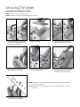
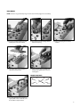
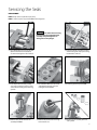
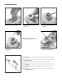
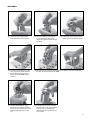
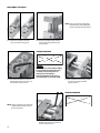
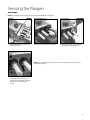
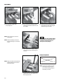
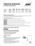
SERVICE MANUAL
1570 PLUNGER PUMP
PUMP
MODEL
1570
FLOW
gpm
lpm
6.0
22.7
PRESSURE
psi
bar
6,000
414
RPM
Pump Motor
1350
—
TEMPERATURE
˚F
˚C
120
48
SHAFT DIA.
in
mm
1.181
30
OIL CAPACITY
oz
l
42
1.26
IMPORTANT SAFETY INSTRUCTIONS
It is the responsibility of the user to read and understand all instructions, important safeguards, and safety precautions before operating or
servicing any pump. Failure to do so may result in property damage, personal injury or death.
General Safety Information and Symbols
Pay special attention to the following signal words, safety alert symbols and statements:
DANGER
indicates a hazardous situation which, if not avoided, will result in death or serious injury.
WARNING indicates a hazardous situation which, if not avoided, could result in death or serious injury.
CAUTION indicates a hazardous situation which, if not avoided, could result in minor or moderate injury or property damage.
NOTICE
indicates a hazardous situation which, if not avoided, could result in property damage.
Indicates a potential personal injury hazard. Obey all safety messages that follow this symbol to avoid possible injury or death.
SERVICING THE 1570 PLUNGER PUMP SERIES
WARNING
Do not service pump or electrical equipment while energized.
Electricity can cause personal injury, death or property damage.
1.
2.
3.
4.
Adhere to “Lock Out” and “Tag Out” procedures for electrical equipment.
Before commencing pump service, turn power supply off.
Keep water away from electrical outlets and electrical devices.
Electrical components must be installed by a qualified
electrician to avoid risk of electrocution.
Servicing the Valves
DISASSEMBLY (DISCHARGE VALVES ONLY)
NOTE: One (1) valve kit is required to repair pump.
NOTE: The discharge seat has a smaller diameter than the inlet seat.
1.0 Use a M10 Allen Wrench to remove the
eight (8) Hex Socket Head (HSH) screws
from valve cover on IMDM.
1.1 Remove valve cover.
1.2 U
se a flat tip screwdriver to remove
valve plugs from each valve chamber.
1.3 U
se a pick tool to remove backup-ring
and o-ring from each valve plug.
1.4 R
emove coil spring and then washer
from each valve chamber.
1.5 U
se a needle nose pliers to grab the tip
end of the spring retainer and pull valve
assembly from each valve chamber.
NOTE: Examine seats, valves and springs for grooves, pitting or wear and replace with a
new valve kit as needed.
NOTE: Examine o-rings and backup-rings for cuts or wear and replace with a new valve kit
as needed.
1.6 D
isassemble discharge valve assembly
and inspect all parts per NOTES
2
REASSEMBLY
NOTE: Lubricate o-rings and backup-rings on valve seats and valve plugs prior to reassembly.
1.7 Place new assemblied discharge valve
assembly into each valve chamber.
1.8 P
lace washer over tip of spring retainer
and then coil spring.
1.10 Place valve cover on top of IMDM and
align with threaded holes.
1.11 A
pply anti-sieze lubricant (PN 6119) to
threads of all eight (8) HSH screws and
hand tighten.
1.9 Press in valve plug into each valve
chamber.
TORQUE SEQUENCE
7
1
4
6
5
3
2
8
1.12 Use a M10 Allen Wrench to torque all
eight (8) HSH screws to 398 in lbs, 33 ft
lbs or 45 Nm in sequence show.
3
Servicing the Valves
DISASSEMBLY (INLET VALVES ONLY)
NOTE: One (1) valve kit is required to repair pump.
NOTE: In order to remove inlet valve assembly, remove IMDM and housing block.
NOTICE
Exercise extreme caution when
removing head assembly. The weight of
the head assembly or any twisting action
can damage the ceramic plungers.
2.0 U
se a M8 Allen Wrench to remove the four
(4) Hex Socket Head Screws (HSH) that
secure the housing block to the crankcase.
2.1 P
ostion two flat tip screwdrivers on
either side of housing block and pry the
housing block from the crankcase.
2.2 Pull complete head assembly carefully
over ceramic plungers and place on a
flat surface with the housing block side
facing upwards.
2.3 Use a M10 Allen Wrench to remove the
eight (8) HSH screws that secure the
housing block to the IMDM.
2.4 P
ull housing block away from IMDM.
2.5 Remove outer cylinders with seal case
assembly from IMDM.
2.6 R
emove V-Packing (V/P) cylinder
assembly from each IMDM valve
chamber.
2.7 Use a reverse pliers to grasp spring
retainer and pull inlet valve assembly
from each valve chamber.
4
NOTE: Examine seats, valves and springs for grooves, pitting or wear and replace with a
new valve kit as needed.
NOTE: Examine o-rings and backup-rings for cuts or wear and replace with a new valve kit
as needed.
2.8 Disassemble inlet valve assembly and
inspect all parts per NOTES
REASSEMBLY
NOTE: Lubricate o-rings and backup-rings on valve seats and V/P cylinders and o-rings on outer cylinder prior to reassembly.
2.9 Place new assembled inlet valve
assembly into each valve chamber.
2.10 Position V/P cylinder assembly into
IMDM and hand press into place.
2.11 S lide outer cylinder with seal case
assembly and hand press into place.
NOTE: Apply anti-sieze lubricant (PN 6119) to threaded ends of all eight (8) HSH screws and hand
thread into position.
2.12 P
osition housing block with counterbore surfaces facing downward over
outer cylinders.
5
REASSEMBLY CONTINUED
TORQUE SEQUENCE
7
1
4
6
5
3
2
8
NOTICE
Exercise extreme caution when installing
head assembly. The weight of the head
assembly or any twisting action can
damage the ceramic plungers.
Rotate crankshaft by hand so the two
outside plungers are extended equally.
2.13 U
se a M10 Allen Wrench to torque all
eight (8) HSH screws to 398 in lbs, 33 ft
lbs or 45 Nm in sequence show.
2.14 S lide complete head assembly carefully
over ceramic plungers until flush against
crankcase.
TORQUE SEQUENCE
NOTE: A
pply Loctite®242® to threaded ends
of all four (4) HSH screws and hand
thread into position.
2.15 U
se a M8 Allen Wrench to torque all four
(4) HSH screws to 531 in lbs, 44 ft lbs or
60 Nm in sequence show.
Loctite and 242 are registered trademarks of the Henkle Corporation
6
4
1
2
3
Servicing the Seals
DISASSEMBLY
NOTE: One (1) seal kit is required to repair pump.
NOTE: In order to replace seals, remove IMDM and housing block.
NOTICE
Exercise extreme caution when removing
head assembly. The weight of the head
assembly or any twisting action can
damage the ceramic plungers.
3.0 U
se a M8 Allen Wrench to remove the four
(4) Hex Socket Head Screws (HSH) that
secure the housing block to the crankcase.
3.1 P
ostion two flat tip screwdrivers on either
side of housing block and pry the housing
block from the crankcase.
3.2 Pull complete head assembly carefully
over ceramic plungers and place on a flat
surface with the housing block side facing
upwards.
3.3 Use a M10 Allen Wrench to remove the
eight (8) HSH screws that secure the
housing block to the IMDM.
3.4 Pull housing block away from IMDM.
3.5 Remove outer cylinder with seal case
assembly from IMDM.
3.6 Remove low pressure seals and o-rings
from each seal case.
3.7 R
emove seal case assembly from each
outer cylinder.
7
DISASSEMBLY CONTINUED
3.8 Remove V/P cylinders from IMDM.
3.9 R
emove female adapter from each
V/P cylinder.
3.10 R
emove v-packings (qty 3) from each
V/P cylinder.
NOTE: R
emove o-ring and backup-rings
from each V/P cylinder.
3.11 R
emove male adapter from each
V/P cylinder.
3.12 R
emove collars and wicks from
crankcase side of housing block.
NOTE: Examine low pressure seals and v-packings for wear and replace with a new seal kit
as needed.
NOTE: Examine o-rings, backup-rings and wicks for cuts or wear and replace with a new
seal kit as needed.
NOTE: Examine collars for wear or damage and replace individually as needed.
NOTE: Examine female adapters for grooves, pitting or wear and replace with a new seal kit
as needed.
NOTE: Examine male adapters for grooves, pitting or wear and replace individually
as needed.
NOTE: Examine seal case, outer cylinder and V/P cylinders for wear or damage and replace
individually as needed.
3.13 Inspect all parts per NOTES
8
REASSEMBLY
3.14 Install brass male adapter with flat
surface down into each V/P cylinder.
3.15 Lubricate and install v-packings with
v-grooved side down into each V/P
cylinder. Each cylinder requires three (3)
v-packings.
3.16 Install female adapter with v-grooved
side facing down into each V/P cylinder. 3.17 Lubricate and install backup-ring and
then o-ring onto small end of each V/P
cylinder. Position small end of each
V/P cylinder into the IMDM and press
into place.
3.18 L ubricate and install o-ring into groove of each outer cylinder. Slide outer cylinder over
each V/P cylinder and hand press into IMDM.
3.19 L ubricate outside diameter of each
low pressure seal and inside diameter
of each seal case. Install low pressue seal
with spring side down into each seal
case.
3.20 Lubricate seal case o-ring and inside
diameter of each outer cylinder. Hand
press each seal case assembly with
low pressure seal facing outwards into
outer cylinder.
9
REASSEMBLY CONTINUED
NOTE: A
pply anti-sieze lubricant (PN 6119)
to threaded ends of all eight (8) HSH
screws and hand thread into position.
3.21 Install wicks and then collars into
crankcase side of housing block.
3.22 P
osition housing block with counterbore surfaces facing downward over
outer cylinders.
TORQUE SEQUENCE
7
1
4
6
5
3
2
8
NOTICE
Exercise extreme caution when installing
head assembly. The weight of the head
assembly or any twisting action can
damage the ceramic plungers.
Rotate crankshaft by hand so the two
outside plungers are extended equally.
3.23 Use a M10 Allen Wrench to torque all
eight (8) HSH screws to 398 in lbs, 33 ft
lbs or 45 Nm in sequence show.
3.24 S lide complete head assembly carefully
over ceramic plungers until flush
against crankcase.
TORQUE SEQUENCE
NOTE: A
pply Loctite®242® to threaded ends
of all four (4) HSH screws and hand
thread into position.
3.25 Use a M8 Allen Wrench to torque all four
(4) HSH screws to 531 in lbs, 44 ft lbs or
60 Nm in sequence show.
10
4
1
2
3
Servicing the Plungers
DISASSEMBLY
NOTE: Servicing the plungers must be done by removing the IMDM and housing block.
4.0 Remove IMDM and housing block as a
complete assembly.
4.1 R
emove seal retainers from crankcase.
4.2 U
se a 7/8" wrench to remove plunger
assembly from each plunger rod.
NOTE: Inspect all three (3) plunger assemblies for cracks, pitting and scoring and replace
individually as needed.
4.3 Inspect all three (3) crankcase oil seals
and plunger rods for damage or oil
leakage. Contact Cat Pumps for proper
instructions on removal of these
oil seals.
11
REASSEMBLY
4.4 Install plunger assembly onto
each plunger rod.
4.5 U
se a 7/8" wrench to torque the three
(3) plunger assemblies to 398 in lbs, 33 ft
lbs or 45 Nm.
NOTE: A
pply a light grease to the end
each plunger.
4.6 Install seal retainers with slot opening
facing upwards and the small stepped
diameter facing the manifold.
NOTICE
Exercise extreme caution when installing
head assembly. The weight of the head
assembly or any twisting action can
damage the ceramic plungers.
NOTE: Rotate crankshaft by hand so the
two outside plungers are extended
equally.
4.7 Slide complete head assembly carefully
over ceramic plungers until flush against
crankcase.
TORQUE SEQUENCE
NOTE: Apply Loctite®242® to threaded ends
of all four (4) HSH screws and hand
thread into position.
4
1
2
3
NOTE: Visually inspect bubble oil gauge,
drain plug, bearing covers and
rear cover for oil leakage. Replace
individually as needed.
4.8 U
se a M8 Allen Wrench to torque all four
(4) HSH screws to 531 in lbs, 44 ft lbs or 60
Nm in sequence show.
12
Safety
IMPORTANT SAFETY
INSTRUCTIONS
It is the responsibility of the user to read
and understand all instructions, important
safeguards, and safety precautions before
operating or servicing any pump. Failure
to do so may result in property damage,
personal injury or death.
GENERAL SAFETY
INFORMATION AND SYMBOLS
Pay special attention to the following signal
words, safety alert symbols and statements:
Indicates a hazardous situation which,
if not avoided, will result in death or
serious injury.
Safety Hazards
A. FLAMMABLE OR EXPLOSIVE LIQUID HAZARD
Do not operate pump with flammable or explosive liquids
unless extraordinary safety precautions are observed. Leaks
of flammable or explosive liquids, if exposed to elevated
temperatures, static electricity, sparks or other hazards, will
result in flame or possible explosion, causing serious personal
injury, death or property damage.
1. Before operating pump with flammable or explosive liquids, ensure
proper maintenance has been performed.
2. D
o not operate pump with flammable or explosive liquids if leaks
are detected.
3. O
nly pump flammable or explosive liquids that are compatible with
pump component materials.
4. Do not operate pump with flammable or explosive liquids without
safeguards or safety systems to detect leaks, elevated temperatures,
spark prevention or any other hazards defined by the NFPA systems.
5. Do not remove Flammable Liquids Product Suitability Hang Tag to
assure proper safety.
6. Follow ATEX guidelines for potentially explosive atmospheres.
A. ELECTRICAL SHOCK HAZARD
Indicates a hazardous situation which,
if not avoided, could result in minor or
moderate injury or property damage.
Indicates a hazardous situation which,
if not avoided, could result in death or
serious injury.
Indicates a hazardous situation which,
if not avoided, could result in property
damage.
Indicates a potential personal injury
hazard. Obey all safety messages
that follow this symbol to avoid
possible injury or death.
Do not service pump or electrical equipment while energized.
Electricity can cause personal injury,
death or property damage.
1. Adhere to “Lock Out” and “Tag Out” procedures for electrical
equipment.
2. Before commencing pump service, turn power supply off.
3. Keep water away from electrical outlets and electrical devices.
4. Electrical components must be installed by a qualified electrician to
avoid risk of electrocution.
B. ROTATING PARTS HAZARD
Do not service pump while energized. Moving, rotating or
reciprocating parts can crush and cut, causing personal injury,
death or property damage.
1. Adhere to “Lock Out” and “Tag Out” procedures for electrical
equipment.
2. B
efore commencing pump service, turn power supply off, turn
water supply off, squeeze trigger on gun to relieve system pressure.
3. F or mobile equipment, be sure engines and hydraulics are turned
off and secured to avoid accidental start.
4. Do not operate with safety guards removed.
5. Always use safety guards on all belt drives, couplings and shafts.
C. HOT SURFACE HAZARD
Do not touch pump, accessories or drive system while operating
and until cool down is complete. Touching hot surface areas of
the pump, accessories or drive system can cause severe burns or
personal injury.
D. SKIN PUNCTURE HAZARD
Do not allow spray to contact any part of the body or animals.
Pumped liquids under high pressure can pierce skin and
underlying tissue or can deflect debris leading to serious
personal injury or death.
1. Relieve all line pressure in the inlet line to the pump and discharge
line from the pump before performing any maintenance on the
pump.
13
Continued
2. W
hen high pressure gun is not in use, set safety trigger lock (safety latch) to avoid accidental high pressure operation
and personal injury or property damage.
3. D
o not check for leaks with hand. Use a piece of cardboard to check for leaks.
4. Review cleaning procedures to minimize heavy back blasting.
5. Wear adequate safety equipment and clothing when operating high pressure sprayer. Never use high pressure spray
with bare feet or exposed skin, and always wear safety glasses.
E. PUMPING LIQUIDS HAZARD
Do not operate pump with hot water, chemicals, or other hazardous liquids unless extraordinary safety
precautions are observed. Pumping hot water, chemicals, or other hazardous liquids can expose personnel to
serious injury.
1. Provide guards or shields around equipment to protect personnel.
2. W
ear mask, goggles or eye protection while operating high pressure equipment.
3. O
btain a material safety data sheet (MSDS) and take appropriate safety measures for the liquid being handled.
F. OVER PRESSURIZATION HAZARD
Do not operate high pressure pumping system unless extraordinary safety precautions are observed. A high
pressure pumping system can deadhead or over pressurize causing serious personal injury and property damage.
1. All high pressure systems require a primary pressure regulating device (i.e., regulator or unloader) and a secondary
pressure safety relief device (i.e., pop-off valve, safety valve, rupture disc) to assure proper pressure setting and
overpressure protection.
2. A
ll high pressure systems require a pressure gauge to monitor pressure settings and avoid overpressure of equipment
or personal harm.
3. Install primary pressure relief device on the discharge side of the pump.
4. Install secondary pressure relief device between the primary device and pump.
5. Install pressure gauge onto the discharge manifold or in the discharge line near the manifold.
6. Open all valves on discharge side of plumbing before operation.
G. OXYGEN HAZARD
Do not charge Prrrrr-O-Lators (Pulsation Dampeners) with oxygen. Oxygen may cause an explosion causing
personal injury, death or property damage.
1. Use nitrogen only when charging pulsation dampeners, DO NOT USE OXYGEN.
2. Use proper charging tools to charge pulsation dampeners.
3. C
harge pulsation dampener within specifications stated on data sheet to assure proper pulsation dampening and
prevent failure of bladder.
H. FALL HAZARD
Do not operate pressure washer while standing on slippery or unstable surface unless extraordinary safety
precautions are observed. Pressure washing may create slippery surface on which a person may slip and fall
causing personal injury or death.
1. Wear suitable footwear to maintain a good grip on wet surfaces.
2. Do not stand on ladders or scaffolding.
3. Do not over reach or stand on unstable supports.
4. Keep good footing and balance and hold gun with both hands to control kick back.
A. IMPROPER USE OF FITTINGS HAZARD
Do not operate the pump with improperly connected, sized, worn or loose fittings, pipes or hoses. Operating
the pump under these conditions could result in personal injury and property damage.
1. Ensure all fittings, pipes and hoses are properly rated for the maximum pressure rating and flow of the pump.
2. Check all fittings and pipes for cracks or damaged threads.
3. C
heck all hoses for cuts, wear, leaks, kinks or collapse before each use.
4. Ensure all connections are tight and secure.
5. Use PTFE thread tape or pipe thread sealant (sparingly) to reconnect plumbing. Do not wrap tape beyond the last
thread, this will prevent tape from becoming lodged in the pump or accessories.
6. Apply proper sealants to assure secure fit or easy disassembly when servicing.
B. FROZEN LIQUID HAZARD
Do not operate the pump with frozen liquid. Operating the pump under this condition could over pressurize
and jettison the manifold from the crankcase causing personal injury and property damage.
1. Store pump or pumping system in an environmentally controlled room protected from freezing temperatures.
2. Follow procedures in TECH BULLETIN 083 to winterize pump.
14
C. CLEANING PUMP HAZARD
Continued
Do not use solvents that are flammable and toxic to clean or degrease equipment. Use of these solvents could
result in personal injury and property damage.
1. Follow safety instructions as found in MSDS or on packaging of each liquid.
2. Clean equipment in a well ventilated area.
3. D
isposal of solvents to be in accordance with local, state and federal regulations.
D. OPERATING BEYOND SPECIFICATIONS HAZARD
Do not operate the pump outside the specifications of individual pump data sheet or service manual. Operating
the pump under these conditions could result in personal injury and property damage.
1. Do not operate the pump faster than the maximum recommended RPM.
2. D
o not operate the pump at pressures higher than the maximum
recommended pressure.
3. D
o not operate the pump at temperatures higher than the maximum recommended temperatures.
4. Do not use accessories that are not compatible or rated for the pump.
E. LIFTING DEVICE HAZARD
Do not lift pump with unsuitable lifting devices. Use of unsuitable lifting devices may cause pump to fall
resulting in personal injury, damage to pump and/or pump with drive/base plate.
1. Lifting eyes installed on the pump must be used only to lift the pump.
2. S pecial lifting eyes should be installed on the base for lifting the pumping system (i.e. base, drive and accessories)
3. If slings or chains are used for lifting, they must be safely and securely attached to properly balance the weight
of the unit.
4. Inspect slings and chains prior to use and replace worn and damaged slings and chains.
A. ROTATION OF PUMP HAZARD
Do not rotate pump crankshaft in reverse direction. Rotation of pump crankshaft in reverse direction may not
provide proper lubrication and may result in damage to the drive-end components.
1. Forward rotation is the top of the crankshaft turning towards the manifold head of the pump.
2. E nsure oil is filled to the center red dot on sight gauge for forward rotation.
3. E nsure oil is filled to slightly above center red dot on sight gauge for reverse rotation.
B. BELT TENSION HAZARD
Do not operate pump with excessive belt tension. Excessive belt tension may damage the pumps bearings or
reduce horsepower.
1. Rotate pump crankshaft before starting to ensure shaft and bearings are moving freely.
2. Ensure pulleys are properly sized.
3. Periodically replace belts to assure full horsepower transmission.
4. Ensure center distance dimensions between pulleys is correct.
C. BY-PASS OPERATION HAZARD
Do not operate the pump in by-pass for extended lengths of time. Operating the pump under this condition can
quickly cause heat build-up resulting in damage to the pump.
1. Route by-pass line to supply reservoir to dissipate heated by-pass liquid into a large reservoir of cool water to reduce
excessive temperature build-up.
2. R
oute by-pass line to inlet of pump using a thermo valve in the by-pass line or auto shut-off assembly that will sense
temperature rise and either by-pass or shut down system before damage occurs.
D. DRY OPERATION HAZARD
Do not operate the pump without water or liquid. Operating pump under these conditions could result in
damage to the pump.
1. Open all valves on inlet side of pump before starting operation to prevent starving the pump.
2. D
o not exceed inlet suction pressure limit specified in pump Data Sheet.
3. E nsure inlet feed exceeds the maximum flow being delivered by the pump.
4. Ensure all fittings, pipes and hoses are properly sized for the pump to avoid restricted flow.
5. Review and implement all other recommendations appropriate for your system from the Inlet Condition Check-List.
15
DIAGNOSIS AND MAINTENANCE
One of the most important steps in a high pressure system is to establish a regular maintenance program. This will vary slightly with each system
and is determined by various elements such as the duty cycle, the liquid being pumped, the actual specifications vs rated specifications of the
pump, the ambient conditions, the inlet conditions and the accessories in the system. A careful review of the necessary inlet conditions and
protection devices required before the system is installed will eliminate many potential problems. Cat Pumps are very easy pumps to service and
require far less frequent service than most pumps. Typically, only common tools are required, making in-field service convenient, however, there are
a few custom tools, special to certain models, that do simplify the process. This service manual is designed to assist you with the disassembly and
reassembly of your pump. The following guide will assist in determining the cause and remedy to various operating conditions. You can also review
our FAQ or SERVICE sections on our WEB SITE for more facts or contact Cat Pumps directly.
PROBLEM
PROBABLE CAUSE
SOLUTION
Low pressure
• Worn nozzle.
• Air leak in inlet plumbing.
•P
ressure gauge inoperative or not registering
accurately.
• Relief valve stuck, partially plugged or improperly
adjusted.
• Inlet suction strainer (filter) clogged or
improperly sized.
• Abrasives in pumped liquid.
• Leaky discharge hose.
• Inadequate liquid supply.
• Severe cavitation.
• Worn seals.
• Worn or dirty inlet/discharge valves.
• Replace with proper size nozzle.
• Tighten fittings and hoses. Use PTFE liquid or tape.
• Check with new gauge. Replace worn or
damaged gauge.
• Clean/adjust relief valve. Replace worn seats/valves
and o-rings.
• Clean filter. Use adequate size filter. Check more
frequently.
• Install proper filter.
• Replace discharge hose with proper rating for system.
• Pressurize inlet.
• Check inlet conditions.
• Install new seal kit. Increase frequency of service.
• Clean inlet/discharge valves or install new valve kit.
Pulsation
Water leak
• Under the manifold
• Into the crankcase
• Foreign material trapped in inlet/discharge valves.
• Clean inlet/discharge valves or install new valve kit.
• Worn V-Packings or Lo-Pressure Seals.
•H
umid air condensing into water inside the crankcase.
• Excessive wear to V-Packings and Lo-Pressure seals.
• Install new seal kit. Increase frequency of service.
• Install new oil cap protector. Change oil every 3 months
or 500 hours.
• Install new seal kit. Increase frequency of service.
Knocking noise
• Inlet supply
• Bearing
• Inadequate inlet liquid supply.
• Broken or worn bearing.
• Check liquid supply. Increase line size or pressurize.
• Replace bearing.
Oil leak
• Crankcase oil seal
• Crankshaft oil seal and o-ring
• Drain plug
• Bubble oil gauge
• Bearing cover
• Filler cap
• Worn crankcase oil seal.
• Worn crankshaft oil seal or o-ring on bearing cover.
• Loose drain plug or worn drain plug o-ring.
• Loose bubble oil gauge or worn bubble oil gauge gasket
• Loose bearing cover or worn bearing cover o-ring.
• Loose filler cap or excessive oil in crankcase.
• Replace crankcase oil seal.
•R
emove bearing cover and replace o-ring and/or oil seal.
• Tighten drain plug or replace o-ring.
• Tighten bubble oil guage or replace gasket.
• Tighten bearing cover or replace o-ring.
• T ighten filler cap. Fill crankcase to specified capacity.
Pump runs extremely rough
• Inlet conditions
• Pump valves
• Pump seals
• Restricted inlet or air entering the inlet plumbing
• Stuck inlet/discharge valves.
• Leaking V-Packings or Lo-Pressure seals.
• Correct inlet size plumbing. Check for air tight seal.
• Clean out foreign material or install new valve kit.
• Install new seal kit. Increase frequency of service.
• Scored plunger.
• Over pressure to inlet manifold.
• Abrasive material in the liquid being pumped.
• Excessive pressure and/or temperature of
pumped liquid.
• Running pump dry.
• Starving pump of adequate liquid.
• Eroded manifold.
• Replace plunger.
• Reduce inlet pressure per specifications.
• Install proper filtration at pump inlet and clean regularly.
• Check pressure and inlet liquid temperature.
Premature seal failure
• DO NOT RUN PUMP WITHOUT LIQUID.
• Increase hose one size larger than inlet port size.
• Replace manifold. Check liquid compatibility.
CAT PUMPS
1681 - 94TH LANE N.E. MINNEAPOLIS, MN 55449-4324
PHONE (763) 780-5440 — FAX (763) 780-2958
e-mail: [email protected]
www.catpumps.com
For International Inquiries go to www.catpumps.com and navigate to the “Contact Us” link.
PN 31381 Rev A 1/15