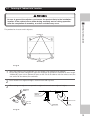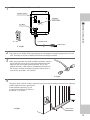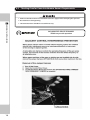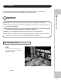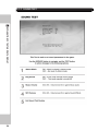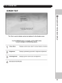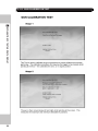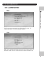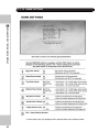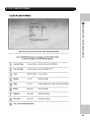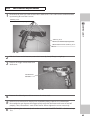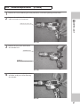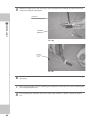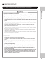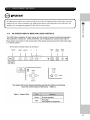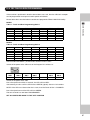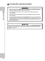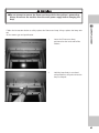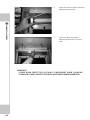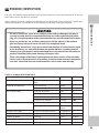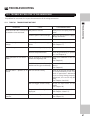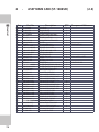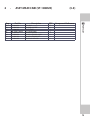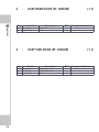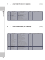
1
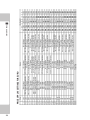
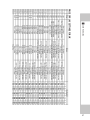
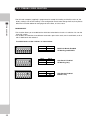
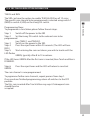
420-0003-01UK
1ST PRINTING
SERVICE MANUAL
SEGA AMUSEMENTS EUROPE LTD.
42 Barwell Business Park, Leatherhead Road,
Chessington, SURREY. United Kingdom KT9 2NY
IMPORTANT
• Before using this product, read this manual carefully to understand the
contents herein stated.
• After reading this manual, be sure to keep it near the product or in a
convenient place for easy reference when necessary.
TABLE OF CONTENTS
BEFORE USING THIS PRODUCT, BE SURE TO READ THE FOLLOWING:
INTRODUCTION..................................................................................................... iv
1 HANDLING AND PRECAUTIONS.................................................................... 1
TABLE OF CONTENTS
TABLE OF CONTENTS.............................................................................................. i
2 PRECAUTIONS REGARDING INSTALLATION LOCATION............................... 4
3 PRECAUTIONS REGARDING PRODUCT OPERATION.................................... 6
4 PART DESCRIPTIONS..................................................................................... 9
5 ACCESSORIES............................................................................................... 10
6 ASSEMBLY AND INSTALLATION.................................................................. 11
6-1 Securing the cabinet in to location ..................................................................................13
6-2 Conneection of Power and Ground...................................................................................14
6-3 Check area for Game Interference Requirements..........................................................16
6-4 Prize Unit (Installation of prizes)........................................................................................17
7 PRECAUTIONS WHEN MOVING THE MACHINE.......................................... 19
8 GAME DESCRIPTION.................................................................................... 20
8-1 HOW TO PLAY.........................................................................................................................20
8-2 IMDIVIDUAL GAME SCREENS..............................................................................................23
8-3 RESULT / ACCURACY SCREEN..............................................................................................25
E0-0704
420-6992UK
9 EXPLANATION OF TEST AND DATA DISPLAY............................................. 26
TABLE OF CONTENTS
9-1 GAME TEST MODE.................................................................................................................27
9-1-1 TEST MENU ...............................................................................................................28
9-1-2 GAME TEST MODE....................................................................................................29
9-1-3 INPUT TEST................................................................................................................30
9-1-4 OUTPUT TEST............................................................................................................31
9-1-5 VENT TEST.................................................................................................................32
9-1-6 COIN TEST..................................................................................................................33
9-1-7 SOUND TEST..............................................................................................................34
9-1-8 SCREEN TEST.............................................................................................................35
9-1-9 GUN CALIBRATION TEST.........................................................................................36
9-1-10 BOOK-KEEPPING......................................................................................................38
9-1-11 GAME SETTINGS.......................................................................................................42
9-1-12 CLOCK SETTINGS......................................................................................................43
10 CONTROLLER (GUN UNIT).......................................................................... 44
10-1 MICROSWITCH REPLACEMENT.........................................................................................45
10-2 SENSOR UNIT RELPACEMENT...........................................................................................46
10-3 SOLINOID REPLACEMENT (if fitted).................................................................................47
11 GRAPHICS DISPLAY..................................................................................... 49
11-1 SAFETY PRECAUTIONS WHEN HANDLING THE DISPLAY.............................................49
11-2 CLEANING THE SCREEN SURFACE....................................................................................50
11-3 ADJUSTMENT METHOD.....................................................................................................51
12 COIN SELECOR AND CREDIT SETTINGS....................................................... 53
12-1 CLEANING THE COIN SELECTOR.......................................................................................53
12-2 CREDIT SETTINGS UK/EURO..............................................................................................55
12-3 STERLING / EURO SELECTION...........................................................................................58
12-4 SR3 TEACH AND RUN INFORMATION..............................................................................59
13 REPLACING THE FLUORESCENT LAMPS..................................................... 62
14 PERIODIC INSPECTION................................................................................ 65
15 TROUBLESHOOTING.................................................................................... 67
16 GAME BOARD.............................................................................................. 68
17 DESIGN RELATED PARTS............................................................................. 70
18 PARTS LIST................................................................................................... 71
19 WIRE COLOUR CODE TABLE........................................................................ 85
20 WIRING DIAGRAMS..................................................................................... 86
ii
INTRODUCTION
This manual is intended to provide detailed descriptions together with all the necessary information
covering the general operation of electronic assemblies, electro-mechanicals, servicing control, spare
parts, etc. for the product, “MANIC PANIC GHOSTS.”
INTRODUCTION
This manual is intended for the owners, personnel and managers in charge of operation of the product.
Operate the product after carefully reading and sufficiently understanding the instructions.
In the unlikely event that the product does not function correctly, DO NOT allow anyone other than
a technician to touch the internal system. Turn off the power to the machine, making sure to unplug
the electrical cord from the outlet, and contact the office listed below or the point of purchase for this
product.
Use of this product is unlikely to cause physical injuries or damage to property. However, points that
require special attention are indicated by bold text, the word “IMPORTANT” and the symbol below.
Indicates important information that, if ignored, may result in the mishandling of the
product and cause faulty operation or damage to the product.
SEGA AMUSEMENTS EUROPE, LTD.
Block C, 42 Barwell Business Park, Chessington, Surrey. KT9 2NY United Kingdom.
Telephone: +44 (0) 208 391 8090 Facsimile: +44 (0) 208 391 8099
e-mail: [email protected] http://www.sega-amusements.co.uk
SPECIFICATIONS
Installation Space: 1,693 mm(H)× 983 mm(W)
Height: 2,205 mm
Weight: 220
���� kg
��
Power, Current: 420 W、2 A(AC 230 V 50/60 Hz)
��������
Monitor Type�����
���������
: 50 Type
��������������
Projector
NOTE: The contents herein described are subject to change without notice.
● The typefaces included herein are solely developed by DynaComware.
● This software uses specially-designed fonts created under license from Fontworks Japan, Inc.
Fontworks Japan, Fontworks, and font names are trademarks or registered trademarks of Fontworks
Japan, Inc.
iii
Definition of 'Site Maintenence Personnel or Other Qualified Individuals'
INTRODUCTION
Procedures not described in this manual or marked as ‘to be carried out by site
maintenance personnel or other qualified professionals’ should not be carried out by
personnel without the necessary skill or technology. Work carried out by unqualified
persons may cause serious accidents, including electrocution.
Parts replacement, maintenance inspections and troubleshooting should be carried out by site
maintenance personnel or other qualified professionals. This manual includes directions for potentially dangerous procedures which should only be carried out by professionals with the appropriate
specialized knowledge.
The site maintenance personnel or other qualified professionals mentioned in this manual are defined as
follows:
Site maintenance personnel:
Individuals with experience in maintaining amusement equipment, vending machines, etc., working
under the supervision of the owner/operator of this product to maintain machines within amusement
facilities or similar premises by carrying out everyday procedures such as assembly, maintenance
inspections, and replacement of units/expendable parts.
Activities to be carried out by site maintenance personnel:
Amusement equipment/vending machine assembly, maintenance inspection and replacement of units/
expendable parts.
Other qualified professionals:
Persons employed by amusement equipment manufacturers, or involved in design, production, testing
or maintenance of amusement equipment. The individual should have either graduated from technical
school or hold similar qualifications in electrical/electronics/mechanical engineering.
Activities to be carried out by other qualified professionals:
Amusement equipment/vending machine assembly, repair/adjustment of electrical/electronic/
mechanical parts.
iv
1 HANDLING PRECAUTIONS
When installing or inspecting the machine, be very careful of the following points and pay attention to
ensure that the player can enjoy the game safely.
Non-compliance with the following points or inappropriate handling running counter to the cautionary matters herein stated can cause personal injury or damage to the machine.
1
• To avoid an electric shock or short circuit, do not plug in or unplug quickly.
• To avoid an electric shock, do not plug in or unplug with a wet hand.
• Do not expose power cords or earth wires on the surface, (floor, passage, etc.). If exposed, the
power cords and earth wires are susceptible to damage. Damaged cords and wires can cause
an electric shock or short circuit.
HANDLING PRECAUTIONS
• Before performing work, be sure to turn the power off. Performing the work without turning the
power off can cause an electric shock or short circuit. In the case work should be performed
in the status of power on, this manual always states to that effect.
• To avoid causing a fire or an electric shock, do not put things on or damage the power cords.
• When or after installing the product, do not unnecessarily pull the power cord. If damaged, the
power cord can cause a fire or an electric shock.
• In case the power cord is damaged, ask for a replacement through where the product was
purchased from or the office herein stated. Using the cord as is damaged can cause fire, an
electric shock or leakage.
• Be sure to perform grounding appropriately. Inappropriate grounding can cause an electric
shock.
• Be sure to use fuses meeting the specified rating. Using fuses exceeding the specified rating can
cause a fire or an electric shock.
• Be sure that connections such as IC BD are made properly. Insufficient insertion can cause an
electric shock.
• Specification changes, removal of equipment, conversion and/or addition, not designated by
SEGA are not permitted.
- Failure to observe this may cause a fire or an electric shock. Non-compliance with this instruction
can have a bad influence upon physical conditions of the players or the onlookers, or result
in injury during play.
- SEGA shall not be held responsible for damage, compensation for damage to a third party,
caused by specification changes not designated by SEGA.
• If work or parts replacement not indicated in this manual is carried out, an accident may occur.
If it is necessary to carry out work not indicated in this manual, be sure to have it done by the
office indicated in this manual or by the point of purchase. Also, please inquire regarding
details of the work involved.
• Be sure to perform periodic maintenance inspections herein stated.
• For the IC board circuit inspections, only the logic tester is allowed. The use of a
multiple-purpose tester is not permitted, so be careful in this regard.
1
HANDLING PRECAUTIONS
• Static electricity from your body may damage some electronics devices on the IC board.
Before handling the IC board, touch a grounded metallic surface so that the static
electricity can be discharged.
• Do not turn the power on and off continuously. Repeatedly turning the power on and
off may cause product malfunction or parts damage.
• Some parts are not designed and manufactured specifically for this game machine. The
manufacturers may discontinue, or change the specifications of such general-purpose
parts. If this is the case, SEGA cannot repair or replace a failed game machine whether
or not a warranty period has expired.
CONCERNING�HES�ICKERDISPLAY
�his SEGA product has warning displa�s on stic�ers,
labels and/or printed instructions adhered/attached
to or incorporated in the places where a potentiall�
hazardoussituationcouldarise.�hewarningdispla�sare
intended for accident prevention for customers and for
avoiding hazardous situations relating to maintenance
andservicingwor�.Someportionsofthecabinetcontain
highvoltageandma�causeaccidentsiftouched.
When performing maintenance, be ver� careful of the
warning displa�s. It is especiall� important that an�
complex repair and replacement wor� not mentioned
herein should be performed b� those technical
personnel who have �nowledge of electricit� and
technical expertise. In order to prevent accidents,
caution an� customer ignoring the warnings to cease
anddesistimmediatel�.
1
HANDLING PRECAUTIONS
�his SEGA product has stic�ers attached describing
theproductmanufactureNo.(SerialNo.)andElectrical
Specifications.ItalsohasaStic�erdescribingwhereto
contactforrepairandforpurchasingparts.
When inquiring about or as�ing for repairs, mention
the Serial No. and Name of �achine indicated on
the Stic�er. �he Serial Number indicates the product
register. Identical machines could have different
parts depending on the date of production. Also,
improvements and modifications might have been
made after the publication of this manual. In order to
ensure �ou order the correct parts, mention the Serial
No.whencontactingtheapplicableplaces.
CONCERNINGWARNINGDISPLYS
(Inside)
Do Not Dispose
Serial No: & CE
P.A.T Label
1 fg01
3
2 PRECAUTIONS REGARDING INSTALLATION LOCATION
This product is an indoor game machine. Do not install it outside. Even indoors, avoid installing in places
2
mentioned below so as not to cause a fire, electric shock, injury and/or malfunction.
PRECAUTIONS REGARDING INSTALLATION LOCATION
- Places subject to rain or water leakage, or places subject to high humidity in the proximity of an indoor
swimming pool and/or shower, etc.
- Places subject to direct sunlight, or places subject to high temperatures in the proximity of heating units,
etc.
- Places filled with inflammable gas or vicinity of highly inflammable/volatile chemicals or hazardous matter.
- Dusty places.
- Sloped surfaces.
- Places subject to any type of violent impact.
- Vicinity of anti-disaster facilities such as fire exits and fire extinguishers.
- Areas where the temperature exceeds the applicable temperature (ambient temperature) range
of 5 to 30 degrees centigrade.
LIMITATIONS OF USE
Be sure to check the Electrical Specifications. Ensure that this product is compatible with the location’ s power
supply, voltage, and frequency requirements. A plate describing Electrical Specifications is attached to the
product. Non-compliance with the Electrical Specifications can cause a fire and electric shock.
This product requires a breaker and earth mechanism as part of the location facilities. Using the product
without these can cause a fire and electric shock.
Ensure that the indoor wiring for the power supply is rated at 15 A or higher (AC single phase 100 V ~ 120 V
area), and 7 A or higher (AC 220 V ~ 240 V area). Non-compliance with the Electrical Specifications can cause a
fire and electric shock.
Be sure to use an independent power supply equipped with an earth leakage breaker. Using a power supply
without an earth leakage breaker can cause an outbreak of fire if a power surge occurs.
Putting many loads on one electrical outlet can cause generation of heat and a fire resulting from overload.
When using an extension cord, ensure that the cord is rated at 15 A or higher (AC 100 V ~ 120 V area) and
7A or higher (AC 220 V ~ 240 V area). Using a cord rated lower than the specified rating can cause a fire and
electric shock.
ELECTRICITY CONSUMPTION
MAX: 2A
2-1 OPERATION AREA
●For safe operation and management of this product, allow at least 70 cm of space
between cabinets when allocating floor space and space for people to move
through.
●SEGA shall not be held responsible for damage, compensation for damage to a third
party, resulting from the failure to observe this instruction.
●If the machine does not fit through the entryway to the installation location, do
not disassemble it without first consulting the instructions. If the machine still does
not fit through the entryway after following the procedures in this manual, contact
your retailer or the office listed in this manual.
For transporting the machine into the location's building, the minimum necessary
dimensions of the opening (of doors, etc.) are 0.85 m (W) and 1.98 (H).
PRECAUTIONS REGARDING INSTALLATION LOCATION
●Be sure to provide sufficient space specified in this manual. Do not allow objects to
block the ventilation ports. It can cause generation of heat and a fire.
2
Note: The product has been designed to pass through a standard doorway when either pushed from
the front or rear of the cabinet. The machine will not pass through a doorway if pushed from the side
as the controller / holder will prevent access.
Sample Layout
1100
200
2100
2-1 FIG. 01
(Unit: mm)
3 PRECAUTIONS REGARDING PRODUCT OPERATION
To avoid injury and trouble, be sure to pay attention to the behavior of visitors and players.
3-1 BEFORE OPERATION
3
PRECAUTIONS REGARDING PRODUCT OPERATION
In order to avoid accidents, check the following before starting the operation:
• To ensure maximum safety for the players and the customers, ensure that where
the product is operated has sufficient lighting to allow any warnings to be read.
Operation under insufficient lighting can cause bodily contact with each other,
hitting accident, and/or trouble between customers.
• Be sure to perform appropriate adjustment of the visual display unit.
For operation of this machine, do not leave display's flickering or deviation as is.
Failure to observe this can have a bad influence upon the players' or the customers'
physical conditions.
• It is suggested to ensure a space allowing the players who feel sick while playing the
game to take a rest.
• Do not put any heavy item on this product. Placing any heavy item on the product
can cause a falling down accident or parts damage.
• Do not climb on the product. Climbing on the product can cause falling down
accidents. To check the top portion of the product, use a step ladder.
• To avoid electric shock, check to see if door & cover parts are damaged or omitted.
• To avoid electric shock, short circuit and/or parts damage, do not put the following
items on or in the periphery of the product.
Flower vases, flowerpots, cups, water tanks, cosmetics, and receptacles/containers/
vessels containing chemicals and water.
• To avoid injury, be sure to provide sufficient space by considering the potentially
crowded situation at the installation location. Insufficient installation space can cause
contact, collisions, and/or trouble between customers.
Ensure that the screws are not loose and are all present.
Ensure that the casing is free of
scratches and cracks.
Ensure that the trigger is
functioning properly.
Ensure that all connecting wires are
not damaged.
3
PRECAUTIONS REGARDING PRODUCT OPERATION
• Every day when cleaning the gun, inspect the gun and make sure that there are no
scratches or cracks in the surface, and that the fastening screws are not loose. If the
game is played with scratches, cracks or loose screws, it can cause injuries to the
player or to people nearby.
03-1 fig. 01
• Players directly hold the controller with their bare hands so it is recommended that
wet towels (paper towels) be provided.
• Placing the LCD monitor near halogen lamps or other types of light fixtures which
emit strong light may cause a malfunction. Make sure to install the monitor at a
reasonable distance from such sources of light.
3-2 DURING OPERATION (PAYING ATTENTION TO CUSTOMERS)
To avoid injury and trouble, be sure to pay attention to the behavior of visitors and players.
3
PRECAUTIONS REGARDING PRODUCT OPERATION
• For safety reasons, do not allow any of the following people to play the game.
- Those who need assistance such as the use of apparatus when walking.
- Those who have high blood pressure or a heart problem.
- Those who have experienced muscle convulsion or loss of consciousness when
playing video games, etc.
- Those who have neck or spinal cord problems.
- Those who are intoxicated or under the influence of drugs.
- Pregnant women.
- Those who are not in good health.
- Those who do not follow the attendant’ s instructions.
- Those who cannot grasp the Control Unit securely because of immobility in fingers,
hands or arms.
- Persons who disregard the product's warning displays.
• Even players who have never been adversely affected by light stimulus might
experience dizziness or headache depending on their physical condition when
playing the game. Small children are especially likely to experience these symptoms.
Caution guardians of small children to keep watch on their children during play.
• Instruct those who feel sick during play to have a medical examination.
• To avoid injury from falls and electric shocks due to spilled drinks, instruct the player
not to place heavy items or drinks on the product.
• To avoid electric shocks and short circuits, do not allow customers to put hands and
fingers or extraneous matter in the openings of the product or small openings in or
around the doors.
• To avoid falls and resulting injury, immediately stop the customer from leaning
against or climbing on the product, etc.
• To avoid electric shock and short circuit, do not allow customers to unplug the power
plug without a justifiable reason.
• Immediately stop such violent acts as hitting and kicking the product. Such violent
acts can cause parts damage or cause the cabinet to fall over, resulting in injury.
• Instruct players to hold the gun securely while playing. If the gun is dropped, it could
cause injury to the player.
• Items such as large finger rings can cause injury to the fingers while playing. Instruct
players to remove all accessories that could cause an accident before playing.
• Instruct players that a single gun is never to be held by two or more people during
play. Otherwise there could be dangerous contact or a collision.
4 PART DESCRIPTION
SHOOT THIS WIN THIS
4
PART DESCRIPTIONS
Mask
Display
Prize arm
Speaker
Key switch
Start switch
Side door
Coin door
Prize door
Cash door
Please note:
The controller is not shown in the figure above.
5 ACCESSORIES
Confirmthattheaccessorieslistedinthetablebelowarepresentwhensettinguptheproduct.
Accessoriesmar�ed"Spare"inthenotecolumnareconsumableitemsbutincludedasspares.
5
ACCESSORIES
OWNER’S MANUAL
DESCRIPTION:
420-7019UK (1)
Part No. (Qty.):
This manual
Note:
Figures:
Parts not labeled with part numbers
are as �et unregistered or cannot be
registered. Be sure to handle all parts
withcare,assomepartsarenotavailable
forpurchaseseparatel�.
�A�PERPROOFSCREWWRENCH(for�4)
540-0006-01(1)
�A�PERPROOFSCREWWRENCH(for�8)
540-0009-01(1)
10
KEY�AS�ER
220-5775UK(2)
(J9117)
Foropening/closing
thedoors
KEYSWI�CH
Foroperatingthe�e�
switch
POWERCABLE
L�1227<UK>
L�1246<EURO>
6 ASSEMBLY & INSTALLTION
• Perform assembly work by following the procedure herein stated. Failure to comply
with the instructions can cause electric shock.
• Perform assembling as per this manual. Since this is a complex machine, incorrect
assembling can cause an electric shock, machine damage and/or improper
functioning as per specified performance.
• When assembling, more than one person is required. Depending on the assembly work,
there are some cases in which working by one person alone can cause personal
injury or parts damage.
6
ASSEMBLY & INSTALLATION
• This work should be carried out by site maintenance personnel or other qualified
professionals. Work performed by non-technical personnel can cause a severe
accident such as electric shock. Failing to comply with this instruction can cause a
severe accident such as electric shock to the player during operation.
• Ensure that connectors are properly connected. Improper connections can cause
electric shock.
• Be careful not to damage the wires. Damaged wires may cause electric shock or short
circuit or present a risk of fire.
• Do not carelessly push on the monitor. This could cause it to fall over.
• Provide sufficient space so that assembling can be performed. Performing work in
places with narrow space or low ceiling may cause an accident and assembly work
to be difficult.
• To perform work safely and avoid serious accident such as the cabinet falling down, do
not perform work in places where step-like grade differences, a ditch, or slope exist.
• Do not use connectors other than those connected to and used by the game board at
the time of shipment. Do not connect wires to unused connectors. This could cause
the generation of heat or smoke, or a burnout.
• Wear appropriate work clothing so that work can be performed safely. Use gloves and
safety shoes to prevent accidents or injuries.
• When installing a wire protection cover over a floor, use a material shaped so that no
one passing by will stumble over it. Using a material that could be stumbled over
might lead to an accidental fall.
• Be careful in handling plastic parts. Be sure not to tighten screws or nuts too tightly. If
such parts are exposed to excessive loads or impact, they might become damaged,
resulting in fragments or cracks that could cause accidental injury.
11
The Installation and assembly of this product should take place in the following
sequence.
6-1 Securing of Cabinet in to Location
6-2 Connection of Power and Ground
6
ASSEMBLY & INSTALLATION
6-3 Checking Area for Game Interference Harness Requirements
6-4 Prize Unit
An M4 Nut Driver or Spanner
A Box or Ladders to stand on
An Adjustable Wrench
6������
fig01
12
A 3mm Allen Key or Hex Key
Sega Service key (J9117)
6-1 Securing of Cabinet in to Location
Be sure to ground the adjusters, and secure the product firmly to the installation
location. If the cabinet moves either during assembly work or during operation
after the completion of assembly, a serious accident may occur.
6
ASSEMBLY & INSTALLATION
This product has 4 casters and 2 adjusters.
CASTER (4)
ADJUSTER (2)
6-1 fig. 01
1
2
3
Move the product to the installation site. See Chapter 2 for examples of installation.
Ensure that you leave enough aisle space for the player to operate the controller at arms length.
Additionally, leave at least 200 mm of space on the side of the cabinet with the exhaust vent (the
rear surface of the cabinet) for ventilation.
Use a wrench to set adjuster heights so that the unit will stay level.
After setting, turn adjuster nuts upwards to tighten them and secure adjuster heights.
ADJUSTER
Tighten nut
upwards.
About 5 mm
ADJUSTER
CASTER
6-1 fig. 02
13
6.2 Connection of Power and Ground
6
• Use the power supply equipped with an earth leakage breaker. Use of power supply
without such a breaker could result in fire if there is a current leakage.
ASSEMBLY & INSTALLATION
• This product MUST be EARTHED. Using this product without a suitable earth will cause
electric shock and possibly cause a fire hazzard.
• Do not expose the power cords. If these are exposed, customers could stumble over
them, for instance, and easily damage them. Additionally, if these lines are damaged,
there could be a risk of electrical shock or short circuit. Set these lines at locations
where they will not interfere with customer traffic, or attach covers to them.
• After laying out the power cord on the floor, be sure to always protect it. If the power
cord is left exposed, it can easily be damaged, resulting in electrical shock.
• This product comes complete with POWER CORDS for the UK and EUROPEAN
destinations. Be sure to use the power cords supplied. If a power cord is to be
replaced, be sure to replace it with the same specification as the one provided.
If grounding has been established with the ground wire inside the power cord, do not
perform grounding with the AC unit ground terminal. Conversely, if the AC unit ground
terminal has been used for grounding, do not establish ground with the ground wire in
the power cord. Otherwise there could be faulty or erroneous operations.
The accessory power cord has a ground wire inside it. Connect the power cord to the AC unit then
insert the power cord plug into a “power outlet with ground terminal.” If there is no “power outlet with
ground terminal,” be sure to establish ground by some other means; for example, by connecting the AC
unit ground terminal to a ground wire with a ground mechanism prepared separately.
If you use a conversion adapter sold on the market to supply power, connect the ground wire terminal of
the adapter to a “securely grounded ground terminal.” <For Taiwan>
Always connect the ground wire.
POWER PLUG
GROUND WIRE
CONVERSION ADAPTER
6-2 fig 01
14
1
Confirm that the MAINS SWITCH is set to OFF.
ON/OFF SWITCH
INTRGRAL
EARTH POINT
6
0 = OFF
ASSEMBLY & INSTALLATION
IEC INLET
AC MAINS LEAD
MAINS PLUG
6-2 fig 02
2
3
Fully insert the AC MAINS LEAD connector on the side opposite the power plug into the AC unit inlet. Then fully insert the AC MAINS LEAD PLUG into the power outlet.
When using a ground wire made available separately, connect one end of the wire to the AC unit ground terminal and the opposite end to an indoor ground terminal. The AC unit ground terminal is a bolt-and-nut combination. Remove the nut and pass the bolt through the ground terminal, then se
cure the nut to the bolt. <For Taiwan>
6-3 fig03
4
The power cord is laid out indoors. protect the power cord by attaching wire cover to it. If ground
will be established with a ground wire
made available separately, lay out
the ground wire indoors and have it
protected. <For Taiwan>
6-2 fig 03
WIRE COVER
15
6-3 Checking Area for Game Interference Harness Requirements
1 Make sure that the machine is isolated from the mains supply before attempting this operation.
2 Be careful not to damage wiring.
6
ASSEMBLY & INSTALLATION
16
3 The Game Board area should be accessed if necessary.
Only QUALIFIED SERVICE PERSONNEL
should carry out this operation
6-4 Prize Unit
To prevent improper dispensing of gifts/prizes please follow the instructions
below on how to correcty install prizes on to the prize arms.
6
●Do not allow large prizes to obstruct the adjacent prize arm. This may cause prizes to
jam or become tangled.
●Do not attach prizes in the excess of 1kg to any of the Prize Arms. Prizes which exceed
1kg may cause premature damage to the motor or prize arm.
ASSEMBLY & INSTALLATION
●Do not allow more than 3 major prizes for each of the “High Value” Prize Arms.
●Always use the hangers provided to hang the prizes on to the prize arms.
●Do not prevent the motor from turning when activated. Trying to stop the motor prematurely may cause the motor to overheat and become inoperative.
Fitting Prizes to the Prize Arms
STEP 1
First remove the central prize bar.
Unscrew the prize bar in a clockwise
direction to remove.
6-4 fig 01
17
STEP 2
Once the prize bar has been removed,
attach the prize (along with the hanger) on
to the prize arm as shown.
6
ASSEMBLY & INSTALLATION
6-4 fig 02
STEP 3
When the prize has been correctly fitted to
the arm, re-fit the prize bar by turning it in
an counter-clockwise direction.
6-4 fig 03
IMPORTANT!
Ensure that the hanger encompasses the
the spiral arm and the guide arm.
Make sure that the Prize bar is above the
hanger and not positioned through it.
6-4 fig 04
18
7 PRECAUTIONS WHEN MOVING THE MACHINE
● Always disconnect the power cable before moving the product. If it is moved with
the power cable connected, the cable could be damaged, causing fire or electric
shock.
● When crossing a sloped or stepped area, remove all prizes from the prize area to
minimize on weight and to prevent heavy prizes swinging in to the glass. Failure
to remove prizes from the prize area may cause injury to personnel and damage to
machine.
● When lifting the cabinet up steps, you must hold it by the designated handles or by
the bottom surface. Lifting it by any other area may lead to damage or disfiguration
to that part or surrounding parts due to the weight of the cabinet and could also
lead to injury of personnel.
● When tilting the cabinet to move it across a sloped or stepped area, always use at
least two people. Attempting such an operation alone can lead to accident or injury.
7
PRECAUTIONS WHEN MOVING THE MACHINE
● To move the unit over the floor, pull in the adjustors and have the casters contact
the floor. While moving the unit, be careful that the casters do not roll over the
power cord or the ground wire. If cord or wire is damaged, there could be electrical
shocks and/or short circuits.
● When moving the cabinet, do not hold, push or pull the Control Units. This may
disfigure or damage them.
● When moving the cabinet through a doorway, push the cabinet either front or rear
first. Do not push the cabinet sideways through a door as damage to the controller or
controller holder or both may occur.
● Do not use the Controller Holders to move the cabinet, in doing so may damage or
disfigure them.
19
8 GAME DESCRIPTION
8.1 HOW TO PLAY:
Insert coin/s. (The excact amount of coins is dependant on the Program settings).
8
Press the Start button to start the game.
GAME DESCRIPTION
Using the gun to position the sight on the screen,
select one of the six games availableto play by pressing
the trigger on the gun. SIGHT
Games Available to Play
ROCKIN RAPIDS
CREEPY CABIN
WACKY TRACK
WRECKIN REEF
LOONY MOON
CRAZY CANYON
GAME SELECTION SCREEN
Each of the games with have a range of moving targets
to shoot at, and is played against the clock.
Each hit/shot on target will light a bulb at the edge of the TARGET
screen climbing towards 'Prize Win' positions. There will also be 'Decoy Targets' shown, do not shoot at
these, they will not count as a hit and will waste valuable
time and bullets.
20
DECOY TARGET
WINNING A PRIZE :
A prize is offered by Lighting all bulbs in the
trail and reaching either the Small or Big Prize level.
Big
Prize
8
Small
Prize
GAME DESCRIPTION
When players achieve the 'Small Prize' level, the
display changes to show the 'Prize Option Screen' .
They then choose to either collect a prize from any of
the three lower vend arms located below the display,
or to continue to play the game at the risk the losing
the small prize in an attempt to climb up to the
'Big Prize' level.
Prize Option Screen
To select the 'Small Prize', the player must shoot the Collect Small Prize 'Parcel',
ending the game and entering the Prize Selection screen.
To continue the Game the player must shoot the Continue 'Target',
rejecting the Small Prize in the attempt to gain the Big Prize. Game
ends if the player runs out of time, or they select a Small Prize.
When all bullets are used, they will reload using up valuable time.
BULLETS
TIMER
21
PRIZE SELECTION :
Once you have won a prize, use the gun to select a prize arm
which is represented on screen.
8
GAME DESCRIPTION
If you won a Big Prize, you can only select from the Big Prize arms.
If you won a Small Prize, you can onlly select from the Small Prize arms.
You will be aked to shoot again to confirm your prize.
Your prize will vend and can then be collected from behind the
Prize Out door on the front of the machine.
22
8.2 INDIVIDUAL GAMES SCREENS
ROCKIN RAPIDS
8
GAME DESCRIPTION
WRECKIN REEF
CHEEPY CABIN
23
8.2 INDIVIDUAL GAMES SCREENS
LOONY MOON
8
GAME DESCRIPTION
WACKY TRACK
CRAZY CANYON
24
8.3 RESULT / ACCURACY SCREEN
Final Game Screen
8
GAME DESCRIPTION
This screen shows how many Shots were fired, how many
Targets were hit and calculates the accuracy of the player
showing it as a Percentage.
25
9 EXPLANATION OF TEST AND DATA DISPLAY
Do not touch any parts that are not specified in these directions. Touching unspecified
locations may lead to electric shock or cause short circuits.
9
EXPLANATION OF TEST AND DATA DISPLAY
Be careful that a finger or hand does not get caught when opening/closing the coin
chute door.
• When you enter the Test Mode, fractional coin and bonus adder data is erased.
• Adjust the sound to the optimum volume, taking into consideration the
environmental requirements of the installation location.
• Removing the coin meter circuitry renders the game inoperable.
• The details of changes to Test Mode settings are saved when you exit from Test
Mode by selecting EXIT from the system Test Mode menu. Be careful because if the
power is turned off before that point, changes to the settings will be lost.
• Use with the specified settings. If settings other than those specified are used,
inappropriate operations or malfunction may occur.
26
9-1 GAME TEST MODE
To change settings in the Game Test Mode, simply making changes on the setting
screen will not be effective. Complete the Test Mode in normal fashion.
9
EXPLANATION OF TEST AND DATA DISPLAY
27
9-1-1 TEST MENU
9
EXPLANATION OF TEST AND DATA DISPLAY
28
9-1-2 GAME TEST MODE
9
EXPLANATION OF TEST AND DATA DISPLAY
29
9-1-3 INPUT TEST
9
EXPLANATION OF TEST AND DATA DISPLAY
30
9-1-4 OUTPUT TEST
9
EXPLANATION OF TEST AND DATA DISPLAY
31
9-1 GAME TEST
9-1-5 VEND
TESTMODE
9
EXPLANATION OF TEST AND DATA DISPLAY
32
9-1-6 COIN
TEST MODE
9-1 GAME TEST
9
EXPLANATION OF TEST AND DATA DISPLAY
33
9-1-7 SOUND
TEST
9-1 GAME TEST
MODE
9
EXPLANATION OF TEST AND DATA DISPLAY
34
9-1
GAME TESTTEST
MODE
9-1-8 SCREEN
9
EXPLANATION OF TEST AND DATA DISPLAY
35
9-1-9 GUN CALIBRATION TEST
9
EXPLANATION OF TEST AND DATA DISPLAY
36
9-1-10 GUN CALIBRATION TEST
9
EXPLANATION OF TEST AND DATA DISPLAY
37
9-1-11 BOOK-KEEPING
9
EXPLANATION OF TEST AND DATA DISPLAY
38
9
EXPLANATION OF TEST AND DATA DISPLAY
39
9
EXPLANATION OF TEST AND DATA DISPLAY
40
9
EXPLANATION OF TEST AND DATA DISPLAY
41
9-1-12 GAME SETTINGS
9
EXPLANATION OF TEST AND DATA DISPLAY
42
9-1-13 CLOCK SETTINGS
9
EXPLANATION OF TEST AND DATA DISPLAY
43
10 CONTROLLER UNIT
• When working with the product, be sure to turn the power off. Working with the
power on may cause an electric shock or short circuit.
10
CONTROL UNIT
• Be careful not to damage the wires. Damaged wires may cause an electric shock, short
circuit or present a risk of fire.
• Exercise due caution in performing soldering work. If soldering iron is handled
carelessly, there could be fires or burns.
• When fastening plastic parts, be careful not to tighten screws or nuts excessively. If
these are tightened to excess, parts could be damaged, resulting in injuries from
fragments, etc.
• After the unit has been disassembled and reassembled again, check carefully to be
sure that there are no gaps or rattling at the junctions and that the trigger can be
operated smoothly. If there are gaps or rattling, or if operation is not satisfactory, the
players could get fingers or hands caught, resulting in injury.
• Be sure to inspect gun surfaces for cracks and damage. Players could be injured if they play when the unit is cracked or damaged.
• Assemble so that there is no gap between the L and R covers. If there is a gap or
rattling, the players could get fingers or hands caught, resulting in injury.
• Once the product has been disassembled, use slack preventive agent (product No. :
090-0012-N). Coat screws with suitable amounts of this agent and then tighten them.
If this agent is not used, the product might start rattling or come apart.
• Use the slack preventive agent prescribed in these instructions. If any other agent is
used, there could be chemical changes that inhibit the use of screws and part surfaces
could be damaged.
• Be careful not to damage or lose small parts or screws.
• When a part has been replaced, be sure to always make adjustments and check conditions in Test Mode.
If the gun does not operate satisfactorily and adjustments in Test Mode are ineffective, it could be that
parts inside the gun have been damaged.
Follow the steps given below to remove the gun, then take it apart and replace parts.
To replace parts in the gun, detach the L and R covers of the outer part.
Because internal parts are inserted on the R cover side, work with the R cover facing downward.
44
10.1
1
Microswitch Replacement
Three kinds of screws are used to fasten the L and R covers. The L and R covers can be detached
by removing all ten of these screws.
SCREW (8), black
M3 x 12, w/ small flat & spring washers
10
CONTROL UNIT
SCREW (1), black
M3 x 10, w/ small flat & spring washers
COUNTERSUNAK-HEAD SCREW (1), black
M3 x 8
FIG. 10a
2
3
With the R cover on the bottom, remove the L cover by slowly lifting it straight up.
Remove the trigger microswitch from
the R cover.
MICROSWITCH
509-5080
FIG. 10b
4
5
6
Remove the soldered part and then remove the microswitch.
Solder the new microswitch. Employ heat shrinkable tubing to protect the soldered part.
Reassemble the gun. Operate the trigger to fully verify that the microswitch turns on and off
properly. Then, reattach the L cover to the R cover. Do not tighten the screws excessively.
After replacing the microswitch, refer to the section titled “GAME TEST MODE” . Conduct an Input
Test.
45
10.2 Sensor Unit Replacement
1
10
CONTROL UNIT
2
Remove the L cover following the same procedures used when replacing a microswitch.
Remove the connector and then
remove the sensor unit.
SENSOR UNIT
APA-2030
Remove the connector.
FIG. 10c
3
4
46
After replacing the sensor unit, reassemble the gun.
Operate the trigger to fully verify that the microswitch turns on and off properly. Then, reattach
the L cover to the R cover.
After replacing the sensor unit, refer to the section titled “GAME TEST MODE” . Conduct a Gun
Adjustment Test.
10.3
1
2
Solenoid Replacement
(If fitted)
Remove the L cover following the same procedures used when replacing a microswitch.
Remove the cord clamp fastening the
cable and remove the connector.
10
CONTROL UNIT
Remove the connector.
FIG. 10d
3
Remove the two screws and remove
the solenoid ASSY.
SOLENOID ASSY
SCREW (2)
M4 x 8, w/flat & spring washers
FIG. 10e
4
Pay special attention to spring washers
and other small parts when removing
the solenoid.
FIG. 10f
47
5
Remove the eight screws and an E-ring (2 mm), and replace the solenoid. Be careful not to lose
small parts during this procedure.
SCREW (8)
M3 x 6, w/spring washer
10
CONTROL UNIT
SOLENOID
124-5101
FIG. 10g
E-RING
2 mm
FIG. 10h
48
6
Attach the solenoid ASSY with two screws and connect the connector. Be careful not to damage
the wiring.
7
Refer to the preceding sections regarding part replacement. Reattach the L cover, handling each
part with appropriate care.
8
After replacing the solenoid, refer to the section titled GAME TEST MODE. Conduct an Output
Test.
11 GRAPHICS DISPLAY
11-1 SAFETY PRECAUTIONS WHEN HANDLING THE DISPLAY
11
• If smoke or a strange odor appears, immediately unplug the power cable from the
power source.
Continuing to use the product may cause a fire or an electric shock. Ensure that smoke
is no longer emitted, and contact the point of purchase.
• If nothing displays on the screen, immediately unplug the power cable from the power
source.
GRAPHICS DISPLAY
Responding to breakdown or abnormality
Continuing to use the product may cause a fire or an electric shock. Contact the point
of purchase and request an inspection.
• If water or a foreign object enters the display’ s interior, immediately unplug the
power cable from the power source.
Continuing to use the product may cause a fire or an electric shock. Contact the point
of purchase and request an inspection.
• If the display is dropped or the cabinet is damaged, immediately unplug the power
cable from the power source.
Continuing to use the product may cause a fire or an electric shock. Contact the point
of purchase and request an inspection.
During operation
• Do not repair, reconstruct, or disassemble the display.
The display’ s interior contains high voltage parts. A fire or an electric shock could
result.
For inspections, adjustments, and repair of the display’ s interior, request work from
the point of purchase.
• Do not insert foreign objects.
If metal objects or flammable materials such as paper are inserted into the interior
through ventilation openings or other apertures, an electric shock could result.
• In the event of a thunder storm, do not touch the product or the power cable. An
electric shock could result.
• Make sure to perform appropriate adjustments. Do not operate the product when the
screen is flickering, distorted, or experiencing other abnormalities. Images from an
improperly adjusted screen could cause players and other customers to experience
dizziness, headaches, and other ailments.
49
11-2 CLEANING THE SCREEN SURFACE
• Use a soft, dry cloth (flannel-type) to wipe away dirt. Do not use materials such as
coarse mesh gauze.
11
GRAPHICS DISPLAY
• Alcohol (ethanol) is the recommended solvent for removing dirt. When using a
cleaning agent, follow the precautions below.
- Dilute neutral cleaning agents for home use with water. Soak a soft cloth in the
solution, and wring it thoroughly before wiping the screen.
- Do not use abrasive cleaning agents or powders, or cleaning agents containing
bleach.
- Do not use alkaline cleaning agents such as glass cleaners, or solvents such as
thinners.
• Do not scrub or scratch the screen surface with abrasive materials such as brushes or
scrub brushes.
Clean the screen surface once a week.
50
11-3 ADJUSTMENT METHOD
11
GRAPHICS DISPLAY
All adjustment values are set accurately at the time of shipping from the factory. Do not
readjust these values needlessly or apply adjustments not specified in this manual. The
display may not appear properly if the values are incorrect.
51
11-3 ADJUSTMENT METHOD
11
GRAPHICS DISPLAY
52
12 COIN SELECTOR AND CREDIT SETTINGS
When the REJECT button fails to refund coins, open the coin chute door and open the selector gate.
Once the jammed coin is removed, insert a standard coin to ensure that the selector is working properly.
12-1 CLEANING THE COIN SELECTOR
12
COIN HANDLING
• Remove and clean smears using a soft cloth dipped in water or diluted chemical
detergent which is then wrung dry.
• Never apply machine oil, etc. to the coin selector.
• After cleaning the coin selector, properly insert a standard coin to ensure that the
selector functions correctly.
The coin selector should be cleaned once every 3 months. When cleaning, follow the procedures below:
1
2
3
4
5
Turn off game unit power supply. Open coin chute door.
Remove coin selector from coin chute door.
Open gate and wipe away dirt with animal hairbrush or
other soft brush.
GATE
FIG. 12a
Soak a soft cloth in water or a neutral cleaning agent diluted with water, wring it tightly and wipe
away dirt.
Remove cradle.
When removing the retaining ring (E ring), be careful
not to bend the rotary shaft.
CRADLE
FIG. 12b
53
12
6
Use soft cloth to wipe dirt from rotary shaft and bearing.
7
After wiping off dirt, wipe away moisture with a dry cloth and make sure that the coin selector is
completely dry.
COIN HANDLING
Coin Insertion Test
Carry out a coin insertion test once per month. At the same time, check the following points:
□ Does the coin meter count properly?
□ Do coins drop into the cashbox correctly?
□ Are coins rejected when inserted while holding down the REJECT button?
Insert coin while holding
down the REJECT button.
Make sure that coin returns.
COIN METER
FIG. 12c
54
COIN HANDLING
• Set SW 1 according to the option settings found in the relevant Price of Play Settings Table on the following pages. Note: These switch settings are under constant review and may change due to world currency updates. 12-2 CREDIT SETTINGS UK / EURO
12
55
COIN HANDLING
PRICE OF PLAY SETTINGS FOR EURO
12
56
COIN HANDLING
PRICE OF PLAY SETTINGS FOR UK
12
57
12-3 STERLING / EURO SELECTION
SELECTING STERLING / EURO OPTION
12
The SR3 coin acceptor (supplied) is programmed to accept UK Sterling and the Euro coin set, the
factory setting is for the UK Sterling. If the configuration needs to be changed to Euro, then please
follow the instruction below for changing over to the Euro, and vise versa.
COIN HANDLING
BANK SELECT
This function allows you to enable both or individual select banks of coins via switches 7 & 8 on the
8 way DIL switch.
This enables the selection of two different currencies upto 6 coins each, one in each Bank, or all 12
coins if both banks are selected.
To enable banks set the switches as shown below.
Sw.7
Sw. 8
Off
Off
Sw.7
Sw. 8
ON
Off
Sw.7
ON
Coin Back 1 Enabled
UK Sterling Only
Sw. 8
Off
58
Both Coin Banks Enabled
UK Sterling and EURO's
Coin Back 2 Enabled
EURO's Only
12-4 SR3 TEACH & RUN OPTION INFORMATION
TEACH and RUN
The SR3 can have the option to enable TEACH & RUN on all 12 coins.
The specific coin channel to be programmed is selected using switch 1
(MSB) to switch 4 (LSB) on the 6 way DIL switch.
Step 1.
Switch off the power to the SR3
Step 2.
Set the 6 way DIL switch to the relevant coin to be
programmed.
(see TABLE 1 and TABLE 2).
Step 3.
Switch on the power to the SR3.
Step 4.
Press the reject lever within 20 seconds. (The LED will turn
RED.)
Step 5.
Start entering the coins or tokens you wish to teach until the
LED flashes
GREEN, typically after 8 to 10 insertions.
COIN HANDLING
Programming Steps
To programme a coin/token please follow these 6 steps.
12
If the LED turns GREEN after the first coin is inserted, then Teach and Run is
DISABLED.
Step 6.
GREEN.
Press the reject lever and the LED will return to constant
The coin channel is now programmed.
To prgramme further coin channels, repeat process from step 1.
Once you have finished programming, return all switches to the OFF
position.
The firts coin inserted after Teach & Run may reject. Subsequent coin
should then be
accepted.
59
Notes:
If a large sample of coins/tokens are used, then the coin channel sensor
window willl be more accurate and a higher acceptance of true coins/
tokens should be seen. If only a single coin/token is used, coin channel
sensor windows will be programmed which may not truly reflect the coin/
token population.
12
COIN HANDLING
If significantly more that 10 coins have been inserted and the LED is still
not changing to
GREEN, this could be caused by three possible reasons.
a)
The coins/tokens being used are actually two different types
although they look the same.
b) The coins/tokens being used are poorly manufactured/minted.
c)
The SR3 is at fault.
Even though a coin/token has been programmed make sure that the coin
channel has
actually been enabled. Teach & Run doen not actually enable the taught
coin/token.
60
12-4 SR3 TEACH & RUN PROGRAMMING
TEACH & RUN PROGRAMMING (SR3)
If the machine is positioned in location where tokens are used, then the SR3 Coin acceptor
can be programmed to accept and credit special coins/tokens
Please follow the instruction below to enable and programthe TEACH AND RUN facility.
BANK 1
Table 1 - Teach and Run Programming Bank 1
SW 1
Off
Off
Off
Off
Off
Off
SW 2
Off
Off
Off
ON
ON
ON
SW 3
Off
ON
ON
Off
Off
ON
SW 4
ON
Off
ON
Off
ON
Off
SW 5
ON
ON
ON
ON
ON
ON
SW 6
Off
Off
Off
Off
Off
Off
SW 4
ON
Off
ON
Off
ON
Off
SW 5
ON
ON
ON
ON
ON
ON
SW 6
Off
Off
Off
Off
Off
Off
COIN HANDLING
Coin NO.
1
2
3
4
5
6
12
BANK 2
Table 2 - Teach and Run Programming Bank 2
Coin NO.
7
8
9
10
11
12
SW 1
Off
ON
ON
ON
ON
ON
SW 2
ON
Off
Off
Off
Off
ON
SW 3
ON
Off
Off
ON
ON
Off
Teach and Run EXAMPLE (To teach coin channel 12 for £1 coins.
Switch off the power to the SR3 and set the Program DIL switches to :
MSB
SW 1
ON
LSB
SW 2
0N
SW 3
OFF
TOTAL
SW 4
OFF
12
SW 5
ON
SW 6
0FF
Switch on the power to the SR3.
Press the reject lever within 20 seconds, the LED will turn RED.
Start entering £1 coins until the LED flashes GREEN, typically after 8 to 10 insertions.
NOTE: If the LED turns Green after the 1st coin, then the Teach & Run is DISABLED.
Press the reject lever and the LED will turn GREEN.
The coin channel has now been PROGRAMMED.
SET ALL SWITCHES BACK TO THE 'OFF' POSITION
61
13 FLUORESCENT LAMP REPLACEMENT
• When working with the product, be sure to turn the power off. Working with the
power on may cause an electric shock or short circuit.
13
LAMP REPLACEMENT
• There is danger that hot lamps can cause burns. Exercise due caution when
replacing lamps.
• Use lamps of the specified ratings. Using lamps with different ratings may cause
fires or damage.
• Such things as deteriorated insulation in lighting fixtures can cause a short circuit
and/or smoke. Make sure there are no abnormalities. For example, check if you can
smell anything burning, if any sockets have been discolored and if the lamp has to
be replaced frequently.
Be careful when handling parts made of plastic or glass. For example, be careful not
to tighten screws excessively. If such parts are damaged, injuries could be caused by
fragments, cracks, etc.
62
●Do not attempt to remove the fluorescent lamp whilst the machine is powered up.
Always disconnect the machine from the main power supply before changing the
lamp.
13
1.
Locate the Fluorescent lamp positioned on the inside roof of the cabinet.
2.
Hold the lamp firmly in two hand and pull down at the point where the lamp is clamped.
LAMP REPLACEMENT
Follow the instructions below to safely replace the fluorescent lamp. Always replace the lamp with
one
of the samme type and specification.
FIG. 13a
FIG. 13b
63
3.
Unclip the end caps from the lamp by pulling directly outward.
4.
Fit the new lamp and replace following the directions in reverse order..
13
LAMP REPLACEMENT
FIG. 13c
FIG. 13d
IMPORTANT!
PLEASE WEAR PROTEC T I V E C L O T H I N G / E Q U I P E M E N T W H E N C H A N G I N G
FLUORESCENT LAMPS. PROTECTIVE GLOVES AND EYEWEAR ARE RECOMMENDED.
64
14 PERIODIC INSPECTION
The items listed below require periodic check and maintenance to retain the performance of this machine and to ensure safe business operation.
Players operate the gun by touching it and holding it with their hands. Clean the gun on a regular basis
and have hand wipes, etc. available to ensure that players will always fully enjoy the game.
14
• Never use a water jet, etc. to clean inside and outside the cabinet. If the machine
gets wet for any reason, do not use it until it has completely dried.
PERIODIC INSPECTION
• Be sure to check once a year to see whether power cords are damaged, the plug is
securely inserted, dust has accumulated between the socket outlet and the power
plug, etc. Using the product with accumulated dust can cause fire and electric shock.
• Periodically, around once a year, get in touch with the place of contact herein stated
or the distributor, etc. where the product was purchased from, regarding internal
cleaning. Using the product with accumulated dust in the interior can cause a fire or
accident. Note that professional cleaning will require a fee.
• There is the danger of accidents involving electrical shorts circuits or fire caused by
factors such as the deterioration of insulation in electrical and electronic equipment
over time. Check that there are no abnormalities such as odors from burning.
TABLE 14 PERIODIC INSPECTION TABLE
ITEMS
DESCRIPTION
PERIOD
REFERENCE
CABINET
Confirm that adjusters contact Daily floor
3, 6, 7
MONITOR (LCD DISPLAY)
Screen cleaning
Weekly 11
Check screen adjustment
Monthly 11
Cleaning, Inspection
Daily
10
Check gun adjustment
Weekly 9���
,��
10
Microswitch test Monthly 9���
,��
10
Inspection of solenoid
Monthly 9���
,��
10
Coin insertion test Monthly 12
Cleaning
E v e r y 3 12
months
FLUORESCENT LAMPS
Inspection of lighting fixtures
As appropriate 13
ELECTRICAL/ELECTRONIC PARTS
Inspection
As appropriate As above
CABINET INTERIOR
Cleaning
1 year As above
POWER CABLE
Inspection, Cleaning
1 year
As above
CABINET SURFACES
Cleaning
As appropriate See below
GUN CONTROL UNIT
COIN SELECTOR
65
Cleaning the Cabinet Surfaces
When the cabinet surfaces become dirty, remove stains with a soft cloth soaked in water or diluted (with
water) chemical detergent and then wrung dry. To avoid damaging the finish, do not use such solvents
as thinner, benzene, etc. (other than ethyl alcohol) or abrasives (bleaching agent and chemical dustcloth).
14
PERIODIC INSPECTION
66
Some general-purpose household, kitchen, and furniture cleaning products may contain strong solvents
that degrade plastic parts, coatings, and print. Before using any cleaning product, read the product's cautionary notes carefully and test the product first on a small area that is not highly visible.
15 TROUBLESHOOTING
15-1 TROUBLE NOT RELATED TO THE GAME BOARD
If a problem has occurred, first inspect the connection of the wiring connection.
15-1 TABLE 01 TROUBLESHOOTING TABLE
CAUSE
When the main SW is turned ON, The power is not ON.
the machine is not activated.
Incorrect power source/voltage.
COUNTERMEASURES
Firmly insert the plug into the
outlet.
Make sure that the power supply/
voltage are correct.
TROUBLESHOOTING
PROBLEMS
Color on projector screen is Screen adjustments are inappro- Adjust screen appropriately.
strange.
priate.
(See Chapter 11.)
No sound output.
Volume is not adjusted properly.
Adjust the volume. (See Chapter
9)
Board or amp malfunction.
Check by performing a speaker
test. (See Chapter 9.)
Target position of Gun doesn’ t Due to external or environmental Adjust Gun Calibration in the test
match.
factors the targeting is off.
mode
(See Chapter 9.)
Could be interaction from other Remove the Game Interference
machine of the type sited locally. Harness.
(See Chapter 6.)
The Gun doesn’ t operate as ex- The Gun sensor is faulty.
pected.
The Gun trigger switch is faulty.
Check to see that the sensor turns
on and off normally in the Test
Mode. If operation is abnormal
despite wiring being properly connected, the sensor may be
faulty.
(See Chapters 9 and 10.)
C h e c k t h e o p e r a t i o n o f t h e
Switch.
(See Chapter 10)
The position of the Sight is not Wipe away dirt from the surface.
displayed.
(See Chapters 10 and 11.)
The lights in the cabinet don’ t The fluorescent light is dead.
come on.
Exchange the fluorescent light.
(See Chapter 13.)
67
16 GAME BOARD
• When working with the product, be sure to turn the power off. Working with the
power on may cause an electric shock or short circuit.
16
GAME BOARD
• Be careful not to damage the wires. Damaged wires may cause an electric shock, short
circuit or present a risk of fire.
• Do not expose the game board, etc. for any reason. Doing so may cause electric shock or malfunctioning.
• No connectors other than those connected on the game board when first delivered
can be used by this product. Do not connect any other wires to any of the unused
connectors. This may lead to the generation of heat, smoke or burn outs.
• When replacing or repairing the game board and then returning it to the cabinet, be
sure to reconnect all the connectors correctly. Improper connection may cause electric
shock, short circuit or fire.
• When connecting the connectors, be sure to attach them correctly. There is only one
correct way in which they must be connected. Attempting to connect them incorrectly may cause damage to the pins on the connectors, and cause electric shock, short
circuit or fire.
• In this product, setting changes are made using the Test Mode. The game board need
not be operated. Use the game board, etc. as is with the same setting made at the time
of shipment so as not to cause electric shock and malfunctioning.
• The chip parts on IC boards can be damaged by electrostatic discharge from the
human body. Before handling an IC board, always neutralize any static charge in the
body by touching a grounded metal surface.
• Be careful not to get fingers caught when removing doors or other parts.
• When exchanging the game board, place and post the damaged board in appropriate
packaging.
• When sending a board for repairs, do not dismantle the board in any way prior to
sending it away. It may not be possible to meet your request if any parts are missing.
68
16-2 COMPOSITION OF THE GAME BOARD
16
GAME BOARD
• The game board for this product is dedicated and not to be used in any other SEGA
product. Trying to connect this game board in to any other product other than the
one described in this manual WILL cause electrical damage, fire hazzard or electrical
shock.
69
17 DESIGN-RELATEDPARTS
Forthewarningdispla�stic�ers,refertoSection1ofthismanual
17
DESIGN-RELATEDPARTS
S�KRGLASSFRON�(S�-1553UK)
S�KRGLASSSIDE(S�-1520UK)
S�KRGLASSSIDE(S�-1520UK)
S�KRR/H/S(S�-1007UK)
S�KRL/H/S(S�-1006UK)
S�KRFRON�(S�-1008UK)
S�KRBU��ONPLA�E(S�-1702UK)
S�KRSIDEDOOR(S�-1032UK)
FLAP(S�-1352UK)
70
18 PARTS LIST
BRAKEDOWN ON ALL SUB ASSEMBLIES
18
2. ASSY MAIN CABI
3. ASSY REAR DOOR
20. ASSY INST KIT
4. ASSY SIDE DOOR
PARTS LIST
1. ASSY TOP
5. ASSY FAN
6. ASSY AC UNIT
7. ASSY INPUT SWITCH
8. ASSY PRIZE UNIT
9. ASSY LCD
10. ASSY WINDOW
11. ASSY MAIN DOOR
12. ASSY LOCK
13. ASSY I/O BOARD
14. ASSY TILT SW
15. ASSY ELEC BOARD
16. ASSY GAME BD
17. ASSY GUN HOLSTER
18. ASSY FLAP
19. ASSY WH BASE
71
1
18
PARTS LIST
72
Seq
001
002
003
-
ASSY TOP (ST-0000UK)
Part No
ST-1000UK
ST-INST-KIT
ST-1014UK
Description
ASSY MAIN CABI
ASSY INSTALLATION KIT
ASSY CASHBOX
(1-1) QTY
1
1
1
Component Reference
SHOOT THIS WIN THIS
MANUAL & ACCESSORIES
2
Seq
ASSY MAIN CABI (ST-1000UK)
Part No
ST-1001-AUK
ST-1020UK
ST-1030UK
ST-1340UK
ST-0400UK
ST-0002UK
ST-1360UK
ST-1400UK
ST-1510UK
ST1560UK
ST-4000UK
ST-4100UK
ST-4200UK
ST-1650UK
APA-2100
ST-0004UK
421-7988-91UK
LB1046
DUT-032UK
253-5460-01
ST-0005UK
ST-0006UK
ST-1006UK
ST-1007UK
ST-1008UK
ST-1004UK
ST-1012UK
ST-1013UK
ST-0009UK
ST-0016UK
ST-0017UK
ST-0018UK
ST-0020UK
ST-0021UK
RND-0125
LB1102
ST-0015UK
ST-1415UK
ST-1420
ST-1430UK
ST-1404UK
ST-1405UK
Description
ASSY CABI
ASSY REAR DOOR
ASSY SIDE DOOR
ASSY FAN 240V
ASSY AC UNIT
PRIZE CHUTE
ASSY INPUT SW
ASSY PRIZE UNIT
ASSY WINDOW
ASSY MAIN DOOR
ASSY MAIN BD
ASSY ELEC BD
ASSY PC BD
ASSY GUN HOLSTER
ASSY CONTROL UNIT APA
PLATE BUTTON
STICKER SERIAL NO
LABEL TESTED ELEC SPEC
COIN PATH PLATE
AIR VENT BLK
GUARD FRONT
GUARD REAR
DECAL SIDE CABI L
DECAL SIDE CABI R
STICKER FRONT
BRKT SUPPORT
DOOR STOP LWR
DOOR STOP UPR
MIRROR SIDE
BRKT CORNER
BRKT TOP
COVER PLATE
VENT BKT
CHUTE COVER PLATE
BKT SUPPORT
STKR DANGER VOLTAGE
PLATE PRISM
BKT SUPPORT TOP
PRIZE ARM LONG
PRIZE ARM SHORT
GUIDE LONG
GUIDE SHORT
QTY
1
1
1
2
1
1
1
1
2
1
1
1
1
1
1
1
1
1
1
3
1
1
1
1
1
2
1
1
2
4
2
1
1
1
1
1
2
1
4
3
4
3
(1-3)
Component Reference
18
PARTS LIST
001
002
003
004
005
007
008
009
010
011
012
013
014
016
017
018
025
026
029
031
032
033
044
045
046
047
048
049
050
051
052
053
055
056
057
058
060
061
062
063
064
065
-
TEST/SERVICE BUTTON
COLOUR MAY VARY
KD
INTERNAL
LED MOUNTS
EXTERNAL TOP L&R
LED PRISM L&R
73
2
18
PARTS LIST
74
Seq
066
067
068
069
070
071
101
102
103
104
107
108
109
110
111
112
113
114
115
116
117
201
202
203
204
205
206
207
209
211
212
213
214
215
216
217
218
219
220
221
301
302
-
ASSY MAIN CABI (ST-1000UK)
Part No
ST-1350UK
ST-0019UK
ST-0023UK
421-7020UK
LB1130
LB1103
220-5347-01
220-5610-01
LT1053
220-5727-01B
130-013-0404WP
390-5695-40-DUK
390-0240-40UK
838-0009UK
370-5173-01
EP1395
509-6131UK
EP1393
280-A01264-WX
280-A02064-WX
280-A01200-A
012-P00325
050-F00400
000-F00412
000-P00412-W
008-T00416-0C
000-P00420-W
000-T00420-0B
000-P00416-WB
008-T00630-0C
000-P00310-W
000-T00412-0C
000-T00412-0B
000-T00406-0B
068-441616-0B
000-F00408
029-B00430-0B
030-000830-S
012-P00410-F
000-P00425-W
ST-6001UK
ST-60024UK
Description
ASSY FLAP
SENSOR PLATE
PLATE ADJUST
STICKER CAUTION FORK
LABEL WEEE WHEELIE BIN
STICKER CAUTION
DOOR DFMD W/FR&LOCK
SR3 STD
LED CLUSTER BLU
STS SECURITY DOOR
SPEAKER 4OHM 40W
FL TUBE 40W 600L 1.5D
FL TRAY 240V 40W
LED STRIP RG BD
PHOTO SENSOR
SW KEY
BUTTON 12V 1.2W
FERRITE TDK
ROUTER TWIST BHKL-450-4-01
ROUTER TWIST D20 S0.64 WOOD
ROUTER TWIST D12 ADH
N4X1" S/TAP PAN PAS
M4 NUT FLG SER PAS
M4X12 MSCR CSK PAS
M4X12 MSCR PAN PAS W/FS
M4X16 MSCR TH CRM
M4X20 MSCR PAN W/FS PAS
M4X20 MSCR TH BLK
M4X16 MSCR PAN W/FS PAS
M6X30 MSCR TMP PRF CRM
M3X10 MSCR PAN W/S PAS
M4X12 MSCR TH CRM
M4X12 MSCR TH BLK
M4X06 MSCR TH BLK
M4 WSHR 16OD FLT BLK
M4X08 MSCR CSK PAS
M4X30 BTN HD BLK
M8X30 HEX BLT PAS W/S
N8X3/8" S/TAP FLG PAS
M4X25 MSCR PAN W/FS PAS
ASSY WH CAB CASE
WH GAME BD PWR
QTY
1
2
1
2
1
1
1
1
1
1
1
1
1
4
8
1
1
3
15
6
5
4
8
5
28
11
5
16
12
3
16
13
22
20
20
5
4
3
3
6
1
1
(2-3)
Component Reference
START BUTTON
TRANS & REC (1 SET)
AC BKT/ELEC BD
2
Seq
ASSY MAIN CABI (ST-1000UK)
Part No
ST-60010UK
ST-60025UK
ST-60003UK
600-7009-1800UK
ST-60029UK
ST-60030UK
ST-60031UK
ST-60018UK
Description
WH SPKR
WH PWR OUT EXT
WH FL TUBE
ASSY RGB CABLE
WH LED STRIP BD
WH LED STRIP BD CONN
WH LED STRIP BD EXT
WH PLUSH SENSOR
QTY
1
1
1
1
2
2
1
1
(3-3)
Component Reference
18
PARTS LIST
303
304
306
307
308
309
310
311
-
75
3
18
Seq
PARTS LIST
001
102
4
Seq
001
003
102
76
-
ASSY REAR DOOR (ST-1020UK)
Part No
ST-1021UK
220-5575UK
-
Description
REAR DOOR
LOCK
QTY
1
1
ASSY SIDE DOOR (ST-1030UK)
Part No
ST-1031UK
ST-1032UK
220-5575UK
Description
SIDE DOOR
STICKER SIDE DOOR
LOCK
QTY
1
1
1
(1-1)
Component Reference
(1-1)
Component Reference
5
Seq
6
Seq
001
003
004
101
102
108
112
113
201
202
301
302
ASSY FAN (ST-1340UK)
Part No
105-5340-01
260-0024-01UK
FN1012
000-P00312-W
ST-60026UK
-
Description
FAN BKT LONG
FAN AC AXIAL DP200A
FAN GUARD METAL 120MM
M3X12 MSCR PAN W/FS PAS
WH 240V FAN
(1-1)
QTY
2
1
1
4
1
Component Reference
ASSY AC UNIT (ST-0400UK)
Part No
TFF-0401UK
LB1096
ST-0403UK
EP1382
EP1387
310-5029-D508
514-5078-5000
LB1126-5-250
000-P00308-W
050-F00400
TFF-60001UK
600-9060-44K
Description
AC BKT
STICKER PROTECTIVE EARTH
PLATE AC CAP
FILTER SCHAFFNER
IEC INLET & SW
HEAT SHRINK SLEEVE 50.8
FUSE 5X20 CERAMIC 5A
FUSE LABEL
M3X08 MSCR PAN W/FS PAS
M4 NUT FLG SER PAS
WH AC UNIT IN
WH EARTH 600MM M4/M4
18
PARTS LIST
001
101
102
201
301
-
(1-1)
QTY
1
1
1
1
1
4
2
1
4
4
1
1
Component Reference
4-(101)
4-(4), 2-(EARTH)
77
7
18
Seq
PARTS LIST
001
101
102
103
104
105
106
201
8
Seq
001
008
009
010
011
013
017
102
104
105
202
203
204
208
209
301
78
-
ASSY INPUT SW (ST-1360UK)
Part No
ST-1361UK
838-14548-01UK
220-5643UK
EP1380-R
280-L00706-PM
LB1152
LB1153
000-P00308-W
-
Description
SW HOLDER BRKT
SW BD
COIN METER SMALL 12V
CREDIT BD EXCEL
STANDOFF 6.4L 4MM
STICKER VTS
STICKER METERS
M3X08 MSCR PAN PAS W/FS
QTY
1
1
2
1
4
1
1
3
ASSY PRIZE UNIT (ST-1400UK)
Part No
ST-1401UK
ST-1409UK
ST-1410UK
ST-1411UK
ST-1414UK
200-6026-SMSNG
ST-1480UK
350-001-024UK
280-A01200-A
LB1154
000-P00412-W
000-P00416-W
050-F00400
030-000620-S
068-652016
ST-60017UK
Description
BRKT ARM
PANEL BACK MIRROR
PRIZE PANEL
MONITOR SUPPORT
MONITOR BKT LOWER
ASSY LCD DSPLY 26"
ASSY MASK
MOTOR W/GEAR BOX
ROUTER TWST D12 ADH
STICKER MIND YOUR HEAD
M4X12 MSCR PAN W/FS PAS
M4X16 MSCR PAN W/FS PAS
M4 NUT FLG SER PAS
M6X20 BLT W/S PAS
M6 WSHR 20OD FLT PAS
WH VEND MOTOR
QTY
7
1
1
1
1
1
1
7
8
1
6
6
21
5
5
1
(1-1)
Component Reference
(1-1)
Component Reference
9
Seq
Part No
200-6026-SMSNG
10 -
Seq
001
002
003
004
201
202
ASSY LCD (200-6026-SMSNG)
Description
ASSY 26" LCD DSPLY SMSNG
QTY
1
(1-1)
Component Reference
ASSY WINDOW (ST-1510UK)
Part No
ST-1502UK
ST-1505UK
ST-1506UK
ST-1520UK
050-F00400
OS1004
Description
SIDE GLASS
WINDOW FRAME
HOLDER VERT
DECAL GLASS TOP
M4 NUT FLG SER
DRAFT EXCLUDER 4X7MM BLK
QTY
1
1
2
1
6
3
18
PARTS LIST
013
-
(1-1)
Component Reference
METERS
79
11 -
18
Seq
PARTS LIST
001
002
003
004
005
006
007
008
102
201
202
Part No
ST-1551UK
ST-1552UK
ST-1506UK
ST-1554UK
ST-1553UK
ST-1570UK
ST-1556UK
OS1004
220-5575UK
050-F00400
000-F00412
12 -
Seq
001
002
003
201
202
80
ASSY MAIN DOOR (ST-1560UK)
Description
MAIN DOOR
FRONT GLASS
HOLDER VERT
WINDOW SASH HORIZ
DECAL GLASS FRONT
ASSY LOCK
HINGE
DRAFT EXCLUDER 4X7
LOCK
M4 NUT FLG SER PAS
M4X12 MSCR CSK PAS
QTY
1
1
2
2
1
1
1
3
1
12
11
ASSY LOCK (ST-1570UK)
Part No
ST-1571UK
ST-1572UK
ST-1573UK
050-U00400
068-441616
Description
TNG
TOP ARM
LOWER ARM
M4 NUT NYLOK PAS
M4 WSHR 16OD FLT PAS
(1-1)
Component Reference
METERS
(1-1)
QTY
1
1
1
2
4
Component Reference
13 -
Seq
Part No
ST-4003UK
ST-1800UK
838-0008UK
838-0005UK
838-14465R03
839-1315
012-P00325
060-F00300
012-P00312
ST-60005UK
ST-60006UK
ST-6008UK
ST-60011UK
ST-60012UK
ST-60015UK
GE-60013UK
600-7141-100UK
Description
WOODEN BASE I/O
ASSY TILT
PCB MOTOR/LAMP DRVR
PCB I/O SAE
PCB GUN SENSE
PCB AMP STEREO
N4X1" S/TAP PAN PAS
M3 WSHR FRM A FLT PAS
N4X1/2" S/TAP PAN PAS
WH I/O
WH DC IN
WH AUDIO
WH SENSOR LED ELEC
WH SENSOR CONTROL
WH MOTOR/LAMP DRV
WH SENSOR FREQ
CABLE JVS A-B 100CM
QTY
1
1
1
1
1
1
16
4
4
1
1
1
1
1
1
1
1
(1-1)
Component Reference
18
PARTS LIST
003
004
102
103
104
105
201
204
205
301
302
303
304
305
308
310
311
ASSY MAIN BD (ST-4000UK)
81
14 -
18
Seq
PARTS LIST
101
102
103
104
Part No
EP1394-1
EP1394-2
EP1394-3
EP1394-4
15 -
Seq
001
002
101
102
103
104
105
106
201
202
203
204
205
301
302
303
82
ASSY TILT (ST-1800UK)
Description
SW TILT HANGER
SW TILT WIRE
SW TILT CONTACT
SW TILT BOB
(1-1)
QTY
1
1
1
ASSY ELEC (ST-4100UK)
Part No
ST-4101UK
ST-1413UK
838-14551-02UK
400-150-024-01
400-065-0512
OS1011
CFB-4003-01UK
LB1102
012-P00325
000-P00308-W
012-P00410-F
012-P00312
050-F00400
ST-60001UK
ST-60002UK
ST-60004UK
Description
WOODEN BASE
BRKT 12V SUPPLY
PCB DISTRIBUTION
PSU 24VDC 150W
PSU 5/12VDC 65W
STANDOFF
EARTH TERM PLATE
STICKER DANGEROUS VOLTAGE
N4X1" S/TAP PAN PAS
M3X8 MSCR PAN PAS W/FS
N8X3/8" S/TAP FLG PAS
N4X1/2" S/TAP PAN PAS
M4 NUT FLG PAS
WH PWR IN
WH 5/12/24 PWR OUT
WH AC DISTRIBUTION OUT
Component Reference
(1-1)
QTY
1
1
1
1
1
8
1
1
4
4
4
8
3
1
1
1
Component Reference
16 -
Seq
Part No
ST-4201UK
CFB-1011UK
610-0002-02UK
OS1243
OS1220
EP2000-01UK
000-P00416-W
17 -
Seq
001
002
201
202
Description
PC BASE
BELT HOLDER
ASSY PC STWT 1GIG
VELCRO STRIP
FOAM STRIP 8MM
DESKEY EU DK2 USB
M4X16 MSCR PAN W/FS PAS
QTY
1
2
1
1
4
1
4
(1-1)
Component Reference
MTRS
ASSY GUN HOLSTER (ST-1650UK)
Part No
ST-1651UK
ST-1652UK
008-B00820-0C
060-F00800
Description
GUN HOLSTER
SPACER
M8X20 TMP PRF BH CRM
M8 WSHR FORM A FLT CRM
QTY
1
1
2
2
18
PARTS LIST
001
002
101
102
103
104
201
ASSY GAME BD (ST-4200UK)
(1-1)
Component Reference
83
18 -
18
Seq
PARTS LIST
001
002
201
Part No
ST-1351UK
ST-1352UK
050-F00400
19 -
Seq
301
302
303
304
305
306
307
308
84
ASSY FLAP (ST-1350UK)
Description
BRKT FLAP
FLAP
M4 NUT SER FLG PAS
(1-1)
QTY
1
1
3
Component Reference
ASSY WH CABI BASE (ST-6001UK)
Part No
ST-60007UK
ST-60009UK
ST-60013UK
ST-60021UK
ST-60023UK
ST-60027UK
ST-60028UK
ST-60032UK
Description
WH COIN HANDLING
WH AUDIO EXT
WH AUDIO IN
WH BUTTON
WH SENSOR CONTROL ELEC
WH PLUSH SENSOR OUT
WH DC PWR OUT EXT
WH REFIT SW
QTY
1
1
1
1
1
1
1
1
(1-1)
Component Reference
19 WIRE COLOUR CODE TABLE
The DC power wire colour for this product is different from previous SEGA titles.
Working from the previous wire colors will create a high risk of fire.
CODE
WIRE COLOUR
10
RED
20
BLUE
30
YELLOW
40
GREEN
50
WHITE
70
ORANGE
80
BLACK
90
GRAY
A
PINK
B
SKYBLUE
C
BROWN
D
PURPLE
E
LIGHT GREEN
WIRE COLOR CODE TABLE
The colour codes for the wires used in the diagrams in the following chapter are as follows.
Wires other than those of any of the above 5 single colours will be displayed by 2 alphanumeric characters.
If the right-hand side numeral of the code is 0, then the wire will be of a single color shown by the lefthand side numeral (see the above).
Note 1:If the right-hand side numeral is not 0, that particular wire has a spiral color code. The
left-hand side character shows the base color and the right-hand side one, the spiral
color.
<Example> 51………WHITE/RED
RED
WHITE
Note 2:The character following the wire color code indicates the size of the wire.
U
: AWG16
K
: AWG18
L
: AWG20
None : AWG22
85