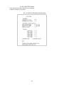
1
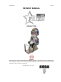
RND-0043 REV 0 SERVICE MANUAL UPRIGHT TYPE Before using this product, read this SERVICE MANUAL carefully to understand the contents stated herein. After reading this manual, be sure to keep it available nearby the product or somewhere convenient in order to be able to refer to it whenever necessary. Manufactured in the UK by CONTENTS 1. BEFORE USING THIS PRODUCT........................................................................................................1 1.1. INSPECTIONS IMMEDIATELY AFTER TRANSPORTING THE PRODUCT TO THE LOCATION ..2 2. INTRODUCTION TO THIS SERVICE MANUAL ...................................................................................4 3. INSTALLATION AND MAINTENANCE INSTRUCTIONS .....................................................................5 3.1. HANDLING AND INSTALLATION PRECAUTIONS ..........................................................................5 3.2. COIN HANDLING...............................................................................................................................5 3.3. NAME OF PARTS ..............................................................................................................................6 3.4. ACCESSORIES .................................................................................................................................7 3.5. ASSEMBLY INSTRUCTIONS ............................................................................................................9 3.5.1. INSTALLING THE PAYOUT ASSEMBLY. (SWP-1500UK ).....................................................10 3.5.2. INSTALLING THE BILLBOARD................................................................................................13 3.5.3. INSTALLING THE POP PANEL(SWP-7005UK) If Required....................................................14 3.5.4. SECURING IN PLACE (LEG ADJUSTER ADJUSTMENT)......................................................15 3.5.5. INSTALLING THE FLOOR .......................................................................................................16 3.5.6. SECURING IN PLACE (LEG ADJUSTER ADJUSTMENT)......................................................18 3.5.7. CONNECTION TO THE POWER SUPPLY..............................................................................20 3.5.8. FITTING THE LOCK BAR.........................................................................................................21 3.5.9. ASSEMBLY CHECK .................................................................................................................22 3.6. MOVING THE MACHINE .................................................................................................................24 3.7. CONTROL PANEL (HANDLE MECHA.) – ‘HAPP’ TYPE ................................................................26 3.7.1. REPLACING VOLUME .............................................................................................................26 3.7.2. GREASING – SEGA and HAPP types ......................................................................................28 3.7.3. REPLACEMENT OF SPRING ..................................................................................................29 3.8. ACCELERATOR AND BRAKE.........................................................................................................29 3.8.1. REMOVING THE ACCELERATOR AND BRAKE ....................................................................30 3.8.2. ADJUSTING OR REPLACING THE VOLUME .........................................................................31 3.8.3. GREASING ...............................................................................................................................32 3.9. REPLACEMENT OF FLUORESCENT LAMPS ...............................................................................33 3.9.1. FRONT FLUORESCENT:.........................................................................................................33 3.10. GAME BOARD .............................................................................................................................35 3.10.1. TAKING OUT THE GAME BOARD.......................................................................................35 3.10.2. COMPOSITION OF GAMEBOARD ......................................................................................37 3.11. TROUBLESHOOTING .................................................................................................................38 3.11.1. Hopper Assembly Fault Finding ............................................................................................39 3.12. COIN MECHANISMS ...................................................................................................................41 3.13. FUSES..........................................................................................................................................42 4. CONTENTS OF GAME .......................................................................................................................43 5. HOW TO PLAY....................................................................................................................................44 5.1. HOW TO PLAY: POUND setting......................................................................................................44 6. EXPLANATION OF TEST AND DATA DISPLAY ................................................................................47 6.1. INTERNAL SWITCHES AND COIN METERS.................................................................................48 6.2. SYSTEM TEST MODE.....................................................................................................................50 6.2.1. RAM TEST ................................................................................................................................51 6.2.2. JVS TEST .................................................................................................................................52 6.2.3. INPUT TEST SCREEN .............................................................................................................52 6.2.4. SOUND TEST ...........................................................................................................................53 6.2.5. CRT TEST ................................................................................................................................53 6.2.6. SYSTEM ASSIGNMENTS ........................................................................................................54 6.2.7. COIN ASSIGNMENTS ..............................................................................................................55 6.2.8. BOOKKEEPING........................................................................................................................56 6.2.9. BACKUP DATA CLEAR............................................................................................................56 6.2.10. CLOCK SETTING .................................................................................................................57 6.2.11. DIMM BOARD TEST .............................................................................................................57 6.3. GAME TEST MODE.........................................................................................................................58 6.3.1. GAME TEST MENU screen......................................................................................................58 6.3.2. INPUT TEST screen .................................................................................................................58 6.3.3. OUTPUT TEST screen .............................................................................................................59 6.3.4. GAME SETTING Screen ..........................................................................................................60 6.3.5. HOPPER TEST MENU Screen.................................................................................................61 6.3.5.1. INPUT TEST screen..........................................................................................................62 6.3.5.2. OUTPUT TEST screen......................................................................................................63 6.3.5.3. COIN TEST screen............................................................................................................64 i TROUBLE LOG screen .....................................................................................................65 6.3.5.4. 6.3.6. PAYOUT SETTING (CREDIT SETTING) screen .....................................................................67 6.3.6.1. BRITISH STERLING POUND setting ................................................................................67 6.3.7. VOLUME SETTING screen ......................................................................................................68 6.3.8. POUND BOOKKEEPING setting ..............................................................................................69 6.3.8.1. BOOKKEEPING 1/4 screen...............................................................................................69 6.3.8.2. BOOKKEEPING 2/4 Screen ..............................................................................................69 6.3.8.3. BOOKKEEPING 3/4 Screen ..............................................................................................70 6.3.8.4. BOOKKEEPING 4/4 Screen ..............................................................................................71 6.3.9. 2.TOKEN BOOKKEEPING .......................................................................................................73 6.3.9.1. BOOKKEEPING 3/9 Screen ..............................................................................................73 6.3.9.2. BOOKKEEPING 5/9 Screen ..............................................................................................73 6.3.9.3. BOOKKEEPING 6/9 Screen ..............................................................................................74 6.3.9.4. BOOKKEEPING 7/9 Screen ..............................................................................................75 6.3.9.5. BOOKKEEPING 8/9 Screen ..............................................................................................76 6.3.9.6. BOOKKEEPING 9/9...........................................................................................................77 6.3.10. BACKUP DATA CLEAR Screen............................................................................................78 7. PERIODIC CHECK AND INSPECTION ..............................................................................................79 7.1. CLEANING THE CABINET SURFACES..........................................................................................79 8. DESIGN RELATED PARTS.................................................................................................................80 9. APPENDIX A - ELECTRICAL SCHEMATIC........................................................................................81 9.1. WIRE COLOURS .............................................................................................................................81 9.2. ELECTRICAL SCHEMATIC .............................................................................................................81 ii 1. BEFORE USING THIS PRODUCT To ensure the safe usage, be sure to read the following before using the product. The following instructions are intended for the use of QUALIFIED SERVICE PERSONNEL ONLY. If any activity is carried out on the product, this should be done only after carefully reading and sufficiently understanding the instructions. Only qualified service personnel should carry out maintenance on the product. Depending on the potential risk, terms such as” WARNING!” “CAUTION” and “IMPORTANT!” are used where an explanation is given that requires special attention. SEGA is not responsible for injury or damage caused by use in a manner contrary to the instructions given in this document. In order to prevent accidents warning stickers and printed instructions are applied in the places where a potentially hazardous situation relating to the product could arise. Be sure to comply with these warnings. Indicates that mishandling the product by disregarding this warning will cause a potentially hazardous situation that can result in death or serious injury. Indicates that mishandling the product by disregarding this caution will cause a potentially hazardous situation that can result in personal injury and or material damage. This is cautionary information that should be complied with when handling the product. Indicates that mishandling the product by disregarding this will cause a potentially hazardous situation that may not result in personal injury but could damage the product. Be sure to turn off the power and disconnect from the mains supply before working on the machine. Ensure that the correct fuses are fitted to the machine. Details of these are enclosed in the Service Manual. Ensure that only qualified Service Engineers perform any maintenance work on the machine. Specification changes, removal of equipment, conversion and/or additions not designated by SEGA are not permitted and will invalidate this product’s CE conformity. Warning labels or safety covers for personal protection etc, are component parts of the product. A potential hazard will be created if the machine is operated while any parts have been removed. Do not operate the product if any doors, lids or protective covers become damaged or lost. SEGA is not liable in any whatsoever for any injury and/or damage caused by specification changes not designated by SEGA. Before installing the product, check for the Electrical Specification Sticker, SEGA products have a sticker on which the electrical specifications are detailed. Ensure that the product is compatible with the power supply voltage and frequency requirements of the location in which the machine is to be installed. Install and operate the machine only in places where appropriate lighting is available, allowing warning stickers to be clearly read. To ensure maximum safety for customers and operators, stickers and printed instructions describing potentially hazardous situations are applied to potentially hazardous locations. Ensure that the product’s operating location has sufficient lighting to allow any warnings to be read. If any sticker or printed warning is removed or defaced, do not operate the machine until an identical item has replaced it. Exercise great care when handling the monitor (applies only to product with monitor). Some of the monitor (TV) parts are subject to high-tension voltage. Even after turning the power off some components are liable to hightension voltage. Only qualified service engineers should perform monitor repair and replacement. In cases where commercially available monitors and printers are used, only the items relating to this product are contained in this manual. Some commercially available equipment will have functions and reactions not referred to in this manual. This manual should be read in conjunction with the specific manufacturer’s manual for such equipment. Descriptions contained herein may be subject to change without prior notification. The contents described herein are fully prepared with due care. However, should any question arise or errors be found please contact SEGA AMUSEMENTS EUROPE LTD. Descriptions contained herein may be subject to change without prior notification. The contents described herein are fully prepared with due care. However, should any question arise or errors be found please contact SEGA. 1 1.1. INSPECTIONS IMMEDIATELY AFTER TRANSPORTING THE PRODUCT TO THE LOCATION · Only QUALIFIED SERVICE PERSONNEL should carry out inspection. Normally, at the time of shipment, SEGA products are in a state to allowing usage immediately after transporting to the location. Nevertheless, an irregular situation may arise during transportation preventing this. Before turning on the power, check the following points to ensure that the product has been transported safely. · Are then any dented parts or defects (cuts, etc.) on the external surfaces of the product? · Are castors and leg adjusters present and undamaged? · Do the power supply voltage and frequency requirements meet with the local supply? · Are all wiring connectors correctly and securely connected? Unless connected in the correct direction, connector connections cannot be made successfully. Do not insert connectors forcibly. · Are all IC’s of each IC BD firmly inserted? · Does the power cord have any cuts or dents? · Do fuses meet the specified rating? · Are such units such as monitors, control equipment, IC BD, etc. firmly secured? · Are all earth wires connected? · Are all accessories available? · Can all doors and lids be opened with the accessory keys and/or tools? 2 CONCERNING THE STICKER DISPLAY CONCERNING WARNING STICKERS SEGA product has stickers describing the product manufacture number (Serial Number) and electrical specification. If you require service assistance you will require the Serial Number. Identical machines may have different parts fitted internally. Only by quoting the Serial Number will the correct parts be identified. SEGA product has warning displays on stickers, labels or printed instructions adhered/attached to or incorporated in the places where hazardous situations can arise. The warning displays are intended for the accident prevention of customers and service personnel. Actual machine may differ from that illustrated above SPECIFICATIONS (With payout box attached) Installation Space (cm): 92 (W) x 150 (D) Assembled: 103 (W) (with Pop Panel) Height (cm): 180 210 (with Billboard) 243 (with Pop Panel) Weight (with floor and seat) (kg): Approx. 225 Power, Max: 414W Rated Voltage (VAC): 230 Rated Current (mA): 1.5 Operating Temperature Range 5 - 40°C Note: Descriptions in this manual are subject to change without prior notice. 3 2. INTRODUCTION TO THIS SERVICE MANUAL SEGA ENTERPRISES LTD., supported by its experience in electronic high technology of VLSI’s, microprocessors etc. and with a wealth of experience, have for more than 30 years been supplying various innovative and popular games to the world market. This Service Manual is intended to provide detailed descriptions together with all the necessary information covering the general operation of electronic assemblies, electro-mechanicals, servicing controls, spare parts, etc. as regards this new SEGA product. This manual is intended for those who have knowledge of electricity and technical expertise especially in IC’s, CRT’s, microprocessors etc. Carefully read this manual to acquire sufficient knowledge before working on the machine. Should there be any malfunction, non-technical personnel should under no circumstances touch the internal systems. Should such a situation arise contact the nearest branch listed below, or our head office. SEGA AMUSEMENTS EUROPE LTD./ SEGA SERVICE CENTRE Suite 3a Oaks House 12 - 22 West Street Epsom Surrey United Kingdom KT18 7RG Telephone: +44 (0) 1372 731820 Fax: +44 (0) 1372 731849 4 3. INSTALLATION AND MAINTENANCE INSTRUCTIONS · Only QUALIFIED SERVICE PERSONNEL should carry out installation and maintenance. 3.1. HANDLING AND INSTALLATION PRECAUTIONS When installing or inspecting the machine, be very careful of the following points and pay attention to ensure that the player can enjoy the game safely. The game must NOT be installed under the following conditions: · Outside, the game is designed for indoor use only. · In areas directly exposed to sunlight, high humidity, dust, excessive heat or extreme cold. · In locations that would present an obstacle in the case of an emergency i.e. near fire equipment or emergency exits. · On unstable surfaces or surfaces subject to vibration. · Where liquids, other than routine cleaning, may come into contact with the game. Important: · Only Qualified Service Personnel should install this machine. · Be sure to switch the supply power OFF and remove the mains supply plug from the machine before any work is carried out on the machine. · Do not attempt to repair the PCB’s (Printed Circuit Boards) yourself. This will void the warranty. The PCB’s contain static sensitive devices that could be damaged. · Always return a faulty part to your distributor with adequate packaging and protection. · When removing the plug from the mains always grasp the plug not the cable. · Do not use a fuse that does not meet the specified rating. · Make sure all connections are secure before applying power. 3.2. · Ensure that the mains lead is not damaged. If the mains lead is damaged in any way there could be a danger of electric shock or a fire hazard. · Ensure that the power supply is fitted with circuit protection. Using the power supply without circuit protection is a fire hazard. COIN HANDLING Standard Sega machines are fitted with a SR3 coin mechanism. Approved coin handling options: · Coin controls SR3 Money Controls front entry only. 5 3.3. NAME OF PARTS Width (cm) Length (cm) Height (cm) CABINET 92 105 180 FLOOR 63 71 15 BILLBOARD (with Pop Panel) 103 - 63 WHEN ASSEMBLED 103 147 243 6 3.4. ACCESSORIES The machine is supplied with an installation kit. Please ensure the following parts are supplied: ITEM 1 2 3 4 8 9 14 16 17 18 22 101 201 202 203 204 205 206 402 406 407 408 409 411 412 413 414 PART NO. QTY. Description NOA-1301X 1 BILLBOARD PLATE CKT-7500UK 1 ASSY FLOOR CTA-0001 1 JOINT BRKT L CTA-0002 1 JOINT BRKT R CKT-7001UK 1 DISPLAY CARD CKT SWP NOA-1302UK 1 BILLBOARD SHEET CKT-7002UK 1 PLAY INSTR SH MULTI SWP CKT-7004UK 1 SUB INSTR SH MULTI SWP SWP-7005UK 1 POP PANEL SWP 420-5827 1 SERVICE MANUAL SANWA 31K NOB-0004UK 1 LOCK BAR C 514-5078-5000 1 FUSE 5X20 CERAMIC SB 5000mA 030-000820-SB 2 M8X20 BLT W/S BLK 068-852216-0B 2 M8 WSHR 22OD FLT BLK 008-T00412-0C 2 M4X12 TMP PRF TH CRM 008-T00425-0C 3 M4X25 TMP PRF TH CRM 050-F00400 3 M4 NUT FLG SER PAS 068-441616-0C 3 M4 WSHR 16OD FLT CRM RND-0043 1 SERVICE MANUAL CKT SWP OS1019 1 SELF SEAL BAG 9X12.3/4 PK0328 1 INST KIT BOX CKT SWP PK0061 0.025 BUBBLE WRAP LARGE 1.5M X 45M 220-5484-H 1 VOL 5-K-OHM HAPP 50-8026-00 540-0006-01 1 WRENCH M4 TMP PRF 540-0007-01 1 WRENCH M5 TMP PRF 540-0009-01 1 WRENCH M8 TMP PRF 540-0015-01 1 WRENCH M6 TMP PRF Component Reference fix via padlock over cash box door (3)-1,(4)-1 (3)-1,(4)-1 (1)-2 (9)-3 (17)-3 (17)-3 SPARE Items 411 to 414 - Tamperproof TORX wrench. 7 · When returning the GAME BOARD for repair or replacement, be sure to package the entire ASSY SHIELD CASE in the original card transit box - THERE ARE NO USER-SERVICEABLE PARTS INSIDE. · Failure to return the GAME BOARD in this manner may invalidate the warranty. Wrap the ASSY SHIELD CASE with the packaging material and put it in the original transit box as shown. Putting it upside down or packing otherwise in the manner not shown can damage the GAME BOARD and parts. 8 3.5. ASSEMBLY INSTRUCTIONS · Perform the assembly by following the procedure herein stated. Failure to comply with the instructions, for example, inserting the plug into an outlet at a stage not mentioned in this manual can cause an electric shock · Assembling should be performed as per this manual. Since this is a complex machine, erroneous assembling can cause damage to the machine, or malfunction to occur. · Do not attempt to complete this work alone, a minimum of 2 people are required. · Only QUALIFIED SERVICE PERSONNEL should carry out assembly. When carrying out the assembly work, follow the procedure in the following sequence: STEP 1 INSTALLING THE PAYOUT ASSEMBLY. (SWP-1500UK ) STEP 2 INSTALLING THE BILLBOARD STEP 3 INSTALLING THE POP PANEL(SWP-7005UK) If Required STEP 4 SECURING IN PLACE (LEG ADJUSTER ADJUSTMENT) STEP 5 INSTALLING THE FLOOR STEP 6 CONNECTION TO THE POWER SUPPLY STEP 7 FITTING THE LOCK BAR STEP 8 ASSEMBLY CHECK Note that the parts contained within the installation kit are required for the assembly work. The following tools will be required when installing this machine, in addition to the tools provided with the Installation Kit: 9 3.5.1. INSTALLING THE PAYOUT ASSEMBLY. (SWP-1500UK ) Tools required: M4 tamperproof torx wrench Socket Wench, Ratchet Handle + sockets for M6 & M4 bolts Phillips type screwdriver *Take Payout Box (SWP-1500UK) carefully out of packaging and place on convenient work surface *To gain access to the various fixings it is necessary to remove some of the internals of the box namely the hopper shelf assy (SWP-1530UK) and the payout tray (SWP1502UK). This is done as follows: - 1. 10 Open the front door of the payout box by loosening the M4 security screw (008T00430-0C) to the right of the lock hence allowing the lock cam to be turned With Key. 2. 3. Remove the hopper shelf by disconnecting the electrical plug to the right, unlocking via the key at the front and sliding out toward you via the red handle taking care not to trap any cables. Remove the payout tray by removing the 2x M6 screws (000-P00616-W) at the rear, disconnecting any earthing in this area, shutting the front door and removing the 4x M4 security screws (008T00412-0C) in the front. The payout Tray can now be removed forwards (Please take with paintwork on box front face). Be careful so as not to trap any cables. 11 NB. Machine may differ from above illustration. · Offer the Payout Box up to the main machine ensuring that the protruding ‘chute’ in the left hand side of the box mates up with the corresponding one in the coin chute (SWP-1007UK) at the rear. An additional person may be of help in this operation. Feed the cables from the upright machine through first to ensure they do not get damaged. In case of a tight fit it may be necessary to remove the upper extrusion (and hence top ‘hoof’). Secure by loosely putting in the top 2x M6 bolts (030-000612-S) and bottom 2x M6 bolts on the base of the payout box. Put in the M6 bolt and large washer (068-652516) at the rear of the box attached to the rear fixing on the coin chute (SWP-1007UK) · Insert the remaining 4x M6 bolts located along the front inside left edge of the box and tighten all fixings up. Finish off by adding 2 off M6 dome nuts (050-C00600-3C) to back of bolts on underside and a further one to the back. · · Ensure that before the payout tray is re-inserted all plug connectors, including the Earthing Plug, on the machine and the payout box are connected (near to the cable routing aperture). Re-attach the payout tray and hopper shelf by following the reverse of the removal instructions above. Please care not to damage the box paintwork when reinstalling. · Ensure that the payout box at the end of the procedure is fully earthed to the main machine using the earthing looms provided within the assembly, this includes earthing of the payout tray and door assemblies. 12 3.5.2. INSTALLING THE BILLBOARD · Only QUALIFIED SERVICE PERSONNEL should carry out this operation. 1. Insert ASSY BILLBOARD to the top part of the cabinet 2. Secure with the two Tamperproof screws NB Take CARE NOT TO DAMAGE THE MACHINE ON THE 3 PROTRUDING THREADS ON THE BACK OF THE BILLBOARD ASSY. (008-T0425-OC) Note: Machine may differ slightly from above illustration. 13 3.5.3. INSTALLING THE POP PANEL(SWP-7005UK) If Required · Only QUALIFIED SERVICE PERSONNEL should carry out this operation. 1 Position Pop panel behind the billboard assembly using exsisting double –sided tape on pop panel. Ensure alignment of 3 holes with billboard. 2 Secure in place with 3 x M4Tamperproof screws Pt.No.008-T00425-oc along with 3xM4 washers Pt. No.068-441616-oc and 3 x M4 nuts Pt. No.050-F00400 Note: Machine may differ slightly from above illustration. 14 3.5.4. SECURING IN PLACE (LEG ADJUSTER ADJUSTMENT) · Make sure all of the leg adjusters are in contact with the floor. To prevent the machine from moving and causing injury. This operation requires 2 people. · Only QUALIFIED SERVICE PERSONNEL should carry out this operation. This machine has four castors and two leg adjusters. When the installation position is decided, unscrew the leg adjusters so that they raise both front castors 7mm from the floor. Make sure the machine is level. 1. Move the product into the installed position. 2. Unscrew the adjusters until they are in contact the floor, and use a wrench to turn them further until the front castors are raised approximately 7mm above the floor. 3. Tighten the locknut on the leg adjusters upwards to lock the legs in position. Ensure adequate ventilation is maintained as detailed below: 15 3.5.5. INSTALLING THE FLOOR · Ensure all connections are secure - poor connections can cause electric shock or short circuit. · Take care not to damage wiring during installation, as this can cause electric shock or short circuit. 16 7. Slightly lower the 2 Adjusters on the cabinet and install JOINT BRACKET L & R by inserting from the rear, and secure to ASSY FLOOR using hexagon bolts as shown. 8. After lowering the Adjusters fully downward, tighten both Adjuster’s lock nuts fully upward. 17 3.5.6. SECURING IN PLACE (LEG ADJUSTER ADJUSTMENT) · Make sure all of the leg adjusters are in contact with the floor. If not the machine may move and cause injury. This operation requires 2 people. · Only QUALIFIED SERVICE PERSONNEL should carry out this operation. This machine has four castors and two leg adjusters on the main cabinet, and a further two level adjusters on the rear of the floor. When the installation position is decided, unscrew the leg adjusters so that they raise both front castors 7mm from the floor. Make sure the machine is level. 1. Move the product into the installed position. 2. Unscrew the adjusters until they are in contact the floor, and use a wrench to turn them further until the front castors are raised approximately 7mm above the floor. 3. Tighten the locknut on the leg adjusters upwards to lock the legs in position. 18 If this product is installed on irregular surfaces, use the two Level Adjusters on the bottom of the FLOOR to ensure the product is level. Note: Machine may differ slightly from above illustration. 19 3.5.7. CONNECTION TO THE POWER SUPPLY · Be sure that the machine is not connected to the mains supply before attempting this operation · Only QUALIFIED SERVICE PERSONNEL should carry out this operation. 1. The AC Unit is located on the right hand side of the base unit, when viewing the screen. It houses the IEC inlet, mains switch and fuse. 2. Ensure that all of the machine’s wires have been connected in accordance with the preceding sections and that the mains switch is OFF. 3. Check that the operating voltage of the mains supply matches the machine (section 1.1). 4. Insert the IEC lead into the IEC inlet and the mains plug into a wall socket. If applicable, switch the wall socket ON. 5. Stand clear of the machine and switch the mains switch ON. 20 3.5.8. FITTING THE LOCK BAR Procedure This comprises a security bar to facilitate higher security for the Naomi Cabinet cash door (standard clamp-in SFMD type only). This does not include a padlock. Position LOCK BAR C with the long side flange to the left & hook the bottom slot underneath LOCK BAR A. Rotate LOCK BAR C up to the vertical and slide onto LOCK BAR B. It is now possible to fit your padlock. 21 3.5.9. ASSEMBLY CHECK In TEST MODE, ascertain that the product has been correctly assembled and the IC BD is functioning correctly (refer to ) by performing the following tests: Selecting the desired SELF TEST item on the test mode menu screen causes the on-board memory to be tested automatically. The game board is satisfactory if the display beside each IC number shows GOOD. In the TEST mode menu, selecting CRT TEST allows the screen (on which the monitor is tested) to be displayed. Although the monitor adjustments have been made prior to shipment from the factory, colour deviation ,etc. may occur due to the effects of geomagnetism, the building’s steel frame and other game machines in the periphery. By watching the test mode screen, make judgement as to whether adjustment is required. If so, adjust the monitor by referring to the Monitor manual supplied with this product. Use the DEMAG SW to remove colour deviation due to magnetisation. 22 (3) INPUT TEST: Select INPUT TEST on the test mode menu screen to test the input switches. Actuate each switch (for the COIN CHUTE test insert a coin into the coin inlet with the coin chute door open). If the display beside each parameter display ON when the input is made, the switch and wiring connections are satisfactory. (4) OUTPUT TEST: Select OUTPUT TEST from the menu in the test mode menu screen to test the output. If the lamp illuminates, the wiring connections are satisfactory. (5) SOUND TEST: Select SOUND TEST from the test mode menu screen to check function of sound BD and wiring connections. Check that the sound emitted from all speakers is satisfactory and of a desirable volume level. Perform the above tests during each monthly inspection. 23 3.6. MOVING THE MACHINE · When moving the machine, be sure to remove the plug from the power supply. Moving the machine with the plug inserted can cause the power cord to be damaged, resulting in a fire or electric shock. · When moving the machine, retract the leg adjusters fully and ensure the casters make contact with the floor. During movement pay careful attention so that the casters or leg adjusters do not damage any other cabling laid on the floor. Such damage could result in a fire or electric shock. · Do not push the upper part of the cabinet. Failure to observe this can cause the cabinet to fall forwards and result in accidents. · When transporting the machine, be sure to hold the catch portion on the rear of the cabinet with the castors making contact with the surface as shown below. Inclining the machine by holding portions other than the catch or moving the cabinet without retracting the adjusters can damage the cabinet and/or the floor surface. · Do not push the Billboard. Failure to observe this may damage the installation portions and may cause unexpected accidents. · Only QUALIFIED SERVICE PERSONNEL should carry out this operation. Note: Machine may differ slightly from above illustration. 24 Note: Machine may differ slightly from above illustration. 25 3.7. CONTROL PANEL (HANDLE MECHA.) – ‘HAPP’ TYPE · Before starting work, ensure that the cabinet is isolated from the mains by switching off and removing the IEC mains lead from the wall outlet. · Be careful not to damage wiring. Damaged wiring can cause electric shock and short circuits. · When closing the Control Panel be very careful to avoid trapping fingers or hands. · Only QUALIFIED SERVICE PERSONNEL should carry out this procedure. 3.7.1. REPLACING VOLUME If the steering operability becomes poor, and adjusting the VOLUME SETTING in the TEST MODE in ineffective, the cause may be the failure of the Volume Gear to mesh and/or the Volume Potentiometer malfunctioning. When the Steering Wheel is rotated fully left or right, if the Volume shaft is rotating within the movable range, the Volume is not feared to be damaged. Use the procedure described herein to position the steering VR such that the correct centre value (refer to Section 5.3.5) is displayed when the Steering Wheel is at rest. 1. Power OFF the machine and remove the IEC lead from the wall outlet. 2. Remove the three tamperproof screws and open the Control Panel. 26 3. Loosen the two screws and adjust the gear mesh by moving the VR Bracket. 4. Adjust to an appropriate setting by securing the steering wheel in the straight ahead position. 5. After adjustment, check the volume setting as described in Section 5.3.5. If necessary, repeat steps 3 & 4 until the volume value is within allowable limits (±3H) HOW TO REPLACE 1. Disconnect the Volume Connector. 2. Take out the two screws and remove the Volume together with the VR Bracket. 3. After replacing the Volume, engage the gears at the angle shown and fix the VR Bracket. Close the Control Panel and replace the three tamperproof screws before turning power ON and setting the Volume value in the TEST MODE. 27 3.7.2. GREASING – SEGA and HAPP types · Use only synthetic grease (grease or spray) as plastic parts are used. Do not use mineral based greases. · Applying grease to parts other than those specified can cause malfunctioning or quality deterioration of parts. Apply grease to the gear mesh and cam portions once every three months. Use a proprietary synthetic lubricant.. SEGA type HAPP type 28 3.7.3. REPLACEMENT OF SPRING In case of spring damage or wear, open the Control Panel and replace the spring. SEGA type 3.8. HAPP type ACCELERATOR AND BRAKE · Before performing work, be sure to turn power off. Working with power on can cause an electric shock or short circuit. · Use care to ensure the wiring is not damaged. Damaged wiring can cause electric shock or short circuit. · Touching parts of the machine other than those specified here can cause electric shock of short circuit. · This procedure to be carried out only by QUALIFIED SERVICE PERSONNEL. If the operation of the Accelerator and Brake pedals is unsatisfactory and not remedied by adjustment of the VOLUME SETTING in the TEST MODE, the cause may be mesh failure of the Volume Gear or a faulty Volume potentiometer. Follow the procedure below to adjust the Volume Gear mesh or replace the Volume potentiometer. When the pedals are depressed fully, if the Volume shaft is rotating within the movable range, the Volume is not feared to be damaged. Use the procedure described herein to position the VR such that the correct values (refer to Section 5.3.5.) are displayed at both extremes of pedal travel. 29 3.8.1. REMOVING THE ACCELERATOR AND BRAKE 1. Turn the power switch OFF and remove the IEC cable. 2. Take out the four truss screws and remove the Floor Lid. 3. Take out the six hexagon nuts to remove the Accelerator (or Brake) Unit. 4. Disconnect the Connector and remove the Accelerator (or Brake) Unit. 30 3.8.2. ADJUSTING OR REPLACING THE VOLUME ADJUSTMENT: 1. Loosen the 2 screws, move the VR Bracket, and adjust the angle for optimum gear mesh. 2. Check the setting in Section 5.3. REPLACEMENT: 1. Take out the two screws and remove the Volume together with the VR Bracket. 2. After replacing the Volume, engage the gears at the angle shown, and fix the VR Bracket. 3. Install the Accelerator (or Brake) Unit and connect the connector. 4. Re-install in reverse order and replace the Floor Lid and IEC Cable before turning power ON. 5. Check the setting in Section 5.3. 31 3.8.3. GREASING · When performing work, be sure to turn power off. Working with power on can cause an electric shock or short circuit. · Use only synthetic grease (grease or spray) as plastic parts are used. Do not use mineral based greases. · Applying grease to parts other than those specified can cause malfunctioning or quality deterioration of parts. Apply grease to the gear mesh portions once every three months. Use a proprietary synthetic lubricant.. 32 3.9. REPLACEMENT OF FLUORESCENT LAMPS · Never touch places other than those specified. Touching places other than those specified can cause electric shock and short circuit. Disconnect the machine from the supply before attempting the replacement of any lamp. · When performing work, be sure to turn power off. Working with power on can cause an electric shock or short circuit. · Hot fluorescent lamps can cause burns. Be very careful when replacing them. · Use a secure step to improve access to the upper parts of the cabinet. · Only QUALIFIED SERVICE PERSONNEL should replace lamps. 3.9.1. FRONT FLUORESCENT: 1. Turn power OFF at the Main Switch and remove the IEC lead. 2. Open the Control Panel (see Section 3.7). 3. Remove the two truss screws and open the entry panel. 4. By using a flat bladed screwdriver, remove the four screw caps from the front panel. 5. Take out the four tamperproof screws and the two lower screws, and carefully take off the Front Panel. 6. Remove the Billboard assembly as detailed in Section 3.10.2. 7. Remove the four screws and the Earth Link to allow the Billboard Holder to be removed. 8. The Fluorescent lamp can be removed by disconnecting the two end caps and withdrawing the Lamp upwards through the two mounting clips. 9. After replacing the lamp, reassemble in reverse order, being sure to replace the Earth Link between the Billboard Holder and frame. 33 34 3.10. GAME BOARD · When performing work, be sure to turn power off. Working with power on can cause an electric shock or short circuit. · Be careful not to damage wiring. Damaged wiring can cause an electric shock or short circuit. · The voltage/amperage ratings for the Game Board are 3.3V 12A, 5.0V 10A and 12V 2A. To avoid risk of fire, never use any board with supply requirements exceeding the above. · When replacing the Game Board with one not of JAMMA standard, be sure to use only the harness supplied by the manufacturer of the Game Board. Using other harnesses constitutes a fire risk. · Only QUALIFIED SERVICE PERSONNEL should carry out this operation. 3.10.1.TAKING OUT THE GAME BOARD To take out the Game Board (NAOMI SHIELD CASE), remove together with the wooden base on which the Game Board is mounted. If the Game Board is faulty, return to SEGA within the original packaging provided. There are no user-serviceable parts inside. 1. Turn power OFF and remove the IEC lead from the wall socket. 2. Disconnect the Filter Board. Also disconnect all the devices, other than the Naomi, on the base. Disconnect the pedals. 35 3. Remove the screws securing the wooden Base and remove it from the cabinet together with the Shield Case, as detailed below. Be careful not to damage wiring during removal. 4. Take out the four screws and remove the Shield Case. 36 3.10.2.COMPOSITION OF GAMEBOARD · Only QUALIFIED SERVICE PERSONNEL should carry out these procedures. · Ensure the DIP SW setting if performed as designated. Failure to observe this may cause malfunctioning. 37 3.11. TROUBLESHOOTING · Only QUALIFIED SERVICE PERSONNEL should carry out these procedures. If a problem occurs, first check the wiring connections. PROBLEMS When the main switch is turned ON, the machine is not activated The colour image on the screen is incorrect CAUSE COUNTERMEASURES The power is not ON. Firmly insert the plug into the outlet. Incorrect power source/voltage. Make sure that the power supply/voltage are correct. AC Unit CIRCUIT PROTECTION DEVICE (ie; fuse) was activated due to an instantaneous overcurrent. First, remove the cause of overcurrent and reinstate the circuit protection device to its original status. Then identify the cause of the fault on the item which caused the overcurrent & fix. Incorrect monitor adjustment. Make appropriate adjustments. Refer to the Monitor Service Manual supplied with this product. The on-screen image of the The power source and voltage are not monitor sways and/or shrinks correct. Sound is not emitted The fluorescent lamp does not light up Steering Wheel does not operate satisfactorily. Operation of Accel & Brake Pedals is not satisfactory. Make sure that the power supply and voltage are correct. Sound volume adjustment is not correct. Adjust the volume setting on the VTS bracket. Refer to the Monitor Service Manual supplied with this product. Malfunctioning BD and Amp. Perform Sound Test to check it. Refer to the Monitor Service Manual supplied with this product. Connector connection is incorrect Check connector connection from Base to Speaker/Woofer Fluorescent lamp needs replacement Replace the fluorescent lamp. Refer to the Monitor Service Manual supplied with this product. The connector is disconnected Steering Wheel deviation. Check connector connections in the billboard case. Refer to the Monitor Service Manual supplied with this product. Adjust Volume value in the TEST MODE. Steering Wheel Volume malfunctioning. Replace the Volume (see Section 3.7). ADJUST GEAR’s engagement in not correct. Adjust the engagement of ADJUST GEAR (see Section 3.7). VR position deviated. Adjust the VR value in the TEST MODE. VR malfunctioning. Replace the VR (see Section 3.9). ADJUST GEAR’s engagement is not correct. Adjust the adjustment of ADJUST GEAR (see Section 3.9). 38 Continued. PROBLEMS No coin recognition. Or Poor coin acceptance rate Machine not paying out. CAUSE COUNTERMEASURES Coin mech dirty. Clean mech. Coin mech faulty. Replace coin mech. Bad loom connections. Check all harness connections for loose wires and fitments. Mech not programmed. Replace mech. Payout Gameboard faulty. Replace Payout Gameboard. No coins or coins jammed in Hopper. Add coins or clear jam. Faulty Hopper or Hopper drive PCB Replace hopper or drive PCB Faulty Hopper internal or external loom to Check connectors. motherboard or drive PCB 24V DC fuse blown on hopper drive board. Machine Error Check fuse. Payout Gameboard faulty. Replace Payout Gameboard. See Trouble Log Section 6.3.5 Follow trouble log guidance (use reset switch, located beneath Payout tray, if error persists). 3.11.1.Hopper Assembly Fault Finding Coins fail to unjam 1. Ensure coin exit clear. 2. Ensure no incorrect coins or foreign objects are in the hopper. 3. Ensure no badly bent coins in hopper Clearing a coin jam 1. Remove hopper shelf assembly from machine by disconnecting cable, unlocking shelf and withdrawing using handle 2. Remove bowl cover (via 2 screws) 3. Remove all coins from bowl 4. Remove motor assembly from base as described earlier. 5. Clear the jammed coin by either: OR a. b. NB. 6. 7. 8. 9. Rotating the disc manually first anti-clockwise then clockwise to free the coin. Push the coin back in using the edge of similar coin. Common cause is damaged or bent coins. Do not return damaged coins to bowl. Remove any debris from the disc bed assembly. Clean the exit window opto with a clean dry cloth. Reassemble as described earlier. Refill and test the hopper. Motor fails to run. 1. Check 24v 5A fuse on the Hopper Drive Board. 2. Hopper over-current protective device tripped (Wait 30 seconds while supply off). Over payout of coins 1. Check opto area/coin exit for dirt. Under Payout of coins 1. Ensure hopper contains sufficient coins. 2. Poor connection (check common return wires) to hopper. 39 MAINTENANCE - COIN CONTROLS 24V DC HOPPER ASSEMBLY Hopper Operation: Each disc contains a number of holes in which coins are held in short stacks. The motor drives the disc via a gear train. As the disc rotates, the coin at the bottom of one of the stacks will make contact with the ejector fingers and start to push the fingers back. Further rotation of the disc will cause the coin to start to move outwards into the exit slot. At this point the spring will be free to pull the ejector fingers forward and push the coin through the exit slot. A LED transmitter and opto-receiver form an optical detector. The infrared light beam is routed across the exit slot via a light guide. When coin passes through the exit the light beam will be broken and coin output signal will be generated. The hopper will automatically brake when power is interrupted, or machine placed in the off state, thus preventing overrun and excessive coin payout. An over current detection circuit reverses the hopper momentarily in the event of a coin jam, and then attempts to continue payout. This oscillation of the disc will continue until either the coins are freed, the hopper is switched off, or the overload trip switches. Should the latter occur the hopper supply must be disconnected, the fault condition must be corrected and the trip be allowed time to cool (Approx. 30 seconds) before the hopper will start. Dismantling the Hopper 1. Remove bowl cover (via 2 screws) 2. Gently pull outwards the securing clips on the back of the base. 3. Tilt the bowl forward until it is clear of the clips. 4. Slide the bowl forward until the locating lugs, at the front of the bowl, are clear of the slots in the base. 5. Lift the motor assembly out of the base. 6. Disconnect the cable from the motor assembly. Hopper Assembly 1. Connect the cable to the motor assembly, ensuring that the 4-pin connector is the correct way round. 2. Lower the motor assembly into the base, ensuring that the coin exit is in the rear exit position. (Towards Coin exit position as shown on hopper diagram). 3. Locate the lugs, on the front of the bowl, into the slots at the front of the base. 4. Gently press down until the securing clips, on the base, click into the slots in the bowl. 5. Replace bowl cover and secure (via 2 screws) Routine cleaning: All accessible parts of the coin route should be cleaned periodically using a mild detergent on a damp cloth. No spray solvents should be used. Particular attention should be paid to the opto sensor at the coin exit to remove any build up of dirt. 40 3.12. COIN MECHANISMS COINS ACCEPTED: 5P, 10P, 20P, 50P, £1 COIN ROUTING (Active routing of £1 controlled by Coin Count) £1 to Route B excess to Route A (cashbox), All other coins routed to Route A (cashbox) SR5 – COIN CONTROL ROUTING PLUG: 18 WAY Cash Payout - £1 Hopper only fitted 5-7, 8-15, 11-13 (Pt No 034138) 41 3.13. FUSES · Never touch places other than those specified. Touching places other than those specified can cause electric shock and short circuit. Disconnect the machine from the supply before attempting the replacement of any fuse. · Only QUALIFIED SERVICE PERSONNEL should replace FUSES. · Only replace fuses with ones of the same value and type. There are a number of fuses used on this machine to protect the user and the machine from damage. Only replace the fuse once you have removed the cause of its failure. Detailed below is a list of the fuses used, their location and if relevant PCB reference: PART NUMBER 514-5078-3150 514-5078-4000 514-5078-5000 514-5078-6300 LOCATION TYPE & DETAILS STEREO AMP REF. F1, F2 SWITCH REG REF. F1 IEC INLET REF. F1 CONN. BD. REF. F1 5x20mm 5x20mm 5x20mm 5x20mm CERAMIC SB 3.15A CERAMIC SB 4A CERAMIC SB 5A CERAMIC SB 6.3A QTY 2 1 1 1 There are also fuses located on the Monitor PCB. Refer to the relevant Monitor manual supplied to reference these fuses. 42 4. CONTENTS OF GAME The following information assumes that the product is functioning satisfactorily. Should there be any discrepancies, a fault may have occurred. In this case, examine the machine to ascertain and eliminate the cause of the fault to ensure satisfactory operation. The fluorescent lamp is always lit when the product is connected to the mains supply. During Advertise mode, the two speakers and the woofer output the Advertise sounds and the Advertise screenplay sequence appears on the monitor. HOW TO OPERATE: The Steering Wheel, Accelerator and Brake Pedal function as on a car. 43 5. HOW TO PLAY 5.1. HOW TO PLAY: POUND setting 1. Insert Coin 2. Press START BUTTON 3. Select the difficulty level between; novice, intermediate, difficult by using the steering, and then confirm by pressing ACCELERATOR UNIT or START BUTTON. 4. DOSH DASH RACE If you fail to reach goal within the time restriction it will be GAME OVER. There are many items within the circuit. Aim for star mark, avoid for skull mark, and then attempt to reach the goal within the time restriction. Time bonus will be added when reaching goal, try for further bonus time by reaching goal in certain time period. 44 5. ALL OR NOTHING STAGE Please press BRAKE UNIT in proper time, taking wind gauge in account, to stop KART within STOP AREA. The ACCELERATOR UNIT will NOT be used. If you succeed, you can win the prize achieved in “4.DOSH DASH RACE”. If you fail, it will be GAME OVER. 6. Continue If you fail in 5.ALL OR NOTHING STAGE, you can retry ONCE. If you wish to continue, please insert coin within time restriction. 45 7. DOUBLE UP CHALLENGE If you succeeded in both above 5 & 6, you have a chance of doubling up the prize. Look carefully for WIN and LOSE door, and aim for WIN gate. If you WIN prize doubles, but if you LOSE it will be GAME OVER and no prize paid out. This “7.DOUBLE UP CHALLENGE” feature can be either set ON or OFF. 46 6. EXPLANATION OF TEST AND DATA DISPLAY Use the switches on the VTS to enter the TEST MODE. This will allow you to carry out post installation and periodic checks and adjustments. The following section details the function of each of the tests: ITEM INSTALLATION OF THE MACHINE DESCRIPTION When the machine is installed perform the following checks: INTERVAL Monthly · Check to see that each setting is as per the standard settings input at the time of shipment. · In the INPUT TEST mode, check each switch and V.R. · In the OUTPUT TEST mode, check each of the lamps. · In the MEMORY TEST mode check all of the IC’s on the IC BD. MEMORY · On the TEST MENU screen choosing the MEMORY TEST allows self-test to be performed. In this test RAM & ROM are tested. Monthly PERIODIC CHECKS Periodically perform the following Monthly · MEMORY TEST. · Ascertain each setting. · In the INPUT TEST mode, test the control devices. · In the OUTPUT TEST mode, check each of the lamps. CONTROL SYSTEM · In the INPUT TEST mode, check each switch and V.R. Monthly · Adjust or replace each switch and V.R. MONITOR IC BOARD · In the C.R.T. TEST mode, check to ensure the monitor is adjusted correctly Monthly · Clean screen (switch off machine and remove the plug) Weekly MEMORY TEST Monthly · In the SOUND TEST mode, check the sound related ROMs DATA CHECK · Check such data as held in the bookkeeping screens, relating to number and length of plays Monthly EXTERIOR MAINTENANCE · Clean surfaces Monthly COIN MECHANISM · Check switch operation (if fitted) · Lubricate seat sliders 47 Monthly 6.1. INTERNAL SWITCHES AND COIN METERS · Never touch places other than those specified. Touching places not specified can cause electric shock and short circuits · Be careful not to damage wiring. Damaged wiring can cause electric shock and short circuits. · Adjust to the optimum sound volume considering the environmental requirements of the installation location. The Internal Switches can be found underneath the control panel via the door to the right of the woofer. NB: MAY BE ORIENTATED DIFFERENTLY (1) Test Switch Push to enter Test Mode of Game board, (4) DEMAG. Switch Removes on – screen colour deviation due to crt magnetisation, Use this Switch before monitor colour adjustment. (5) SOUND VOLUME Adjust the Speaker volume. (6) WOOFER VOLUME Adjust the woofer volume. 48 · If the COIN METERS and the Game Boards are electrically disconnected, game play is not possible under normal gaming procedures. Machine may differ from illustration Above. 49 6.2. SYSTEM TEST MODE · Setting changes made in SYSTEM ASSIGNMENTS, COIN ASSIGNMENTS and GAME TEST MODE are stored only when the TEST mode is exited properly. If the power is turned off before exiting, and changes made will be ineffectual. · Do not activate any system test mode while the system is reading the GD-ROM, otherwise error messages may appear. · Only QUALIFIED SERVICE PERSONNEL should carry out these procedures. The SYSTEM TEST MODE allows the IC Board to be checked for correct operation, monitor colour to be adjusted, and COIN and GAME ASSIGNMENTS to be adjusted. 1. After turning power ON, press the TEST Button to display the following menu: 2. Press the SERVICE Button to move the arrow to the desired item, and press TEST to select. 3. Select GAME TEST MODE to display the test menu for that specific game. For further information about GAME TEST MODE, refer to the service manual for the game. 4. Upon finishing the test, select EXIT to return to the game. 50 6.2.1. RAM TEST This screen carries out a test on the RAM on the NAOMI Main Board. The test begins immediately that the screen appears. TESTING NOW is displayed while the system is testing. GOOD should appear next to each IC number if the RAM is satisfactory. BAD will appear next to abnormal IC’s. The test takes about two and a half minutes to complete testing on all IC’s. After testing, press TEST to return to the system menu screen. 51 6.2.2. JVS TEST Use this test to check specifications of the I/O Board connected to the NAOMI Main Board, while INPUT TEST can be performed on the input switches. First, I/O Board specifications are displayed. Select from the following: INPUT TEST: Proceed to the INPUT TEST of the I/O BOARD displayed. NEXT NODE: In the case of more than two I/O Boards being connected, this proceeds to the next I/O Board. EXIT: Returns to the Menu Mode. 6.2.3. INPUT TEST SCREEN 52 6.2.4. SOUND TEST Select the sound test to check the status of the amplifiers, sound boards and speakers. Press the SERVICE button or view change button to move the arrow to the desired test item. Press TEST button to output the sound. · Select the sound source with SERVICE. · On pressing TEST, the test sound is emitted from the selected source. Front speakers are located on the Control Panel. Rear speakers are located in the seat back. Select EXIT to return to MENU screen. 6.2.5. CRT TEST Selecting CRT test allows the projector adjustment to be checked for colour and distortion. C.R.T. TEST 1/2 C.R.T TEST Press the test or start button to have the second CRT test screen appear. PAGE 1/2 RED GREEN BLUE WHITE PRESS TEST BUTTON TO CONTINUE C.R.T. TEST 2/2 PRESS TEST BUTTON TO EXIT 53 6.2.6. SYSTEM ASSIGNMENTS · If the settings of CABINET and MONITOR TYPE are not suitable for the connected game, an ERROR message is displayed when the game is turned on and TEST mode has finished, and the game cannot be played. Refer to the game’s service manual for the correct settings, or enter settings corresponding to the cabinet and control panel specifications. · Only QUALIFIED SERVICE PERSONNEL should carry out these procedures. This mode configures the cabinet and board settings. For settings relating to game difficulty, etc., refer to the dedicated service manual for the game software. 1. Select the setting to be changed using SERVICE and TEST. 2. Select EXIT after settings have been performed. · CABINET TYPE [1PLAYER(S), 2PLAYER(S), 3PLAYER(S), 4PLAYER(S)] Sets the number of players between one and four. · ADVERTISE SOUND (ON, OFF) Sets whether ADVERTISE sound is emitted or not. · MONITOR TYPE (HORIZONTAL, VERTICAL) · SERVICE TYPE (COMMON, INDIVIDUAL) Sets the on-screen display according to the orientation of the monitor. If several SERVICE buttons exist, this setting decides the function. COMMON: Service credit is obtained for all players when any SERVICE button is pressed. INDIVIDUAL: used. Service credit is obtained for the player corresponding to the SERVICE button 54 6.2.7. COIN ASSIGNMENTS Ensure machine is set to 1 Coin 1 Credit. Go to Game Test menu for further coin test settings. 55 6.2.8. BOOKKEEPING This mode consists of 2 pages that allow the data relating to credit and game play time to be checked. In page 1 mode press SERVICE to proceed to page 2, in page 2 mode press TEST to return to the test menu. · Total time is displayed as XXH XXM XXS and no date will be displayed after exceeding 24 hours. · The displays for number of coin and number of service vary depending on the CABINET TYPE set in SYSTEM ASSIGNMENTS. Number of credit displays 1 if COIN CHUTE TYPE is set to COMMON in COIN ASSIGNMENTS. If COIN CHUTE TYPE is set to INDIVIDUAL, the applicable number in CABINET TYPE setting will be displayed. · On the second screen, each sequence displays the frequency of functioning. 6.2.9. BACKUP DATA CLEAR Clears the contents of bookkeeping. When clearing bring the arrow to “YES (CLEAR)” and press the test button. When the data has been cleared “COMPLETED” will be displayed. Bring the arrow to “NO (CANCEL)” and press the test button to return to the menu mode. Note that this does not clear the contents of BOOKKEEPING in GAME TEST MODE. For this, use the BACKUP DATA CLEAR in GAME TEST MODE (see dedicated service manual for the game software). 56 6.2.10.CLOCK SETTING YEAR, MONTH, DAY, HOUR and MINUTE are changed in this mode. Select the desired item with SERVICE button and press TEST to increase the value. Select EXIT to return to MENU mode. 6.2.11.DIMM BOARD TEST This mode appears only if a DIMM Board is connected to the NAOMI. If not, ROM BOARD TEST will appear. In this test, the DIMM memory and IC’s are checked. If GOOD is displayed, it is satisfactory. Press TEST to exit. 57 6.3. GAME TEST MODE Cursor à will scroll downwards if you press SEVICE BUTTON. Please press TEST BUTTON when cursor is on required column. 6.3.1. GAME TEST MENU screen When selecting EXIT and press TEST BUTTON, you can return to SYSTEM TEST MENU. 6.3.2. INPUT TEST screen When selecting INPUT TEST, You can check all input signals. Please maintenance all switches and volume settings regularly. (*) Only shown when set on USED for BET BUTTON setting, and TOKEN on CURRENCY setting. You can return to GAME TEST MENU screen by pressing TEST BUTTON. 58 6.3.3. OUTPUT TEST screen When selecting OUTPUT TEST, following screen will appear. You can check conditions of each lamp. If you press SERVICE BUTTON, cursor will move downwards. Please select lamp you want to test and press TEST BUTTON. Lamps should light up when ON, and unlit when OFF. (*) BET LAMP will NOT be shown, when set to POUND on CURRENCY setting, or BET BUTTON NOT USED on TOKEN setting. You can return to GAME TEST MENU screen by pressing TEST BUTTON. 59 6.3.4. GAME SETTING Screen When selecting GAME SETTING, following screen will appear. Various game setting can be done. CAR NO. CURRENCY To set colour of Kart (no.1-8) on the game. To set currency used within game. Can choose between BRITISH STERING POUND and TOKEN (*) LANGUAGE When set on TOKEN in CURRENCY setting, you can choose between ENGLISH or RUSSIAN. PAYOUT SETTING To set pay out ratio. You can set every 5%, between 30% - 100% range. (*) RISK & RETURN It will NOT appear when you set to ON Item feature setting, and TOKEN on CURRENCY setting. It set game balance. HIGH Enables you to win more prizes per game, but with a lower frequency of winning. MIDDLE In middle between HIGH and LOW LOW Enable you to win smaller prize per game, but more chance of winning. But only allows you to set between HIGH and LOW, if set on OFF in ITEM FEATURE and TOKEN setting. CONTINUE To set whether CONTINUE is ON or OFF. DOUBLE UP To set whether DOUBLE UP is ON or OFF. (*) ITEM FEATURE To set whether ITEM FEATURE is ON or OFF, when set on TOKEN in CURRENCY setting. (*) ITEM ODDS Sets Item winning ratio, only appears when set ON ITEM FEATURE setting. 10 has most chance of winning, 1 has least. 60 6.3.5. HOPPER TEST MENU Screen When selecting HOPPER TEST, following screen will appear. Setting on hopper can be done. INPUT TEST: Test INPUT TEST OUTPUT TEST: Test OUTPUT TEST COIN TEST: Coin test hopper MEMORY SETTING: Set memory By pressing TEST BUTTON while selecting EXIT, you will return to GAME TEST MENU screen. 61 6.3.5.1.INPUT TEST screen When selecting INPUT TEST, following screen will appear. To view conditions of each one OPERATE BUTTONS. It is OK when OFF changes to ON when pressing switch button. 6.3.5.1.1.BRITISH STERLING POUND setting 6.3.5.1.2.TOKEN setting You will return to GAME TEST MENU by pressing TEST BUTTON and SERVICE BUTTON at same time. 62 6.3.5.2.OUTPUT TEST screen When selecting OUTPUT TEST, following screen will appear. To view conditions of each OPERATE BUTTONS. It is OK when OFF changes to ON when pressing switch button. When pressing TEST BUTTON, OFF will change to ON, then activate. Return to GAME TEST MENU screen, when press TEST BUTTON while selecting EXIT. 63 6.3.5.3.COIN TEST screen When selecting COIN TEST, following screen will appear. Conditions of hopper can be viewed. 6.3.5.3.1.BRITISH STERLING POUND setting 64 6.3.5.3.2.TOKEN setting HOPPER OUT LAP Payout qty this time. HOPPER OUT TOTAL Total payout qty. MAX ACTIVE TIME Maximum reaction time of hopper switch. MIN ACTIVE TIME Minimum reaction time of hopper switch ERROR COUNT Numbers of error occurred COIN IN Qty of coin in HOPPER RUN Activate hopper HOPPER STOP Stop hopper Return to PAYOUT TEST MENU screen, by pressing TEST BUTTON while selecting EXIT. 6.3.5.4.TROUBLE LOG screen When selecting TROUBLE LOG, following screen will appear. Data of error will appear. 65 #001 ROM IS BAD ROM is malfunctioning. ROM may be incorrectly fitted or ROM itself is defected. Please replace with correct ROM. #002 LOW BATTERY Voltage of backup battery is low. Will return by reset, but cannot guarantee backup data. Please replace lithium battery on I/O bd. #003 ROM HAS CHANGED Changed to different software version of ROM. If changed ROM is not lower convertible with previous version, all backup data will be cleared. #004 RAM DATA IS BAD Backup ram data is malfunctioning. All backup data will be cleared. #005 I/O ERROR Key switch is malfunctioning. Please check key switch. #101 COIN IN JAM (HOPPER) Elapse time of coin/medal during hopper is longer than designated, or coin jam. Please inspect coin sensor area. #102 COIN IN JAM (GAME) Elapse time of coin/medal during hopper is longer than designated, or coin jam. Please inspect coin sensor area. #103 HOPPER OVER PAID Paid out more than intended qty. Please inspect hopper. #104 HOPPER RUNAWAY Malfunctioning hopper. Please inspect hopper. #105 HOPPER EMPTY/JAM Coin did NOT payout during intended time span. Please refill hopper when empty. #201 COM. TIME OUT Communication error between game bd. Please check all linking cables. #301 I/O BOARD IS BAD Malfunctioning I/O bd. Please inspect I/O bd. or replace. 66 6.3.6. PAYOUT SETTING (CREDIT SETTING) screen Following screen will be shown when selecting CREDIT SETTING. Setting of PAYOUT (HOPPER)) can be done here. 6.3.6.1.BRITISH STERLING POUND setting FREE PLAY BET MAX PAY Changing free play setting. If you turn ON, you can play regardless of coin in/out. British sterling pounds required to game start Maximum payout number. Numbers within brackets are initial settings, if you press TEST BUTTON when each commands being selected, values within brackets will change. When pressing TEST BUTTON while selecting DEFAULT SETTING, all values will return to initial setting. Until you EXIT from screen any changes on setting will NOT be updated. If you change any settings, please EXIT from screen. By pressing TEST BUTTON while selecting EXIT, you will return to GAME TEST MENU screen. 67 6.3.7. VOLUME SETTING screen When selecting VOLUME SETTING, following screen will appear. Setting of handle, accelerator, and brake mechas can be done, STEER ACCEL. BRAKE Press START BUTTON when steering is set to center position. Press START BUTTON when releasing accelerator, then press START BUTTON again when fully pushing down accelerator. Press START BUTTON when releasing brake; then press START BUTTON again while fully pushing down brake. All above settings will NOT be saved until EXIT from menu. Therefore make sure you EXIT from menu, when any changes on setting are done. You can return to GAME TEST MENU screen, when you EXIT. 68 6.3.8. POUND BOOKKEEPING setting When selecting BOOKKEEPING, following screen will appear. To show all operation data Details are shown when set to POUND in page8, TOKEN in page14 On CURRENCY setting 6.3.8.1.BOOKKEEPING 1/4 screen NUMBER OF GAMES PLAY TIME AVERAGE PLAY TIME LONGEST PLAY TIME SHORTEST PLAY TIME Following screen will appear when you press TEST BUTTON. 6.3.8.2.BOOKKEEPING 2/4 Screen TIME HISTOGRAM shows number of games played in each played time span. Please consider this when setting difficulty level of game. 69 When pressing TEST BUTTON, following screen will appear. 6.3.8.3.BOOKKEEPING 3/4 Screen COIN IN #1 COIN IN #2 COIN IN #3 COIN IN #4 COIN IN #5 COIN IN #6 Number of 5 pence coin in. Number of 10 pence coin in. Number of 20 pence coin in. Number of 50 pence coin in. Number of 1 pound coin in. Number of 2 pound coin in. CASH IN Total amount of cash in. CASH OUT Total amount of cash out. ATTENDANT OUT Total amount of cash paid by attendant. SERVICE CREDITS Total amount of service credits given by service switch. When pressing TEST BUTTON, following screen will appear. 70 6.3.8.4.BOOKKEEPING 4/4 Screen SETTINGS: PAYOUT: Payout ratio percentage TOTAL: BET: Number of total bet WIN: Number of total win P/O: Total payout ratio percentage D D RACE: BET: Number of DOSH DASH RACE bets WIN: Number of DOSH DASH RACE wins P/O: Payout ratio percentage of DOSH DASH RACE DOUBLE UP: BET: Number of DOUBLE UP CHALLENGE bets WIN: Number of DOUBLE UP CHALLENGE wins P/O: Payout ratio percentage of DOUBLE UP CHALLENGE CONTINUE BET: Number of CONTINUE bets WIN: Number of CONTINUE wins P/O: Payout ratio percentage of CONTINUE. DOSH DASH RACE: WINS / GAMES (WIN%) BEGINNER: 0 / 0 (0.0%) INTERMEDIATE: 0 / 0 (0.0%) EXPERT: 0 / 0 (0.0%) 71 Number of winning game, total game played, and winning ratio percentage between each course will be displayed. WINMAX WINAVG TTLAVG BEGINNER: 0 0.0 0.0 INTERMEDIATE: 0 0.0 0.0 EXPERT: 0 0.0 Max winning, average winning, and average winning (regardless of actual winning) on DOSH DASH RACE will be shown. DOUBLE UP CHALLENGE GAMES: Number of DOUBLE UP game played DONE: Ratio of DOUBLE UP game played MAX: Maximum win in DOUBLE UP WIN.R: Ratio of succeeding DOUBLE UP 0 Number of failure in first DOUBLE UP 1 Number of payout after succeeding first DOUBLE UP, or failure in second DOUBLE UP 2 Number of payout after succeeding second DOUBLE UP, or failure in second DOUBLE UP 3 Number of payout after succeeding third DOUBLE UP, or failure in second DOUBLE UP 4 Number of payout after succeeding fourth DOUBLE UP, or failure in second DOUBLE UP 5 Number of payout after succeeding fifth DOUBLE UP, or failure in second DOUBLE UP 6 Number of payout after succeeding sixth DOUBLE UP, or failure in second DOUBLE UP 7 Number of payout after succeeding sixth DOUBLE UP, or failure in second DOUBLE UP 8 Number of payout after succeeding eighth DOUBLE UP, or failure in second DOUBLE UP 9 Number of payout after succeeding ninth DOUBLE UP, or failure in second DOUBLE UP 10 Number of payout after succeeding tenth DOUBLE UP, or failure in second DOUBLE UP 11 Number of payout after succeeding eleventh DOUBLE UP, or failure in second DOUBLE UP CONTINUE: TRY: WIN: Numbers of tried games, and continue applicable games, and trail ratio. Numbers of succeeded games and tried games, and succeeded ratio. You can return to GAME TEST MENU by pressing TEST BUTTON. 72 6.3.9. 2.TOKEN BOOKKEEPING For BOOKKEEPING 1/9,2/9 and 4/9, please refer to POUND BOOKKEEPING setting. 6.3.9.1.BOOKKEEPING 3/9 Screen COIN IN COIN OUT ATTENDANT OUT Credits paid out by ATTENDANT When pressing TEST BUTTON, following screen will appear. 6.3.9.2.BOOKKEEPING 5/9 Screen Numbers of bets, win, payout ratio, succeeding games, played games, succeeding ratio will be shown by each bet numbers between 1 through 25. When pressing TEST BUTTON, following screen will appear. 73 6.3.9.3.BOOKKEEPING 6/9 Screen Numbers of bets, win, payout ratio, succeeding games, played games, succeeding ratio will be shown by each bet numbers between 1 through 25. 74 6.3.9.4.BOOKKEEPING 7/9 Screen Numbers of bets, win, payout ratio, succeeding games, played games, succeeding ratio will be shown by each bet numbers between 51 through 75. When pressing TEST BUTTON, following screen will appear. 75 6.3.9.5.BOOKKEEPING 8/9 Screen Numbers of bets, win, payout ratio, succeeding games, played games, succeeding ratio will be shown by each bet numbers between 76 through 100. 76 When pressing TEST BUTTON, following screen will appear. 6.3.9.6.BOOKKEEPING 9/9 Numbers of games with winning items when appeared, appearance of each items, games with winning items when appeared on CONTINUE, appearance of each items on CONTINUE will be shown. This will only be shown when set on TOKEN in CURRENCY setting, and ON in ITEM FEATURE setting. Will NOT be shown if set on OFF in ITEM FEATURE setting. You can return to GAME TEST MENU by pressing TEST BUTTON. 77 When selecting BACKUP DATA CLEAR, following screen will appear. To erase BOOKKEEPING data Even you BACKUP DATA CLEAR, setting in GAME ASSIGNMENT will NOT disappear. 6.3.10.BACKUP DATA CLEAR Screen If you wish to erase, please select cursor -> with SERVICE BUTTON to YES and press TEST BUTTON. If you press TEST BUTTON when selecting NO, it will NOT erase and return to menu screen. When erasing completes, message COMPLETED will be shown. You can return to GAME TEST MENU by pressing TEST BUTTON. 78 7. PERIODIC CHECK AND INSPECTION The items listed below require periodic check and maintenance to retain the performance of the machine and ensure safe operation: · Be sure to check annually to see if the power cords are damaged, the plug is securely inserted and that there is no dust in the interior of the machine or between the socket and the power cord. Using the product in an unclean condition may cause a fire or electric shock. DESCRIPTION WHAT TO CHECK INTERVAL CABINET Check Adjusters’ contact with surface Daily MONITOR Clean CRT face - (Do Not use water jet) Weekly Check settings Monthly GAME BD Setting check Monthly CONTROL PANEL Input test Monthly Speaker, sound Sound test, check volume adjustment Monthly COIN SELECTOR Coin insertion test Monthly Cleaning Tri-Monthly POWER SUPPLY CORD Check condition Annually INTERIOR Clean (Do Not use water jet) Annually CABINET SURFACE Clean (Do Not use water jet) As required 7.1. CLEANING THE CABINET SURFACES When the cabinet surfaces are badly soiled, remove stains with a soft cloth dipped in water or chemical detergent (diluted with water) and squeezed dry - DO NOT USE A WATER JET. To avoid damaging surface finish, do not use such solvents as thinner, benzene, etc. (other than ethyl alcohol), abrasives or bleaching agents. 79 8. DESIGN RELATED PARTS For the Warning stickers refer to Section 1. ITEM 1 2 3 4 5 6 7 8 9 10 11 12 13 PART NUMBER LB1113 CKP-2701-BUK LB1114 SWP-1522UK LB1115 SWP-1510UK CKT-7001UK CKT-7002UK CKT-7004UK SWP-7005UK 421-7987-CKTSWP CKT-2201UK CKT-7009UK CKT-7010UK CKT-7011UK CKT-5007UK CKT-7503UK DESCRIPTION STICKER WOOFER VOL STICKER START CKP-U STICKER COIN METERS STICKER DOOR STICKER HOPP REFILL/TOP UP STICKER BOX SIDE DISPLAY CARD CKT SWP PLAY INSTR SH MULTI SWP SUB INSTR SH MULTI SWP POP PANEL SWP STICKER ELEC SPEC CKT SWP WOOFER PLATE CKT STICKER SIDE L STICKER R UPPER STICKER SIDE R LOWER STICKER SEAT FLOOR MAT CKT SWP 80 9. APPENDIX A - ELECTRICAL SCHEMATIC 9.1. WIRE COLOURS THE WIRE COLOUR CODE IS AS FOLLOWS: A B C D E PINK SKY BLUE BROWN PURPLE LIGHT GREEN Wires other than those of any of the colours listed above will be displayed by 2 alphanumeric characters: 1 2 3 4 5 7 8 9 RED BLUE YELLOW GREEN WHITE ORANGE BLACK GREY If the right hand side numeral of the code is 0, then the wire will be of a single colour shown by the left hand side numeral (see the list above). Note 1: If the right hand side alphanumeric is not 0, that particular wire has a spiral colour code. The left hand side character shows the base colour and the right hand side one, the spiral colour. [Example] 51------------- WHITE/RED = WHITE wire with RED stripes Note 2: The character following the wire colour code indicates the size of the wire. K: AWG18, UL1015 L: AWG20, UL1007 None AWG22, UL1007 9.2. ELECTRICAL SCHEMATIC The following pages contains the electrical schematic for this machine. 81 Schematic 1 here. 82 Schematic 2 Here 83 SEGA AMUSEMENTS EUROPE Unit 2 Industrial Estate Leigh Close New Malden Surrey KT3 3NL UK UK Customers Tel: +44(0) 181 336 1222 Fax: +44(0) 181 336 1715 European Customers Tel: +44(0) 181 336 2256 Fax: +44(0) 181 942 1343 ã SEGA 1999