1
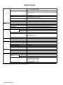
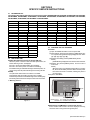
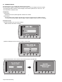
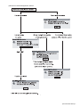
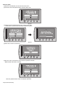
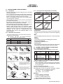
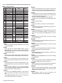
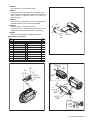
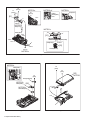
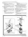
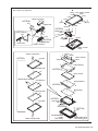
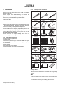
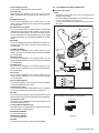
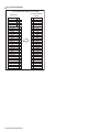
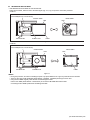
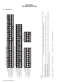
SERVICE MANUAL CAMCORDER SERVICE MANUAL 6 2009 YF307<Rev.003> GZ-HD300AEK, GZ-HD300AER, GZ-HD300AEU, GZ-HD300AEZ, GZ-HD300BEK, GZ-HD300BER, GZ-HD300BEU, GZ-HD300BEZ, GZ-HD300REK, GZ-HD300RER, GZ-HD300REU, GZ-HD300REZ, GZ-HD320BEK, GZ-HD320BER, GZ-HD320BEU, GZ-HD320BEZ GZ-HD300AEKM,GZ-HD300AERM,GZ-HD300AEUM,GZ-HD300AEZM, GZ-HD300BEKM,GZ-HD300BERM,GZ-HD300BEUM,GZ-HD300BEZM, GZ-HD300REKM,GZ-HD300RERM,GZ-HD300REUM,GZ-HD300REZM, [M9H412] GZ-HD320BEKM,GZ-HD320BERM,GZ-HD320BEUM,GZ-HD320BEZM [M9H416] COPYRIGHT © 2009 Victor Company of Japan, Limited Lead free solder used in the board (material : Sn-Ag-Cu, melting point : 219 Centigrade) TABLE OF CONTENTS 1 2 3 4 5 PRECAUTIONS . . . . . . . . . . . . . . . . . . . . . . . . . . . . . . . . . . . . . . . . . . . . . . . . . . . . . . . . . . . . . . . . . . . . . . . 1-3 SPECIFIC SERVICE INSTRUCTIONS . . . . . . . . . . . . . . . . . . . . . . . . . . . . . . . . . . . . . . . . . . . . . . . . . . . . . . 1-5 DISASSEMBLY . . . . . . . . . . . . . . . . . . . . . . . . . . . . . . . . . . . . . . . . . . . . . . . . . . . . . . . . . . . . . . . . . . . . . . . 1-9 ADJUSTMENT . . . . . . . . . . . . . . . . . . . . . . . . . . . . . . . . . . . . . . . . . . . . . . . . . . . . . . . . . . . . . . . . . . . . . . . 1-20 TROUBLE SHOOTING . . . . . . . . . . . . . . . . . . . . . . . . . . . . . . . . . . . . . . . . . . . . . . . . . . . . . . . . . . . . . . . . . 1-24 COPYRIGHT © 2009 Victor Company of Japan, Limited No.YF307<Rev.003> 2009/7 SPECIFICATION General Power supply Power consumption Dimensions (W × H × D) Weight Camera/LCD monitor Connectors Operating temperature Storage temperature Operating humidity Pickup Lens Filter diameter LCD monitor LED Light AV output Video output Audio output HDMI Component output USB Power requirement Output Remote Control Power supply Battery life Operating distance Operating temperature Dimensions (W × H × D) Weight Still image Format Image size Image quality Video Signal format Recording/Playback Video format Audio Recording mode (video) AC Adapter Recording mode (audio) DC 11 V (Using AC adapter) DC 7.2 V (Using battery pack) Approx. 3.5W* * When the LED light is off and the monitor backlight is set to [STANDARD] mode. 53 mm × 68 mm × 113 mm Approx. 325 g Approx. 370 g (incl. battery pack) 0°C to 40°C -20°C to 50°C 35% to 80% 1/4.1" (3,050,000 pixels) progressive CMOS F 1.9 to 3.2, f = 2.9 mm to 58.0 mm, 20:1power zoom lens Ø30.5 mm 2.7" diagonally measured, LCD panel/TFT active matrix system Within 1.5 m (recommended shooting distance) 1.0 V (p-p), 75 Ω 300 mV (rms), 1 kΩ HDMITM (V.1.3 with x.v.ColorTM) Y, Pb, Pr component output Y:1.0V (p-p), 75 Ω Pb/Pr:700 mV (p-p), 75 Ω Mini USB type A and type B,USB 2.0 compliant AC 110 V to 240, 50 Hz/60 Hz DC 11 V, 1 A DC 3 V Approx. 1 year (depending on the frequency of use) Within 5 m 0°C to 40°C 42 mm × 14.5 mm × 91 mm Approx. 30 g (incl. battery) JPEG 1920 × 1080, 1440 × 1080, 640 × 480 FINE/STANDARD 1080/50i MPEG-4 AVC/H.264 Dolby Digital (2ch) UXP: VBR, avarage of 24 Mbps XP: VBR, avarage of 17 Mbps SP: VBR, avarage of 12 Mbps EP: VBR, avarage of 5 Mbps 48 kHz, 256 kbps Design and specifications subject to change without notice. 1-2 (No.YF307<Rev.003>) SECTION 1 PRECAUTIONS 1.1 SAFETY PRECAUTIONS Prior to shipment from the factory, JVC products are strictly inspected to conform with the recognized product safety and electrical codes of the countries in which they are to be sold.However,in order to maintain such compliance, it is equally important to implement the following precautions when a set is being serviced. 1.1.1 Precautions during Servicing (1) Locations requiring special caution are denoted by labels and inscriptions on the cabinet, chassis and certain parts of the product.When performing service, be sure to read and comply with these and other cautionary notices appearing in the operation and service manuals. (2) Parts identified by the symbol and shaded ( ) parts are critical for safety. Replace only with specified part numbers. NOTE : Parts in this category also include those specified to comply with X-ray emission standards for products using cathode ray tubes and those specified for compliance with various regulations regarding spurious radiation emission. (3) Fuse replacement caution notice. Caution for continued protection against fire hazard. Replace only with same type and rated fuse(s) as specified. (4) Use specified internal wiring. Note especially: • Wires covered with PVC tubing • Double insulated wires • High voltage leads (5) Use specified insulating materials for hazardous live parts. Note especially: • Insulation Tape • PVC tubing • Spacers • Insulation sheets for transistors • Barrier (6) When replacing AC primary side components (transformers, power cords, noise blocking capacitors, etc.) wrap ends of wires securely about the terminals before soldering. emission. Consequently, when servicing these products, replace the cathode ray tubes and other parts with only the specified parts. Under no circumstances attempt to modify these circuits.Unauthorized modification can increase the high voltage value and cause X-ray emission from the cathode ray tube. (12) Crimp type wire connectorIn such cases as when replacing the power transformer in sets where the connections between the power cord and power trans former primary lead wires are performed using crimp type connectors, if replacing the connectors is unavoidable, in order to prevent safety hazards, perform carefully and precisely according to the following steps. • Connector part number :E03830-001 • Required tool : Connector crimping tool of the proper type which will not damage insulated parts. • Replacement procedure a) Remove the old connector by cutting the wires at a point close to the connector.Important : Do not reuse a connector (discard it). cut close to connector Fig.1-1-3 b) Strip about 15 mm of the insulation from the ends of the wires. If the wires are stranded, twist the strands to avoid frayed conductors. 15 mm Fig.1-1-4 c) Align the lengths of the wires to be connected. Insert the wires fully into the connector. Metal sleeve Connector Fig.1-1-1 (7) Observe that wires do not contact heat producing parts (heatsinks, oxide metal film resistors, fusible resistors, etc.) (8) Check that replaced wires do not contact sharp edged or pointed parts. (9) When a power cord has been replaced, check that 10-15 kg of force in any direction will not loosen it. Power cord Fig.1-1-5 d) As shown in Fig.1-1-6, use the crimping tool to crimp the metal sleeve at the center position. Be sure to crimp fully to the complete closure of the tool. 1.2 5 2.0 5.5 Fig.1-1-6 e) Check the four points noted in Fig.1-1-7. Not easily pulled free Fig.1-1-2 (10) Also check areas surrounding repaired locations. (11) Products using cathode ray tubes (CRTs)In regard to such products, the cathode ray tubes themselves, the high voltage circuits, and related circuits are specified for compliance with recognized codes pertaining to X-ray Crimping tool Crimped at approx. center of metal sleeve Conductors extended Wire insulation recessed more than 4 mm Fig.1-1-7 (No.YF307<Rev.003>)1-3 1.1.2 Safety Check after Servicing Examine the area surrounding the repaired location for damage or deterioration. Observe that screws, parts and wires have been returned to original positions, Afterwards, perform the following tests and confirm the specified values in order to verify compliance with safety standards. (1) Insulation resistance test Confirm the specified insulation resistance or greater between power cord plug prongs and externally exposed parts of the set (RF terminals, antenna terminals, video and audio input and output terminals, microphone jacks, earphone jacks, etc.).See table 1 below. (2) Dielectric strength test Confirm specified dielectric strength or greater between power cord plug prongs and exposed accessible parts of the set (RF terminals, antenna terminals, video and audio input and output terminals, microphone jacks, earphone jacks, etc.). See Fig.1-1-11 below. (3) Clearance distance When replacing primary circuit components, confirm specified clearance distance (d), (d') between soldered terminals, and between terminals and surrounding metallic parts. See Fig.1-1-11 below. (4) Leakage current test Confirm specified or lower leakage current between earth ground/power cord plug prongs and externally exposed accessible parts (RF terminals, antenna terminals, video and audio input and output terminals, microphone jacks, earphone jacks, etc.). Measuring Method : (Power ON)Insert load Z between earth ground/power cord plug prongs and externally exposed accessible parts. Use an AC voltmeter to measure across both terminals of load Z. See Fig.1-1-9 and following Fig.1-1-12. a Externally exposed accessible part Z A b c V Fig.1-1-9 (5) Grounding (Class 1 model only) Confirm specified or lower grounding impedance between earth pin in AC inlet and externally exposed accessible parts (Video in, Video out, Audio in, Audio out or Fixing screw etc.).Measuring Method: Connect milli ohm meter between earth pin in AC inlet and exposed accessible parts. See Fig.1-1-10 and grounding specifications. d d' Chassis Power cord primary wire Exposed accessible part AC inlet Fig.1-1-8 Earth pin MIlli ohm meter Grounding Specifications Region Grounding Impedance ( Z ) USA & Canada Z 0.1 ohm Europe & Australia Z 0.5 ohm Fig.1-1-10 AC Line Voltage 100 V 100 to 240 V Region Insulation Resistance (R) Japan 110 to 130 V USA & Canada 110 to 130 V 200 to 240 V Europe & Australia R 1M 1 M /500 V DC R R 12 M /500 V DC 10 M /500 V DC Dielectric Strength AC 1 kV 1 minute AC 1.5 kV 1 minute Clearance Distance (d), (d') d, d ' 3 mm d, d ' 4 mm AC 1 kV 1 minute AC 3 kV 1 minute (Class ) AC 1.5 kV 1 minute (Class ) d, d' 3.2 mm d 4 mm d' 8 m m (Power cord) d' 6 m m (Primary wire) Leakage Current (i) a, b, c Fig.1-1-11 AC Line Voltage 100 V Japan 110 to 130 V USA & Canada 110 to 130 V 220 to 240 V Load Z Region Europe & Australia i 1 mA rms Exposed accessible parts i 0.5 mA rms Exposed accessible parts 2 i i 0.7 mA peak 2 mA dc Antenna earth terminals 50 i i 0.7 mA peak 2 mA dc Other terminals 1 0.15 1.5 Fig.1-1-12 NOTE : These tables are unofficial and for reference only. Be sure to confirm the precise values for your particular country and locality. 1-4 (No.YF307<Rev.003>) SECTION 2 SPECIFIC SERVICE INSTRUCTIONS 2.1 DIFFERENCE LIST The following table indicate main different points between models GZ-HD300AEK, GZ-HD300AER, GZ-HD300AEU, GZ-HD300AEZ, GZ-HD300BEK, GZ-HD300BER, GZ-HD300BEU, GZ-HD300BEZ, GZ-HD300REK, GZ-HD300RER, GZ-HD300REU, GZ-HD300REZ, GZ-HD320BEK, GZ-HD320BER, GZ-HD320BEU and GZ-HD320BEZ . MODEL GZ-HD300AEK GZ-HD300AER GZ-HD300AEU GZ-HD300AEZ GZ-HD300BEK GZ-HD300BER GZ-HD300BEU BODY COLOR BLUE BLUE BLUE BLUE BLACK BLACK BLACK HDD 60GB 60GB 60GB 60GB 60GB 60GB 60GB AC ADAPTER AP-V20M AP-V20E AP-V20E AP-V20E AP-V20M AP-V20E AP-V20E AC CORD YES(BS) NO NO NO YES(BS) NO NO MODEL BODY COLOR HDD AC ADAPTER AC CORD MODEL GZ-HD300BEZ GZ-HD300REK GZ-HD300RER GZ-HD300REU GZ-HD300REZ GZ-HD320BEK GZ-HD320BER BLACK RED RED RED RED BLACK BLACK 60GB 60GB 60GB 60GB 60GB 120GB 120GB AP-V20E AP-V20M AP-V20E AP-V20E AP-V20E AP-V20M AP-V20E NO YES(BS) NO NO NO YES(BS) NO GZ-HD320BEU GZ-HD320BEZ BODY COLOR BLACK BLACK HDD 120GB 120GB AP-V20E AP-V20E NO NO AC ADAPTER AC CORD 2.2 REPLACING HDD NOTE1) After HDD replacement, format the HDD first. When the power is turned on after the HDD replacement, the below "Warning screen" is displayed. Be sure to format the HDD following the messages. Be sure to turn off the power once after the formatting. If the HDD recording is started without being turned off the power, normal recording cannot be performed although the recording will start. NOTE2) The picture title data needs to be written in the HDD. Download the data and writing procedure from JS-NET. Note that the picture title is a thumbnail image used in Creating Playlist including Titles and saved in the space where users cannot see. < "Warning screen"> 2.3 CHECKING THE CPU VERSIONS Procedure (1) Open the MONITOR ASSY to turn the power ON. (2) While halfway pressing and holding the [SNAPSHOT] button, repeat touching the buttons [A] and [B] 3 times in order: [A]→[B]→[A]→[B]→[A]→[B]. (3) Release the halfway pressed [SNAPSHOT] button. NOTE) [VERSION INFO] is displayed on the monitor for about 5 seconds. (4) Release the pressed [MENU] button, and the mode is made clear. NOTE) When the mode is not canceled and the button is not operable, disconnect the battery or the DC cable to reset the power. Even when the mode is canceled, resetting the power is recommended. Example:For GZ-HD320 LCD MONITOR VERSION INFO. 0''&61(14/#6*#4&&+5&4+8' #..#9+..$''4#5'& &1;179#0661(14/#6! Model Name Current Ver EEPROM Ver CAMCPU Ver OK Fig.2-2-1 GZ-HD320 1.05 12 0.16 NOTE MENU Button[B] Button[A] NOTECurrent Ver : ELISE CPU VERSION CAMCPU Ver : CAMERA CPU VERSION Fig.2-3-1 NOTE) Display of CAMCPU Ver: Camera CPU Version As the Camera CPU Version cannot be displayed correctly, check the version using Service Support System. (No.YF307<Rev.003>)1-5 2.4 FIRMWARE UPDATE Connecting Everio to a PC via USB cable enables firmware update. Connect a battery, capable of operating for 10 minutes or longer, and an AC adapter to Everio for update. * The following procedure shows the monitor displays of the firmware update from ver. 0.82 to ver. 1.55. * Use Windows XP or Windows Vista. 1.Preparation (1)Preparation Download the firmware update application software from JS-NET. (2)Connection Connect a battery that is capable of operating for 10 minutes or longer and an AC adapter to Everio. * To ensure secure power supply during the update, update is disabled if either of them is not available. 2.Firmware transfer (1) Select "UPDATE" in the main menu of Everio. MENU > BASIC SETTINGS > UPDATE OK MENU Fig.2-4-1 (2)When the displayed current version is an old one, select "YES". OK MENU Fig.2-4-2 (3)Follow the directions on the monitor to connect Everio to the PC via USB cable. OK OK MENU Fig.2-4-3 1-6 (No.YF307<Rev.003>) MENU (4)Execute the downloaded application software. × × × × × Fig.2-4-4 (No.YF307<Rev.003>)1-7 3.Execute update (1)Disconnect the USB cable, and remove Everio from the PC. (2)Check the current and updated versions, and then select "YES". OK MENU Fig.2-4-5 (3)Carefully read and understand the warning, and then select "YES". * It takes about 1 minutes and 30 seconds to complete the update. OK OK MENU Fig.2-4-6 (4)Select "OK", and then re-start Everio. OK MENU Fig.2-4-7 (5)After the re-start, check that the current firmware is updated in UPDATE. MENU > BASIC SETTINGS > UPDATE OK Fig.2-4-8 When the updated firmware version is confirmed, select "NO". 1-8 (No.YF307<Rev.003>) MENU MENU SECTION 3 DISASSEMBLY 3.1 BEFORE ASSEMBLY AND DISASSEMBLY 3.1.1 Precautions • Be sure to disconnect the power supply unit prior to mounting and soldering of parts. • Prior to removing a component part that needs to disconnect its connector(s) and its screw(s), first disconnect the wire(s) from the connector(s), and then remove the screw(s). • When connecting/disconnecting wires, pay enough attention not to damage the connectors. • When inserting the flat wire to the connector, pay attention to the direction of the flat wire. • Be careful in removing the parts to which some spacer or shield is attached for reinforcement or insulation. • When replacing chip parts (especially IC parts), first remove the solder completely to prevent peeling of the pattern. • Tighten screws properly during the procedures. Unless otherwise specified, tighten screws at a torque of 0.088N·m (0.9kgf·cm). However, as this is a required value at the time of production, use the value as a measuring stick when proceeding repair services. (See "SERVICE NOTE" as for tightening torque.) 3.1.4 Tools required for disassembly and assembly CONN. No. CONNECTOR MAIN CN101 MONI BW CN761 40 CN2b MAIN CN103 MINI BW CN762 10 3.1.3 Disconnection of connectors (Wires) Wire Wire Chip IC replacement jig PTS40844-2 Cleaning cloth KSMM-01 Tweezers P-895 Fig.3-1-2 • • PIN No. CN2a Bit YTU94088-003 • Torque driver 3.1.2 Destination of connectors Two kinds of double-arrows in connection tables respectively show kinds of connector/wires. : Flat wire : Wire : Board to board (B-B) : The connector of the side to remove Torque driver YTU94088 • • Be sure to use to fastening the mechanism and exterior parts because those parts must strictly be controlled for tightening torque. Bit This bit is slightly longer than those set in conventional torque drivers. Tweezers To be used for removing and installing parts and wires. Chip IC replacement jig To be used for replacement of IC. Cleaning cloth Recommended cleaning cloth to wipe down the video heads, mechanism (tape transport system), optical lens surface. 3.2 ASSEMBLY AND DISASSEMBLY OF MAIN PARTS 3.2.1 Assembly and disassembly When reassembling, perform the step(s) in reverse order. FPC Connector FPC Connector · Pull both ends of the connector in the arrow direction, remove the lock and disconnect the flat wire. Lock · Extend the locks in the direction of the arrow for unlocking and then pull out the wire. After removing the wire, immediately restore the locks to their original positions because the locks are apt to come off the connector. Wire STEP No. PART Fig. No. POINT NOTE C1 C2-1 C2-2 4(S1a), 3(L1a),CN1a (S2a),2(S2b),3(S2c) 2(SD1a), L2,CN2a,b 2(S8),L8,CN8a - [8] TOP COVER ASSY UPPER ASSY (Inc. VF ASSY, SPEAKER/MONITOR) E.VF UNIT(B/W) NOTE 8 ( 1) ( 2) ( 3) ( 4) ( 5) [1] [2] Lock FPC Connector · Pull the both ends of the board in the direction of the arrow, and remove the Connector. Wire Lock FPC Connector Wire FPC Connector · Extend the locks in the direction of the arrow for unlocking and then pull out the wire. After removing the wire, immediately restore the locks to their original positions because the locks are apt to come off the connector. · Extend the locks in the direction of the arrow for unlocking and then pull out the wire. After removing the wire, immediately restore the locks to their original positions because the locks are apt to come off the connector. B-B Connector B-B Connector B-B Connector · Pull the both ends of the board in the direction of the arrow, and remove the B-B Connector. Fig.3-1-1 (∗1) Order of steps in Procedure When reassembling, preform the step(s) in the reverseorder. These numbers are also used as the identification (location) No. of parts Figures. (∗2) Part to be removed or installed. (∗3) Fig. No. showing Procedure or Part Location. (∗4) Identification of part to be removed, unhooked, unlocked, released, unplugged, unclamped or unsoldered. S = Screw L = Lock, Release, Hook SD = Solder CN = Connector [Example] • 4 (S1a) = Remove 4 S1a screws. • 3 (L1a) = Disengage 3 L1a hooks. • 2 (SD1a) = Unsolder 2 SD1a points. • CN1a = Remove a CN1a connector. (∗5) Adjustment information for installation. (No.YF307<Rev.003>)1-9 3.2.2 Assembly/Dissambly of cabinet parts and electrical parts z Disassembly procedure STEP No. [1] [2] [3] [4] [5] [6] [7] [8] [9] PART NAME Fig. No. 3-2-1 COVER (HINGE) ASSY 3-2-2 HDD COVER ASSY 3-2-3 3-2-4 TOP COVER 3-2-5 HDD 3-2-6 HDD CASE ASSY BKT(O.TOP) 3-2-7 ORNAMENT(TOP) 3-2-8 UPPER ASSY 3-2-9 REAR COVER ASSY [10] 3-2-10 (Inc.REAR BOARD ASSY,ZOOM UNIT) [11] ZOOM UNIT 3-2-11 [12] REAR BOARD ASSY 3-2-12 [13] [14] [15] [16] [17] [18] [19] [20] B.COVER(N)ASSY POINT 3(S1),2(L1a), 2(L1b) 2(S2),2(L2) 4(S3a),S3b,L3a,b,4(L3c) NOTE NOTE1 NOTE2 NOTE3 NOTE4 2(S4a),2(S4b),L14a,2(L4b),L4c CN5 NOTE5a,b,c,d,e,f 3(S6),L6a,b,c 2(S7),L7a,b,2(L7c),L7d L8a,b,c,d,e NOTE8 CN9,S9a,b,L9 NOTE9 CN10a,b,2(S10),L10a,b - S11,L11a,b S12,L12a,b CN13,2(S13),2(L13a) NOTE13 JACK BOARD ASSY 3-2-13 S13,L13b,BKT(HDMI),PLATE(HDMI) 3-2-14 CN14a,b.L14a,b,c NOTE14a,b FRONT ASSY NOTE15 MAIN BOARD ASSY 3-2-15 2(S15),L15,CN15a,b FRAME (PLATE) ASSY 3-2-16 2(S16),L16a,b,c 3-2-17 3(S17),FRAME ASSY NOTE17a,b OP BLOCK ASSY NOTE18 BARRIER UNIT S18a,2(S18b) 3-2-18 HOOD(SCERW) L19a,b 3-2-19 S20,L20a,b,PLATE(MIC) NOTE20 MIC [21] OPE BOARD ASSY [22] SPEAKER [23] MONITOR ASSY S21a,CN21a,2(L21a),L21b, NOTE21a,b,c,d,e CN21b,2(S21b),L21c,d 3-2-21 S22,BKT(SPEAKER),SPACER(SPK) NOTE22a,b 3-2-22 2(S23),L23 NOTE23 3-2-20 NOTE1: When removing the BOTTOM COVER ASSY, open and pull up the COVER (SD). NOTE2: When removing the COVER (HINGE) ASSY, open the MONITOR ASSY, remove the 2 screws, rotate the MONITOR ASSY 90°, tilt it to the rear side, and then pull out the COVER (HINGE) ASSY. NOTE3: Screw No.8 is located under the JACK COVER (USB). Remove or slide the JACK COVER (USB) to remove the screw. NOTE4: Screw No.11 is located under the JACK COVER (AV). Remove or slide the JACK COVER (AV) to remove the screw. NOTE5a: During the procedure, be careful in handling the parts. Pay special attention not to give any external shock to the HDD. NOTE5b: When the HDD is replaced, be sure to refer to Replacing HDD in "SECTION2 SPECIFIC SERVICE INSTRUCTIONS" for the procedure after HDD replacement. NOTE5c: Be careful as the RUBBER SPACERS on both sides are easily come off when the HDD is removed from the main unit. If the RUBBER SPACERS come off, be sure to attach them in the correct direction shown in the figure. 1-10 (No.YF307<Rev.003>) NOTE5d: When connecting the FPC to the connector, insert the FPC straight into the connector. When locking the connector, be careful not to give so much load that it bends the board. NOTE5e: In this procedure, the FPC connected to the HDD connector is not removed. If the FPC is removed due to broken wire, be careful in attachment direction. Be sure to connect the STOPPER side to the HDD. Pay attention as wrong attachment could damage the HDD. NOTE5f: Be careful with the wiring. NOTE8: During the procedure, be careful not to break the parts. NOTE9: Please refer to Fig.3-2-20 and the following procedure for removing the UPPER ASSY. NOTE13: The JACK BOARD ASSY is attached between the PLATE (HDMI) and the BRACKET (HDMI). For replacement, remove the screw (No.28) and disassemble them if necessary. NOTE14a: When attaching the FRONT ASSY, be careful in handling the wire and the FPC. NOTE14b: Please refer to Fig.3-2-18 and the following procedure for removing the FRONT ASSY. NOTE15: When attaching the MAIN BOARD ASSY, be careful in handling the WIRE (CMOS). NOTE17a: Refer to 3.2.3 Assembly/Disambly of [17] OP BLOCK ASSY/ CMOS BOARD ASSY of OP BLOCK ASSY. NOTE17b: When attaching the OP BLOCK ASSY, be careful in handling the WIRE (CMOS). NOTE18: When attaching the BARRIER UNIT, be careful in handling the WIRE (MIC). NOTE20: When attaching the MIC, attach the BARRIER UNIT before handling the WIRE (MIC). (Refer to NOTE 18.) NOTE21a: When removing, remove the screw No.40 first to release the FPC, and then pull out the FPC from the connector. NOTE21b: When removing the OPE BOARD ASSY, release the WIRE (SPK) from the HOOK (L21b) first, and then pull out the WIRE (SPK) from the connector. NOTE21c: When attaching, make sure that the LEVER of the SW(S408) interlocks with the KNOB (SLIDE). NOTE21d: When attaching, be careful with the wiring. NOTE21e: During the procedure, be careful not to damage the parts. When attaching the OPE BOARD ASSY with the MONITOR ASSY closed, be especially careful not to break the SWITCH (S401). NOTE22a: When removing the SPEAKER, be careful in handling as the SPACER (SPK) may come off with the SPEAKER. NOTE22b: When attaching, be careful with the wiring. As the final wiring is performed when attaching the OPE BOARD ASSY, leave the wire as shown in the drawing. [2] a a b b 4 (S2) L2 NOTE23: Refer to 3.2.4 Disassembly of [23] MONITOR ASSY. CN. No. CN5 CN9 CN10a CN10b CN13 CN14a CN14b CN15a CN15b CN21a CN21b PIN No. CONNECTOR MAIN MAIN MAIN MAIN MAIN MAIN MAIN MAIN MAIN OPE OPE CN102 CN101 CN104 CN103 CN114 CN111 CN107 CN105 CN106 CN402 CN401 HDD OPE OPE UNIT REAR JACK LENS BARRIER MIC CMOS OP BLOCK MONITOR SPEAKER - 40 CN401 36/40 - 12 CN602 32/36 - 40 6 4 CN4001 22 - 25 CN703 28/29 2 Fig.3-2-2 9 (S3a) 10 (S3b) 3 (S1) 2 (S1) 1 (S1) NOTE2 5 (S2) z Destination of connectors L1a 8 (S3a) [1] NOTE1 6 (S3a) 7 (S3a) COVER(SD) L1b [3] L3c 10 (S3b) 9 (S3a) L3b L3a 6 (S3a) 7 (S3a) NOTE3 8 (S3a) NOTE3 JACK COVER (USB) Fig.3-2-1 8 (S3a) Fig.3-2-3 (No.YF307<Rev.003>)1-11 NOTE4 16 (S6) JACK COVER (AV) 17 (S6) 15 (S6) 11 (S4a) 14 (S4b) [4] [6] NOTE4 11 (S4a) L4c 13 (S4b) L4a L6a L6b L6c 12 (S4a) L4b 14 (S4b) 12 (S4a) L4a 11 (S4a) Fig.3-2-4 Fig.3-2-6 NOTE5f HDD FPC 18 (S7) NOTE5a,b MAIN BOARD ASSY [5] STOPPER [7] 19 (S7) L7c NOTE5e FPC L7d NOTE5d CN5 L7b L7a NOTE5c RUBBER SPACER Fig.3-2-5 1-12 (No.YF307<Rev.003>) Fig.3-2-7 CN10a L8c NOTE8 [10] L8b L10b CN10b L8a L8d L8e L10a 22 (S10) [8] 23 (S10) Fig.3-2-8 Fig.3-2-10 CN9 24 (S11) [11] L11b 20 (S9a) L9 21 (S9b) CN9 [9] L11a NOTE9 Fig.3-2-9 Fig.3-2-11 (No.YF307<Rev.003>)1-13 L14a L14b L14c NOTE14b [10] [14] CN14a(FPC) L12b CN14b(WIRE) WIRE(MIC) 25 (S12) L12a FPC(LENS BARR.) NOTE14a WIRE(MIC) [12] Fig.3-2-12 FPC(LENS BARR.) Fig.3-2-14 30 (S15) NOTE13 28 (S13) GASKET 29 (S15) [15] L13b NOTE15 CN15a L13a L15 CN15b GASKET [13] CN13 26 (S13a) NOTE15 27 (S13a) CMOS WIRE GASKET Fig.3-2-13 1-14 (No.YF307<Rev.003>) Fig.3-2-15 MAIN PWB NOTE18 38 (S18b) 32 (S16) 31 (S16) 37 (S18b) WIRE(MIC) [16] [18] L16a NOTE18 WIRE(MIC) L16c L16b 36 (S18a) L19a [19] L19b Fig.3-2-16 Fig.3-2-18 NOTE17b 39 (S20) PLATE(MIC) 35 (S17) 33 34 (S17) (S17) [20] NOTE20 WIRE(MIC) L20b FRONT COVER ASSY FRME ASSY L20a NOTE17a [17] 0.118Nm (1.2kgfcm) Fig.3-2-17 Fig.3-2-19 (No.YF307<Rev.003>)1-15 41 (S21b) 42 (S21b) NOTE21a NOTE21b,d 40 (S21a) [21] SW(S401) CN21b WIRE(SPK) L21b FPC a NOTE21e CN21b CN21a NOTE21e SW(S401) NOTE21c WIRE(SPK) L21b L21a [21] L21d SW(S408) L21c SW(S408) a LEVER [21] FPC 40 (S21a) KNOB(SLIDE) NOTE21a Fig.3-2-20 NOTE22b 44 (S23) WIRE(SPK) 45 (S23) BKT(SPACER) NOTE22b WIRE(SPK) [22] NOTE22a SPACER(SPK) L23 Fig.3-2-21 1-16 (No.YF307<Rev.003>) [23] NOTE23 43 (S22) Fig.3-2-22 3.2.3 Assembly/Disambly of [17] OP BLOCK ASSY/CMOS BOARD ASSY zPrecautions (1) Be careful in handling the LENS components. Pay special attention to the surfaces to protect them from stains, dust, or scratches. If the surfaces are soiled with finger prints or other stains, wipe them off with silicon paper, clean chamois leather, or recommended cleaning cloth. zDisassembly of OP BLOCK ASSY / CMOS BOARD ASSY (1) Remove the screw (1), and then remove the SHIELD(CMOS). NOTE17a: When reMmoving the SHIELD(CMOS), be careful in handling as the SHIELD(CMOS) or CMOS BOARD ASSY may be removed together with the HEAT SHEET attached. (2) Remove the 2 screws (2,3), and then remove the CMOS FRAME ASSY. NOTE17b: When removing the CMOS FRAME ASSY, be careful in handling as the CMOS FRAME ASSY may be removed together with the SHEET attached. NOTE17c: The CMOS BOARD ASSY is included in CMOS FRAME ASSY. Replace the CMOS BOARD ASSY as a CMOS FRAME ASSY, not as a single part replacement. zAssembly of OP BLOCK ASSY / CMOS BOARD ASSY (1) The SHEET is set in the OP BLOCK ASSY. (2) Attach the CMOS FRAME ASSY first,so that the SHEET stays in place, and tighten with the 2 screws (2,3). (3) Attach the SHIELD(CMOS) first, and tighten with the screw (1). zReplacement of service repair parts The service repair parts for the OP BLOCK ASSY are as listed below. When replacing parts, be careful not to cut the FPCs or damage any parts by soldering (excessive heat). (1) FOCUS MOTOR UNIT (2) ZOOM MOTOR UNIT (3) AUTO IRIS UNIT NOTE 17d: When replacing the FOCUS MOTOR UNIT or the ZOOM MOTOR UNIT, solder the FPC at a space of about 0.1 mm above the terminal pin. NOTE 17e: The AUTO IRIS UNIT includes the FPC ASSY and two sensors. 1 (S17a) SHIELD(CMOS) 9 (S17b) NOTE17a HEAT SHEET 10 (S17b) 2 (S17b) 8 (S17b) 3 (S17b) NOTE17d AUTO IRIS UNIT SD17b 7 (S17b) 6 (S17b) 4 (S17b) NOTE17c CMOS FRAME ASSY CMOS BOARD ASSY is contained. 5 (S17b) NOTE17b SHEET FOCUS MOTOR UNIT ZOOM MOTOR UNIT OP BLOCK ASSY OP BLOCK ASSY 0.078Nm (0.8kgfcm) 0.147 Nm (1.5kgfcm) Fig.3-2-23 (No.YF307<Rev.003>)1-17 3.2.4 Disassembly of [23] MONITOR ASSY zCAUTIONS (1) During the procedure, be careful in handling the LCD MODULE and other parts. Pay special attention not to damage or stain the monitor screen. If fingerprints are left on the screen, wipe them with clean chamois leather or a cleaning cloth. z Removing MONITOR ASSY (1) Remove the 2 screws (1,2). (2) Turn the HINGE UNIT ASSY 90°, and remove the 2 screws (3,4). (3) Remove the MONI.COVER ASSY by removing the 8 hooks (L23a-h). (4) Release the lock of the connector (CN23a), and remove the HINGE UNIT ASSY by lifting it up. NOTE23a: During the procedure, be careful in handling the FPC. (5) Release the lock of the connectors (CN23b,c), and pull out the FPC. (6) Remove the screw (5), and remove the MONITOR BOARD ASSY . NOTE23b: During the procedure, be careful in handling the FPC. (7) Remove the SHEET (M.REF), LIGHT GUIDE, SHEET(M/ DIFF), and the SHEET(BEF). NOTE23c: When attaching, insert one side of the SHEET (M/ DIFF) under the LCD CASE RIB. NOTE23d: When attaching, insert each tab on both sides of the SHEET (M.REF) into the LCD CASE notch. (8) Remove the LCD CASE, SHEET(COVER), LCD MODULE, SPACER(LCD) and the LCD BKT. NOTE23e: During the procedure, handle the five parts (LCD CASE, SHEET(COVER), LCD MODULE, SPACER(LCD) and the LCD BKT) together. NOTE23f: The SENSOR BOARD ASSY is originally affixed to the MONI.CASE ASSY using jigs and they have structures difficult to replace. If replacement is required, please refer to the NOTE and follow the operation procedure. zAssembly/Disambly of MONITOR CASE ASSY/SENSOR BOARD ASSY Operation procedure • Removing the part which is to be reused (1) Remove the SENSOR BOARD ASSY from the MONI.CASE ASSY by gradually peeling off from the HINGE UNIT ASSY side. NOTE23g: During the procedure, be careful not to break. Prepare the new SENSOR BOARD ASSY and D.FACE TAPE and use them in place of the removed parts. • Completely peel off the remaining tape pieces of the D. FACE TAPE left on the part to be reused (MONI.CASE ASSY). NOTE23h: Make sure that there are no D. FACE TAPE pieces or foreign substances left on the surfaces. If necessary, clean the surfaces using alcohol etc. • Affixing the D. FACE TAPE to the SENSOR BOARD (1) Affix the D. FACE TAPE to the SENSOR BOARD ASSY. NOTE23j: Securely fix the D. FACE TAPE, and then affix the SENSOR BOARD ASSY to the D. FACE TAPE by adjusting the four frames of the SENSOR BOARD ASSY to the 1-18 (No.YF307<Rev.003>) frame of the D. FACE TAPE. Evenly press over the paper backing of each long / short side of the L shape. (2) Peel off the paper backing. NOTE23k: When removing the paper backing, check that there are no foreign substances or air bubbles on the tape. If there are foreign substances etc., completely remove them and continue the affixing procedure. • Affixing the SENSOR BOARD ASSY to the MONI. CASE (1) Affix the SENSOR BOARD ASSY to the MONI. CASE NOTE23m: When affixing, adjust the position of the long side of the L shape to avoid misalignment, and then press evenly. Be sure to press hard for 10 seconds or more on each long/ short side of the L shape for even adhesion. During the procedure, be careful to prevent foreign substances or air bubbles from entering. (2) After the replacement, make sure that there are no broken or deformed parts or any abnormalities. Use the service software for the operation check of the touch sensor sensitivity. NOTE23g,j,k SENSOR BOARD ASSY NOTE23j,k D.FACE TAPE DETACHMENT PAPER NOTE23j,k SENSOR BOARD ASSY D.FACE TAPE Fig.3-2-24 zRemoving HINGE UNIT ASSY (1) Remove the HINGE COVER(U). (2) Remove the HINGE COVER(L). (3) Remove the MAGNET. NOTE23n: During the procedure, be careful in handling the FPC. During the procedure, be careful in handling the MAGNET. When attaching, set the N pole outside as shown in the figure. Be careful when removing as there is no marking. NOTE23p: During the procedure, be careful in handling the FPC. NOTE23q: The FPC, with its connection to the MONITOR BOARD ASSY facing inward, is rolled around the axis (shaft) of the HINGE UNIT ASSY rotation 2.5 rounds (2.5times). 0.118 Nm (1.2kgfcm) 1 (S23a) L23h MONI. COVER ASSY L23c L23g L23e HINGE COVER(U) L23a NOTE23p 3 (S23a) FPC HINGE UNIT L23f L23e 4 (S23a) NOTE23a <NOTE23p,q> FPC L23d b L23k HINGE UNIT ASSY L23n L23m 2 (S23a) L23j L23p CN23c CN23b NOTE23n L23q MAGNET HINGE COVER(L) HINGE UNIT CN23a MONI. COVER ASSY <MONI. CASE SIDE> f NOTE23e b g CN23c 5 (S23b) LCD BKT MONI. BOARD ASSY d c CN20b j e h SPACER(LCD) SHEET(M.REF) m NOTE23d k LIGHT GUIDE (REINFORCED SIDE) LCD MODULE SHEET(M/DIFF) NOTE23c SHEET(BEF) SHEET(COVER) NOTE23c LCD CASE LCD CASE LIB c e g,j f,h m k FPC NOTE23b d NOTE23b FPC SENSOR BOARD ASSY NOTE23f,j <MONI. COVER SIDE> MONI. CASE ASSY NOTE23f,g,h,m Fig.3-2-25 (No.YF307<Rev.003>)1-19 SECTION 4 ADJUSTMENT 4.1 PREPARATION 4.1.1 Precaution Camera system and deck system of this model are specially adjusted by using PC. However, if parts such as the following are replaced, an adjustment is required. The adjustment must be performed in a Service Center equipped with the concerned facilities. • EEP ROM (IC1005 of MAIN board) • OP BLOCK ASSY • MONITOR ASSY In the event of malfunction with electrical circuits, first find a defective portion with the aid of proper test instruments as shown in the following electrical adjustment procedure, and then commence necessary repair/ replacement/adjustment. • In observing chip TP, use IC clips, etc. to avoid any stress. Prior to replacement of chip parts (especially IC), remove the solder completely to prevent peeling of the pattern. • Use a patch cord if necessary. As for a patch cord, see the BOARD INTERCONNECTIONS. • Since connectors are fragile, carefully handle them in disconnecting and connecting the FPC. 4.1.2 Required test equipment • Personal computer (for Windows) • Color TV monitor • Oscilloscope (dual-trace type, observable 100MHz or higher frequency). The one observable 300 MHz or higher frequency is recommended. • Digital voltmeter • DC power supply or AC adapter • Frequency counter (with threshold level adjuster) 4.1.3 Tools required for adjustment Torque Driver Bit Tweezers YTU94088 YTU94088-003 P-895 Chip IC Replacement Jig Cleaning Cloth INF Adjustment Lens PTS40844-2 KSMM-01 YTU92001D INF Adjustment Lens Holder Mini Stand Light Box Assembly YTU94087 YTU93108 YTU93096B Gray Scale Chart Color Bar Chart Focus Chart YTU94133A YTU94133C YTU92001-018 Service Support System Communication Cable YTU94057-117 YTU93111-1 PC Cable Jig Connector Cable Charing Battery Adjuatment Jig QAM0099-005 YTU93106D YTU93112A IDE Adapter IDE Adapter FPC Wire YTU96041 YTU96043 YTU94165-40 • Torque Driver Be sure to use to fastening the mechanism and exterior parts because those parts must strictly be controlled for tightening torque. • Bit This bit is slightly longer than those set in conventional torque drivers. • Tweezers To be used for removing and installing parts and wires. 1-20 (No.YF307<Rev.003>) • Chip IC Replacement Jig To be used for adjustment of the camera system. • Cleaning Cloth Recommended the Cleaning cloth to wipe down the video heads, mechanism (tape transport system), optical lens surface. • INF Adjustment Lens To be used for adjustment of the camera system. For the usage of the INF adjustment lens, refer to the Service Bulletin No. YA-SB-10035. 4.2 JIG CONNECTOR CABLE CONNECTION Connection procedure NOTE • Be sure to turn the power “OFF”, when connecting the JIG CONNECTOR CABLE. If the JIG CONNECTOR CABLE is connected with the power “ON”, communication error may occur. • Remove the 3 screws (1-3), and then remove the B.COVER ASSY. • INF Adjustment Lens Holder 3 To be used together with the Camera stand for operating the Videocamera in the stripped-down condition such as the status without the exterior parts or for using commodities that are not yet conformable to the interchangeable ring. For the usage of the INF lens holder, refer to the Service Bulletin No. YA-SB10035. B.COVER ASSY 1 2 JIG CONNECTOR • Mini Stand To be used together with the INF adjustment lens holder. For the usage of the Mini stand, refer to the Service Bulletin No. YA-SB-10035. • Light Box Assembly To be used for adjustment of the camera system. For the usage of the Light box assembly, refer to the Service Bulletin No. YA-SB-10035. JIG CONNECTOR CABLE SERVICE SUPPORT SYSTEM • Gray Scale Chart To be used for adjustment of the camera system. For the usage of the INF adjustment lens, refer to the Service Bulletin No. YA-SB-10035. RS232C COM PORT MENU • Color Bar Chart To be used for adjustment of the camera system. For the usage of the INF adjustment lens, refer to the Service Bulletin No. YA-SB-10035. • Focus Chart To be used for adjustment of the camera system. For the usage of the INF adjustment lens, refer to the Service Bulletin No. YA-SB-10035. • Service Support System To be used for adjustment with a personal computer. Software can be downloaded also from JS-net. PC CABLE or COMMUNICATION CABLE JIG CONNECTOR PERSONAL COMPUTER COMMUNICATION CABLE BLUE TO AL_2.8V RED TO IF_RX WHITE TO IF_TX BLACK TO GND • Communication Cable Connect the Communication cable between the PC cable and Jig connector cable when performing a PC adjustment. Fig.4-2-1 • PC Cable To be used to connect the Videocamera and a personal computer with each other when a personal computer issued for adjustment. • Jig Connector Cable Connected to JIG CONNECTOR of the main board and used for electrical adjustment, etc. JIG CONNECTOR CABLE [YTU93106D] 30 16 15 1 • Charging Battery Adjustment Jig This Jig is used for the adjustment of the camcorders that have Main Body battery charging function. • IDE Adapter(YTU96041) To be used for HDD test. • IDE Adapter(YTU96043) To be used for HDD test. Fig.4-2-2 • FPC Wire To be used for connecting the HDD to the IDE adapter. (No.YF307<Rev.003>)1-21 Jig connector diagrams JIG CONNECTOR CABLE (YTU93106D) JIG CONN. BOARD (PIN NO.) MAIN CN110 DSP_TDO 1 DSP_TMS 2 17 DSP_TDI XDSPTRST 3 18 XDSPSRST REG_2.83V 4 19 UARXD0 UATXD0 5 20 AL_2.8V IF_TX 6 21 IF_RX NC 7 22 SYS_RSTL OCD_SCL 8 23 CAPSENS_DT NC 9 24 GND OCD_SDA 10 25 GND MVD 11 26 IRU ISSP_DATA 12 27 NC NC 13 28 EXTRG0 DSP_RTCK 14 29 KENTO GND KENTO2 1 2 3 4 5 6 7 8 9 10 11 12 13 14 15 16 17 18 19 20 21 22 23 24 25 26 27 28 29 30 16 DSP_TCK 15 30 Fig.4-2-3 1-22 (No.YF307<Rev.003>) DSP_TDO DSP_TMS XDSPTRST REG_2.83V UATXD0 IF_TX NC OCD_SCL NC OCD_SDA MVD ISSP_DATA NC DSP_RTCK GND DSP_TCK DSP_TDI XDSPSRST UARXD0 AL_2.8V IF_RX SYS_RSTL CAPSENS_DT GND GND IRU NC EXTRG0 KENTO KENTO2 4.3 IDE ADAPTER AND FPC WIRE • IDE ADAPTER and FPC WIRE are used for HDD test. Check with the NOTE, and then refer to the below figure (Fig. 4-3-1, Fig.4-3-2) for the connection procedure. <TYPE-T> FPC WIRE(Parts No.:YTU94165-40) <FRONT SIDE> <BACK SIDE> HDD IDE ADAPTER CONNECTOR HDD LABEL Fig.4-3-1 <TYPE-S> FPC WIRE(Parts No.:YTU94165-40) <FRONT SIDE> <BACK SIDE> HDD IDE ADAPTER CONNECTOR HDD LABEL Fig.4-3-2 <NOTE> • During the procedure, be careful in handling the parts. Pay special attention not to give any external shock to the HDD. • There are two types of IDE ADAPTER (Parts Number: YTU96041, YTU96043). Either type can be used. • Using the FPC WIRE originally used with this unit will damage the HDD. Use the FPC WIRE (Parts Number: YTU94165-40) to connect the IDE ADAPTER and the HDD. Connecting the FPC WIRE upside-down will damage the HDD. (No.YF307<Rev.003>)1-23 1-24 (No.YF307<Rev.003>) 3-2-2 3-2-3 a CABINET PARTS AND ELECTRICAL PARTS(2) 3-2-1 3-2-4 3-2-5 - 3-2-6 a 3-2-7 a 3-2-24 b d 3-2-23 c [20]MONITOR ASSY [23] 1 2 3 4 5 [14]OP BLOCK ASSY/CCD BOARD ASSY [17] 1 2 3 4 5 6 7 8 9 10 a㧦0.088N㨯m (0.9kgf㨯cm) b㧦0.118N㨯m (1.2kgf㨯cm) c㧦0.147N㨯m (1.5kgf㨯cm) d㧦0.078N㨯m (0.8kgf㨯cm) 㧝)㧖and㧖㧖 (This mark shows where to attach the screws) : Do not reuse the screws because the screw lock bond was applied to prevent the screws from loosening. Prepare the specified screws and use them in place of the removed screws. 㧞)Tightening torque for the screws There are setting limits of the torque value for the torque driver. If the value exceeds the setting value, take it as a rough measurement (reference value), and tighten the screw manually. The specified torque value is a recommended value of the initial assembly. Therefore, set the value below the specified torque value in the assembling procedure. Be careful not to break either the screws or the screw holes. NOTE: Symbol No. Removing order of screw Place to stick screw Reference drawing (Fig.No.) Screw tightening torque 3-2-10 3-2-11 3-2-12 a [9] [10] [11] [12] 20 21 22 23 24 25 3-2-8 3-2-9 - CABINET PARTS AND ELECTRICAL PARTS(1) [1] [2] [3] [4] [5] [6] [7] [8] 1 2 3 4 5 6 7 8 9 10 11 12 13 14 - 15 16 17 18 19 - 5.1 Symbol No. [13] [14] [15] [16] [17] [18] [19] [20] [21] [22] [23] Removing order of screw 26 27 28 - 29 30 31 32 33 34 35 36 37 38 - 39 40 41 42 43 44 45 Place to stick screw Reference drawing (Fig.No.) 3-2-14 3-2-15 3-2-16 3-2-19 3-2-21 3-2-22 3-2-13 3-2-17 3-2-18 3-2-20 a a a a Screw tightening torque b - Symbol No. Removing order of screw Place to stick screw Reference drawing (Fig.No.) Screw tightening torque SECTION 5 TROUBLE SHOOTING SERVICE NOTE Victor Company of Japan, Limited Camcorder Division 12, 3-chome, Moriya-cho, Kanagawa-ku, Yokohama-city, Kanagawa-prefecture, 221-8528, Japan (No.YF307<Rev.003>) Printed in Japan VSE