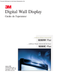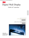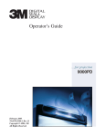
1
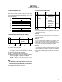
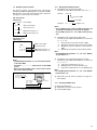
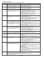
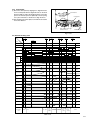
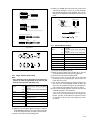
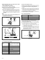
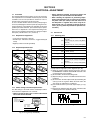
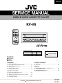
KV-V8
SERVICE MANUAL
MOBILE VIDEO CASSETTE PLAYER
KV-V8
Comparison table
Item
Signal system
Area Continental
KV-V8E
KV-V8J
PAL
NTSC
Europe
U.S.A.
Area Suffix
E
J
Continental Europe
North America
Contents
q Specifications
q CAUTION
q Instructions
1. DISASSEMBLY
1.1 Disassembly flow chart . . . . . . . . . . . . . . . . . . . . . . . . . . . . . . . . . . . . . .
1.2 How to read the disassembly and assembly . . . . . . . . . . . . . . . . .
1.3 Disassembly/assembly method . . . . . . . . . . . . . . . . . . . . . . . . . . . . . .
1.4 Service position . . . . . . . . . . . . . . . . . . . . . . . . . . . . . . . . . . . . . . . . . . . . . .
1.5 Mechanism service mode . . . . . . . . . . . . . . . . . . . . . . . . . . . . . . . . . . .
1.6 Emergency display function . . . . . . . . . . . . . . . . . . . . . . . . . . . . . . . . .
1-1
1-1
1-1
1-4
1-4
1-5
2. MECHANISM ADJUSTMENT
. . . . . . . . . . . . . . . . . . . . . 2-1
2.1 Before starting repair and adjustment
2.2 Replacement of major parts . . . . . . . . . . . . . . . . . . . . . . . . . . . . . . . . . 2-4
2.3 Installation of major parts (Mechanism phase alignment) . . . . . 2-9
2.4 Mechanism timing chart . . . . . . . . . . . . . . . . . . . . . . . . . . . . . . . . . . . . 2-11
2.5 Compatibility adjustment . . . . . . . . . . . . . . . . . . . . . . . . . . . . . . . . . . . 2-12
COPYRIGHT
3. ELECTRICAL ADJUSTMENT
3.1 Precaution . . . . . . . . . . . . . . . . . . . . . . . . . . . . . . . . . . . . . . . . . . . . . . . . . . . . 3-1
3.2 Servo circuit . . . . . . . . . . . . . . . . . . . . . . . . . . . . . . . . . . . . . . . . . . . . . . . . . . 3-1
5. PARTS LIST
5.1 PACKING AND ACCESSORY ASSEMBLY <M1> . . . . . . . . . . .
5.2 FINAL ASSEMBLY <M2> . . . . . . . . . . . . . . . . . . . . . . . . . . . . . . . . . . .
5.3 MECHANISM ASSEMBLY <M4> . . . . . . . . . . . . . . . . . . . . . . . . . . . .
5.4 ELECTRICAL PARTS LIST . . . . . . . . . . . . . . . . . . . . . . . . . . . . . . . . . . .
2001 VICTOR COMPANY OF JAPAN, LTD.
5-1
5-2
5-4
5-6
No.49625
Feb. 2001
Specificatios (KV-V8J)
General
•Power supply
•Dimensions
•Mass
•Allowable working temperature
•Allowable relative humidity
•Allowable conservation temperature
: DC12 V (11V-16V allowable)Negative ground
: 259 mm x 94 mm x 270 mm (10-1/4"x 3-3/4"x 10-11/16")
(width x height x depth)
: 3.2 kg (7.1 lbs)
: 0 °C to +40 °C (32 °F to104 °F)
: 35%to 80%
: -20 °C to +60 °C (-4 °F to 140 °F)
Video
•Playback system
•Video signal
: VHS format,Hi-Fi 4-heads helical scan
: VHS NTSC standard
Audio
•Playback system
•Audio track
•Remote control unit
: VHS stereo Hi-Fi audio
: 2 Hi-Fi audio channels and 1 normal audio channel
: A code
(A code and B code are switchable automatically in the main unit.)
Design and specifications subject to change without notice.
Specificatios (KV-V8E)
General
•Power supply
•Dimensions
•Mass
•Allowable working temperature
•Allowable relative humidity
•Allowable conservation temperature
: DC12 V (11V-16V allowable)Negative ground
: 259 mm x 94 mm x 270 mm
(width x height x depth)
: 3.2 kg
: 0 °C to +40 °C
: 35%to 80%
: -20 °C to +60 °C
Video
•Playback system
•Video signal
: VHS format,Hi-Fi 4-heads helical scan
: VHS PAL standard
Audio
•Playback system
•Audio track
•Remote control unit
: VHS stereo Hi-Fi audio
: 2 Hi-Fi audio channels and 1 normal audio channel
: A code
(A code and B code are switchable automatically in the main unit.)
Design and specifications subject to change without notice.
! CAUTION Burrs formed during molding may be left over on some parts of the chassis. Therefore,
pay attention to such burrs in the case of preforming repair of this system.
SECTION 1
DISASSEMBLY
1.1 Disassembly flow chart
1.3 Disassembly/assembly method
This flowchart lists the disassembling steps for the cabinet
parts and P.C. boards in order to gain access to item(s)
to be serviced. When reassembling, perform the step(s) in
reverse order. Bend, route and dress the flat cables as they
were originally laid.
Step/
Part Name
Loc No.
[1] Top cover
[2] SW board assembly,
Front panel assembly
[3]
[1]
Top cover
[2]
SW board assembly, Front panel assembly
[3]
Cassette housing assembly
[4]
Drum assembly
[5]
Mechanism assembly
[6]
Main board assembly
[4]
[5]
[6]
<Note 2a>
• Be careful not to damage the connector and wire etc. during connection and disconnection. When connecting the wire to the connector, be
careful with the wire direction.
1.2 How to read the disassembly and assembly
<Example>
Step/
Part Name
Loc No.
[1] Top cover
Bracket
(1)
(2)
Fig.
Point
Note
No.
D1 4(S1a),(S1b),3(L1a), <Note 1>
2(SD1a), (P1a),
CN1(WR1a),
2(S1c)
(3)
(4)
Fig.
Point
Note
No.
D1 2(S1a), (S1b), 2(S1c)
D2 2(S2a), (WR2a), stay <Note 2a>
------------------4(L2a), 3(L2b),
<Note 2b>
CN3006(WR2b)
Cassette housing
D3a, 2(S3a), 2(L3a)
<Note 3a>
assembly
D3b
Drum assembly
D4 CN1(WR4a),
<Note 2a>
CN1(WR4b),
(S4a), (S4b), (S4c)
Mechanism assembly D5 CN1(WR5a),
<Note 2a>
CN3003(WR5b),
<Note 5a>
CN3005(WR5c),
2(S5a), (S5b),
2(L5a)
Main board assembly D6 (S6a), (S6b)
(5)
(1) Order of steps in Procedure
When reassembling, perform the step(s) in the reverse order.
These numbers are also used as the identification (location) No.
of parts Figures.
(2) Part name to be removed or installed.
(3) Fig. No. showing procedure or part location.
(4) Identification of part to be removed, unhooked, unlocked,
released, unplugged, unclamped or unsoldered.
P= Spring, W= Washer, S= Screw, L= Locking tab, SD= Solder,
CN**(WR**)= Remove the wire (WR**) from the connector
(CN**).
<Note 2b>
• When reattaching the Front panel assembly, make sure that the door
opener “a” of the Cassette housing assembly is lowered in position
prior to the reinstallation.
<Note 3a>
• When installing the Cassette housing assembly, make sure that the
Control cam and the Main deck alignment holes are aligned. if they
are not, rotate the Loading motor belt to the front align the holes.
• When installing the Cassette housing assembly, be careful not to damage the parts of the Main board and Mechanism assemblies.
<Note 5a>
• When removing the Mechanism assembly only, unhook the two spacers
connecting it with the Main board assembly with pliers from the back
side of the Main board assembly first, and then remove the Mechanism assembly.
• When reattaching the Mechanism assembly to the Main board assembly, take care not to damage the sensors on the Main board assembly.
Note:
• The bracketed ( ) WR of the connector symbol are assigned nos. in priority order and do not correspond to
those on the spare parts list.
(5) Adjustment information for installation
1-1
(S3a)
(S3a)
(S1c)
[1] Top cover
(S1b)
(L3a)
(S1c)
(S1a)
[3] Cassette
housing
assembly
Switch lever
A
(L3a)
(S1a)
A
REC safety switch
<Note 3a>
Fig. D3a
Fig. D1
(S2a)
Stay
(S2a)
[2] SW board
assembly
WR2a
Loading motor belt
G
Rear side
Pinch plate
WR2b
Foil side
<Note 2a>
(L2a)
CN3006
[2] Front panel
assembly
Hole align
with hole in
deck
<Note 3a>
Door opener
“a” <Note 2b>
(L2a)
Detail “G”
Control cam
SW board
WR2a
(L2b)
WR2b
Chassis
Main board CN3006
Fig. D2
1-2
Front
board
Fig. D3b
Note:
When installing the Drum assembly, secure the screws (S4a – S4c)
in the order of a , b , c .
Not used
Inertia plate
(S6b)
(S6a)
[6] Main board
assembly
(L5b)
(S4a)
WR4a
Supporting
tape side
<Note 2a>
WR4b
Supporting
tape side
<Note 2a>
(S4c)
CN1
Not used
Cleaner assembly
<Note 5>
(S4b)
[4]
Drum
assembly
(L5a)
<d>
CN1
<e>
Not used
Fig. D6
Fig. D4
(S5a)
Not used
WR4
WR5a
(S5b)
WR5c
CN1
[5] Mechanism
assembly
WR5b
Red line:
CN3003 pin1
CN3005
CN3003
(L5a)
Spacer
<Note5a>
Fig. D5
1-3
1.4 Service position
This unit has been designed so that the Mechanism and Main
board assemblies can be removed together from the chassis assembly. Before diagnosing or servicing the circuit
boards, take out the major parts from the chassis assembly.
Main board assembly
TP4001 TP2253
CTL.P
A FM
TP111
D.FF
TP106
PB FM
1.4.1 How to set the "Service position”
(1) Refer to the disassembly procedure and perform disassembly of the major parts before removing the Cassette
housing assembly.
(2) Remove the combined Cassette housing, Mechanism
and Main board assemblies.
(3) Connect the wires and connectors of the major parts that
have been removed in step (1). (Refer to Fig. 1-4-1a.)
(4) Place the combined Mechanism and Main board assemblies upside down.
(5) Insert the power cord plug into the power outlet and then
proceed with the diagnostics and servicing of the board
assembly.
Notes:
• Before inserting the power cord plug into the power
outlet, make sure that none of the electrical parts are
able to short-circuit between the workbench and the
board assembly
• For the disassembly procadure of the major parts and
details of the precautions to be taken, see “1.3 Disassembly/assembly method”.
• If there are wire connections from the Main board and
Mechanism assemblies to the other major parts, be
sure to remove them first before performing step (2).
• When carrying out diagnosis and repair of the Main
board assembly in the “Service position”, be sure to
ground both the Main board and Mechanism assemblies. If they are improperly grounded, there may be
noise on the playback picture or FDP counter display
may move even when the mechanism is kept in an inoperative status.
• In order diagnose the playback or recording of the cassette tape, set the Mechanism assembly to the required
mode before placing it upside down. If the mechanism
mode is changed (including ejection) while it is in an
upside down position the tape inside may be damaged.
• When checking the operation or performing adjustments to the VCP main unit, it is necessary to connect
the power cable (Car Cable) to the VCP main unit so
that DC power is supplied. Also, when using the remote control unit, it is required to connect the IR receiver. (by using either the provided or optional accessories)
1-4
SW board
assembly
CN3006
CP5001 CP5002
Front board
assembly
CN7001
TP7001
MECHA TEST
TP7002
GND
Fig. 1-4-1a
1.5 Mechanism service mode
This model has a unique function to enter the mechanism
into every operation mode without loading of any cassette
tape. This function is called the "Mechanism service mode".
1.5.1 How to set the "Mechanism service mode"
(1) Unplug the power cord plug from the power outlet.
(2) Remove the Front panel assembly and Cassette housing assembly. (Take care not to pull the flat wire.)
(3) Connect TPGND and TP7001(TEST) on the Front board
assembly with a jump wire.
(4) Insert the power cord plug into the power outlet.
(5) Turn on the power. When the loading has completed,
the mechanism enters the desired mode.
1.6.1
1.6 Emergency display function
This unit has a function for storing the history of the past two
emergencies (EMG) and displaying them on each FDP (or OSD).
With the status of the VCR and mechanism at the moment an
emergency occurred can also be confirmed.
Displaying the EMG information
(1) Transmit the code “59” from the Jig RCU.
The FDP shows the EMG content in the form of “E: * * : * * ”.
Example 1
E : 01 : 03
Previous EMG
FDP display model
[FDP display]
Latest EMG
0 : 00 : 00
Normal display
E: * * : * *
EMG content display
(E:Latest:Previous)
*1: *2 : 34
EMG detail information <1>
*5: *6 : *7
EMG detail information <2>
Example 2
E : –– : ––
No EMG record
Notes:
• For the OSD display model, all EMG information are
showed by transmitting first code from the Jig RCU.
• For the EMG content, see “1.6.3 EMG content description”.
(2) Transmit the code “59” from the Jig RCU again.
The FDP shows the EMG detail information <1> in the form
of “ * 1 : * 2 : 34 ”.
OSD display model
[OSD display]
* 1 : Deck operation mode at the moment of EMG
* 2 : Mechanism operation mode at the moment of EMG
3– : Mechanism sensor information at the moment of
EMG
–4 : Mechanism mode position at the moment of EMG
EMG content display
(E:Latest:Previous)
EMG
E: * * : * *
*1: *2 : 34
*5: *6 : *7
EMG detail information <1>
EMG detail information <2>
Notes:
• The EMG detail information <1><2> show the information
on the latest EMG.
It becomes “ – – : – – : – –” when there is no latest EMG
record.
• When using the Jig RCU, set its custom code to match
the custom code of the VCR.
Jig RCU
[Data transmitting method]
Depress the “ ” ( 3 ) button
after the data code is set.
CUSTOM CODE
43: A CODE
53: B CODE
DATA CODE
Fig. 1-6a Jig RCU [PTU94023B]
Note:
• For the EMG detail information <1> , see “1.6.4 EMG detail information <1> ”.
(3) Transmit the code “59” from the Jig RCU once again.
The FDP shows the EMG detail information <2> in the form
of “ * 5 : * 6 : * 7 ”.
* 5 : Type of the cassette tape in use <1> .
* 6 : Winding position of the cassette tape in use
* 7 : Type of the cassette tape in use <2> (Winding area)
Note:
• For the EMG detail information <2> , see “1.6.5 EMG detail information <2>”.
(4) Transmit the code “59” from the Jig RCU once again to reset the display.
INITIAL MODE
1.6.2
Clearing the EMG history
(1) Display the EMG history.
(2) Transmit the code “36” from the Jig RCU.
(3) Reset the EMG display.
1-5
1.6.3
EMG content description
Note: EMG contents “E08/E09” are for the model with Dynamic Drum (DD).
FDP
CONTENT
E01: Loading EMG
When the mechanism mode cannot be changed to another mode even when the loading motor has rotated
for more than 4 seconds in the loading direction, [E:01]
is identified and the power is turned off.
1. The mechanism is locked in the middle of mode transition.
2. The mechanism is locked at the loading end due to the encoder position
reading error during mode transition.
3. Power is not supplied to the loading MDA.
E02: Unloading EMG When the mechanism mode cannot be changed to another mode even when the loading motor has rotated
for more than 4 seconds in the unloading direction, [E:02]
is identified and the power is turned off.
1. The mechanism is locked in the middle of mode transition.
2. The mechanism is locked at the unloading end due to the encoder position reading error during mode transition.
3. Power is not supplied to the loading MDA.
E03: Take Up Reel
Pulse EMG
When the take-up reel pulse has not been generated for
more than 4 seconds in the capstan rotating mode, [E:03]
is identified, the pinch rollers are turned off and stopped,
and the power is turned off. However, the reel EMG is
not detected in STILL/SLOW modes.
1. The take-up reel pulse is not generated in the FWD transport modes (PLAY/
FWD SEARCH/FF, etc.) because;
1) The idler gear is not meshed with the take-up reel gear;
2) The idler gear is meshed with the take-up reel gear, but incapable of winding due to too large mechanical load (abnormal tension);
3) The take-up reel sensor does not output the FG pulse.
2. The supply reel pulse is not generated in the REV transport modes (REV
SEARCH/REW, etc.) because;
1) The idler gear is not meshed with the supply reel gear.
2) The idler gear is meshed with the supply reel gear, but incapable of winding due to too large a mechanical load (abnormal tension);
3) The supply reel sensor does not output the FG pulse.
3. Power is not supplied to the reel sensors.
E04: Drum FG
EMG
When the drum FG pulse has not been input for more
than 3 seconds in the drum rotating mode, [E:04] is identified, the pinch rollers are turned off and stopped, and
the power is turned off.
1. The drum could not start or the drum rotation has stopped due to too large
a load on the tape, because;
1) The tape tension is abnormally high;
2) The tape is damaged or a foreign object (grease, etc.) adheres to the tape.
2. The drum FG pulse did not reach the System controller CPU because;
1) The signal circuit is disconnected in the middle;
2) The FG pulse generator (hall device) of the drum is faulty.
3. The drum control voltage (DRUM CTL V) is not supplied to the MDA.
4. Power is not supplied to the drum MDA.
E05: Cassette Eject When the eject operation does not complete in 3 seconds after the start, [E:05] is identified, the pinch rollers
EMG
are turned off and stopped, and the power is turned off.
When the cassette insertion operation does not complete
in 3 seconds after the start, the cassette is ejected. In
addition, when the operation does not complete within
3 seconds after the start, [E:05] is also identified and the
power is turned off immediately.
1. The cassette cannot be ejected due to a failure in the drive mechanism of
the housing.
2. When the housing load increases during ejection, the loading motor is
stopped because of lack of headroom in its drive torque.
Housing load increasing factors: Temperature environment (low temperature, etc.), mechanism wear or failure.
3. The sensor/switch for detecting the end of ejection are not functioning normally.
4. The loading motor drive voltage is lower than specified or power is not supplied to the motor (MDA).
5. When the user attempted to eject a cassette, a foreign object (or perhaps
the user's hand) was caught in the opening of the housing.
E06: Capstan FG
EMG
When the capstan FG pulse has not been generated for
more than 1 second in the capstan rotating mode, [E:06]
is identified, the pinch rollers are turned off and stopped,
and the power is turned off.However, the capstan EMG
is not detected in STILL/SLOW/FF/REW modes.
1. The capstan could not start or the capstan rotation has stopped due to too
large a load on the tape, because;
1) The tape tension is abnormally high (mechanical lock);
2) The tape is damaged or a foreign object (grease, etc.) is adhered to the
tape (occurrence of tape entangling, etc.).
2. The capstan FG pulse did not reach the System controller CPU because;
1) The signal circuit is disconnected in the middle;
2) The FG pulse generator (MR device) of the capstans is faulty.
3. The capstan control voltage (CAPSTAN CTL V) is not supplied to the MDA.
4. Power is not supplied to the capstan MDA.
E07: SW Power
Short-Circuit
EMG
When short-circuiting of the SW power supply with GND
has lasted for 0.5 second or more, [E:07] is identified,
all the motors are stopped and the power is turned off.
1. The SW 5 V power supply circuit is shorted with GND.
2. The SW 12 V power supply circuit is shorted with GND.
E08: DD Initialized
(Absolute
Position
Sensor)
EMG
When DD tilting does not complete in 4 seconds, [E:08]
is identified, the tilt motor is stopped and the power is
turned off.
1. The absolute value sensor is defective. (The soldered parts have separated.)
2. The pull-up resistor at the absolute sensor output is defective. (The soldered parts
have separated.)
3. Contact failure or soldering failure of the pins of the connector (board-to-board) to the
absolute value sensor.
4. The absolute value sensor data is not sent to the System Controller CPU.
When the DD FG pulse is not generated within 2.5 seconds, [E:09] is identified, the tilt motor is stopped and
the power is turned off.
1. The FG sensor is defective. (The soldered parts have separated.)
2. The pull-up resistor at the FG sensor output is defective. (The soldered parts have
separated.)
3. Contact failure or soldering failure of the pins of the connector (board-to-board) to the FG sensor.
4. The power to the sensor is not supplied. (Connection failure/soldering failure)
5. The FG pulse is not sent to the System Controller CPU.
6. The tilt motor is defective. (The soldered parts have separated.)
7. The drive power to the tilt motor is not supplied. (Connection failure/soldering failure)
8. The tilt motor drive MDA - IC is defective.
9. Auto-recovery of the DD tilting cannot take place due to overrun.
When the supply reel pulse has not been generated for
more than 10 seconds in the capstan rotating mode,
[E:0A] is identified and the cassette is ejected (but the
power is not turned off). However, note that the reel EMG
is not detected in the SLOW/STILL mode.
1. The supply reel pulse is not generated in the FWD transport mode (PLAY/
FWD SEARCH/FF, etc.) because;
1) PLAY/FWD or SEARCH/FF is started while the tape in the inserted cassette is cut in the middle;
2) A mechanical factor caused tape slack inside and outside the supply
reel side of the cassette shell. In this case, the supply reel will not rotate
until the tape slack is removed by the FWD transport, so the pulse is not
generated until then;
3) The FG pulse output from the supply reel sensor is absent.
2. The take-up reel pulse is not generated in the REV transport mode (REV
SEARCH/REW, etc.).
1) REV SEARCH/REW is started when the tape in the inserted cassette
has been cut in the middle;
2) A mechanical factor caused tape slack inside and outside the take-up
reel side of the cassette shell. In this case, the supply reel will not rotate
until the tape slack is removed by the REV transport, so the pulse will
not be generated until that time;
3) The FG pulse output from the take-up reel sensor is absent.
3. The power to a reel sensor is not supplied.
E09: DD FG EMG
E0A:Supply Reel
Pulse EMG
CAUSE
Presupposing the presence of the control pulse output in the PLAY mode, when the value obtained by mixing the two V.FM output
EC1 or EU1:
Head clog warning channels (without regard to the A.FM output) has remained below a certain threshold level for more than 10 seconds, [E:C1] or [E:U1]
is identified and recorded in the emergency history. During the period in which a head clog is detected, the FDP and OSD repeat the
“3-second warning display” and “7-second noise picture display” alternately.
EMG code : “E:C1” or “E:U1” / FDP : “U:01” / OSD : “Try cleaning tape.” or “Use cleaning cassette.”
The head clog warning is reset when the above-mentioned threshold has been exceeded for more than 2 seconds or the mode is
changed to another mode than PLAY.
Table 1-6-3a
1-6
1.6.4
EMG detail information <1>
The status (electrical operation mode) of the VCR and the status (mechanism operation mode/sensor information) of the
mechanism in the latest EMG can be confirmed based on the
figure in EMG detail information <1> .
[FDP/OSD display]
* 1 : * 2 : 34
*1 :
*2 :
3– :
–4 :
Deck operation mode at the moment of EMG
Mechanism operation mode at the moment of EMG
Mechanism sensor information at the moment of EMG
Mechanism mode position at the moment of EMG
Note:
• For EMG detailed information <1>, the content of the code
that is shown on the FDP (or OSD) differs depending on
the parts number of the system control microprocessor
(IC3001) of the VCR. The system control microprocessor
parts number starts with two letters, refer these to the corresponding table.
* 1 : Deck operation mode
[Common table of MN*, HD* and M3*]
Display
Deck operation mode
MN*/M3* HD*
00
Mechanism being initialized
01
00 STOP with pinch roller pressure off (or tape present with P.OFF)
02
01 STOP with pinch roller pressure on
03
POWER OFF as a result of EMG
04
04 PLAY
0C
0E REC
10
11 Cassette ejected
20
22 FF
21
Tape fully loaded, START sensor ON, short FF
22
Cassette identification FWD SEARCH before transition to FF (SP
x7-speed)
24
26 FWD SEARCH (variable speed) including x2-speed
2C
2E INSERT REC
40
43 REW
42
Cassette identification REV SEARCH before transition to REW (SP
x7-speed)
44
47 REV SEARCH (variable speed)
4C
4C AUDIO DUB
6C
6E INSERT REC (VIDEO + AUDIO)
84
84 FWD STILL / SLOW
85
85 REV STILL / SLOW
8C
8F REC PAUSE
8D
Back spacing
8E
Forward spacing (FWD transport mode with BEST function)
AC
AF INSERT REC PAUSE
AD
INSERT REC back spacing
CC
CD AUDIO DUB PAUSE
CD
AUDIO DUB back spacing
EC
EF INSERT REC (VIDEO + AUDIO) PAUSE
ED
INSERT REC (VIDEO + AUDIO) back spacing
* 2 : Mechanism operation mode
[Common table of MN* and M3*]
Display
MN* M3*
00
00
02
02
04
04
06
06
08
08
0A
0C
0E
10
12
14
0A
0C
0E
10
12
14
16
16
18
18
1A
1C
1E
20
22
24
26
28
2A
2C
2E
80
1A
1C
1E
20
22
24
26
28
2A
2C
2E
30
80
Mechanism operation mode
Command standby (Status without executing command)
POWER OFF by EMG occurrence
Moving to the adjacent position in the LOAD direction
Moving to the adjacent position in the UNLOAD direction
Cassette ejection being executed / Cassette housing ejection being
executed
Mode transition to STOP with cassette ejection end
Cassette insertion being executed
Tape being loaded
Tape being unloaded
Mode transition to STOP with pinch roller compression ON
Mode transition to STOP with pinch roller compression OFF
Mode transition to STOP with pinch roller compression OFF as a result
of POWER OFF
Mode transition to STOP with pinch roller compression ON as a result
of POWER ON
Mode transition to PLAY
Mode transition to FWD SEARCH
Mode transition to REC
Mode transition to FWD STILL / SLOW
Mode transition to REV STILL / SLOW
Mode transition to REV SEARCH
Mode transition from FF / REW to STOP
Mode transition to FF
Mode transition to REW
4 sec. of REV as a result of END sensor going ON during loading
Short FF / REV as a result of END sensor going ON during unloading
Mechanism position being corrected due to overrun
Mechanism in initial position (Dummy command)
[Table of HD*]
Display
Mechanism operation mode
00
01
02
04
05
0E
11
22
26
2E
43
47
4C
6E
84
85
8F
AF
C7
CD
EF
F0
F1
F2
F3
F4
STOP with pinch roller pressure off
STOP with pinch roller pressure on
U/L STOP (or tape being loaded)
PLAY
PLAY (x1-speed playback using JOG)
REC
Cassette ejected
FF
FWD SEARCH (variable speed) including x2-speed
INSERT REC
REW
REV SEARCH
AUDIO DUB
INSERT REC (VIDEO + AUDIO)
FWD STILL/SLOW
REV STILL/SLOW
REC PAUSE
INSERT REC PAUSE
REV SEARCH (x1-speed reverse playback using JOG)
AUDIO DUB PAUSE
INSERT REC (VIDEO + AUDIO) PAUSE
Mechanism being initialized
POWER OFF as a result of EMG
Cassette being inserted
Cassette being ejected
Transition from STOP with pinch roller pressure on to STOP with pinch
roller pressure off
Transition from STOP with pinch roller pressure on to PLAY
Transition from STOP with pinch roller pressure on to REC
Cassette type detection SEARCH before FF/REW is being executed
Tape being unloaded
Transition from STOP with pinch roller pressure off to STOP with pinch
roller pressure on
Transition from STOP with pinch roller pressure off to FF/REW
Transition from STOP with pinch roller pressure off to REC.P (T.REC,etc.)
Transition from STOP with pinch roller pressure off to cassette type detection SEARCH
Short REV being executed after END sensor on during unloading
Tension loosening being executed after tape loading (STOP with pinch
roller pressure on)
F5
F6
F7
F8
F9
FA
FB
FC
FD
FE
1-7
3– : Mechanism sensor information
[Common table of MN*, HD* and M3*]
Mechanism sensor information
Display MN* / HD*
S-VHS SW
0123456789ABCDEF-
VHS
VHS
VHS
VHS
VHS
VHS
VHS
VHS
S-VHS
S-VHS
S-VHS
S-VHS
S-VHS
S-VHS
S-VHS
S-VHS
M3*
CASS SW
REC safety
SW
Start
sensor
End
sensor
Cassette insertion
Cassette insertion
Cassette insertion
Cassette insertion
Cassette insertion
Cassette insertion
Cassette insertion
Cassette insertion
Cassette ejection
Cassette ejection
Cassette ejection
Cassette ejection
Cassette ejection
Cassette ejection
Cassette ejection
Cassette ejection
Tab broken
Tab broken
Tab broken
Tab broken
Tab present
Tab present
Tab present
Tab present
Tab broken
Tab broken
Tab broken
Tab broken
Tab present
Tab present
Tab present
Tab present
ON
ON
OFF
OFF
ON
ON
OFF
OFF
ON
ON
OFF
OFF
ON
ON
OFF
OFF
ON
OFF
ON
OFF
ON
OFF
ON
OFF
ON
OFF
ON
OFF
ON
OFF
ON
OFF
–4 : Mechanism mode position
[Common table of MN*, HD* and M3*]
Display
Mechanism mode position
MN* HD* M3*
-0
-1
-2
-3
-4
-7
-0
-7
-1
-7
-0
-1
-2
-3
-4
-5
-2
-5
-6
-7
-8
-7
-3
-7
-6
-F
-F
-9
-A
-4
-7
-F
-E
-B
-C
-D
-E
-F
-5
-7
-6
-7
-6
-D
-C
-B
-A
-9
-8
-7
Initial value
EJECT position
EJECT position (Cassette housing drive mode)
Housing operating
Between EJECT and U / L STOP
U / L STOP position
Guide arm drive position
Tape being loaded / unloaded (When the pole base is
located on the front side of the position just beside the
drum)
Tape being loaded / unloaded (When the pole base is
located on the rear side of the position just beside the
drum)
Pole base compressed position
FF / REW position
Between FF / REW and STOP with pinch roller compression ON
STOP with pinch roller compression OFF
Between STOP with pinch roller compression OFF and
REV
REV (REV STILL / SLOW) position
REV position
Between REV and REV STILL / SLOW
REV STILL / SLOW position
Between REV and FWD
Between REV STILL / SLOW and FWD STILL / SLOW
FWD (FWD STILL / SLOW) position
FWD STILL / SLOW position
Between FWD and PLAY
Between FWD STILL / SLOW and PLAY
PLAY position
Note:
• In the case of the "HD*” microprocessor, as the display is
always "-7” at any intermediate position between modes,
the position of transitory EMG may sometimes not be located.
1.6.5
EMG detail information <2>
The type of the cassette tape and the cassette tape winding position can be confirmed based on the figure in EMG detail information <2> .
[FDP/OSD display]
*5 : *6
*5 :
*6 :
*7 :
1-8
: *7
Type of the cassette tape in use <1>
Winding position of the cassette tape in use
Type of the cassette tape in use <2> (Winding area)
Note:
• EMG detail information <2> is the reference information
stored using the remaining tape detection function of the
cassette tape. As a result, it may not identify cassette correctly when a special cassette tape is used or when the
tape has variable thickness.
* 5 : Cassette tape type <1>
Display
00
16
82
84
92
93
C3
D3
E1
E2
E9
F1
Cassette tape type <1>
Cassette type not identified
Large reel/small reel (T-0 to T-15/T-130 to T-210) not classified
Small reel, thick tape (T-120) identified/thin tape (T-140) identified
Large reel (T-0 to T-60) identified
Small reel, thick tape (T-130) identified/thin tape (T-160 to T-210) identified
Small reel, thick tape/C cassette (T-0 to T-100/C cassette) not classified
Small reel, thick tape/C cassette (T-0 to T-100/C cassette) being classified
Small reel, thick tape/C cassette (T-0 to T-100/C cassette) being classified
C cassette, thick tape (TC-10 to TC-20) identified
Small reel, thick tape (T-0 to T-100) identified
C cassette, thin tape (TC-30 to TC-40) identified
C cassette, thick tape/thin tape (TC-10 to TC-40) not classified
Notes:
• Cassette tape type <1> is identified a few times during mode
transition and the identification count is variable depending on
the cassette tape type. If an EMG occurs in the middle of identification, the cassette tape type may not be able to be identified.
• If other value than those listed in the above table is displayed,
the cassette tape type is not identified.
* 6 : Cassette tape winding position
The cassette tape winding position at the moment of EMG is
displayed by dividing the entire tape (from the beginning to the
end) in 22 sections using a hex number from “00” to “15”.
“00” : End of winding
“15” : Beginning of winding
“FF” : Tape position not identified
* 7 : Cassette tape type <2> (Winding area)
Display
00
07
08 - 0E
09 - 15
0A - 0B
0A - 16
0A - 16
0D - 0F
11 - 14
15 - 18
17 - 1A
19 - 1D
1D - 21
1E - 1F
1F - 23
21 - 23
21 - 23
22 - 24
22 - 24
22 - 24
22 - 23
23 - 24
25 - 26
27 - 29
29 - 2B
2D - 2F
Cassette tape type <2>
Cassette type not identified
Small reel, thick tape
C cassette, thick tape
C cassette, thick tape
Small reel, thick tape
C cassette, thin tape
C cassette, thin tape
Small reel, thick tape
Small reel, thick tape
Small reel, thick tape
Small reel, thick tape
Small reel, thick tape
Small reel, thick tape
Small reel, thin tape
Small reel, thick tape
Small reel, thin tape
Small reel, thin tape
Small reel, thick tape
Small reel, thin tape
Small reel, thin tape
Large reel
Large reel
Large reel
Large reel
Large reel
Large reel
T-5
TC-10
TC-20P
T-20
TC-30
TC-40
T-40
T-60
T-80 / DF-160
T-90 / DF-180
T-100
T-120 / DF-240
T-140
T-130
T-160
T-168
DF-300
T-180 / DF-360
T-210 / DF-420
T-5
T-10
T-20
T-30
T-40
T-60
Note:
• The values of cassette tape type <2> in the above table
are typical values with representative cassette tapes.
SECTION 2
MECHANISM ADJUSTMENT
2.1 Before starting repair and adjustment
Loading motor
2.1.1 Precautions
(1) Unplug the power cord plug of the VCR before using your
soldering iron.
(2) Take care not to cause any damage to the conductor
wires when plugging and unplugging the connectors.
(3) Do not randomly handle the parts without identifying
where the trouble is.
(4) Exercise enough care not to damage the lugs, etc. during the repair work.
(5) Install the cassette housing assembly only when the
mechanism is in the “Mechanism assembling mode” position. (See 2.2.2.)
(6) When reattaching the front panel assembly, make sure
that the door opener of the cassette housing assembly
is lowered in position prior to the reinstallation. (See SECTION 1 DISASSEMBLY.)
(7) When checking the operation or performing adjustments
to the VCP main unit, it is necessary to connect the power
cable (Car Cable) to the VCP main unit so that DC power
is supplied. Also, when using the remote control unit, it
is required to connect the IR receiver. (by using either
the provided or optional accessories)
Guide arm assembly
Pole base bssembly
Fig. 2-1-3a
2.1.2 Checking for proper mechanical operations
Enter the mechanism service mode when you want to operate the mechanism when no cassette is loaded. (See 1.5
Mechanism service mode.)
2.1.4 Jigs and tools required for adjustment
Roller driver
PTU94002
A/C head positioning tool
PTU94010
Torque gauge
PUJ48075-2
Back tension cassette gauge
PUJ48076-2
Jig RCU
PTU94023B
Alignment tape
(SP, stairstep, NTSC)
MHP
Alignment tape
(EP, stairstep, NTSC)
MHP-L
Alignment tape
(SP, stairstep, PAL)
MHPE
Alignment tape
(LP, stairstep, PAL)
MHPE-L
2.1.3 Manually removing the cassette tape
If you cannot remove the cassette tape which is loaded because of any electrical failure, manually remove it by taking
the following steps.
(1) Unplug the power cord plug from the power outlet.
(2) Refer to the disassembly procedure and perform the disassembly of the major parts before removing the Cassette housing assembly.
(3) Unload the pole base assembly by manually turning the
loading motor of the mechanism assembly toward the
front. In doing so, hold the tape by the hand to keep the
slack away from any grease. (See Fig.2-1-3a.)
(4) Bring the pole base assembly and guide arm assembly
to a pause when it reaches the position where it is hidden behind the cassette tape.
(5) Remove the cassette housing assembly by holding both
the slackened tape and the cassette lid.
(6) Take up the slack of the tape into the cassette. This completes removal of the cassette tape.
Note:
• For the disassembly procedure of the major parts and
details of the precautions to be taken, see “1.3 Disassembly/assembly method”.
2-1
2.1.5 Maintenance and inspection
1. Location of major mechanical parts
Drum Assembly
Stator Assembly
A/C Head
Capstan Motor
Loading Motor
Guide Rail
Belt (Loading Motor)
Pinch Roller Arm Assembly
FE Head
Guide Arm Assembly
Tension Arm Assembly
Pole Base Assembly (SUP)
Lever Assembly
Control Plate
Control Cam
Change Lever Assembly
Tension Band Assembly
Slide Plate
Reel Disk Assembly
Reel Disk Assembly (TU)
(SUP)
Pole Base Assembly (TU)
Fig. 2-1-5a
Mechanism assembly top side
Belt (Capstan)
Rotary Encoder
Fig. 2-1-5b
2-2
Mechanism assembly bottom side
(1) When cleaning the upper drum (especially the video
head), soak a piece of closely woven cloth or Kimu-wipe
with alcohol and while holding the cloth onto the upper
drum by the fingers, turn the upper drum
counterclockwise.
Note:
• Absolutely avoid sweeping the upper drum vertically
as this will cause damage to the video head.
(2) To clean the parts of the tape transport system other than
the upper drum, use a piece of closely woven cloth or a
cotton swab soaked with alcohol.
(3) After cleaning, make sure that the cleaned parts are completely dry before using the video tape.
4. Suggested servicing schedule for main components
The following table indicates the suggested period for such
service measures as cleaning,lubrication and replacement.
In practice, the indicated periods will vary widely according
to environmental and usage conditions.However, the indicated components should be inspected when a set is brought
for service and the maintenance work performed if necessary. Also note that rubber parts may deform in time,even if
the set is not used.
System
Parts Name
Operation Hours
~1000H ~2000H
Upper drum assembly
Tape transport
2. Cleaning
Regular cleaning of the transport system parts is desirable
but practically impossible. So make it a rule to carry out cleaning of the tape transport system whenever the machine is
serviced.
When the video head, tape guide and/or brush get soiled,
the playback picture may appear inferior or at worst disappear, resulting in possible tape damage.
A/C head
Lower drum motor assembly
Pinch roller arm assembly
Full erase head
Tension arm assembly
Guide arm assembly
Capstan motor
Belt (Capstan)
Note:
• See the “mechanism assembly” diagram of the parts
list for the lubricating or greasing spots, and for the
types of oil or grease to be used.
• Grease is not required for a replacement cassette housing assembly, as this has been applied at the factory.
Drive
Belt (Loading motor)
Loading motor
Reel disk (supply, take up)
Clutch unit (supply, take up)
Worm gear assembly
Control plate
Slide plate
Other
3. Lubrication
With no need for periodical lubrication, you have only to lubricate new parts after replacement. If any oil or grease on
contact parts is soiled, wipe it off and newly lubricate the
parts.
¤:
R:
Brush
Tension band assembly
Rotary encoder
Cleaning
Inspection or replacement if necessary
Table 2-1-5a
2-3
2.2
Replacement of major parts
(B)
2.2.1 Before starting disassembling
This mechanism has an exclusive operation mode provided
for disassembling and installation of the mechanism (Mechanism assembling mode), and it is suggested to set the
mechanism to this mode before disassembly and
installation.The “Mechanism assembling mode” is not generally used and becomes available by manual setting only.
Then this procedure starts with the condition that the cabinet parts and cassette housing assembly have been removed.
2.2.2 How to set the “Mechanism assembling mode”
(1) Turn the loading motor belt by hand.
(2) Confirm that the hole of the control cam are aligned to
the deck hole as shown in Fig.2-2-2a.
Loading motor belt
A/C head
board
A/C head
Pressure spring
Head base
Fig.2-2-4b
2. How to install
(1) Temporarily set tne A/C head height as indicated in Fig.
2-2-4c.
A/C head
Head base
5.7mm
Hole align with
hole in deck
Fig.2-2-4c
2.2.5 Pinch plate
1. How to remove
(1) Disengage the 2 claws, then remove the pinch plate.
Control cam
Fig. 2-2-2a
Pinch plate
2.2.3 Pinch roller arm assembly
(1) Remove the slit washer.
(2) Lift the pinch roller arm assembly, and pull out it while
pushing the pinch plate toward outside.
Claw
Claw
Slit washer
Pinch roller
arm assembly
Fig. 2-2-5a
2. How to install
(1) When installing the pinch plate,align rack of the pinch
plate and triangle mark of the control cam as indicated
in Fig. 2-2-5b.
Pinch plate
Fig.2-2-3a
Pinch plate
2.2.4 A/C head
1. How to remove
(1) Take out the 2 screws (A).
(2) Remove the A/C head with the head base.
(3) When replacing the A/C head only,remove the 3 screws
(B), use care not to misplace the 3 springs.
(A)
Head base
(A)
Fig.2-2-4a
2-4
Control cam
Correct direction
Fig. 2-2-5b
2.2.6 Loading motor
(1) Remove the belt from the worm gear assembly.
(2) Take out the 2 screws (A) and then remove the loading
motor.
(B)
(B)
Sub deck assembly
Note:
• When installing the loading motor, hold it so that the
label faces upward. Also take care with the wire colors.
Red line
(to pin 1 of connector
for the loading motor)
Label (Top view)
Loading motor
(A)
Capstan motor
(A)
Worm gear assembly
Fig.2-2-7c
Belt
Fig.2-2-6a
2.2.7 Lever assembly, sub deck assembly, capstan motor
(1) First remove the belt from the rear side (capstans) of the
mechanism assembly.
(2) Take out the slit washer, then remove the lever assembly.
(3) Take out the 3 screws (A), then remove the capstan motor and sub deck assembly together.
(4) Take out the 3 screws (B), then remove the capstan motor from the sub deck assembly.
2.2.8 Control bracket
(1) Take out the screw (A) and screw (B).
(2) Remove the control bracket.
(A)
(B)
Control bracket
Note:
• Before removing the capstan brake assembly, it is required to first remove the worm gear assembly and the
control cam.
Back side
Belt
Fig.2-2-8a
2.2.9 Reel disk assembly (take up)
(1) Take out the slit washer.
(2) Remove the reel disk assembly (take up).
Slit washer
Mechanism assembly
Fig.2-2-7a
(A)
Slit washer
Sub deck
Assembly
Reel disk assembly (take up)
Lever assembly
Fig.2-2-9a
Fig.2-2-7b
2-5
Reel disk assembly (take up)
Control cam
Claw
(a)
Sub brake assembly
(take up)
Fig.2-2-9b
(a)
2.2.10 Control plate
(1) Take out the slit washer, disengage the 2 hooks while
lifting the control cam side of the control plate, and remove the control plate.
Notes:
• After removing the control plate, be careful not to turn
the main deck assembly upside down. Otherwise, parts
such as the idler lever and clutch unit (take up) may
slip out.
• After removing the control plate, the parts shown in the
following figure can be removed. The numbers [ * ] indicate the removal sequence.
Control plate
Slit washer
Hook
Spring
Fig.2-2-11a
2.2.12 Slide plate
(1) Disengage the 7 claws on the back side of the mechanism assembly by following the order from the claw on
one end to that on the opposite end, then remove the
slide plate.
Note:
• After removing the slide plate, it is possible to remove
the main brake assembly (take up) and the change arm
assembly.
< Back side of mechanism assembly >
Hook
Hook
[1]
Idler lever
Remove the claws
in order of arrow.
Claw
Claw
Claw
Belt
[4] Slit disk
(take up)
[3] Clutch unit
(take up)
[2] Ider arm assembly
Slit washer
Fig.2-2-12a
Fig.2-2-10a
2.2.11 Sub brake assembly (take up), control cam
(1) Disengage the spring (a) of the sub-brake assembly (take
up) and, while pushing the hook in the direction of the
arrow, remove the sub brake assembly (take up) upward.
(2) While pushing the claw in the disengaging direction, remove the control cam.
Change arm
assembly
Main brake assembly
(take up)
Slide plate
Fig.2-2-12b
2-6
2.2.13 Change lever assembly, rotary encoder
(1) Slide the change lever assembly in the direction of the
arrow and remove.
(2) While pushing the claws on both sides in the disengaging directions, take out the rotary encoder.
(3) When attaching the rotary encoder, position it so that the
alignment markings face each other as shown in Fig. 22-13a, then attach the rotary encoder.
Tension arm assembly
Tension arm lever
Notes:
• Before removing the change lever assembly, it is required to remove the belt (Fig. 2-2-12a).
• Take care of the cassette gear, which is disengaged at
the same time as the change lever assembly is removed.
Note
Take up lever
Clutch unit (supply)
Slit disk (supply)
Rotary encoder
Position
Claw
Tension arm assembly
Hook
Claw
(b)
Slit washer
Align the
triangle marks
(c)
Hook
(a)
(c)
Tension band
assembly
Main brake
assembly
(supply)
Claw
Reel disk assembly
(supply)
(a)
Claw
Slit washer
Sub brake assembly (supply)
Cassette gear
Fig.2-2-14a
Change lever assembly
2.2.15 Take up head, tension arm lever
(1) Remove the take up head and tension arm lever.
Fig.2-2-13a
2.2.14
Tension arm lever
Tension arm assembly, tension band assembly,
reel disk assembly (supply), sub brake assembly
(supply), clutch unit (supply), take up lever
(1) Disengage the spring (a) of the sub brake assembly (supply) from the hook.
(2) Disengage the spring (c) from the hook.
(3) Take out the slit washer, and remove the tension arm
assembly. Also remove the tension band assembly by
disengaging the claw.
(4) Take out the slit washer, and remove the reel disk assembly (supply).
(5) While pushing the claw in the disengaging direction, remove the sub brake assembly (supply).
(6) Remove the clutch unit (supply).
(7) Remove the take up lever assembly.
Notes:
• When attaching the tension arm assembly, be sure to
adjust the phase of the tension arm lever.
• After removing the clutch unit (supply), it is possible
to remove the slit disk (supply) and main brake assembly (supply).
Take up head
Alignment holes
Fig.2-2-15a
2-7
2.2.16 Guide rail
(1) Take out the 5 screws (A) and 1 screw (B).
(2) By expanding the rails on the outer sides of the guide
rail, remove the 2 pole base assemblies (supply, take up).
(3) Disengage the 4 claws and remove the guide rail.
2.2.18 Rotor assembly
Note:
• Before removing the guide rail, it is required to remove
the drum assembly.
2. How to install
(1) Match the phases of the upper drum assembly and the
rotor assembly as indicated in Fig.2-2-18a.
(2) Place the upper drum assembly hole (a) over the rotor
assembly holes (b) (with three holes to be aligned) and
tighten the two screws (B). (See Fig.2-2-18a.)
(A)
Pole base assembly
Claw
(B) Claw
(A)
(A)
(A)
1. How to remove
(1) Remove the stator assembly.
(2) Remove the two screws (B) and remove the rotor assembly.
Note:
• When installing the rotor assembly, note that a normal
picture cannot be obtained without ensuring the phase
matching as mentioned below.
(A)
Hole(a)
Screws (B)
Guide rail
Claw
Claw
Screw holes
Upper drum
assembly
Rotor assembly
The hole is not in
line but is offset
toward the right.
Hole(b)
Fig.2-2-18a
Fig.2-2-16a
2.2.17 Stator assembly
(1) Remove the flat cable.
(2) Remove the two screws (A), (B) and remove the lug wire.
(3) Remove the stator assembly by lifting in the arrow-indicated direction. (Take care that the brush spring does not
jump out.)
Notes:
• Be careful not to lose the brush and spring.
• There are some models that do not use the lug wire.
Refer to the parts list for these models.
• When tightening the screw (B), place the caulked part
of the lug terminal near to the shaft of the drum and
then tighten it.
• After installation, be sure to perform the switching
point adjustment according to the electrical adjustment
procedure.
Screw (A)
Screw (B)
Lug wire
(Note)
Stator
assembly
Drum
shaft
Lug wire
Screw (A)
Flat cable
(Take care not to mix up the
Spring polar faces when installing.)
Brush
Fig.2-2-17a
2-8
2.2.19 Upper drum assembly
Notes:
• To replace the upper drum assembly only may not be
possible with some models. For upper drum assembly replacement, refer to the parts list. (When the parts
number of the upper drum assembly is not listed on
the parts list, then this cannot be replaced.)
• When replacement is required, control the up- down
movement of the brush. Never apply grease.
• When replacing the upper drum assembly, replace it
the together with the washer.
1. How to remove
(1) Remove the stator assembly and rotor assembly.
(2) Loosen the screw of the collar assembly using a 1.5 mm
hexagonal wrench and remove the collar assembly. Also
remove the brush, spring and cap at one time.
(3) Remove the upper drum assembly and remove the
washer using tweezers.
Spring
Collar
assembly
Brush
Loosen
1.5 mm
hexagonal wrench
Cap
Upper drum
assembly
Washer
Collar
assembly
Upper drum
assembly
Shaft
Lower drum assembly
Fig. 2-2-19c
Press
Fig. 2-2-19a
2. How to install
(1) Clean the coil parts of the lower drum assembly and the
newly installed upper drum assembly with an air brush
in advance. (See Fig.2-2-19b.)
(2) Install a new washer and upper drum assembly on the
drum shaft. (See Fig.2-2-19a.)
(3) Install the cap to the upper drum assembly.
(4) Position the collar assembly as indicated in Fig.2-2-19c
while controlling its up- down movement.
(5) Secure the collar assembly in position with a hexagonal
wrench while pressing its top with the fingers.
(6) After installation, gently turn the upper drum assembly
with your hand to make sure that it turns normally. Then
install the brush and the spring.
(7) Install the rotor assembly and stator assembly according
to Fig 2-2-17a and 2-2-18a.
(8) When installation is complete, clean the upper drum assembly and lower drum assembly and carry out the following adjustments.
• PB switching point adjustment
• Slow tracking adjustment
• Compatibility adjustment (Be sure to check for compatibility for the EP (or LP) mode.)
Lower drum assembly
Tighten
Collar
assembly
Fig. 2-2-19d
2.3
Installation of major parts (Mechanism phase alignment)
2.3.1 Before assembly
The mechanism of this model is closely related with the rotary encoder and the system control circuitry. The connection between the rotary encoder and control cam determines
the movement of all mechanical parts including the slide
plate, loading arm assembly, control plate and brake. If these
parts are not installed in the correct positions, operations such
as loading and unloading will not be possible.
Installation of the major parts (mechanism phase alignment)
should be performed exclusively in the mechanism assembling mode, as with the operations in the previous sections.
Coil parts
Upper drum assembly
Fig. 2-2-19b
2-9
2.3.2 Loading arm assemblies (supply, take up)
(1) Attach the loading arm assembly (supply) and loading arm
assembly (take up) so that the alignment markings on
their gears face each other and the holes on their arms
are respectively aligned with the holes on the main deck.
(2) Attach the guide rail, attach the pole base assemblies onto
the extremities of the arms, then perform the unloading
operation so that the pole base assemblies come to the
most forward positions.
Rotary encoder
Position
Claw
Claw
Align the
triangle marks
Note:
• When attaching the pole base assemblies (supply/take
up), temporarily tighten the 3 screws other than the 2
screws on the sides of the guide rail extremities so that
the parts do not slip out.
(3) Attach the surrounding parts of the guide rail.
Loading arm assembly (supply)
To pole base
assembly
To pole base assembly
Correct direction
Change lever assembly
Loading arm
assembly
(take up)
Holes align with
hole in deck
Holes align with
hole in deck
Holes align with
hole in deck
Fig. 2-3-3a
Capstan brake assembly
Holes align with
hole in deck
Control cam
Fig. 2-3-3b
2.3.4 Slide plate
(1) While pushing down the main brake assemblies (supply,
take up) so that they come in contact with the extremity
of the mechanism assembly, attach the slide plate so that
its alignment holes are aligned with the holes of the
mechanism assembly.
Note:
• Free the spring of the sub brake assembly (supply) during installation.
Correct direction
Fig. 2-3-2a
2.3.3 Rotary encoder, change lever assembly, control cam
(1) To attach the rotary encoder, align the triangular alignment markings and push the rotary encoder in until the
claws are locked.
(2) To attach the change lever assembly, align its holes with
the holes on the mechanism assembly. As the change
lever assembly is projected on the rear side of the mechanism assembly, take care that the assemblies are not
separated from each other.
(3) To attach the control cam, align its holes with the holes
on the mechanism assembly by pushing the capstan
brake assembly downward.
2-10
Main brake assembly (supply)
Main brake assembly (take up)
Set main brake assemblies to
brake off position
Slide plate
Holes align with hole in deck
Fig. 2-3-4a
2.3.5 Control plate
(1) Attach the control plate by aligning the 2 alignment holes
on the control plate with the alignment holes on the main
deck assembly as well as the alignment holes on the take
up lever. As the take up lever is pulled by a tension spring,
use a pair of tweezers or similar too to align the holes.
(2) After attaching the control plate, lock it with the slit washer
and control bracket.
Control braket
Holes align with
holes in deck
Control plate
Hole of take up lever align
with hole in deck
Slit washer (red)
Fig. 2-3-5a
2.4 Mechanism timing chart
MODE
C-LOAD C-INS
LOADING
0
PARTS
SLIDE PLATE
CONTROL CAM
W-FWD
FWD
W
F
S.FWD
S.REV
REV
STOP
FF/REW
R
S
FF
0 mm
4 mm
21 mm
24 mm 26 mm
32 mm
34 mm
37.5 mm
43 mm
0°
30.6°
160.4°
183.3° 198.6°
244.5°
259.7°
286.5°
328.5°
LSA
LAB
LSC
A
ROTARY
ENCODER
B
C
POLE BASE ASSY
UP
PINCH ROLLER CAM
(UP/DOWN)
DOWN
PRESS
PINCH ROLLER
(CAPSTAN)
FREE
LOAD END
TENSION ARM ASSY
UN LOAD END
ON
W ON
PRELOAD
OFF
TENSION ARM
(SPRING)
SUP
IDLER
TU
SUP
CENTER
TU
UP
IDLER
(UP/DOWN)
DOWN
GUIDE ARM
ON
MAIN BRAKE ASSY
(SUP)
OFF
ON
MAIN BRAKE ASSY
(TU)
OFF
SUB BRAKE ASSY
(SUP)
ON
CONTACT
OFF
SUB BRAKE ASSY
(TU)
ON
CONTACT
OFF
ON
CAPSTAN BRAKE
OFF
ON
C. HOUSING GEAR
OFF
TU LEVER
MECHANISM
MODE
ASSEMBLY
EJECT
NOT USED
PLAY
REC
REC. P
STOP
F. FF
SLOW (FWD)
STILL (FWD)
SLOW (REV)
STILL (REV)
S. REW
BACK
SPACE
STOP
MECHA
SERVICE
FF/REW
Table 2-4a
2-11
2.5 Compatibility adjustment
Notes:
• Although compatibility adjustment is very important,
it is not necessary to perform this as part of the normal servicing work. It will be required when you have
replaced the audio control head, drum assembly or any
part of the tape transport system.
• To avoid any damage to the alignment tape while performing the compatibility adjustment, get a separate
cassette tape (for recording and play back) ready to
be used for checking the initial tape running behavior.
• Unless otherwise specified, all measuring points and
adjustment parts are located on the Main board.
• When using the Jig RCU, set its custom code to match
the custom code of the VCR.
(7) Make sure that the V.PB FM waveform varies in parallel
and linearly with the tracking operation again. When required, perform fine-adjustment of the guide roller of the
pole base assembly (supply or take-up side).
(8) Unload the cassette tape once, play back the alignment
tape (A1) again and confirm the V.PB FM waveform.
(9) After adjustment, confirm that the tape wrinkling does not
occur at the roller upper or lower limits. (See Fig. 2-51d.)
(10)After completing adjustment, tighten the set screw at the
bottom of the pole base assembly. (Be careful not to
tighten it too much.) (See Fig. 2-5-1b.)
[Perform adjustment step (11) only for the models
equipped with SP mode and EP (or LP) mode.]
(11) Repeat steps (1) to (10) by using the alignment tape (A2).
Jig RCU
[Data transmitting method]
Depress the “ ” ( 3 ) button
after the data code is set.
CUSTOM CODE
43: A CODE
53: B CODE
INITIAL MODE
DATA CODE
Fig. 2-5a Jig RCU [PTU94023B]
Max level
Min level
Proper waveform variation
2.5.1 FM waveform linearity
Signal
(A1)
(A2)
(A1)
(A2)
Mode
(B)
Equipment
(C)
Measuring point
(D)
External trigger
(E)
Adjustment part
(F)
Specified value
(G)
Adjustment tool
(H)
[KV-V8E]
• Alignment tape(SP, stairstep, PAL) [MHPE]
• Alignment tape(LP, stairstep, PAL) [MHPE-L]
-----------------------------------------
[KV-V8J]
• Alignment tape(SP, stairstep, NTSC) [MHP]
• Alignment tape(EP, stairstep, NTSC) [MHP-L]
• PB
• Oscilloscope
• TP106 (PB FM)
• TP111 (D.FF)
• Guide roller [Mechanism assembly]
• Flat V.PB FM waveform
• Hexagonal wrench (1.25 mm)
• Roller driver [PTU94002]
(1) Play back the alignment tape (A1).
(2) Apply the external trigger signal to D.FF (E), to observe
the V.PB FM waveform at the measuring point (D).
(3) Set the VCR to the manual tracking mode.
(4) Make sure that there is no significant level drop of the
V.PB FM waveform caused by the tracking operation, with
its generally parallel and linear variation ensured. Perform the following adjustments when required. (See Fig.
2-5-1a.)
(5) Using a hexagonal wrench, gently loosen the set screw
at the bottom of the pole base assembly. (Be careful not
to loosen it too much.) (See Fig. 2-5-1b.)
(6) Reduce the V.PB FM waveform by the tracking operation. If a drop in level is found on the left side, turn the
guide roller of the pole base assembly (supply side) with
the roller driver to make the V.PB FM waveform linear.
If a drop in level is on the right side, likewise turn the guide
roller of the pole base assembly (take-up side) with the
roller driver to make it linear. (See Fig. 2-5-1c.)
2-12
Improper waveform variation
Fig. 2-5-1a
Roller driver
Hexagonal wrench
Guide roller
Loosen
Tighten
1.25mm
Fig. 2-5-1b
(4) Adjust the AUDIO OUT waveform and Control pulse
waveform by turning the screws (1), (2) and (3) little by
little until both waveforms reach maximum. The screw (1)
and (3) are for adjustment of tilt and the screw (2) for azimuth.
B
A
(2)
Level drop at the guide roller (supply side)
Guide pole (T.U)
(1)
D
C
(3)
Guide pole (T.U)
bottom
flange
Level drop at the guide roller (take-up side)
Audio out
• Proper waveform variation: Always flat
CTL.P
• Improper waveform variation:
Higher
Lower
Fig. 2-5-2a
2.5.3 A/C head phase (X-value)
Fig. 2-5-1c
Signal
Improper
Proper
( a ) Guide roller
( b ) Guide pole
Fig. 2-5-1d
2.5.2 Height and tilt of the A/C head
Note:
• Set a temporary level of the height of the A/C head in
advance to make the adjustment easier after the A/C
head has been replaced. (See Fig.2-2-4c.)
Signal
(A)
(A)
Mode
(B)
Equipment
(C)
Measuring point
(D1)
(D2)
External trigger
(E)
Adjustment part
(F)
Specified value
(G)
[KV-V8E]
• Alignment tape(SP, stairstep, PAL) [MHPE]
-----------------------------------------
[KV-V8J]
• Alignment tape(SP, stairstep, NTSC) [MHP]
• PB
• Oscilloscope
• AUDIO OUT terminal
• TP4001 (CTL. P)
• TP111 (D.FF)
• A/C head [Mechanism assembly]
• Maximum waveform
(A)
(A)
Mode
(B)
Equipment
(C)
Measuring point
(D)
External trigger
(E)
Adjustment part
(F)
Specified value
(G)
Adjustment tool
(H)
[KV-V8E]
• Alignment tape(SP, stairstep, PAL) [MHPE]
-----------------------------------------
[KV-V8J]
• Alignment tape(SP, stairstep, NTSC) [MHP]
• PB
• Oscilloscope
• TP106 (PB FM)
• TP111 (D.FF)
• A/C head base [Mechanism assembly]
• Maximum V.PB FM waveform
• A/C head positioning tool [PTU94010]
(1) Play back the alignment tape (A1).
(2) Apply the external trigger signal to D.FF (E), to observe
the V.PB FM waveform at the measuring point (D).
(3) Set the VCR to the manual tracking mode.
(4) Loosen the screws (4) and (5), then set the A/C head
positioning tool to the projected part in front of the A/C
head. (See Fig. 2-5-3a.)
(5) Turn the A/C head positioning tool fully toward the capstan. Then turn it back gradually toward the drum and
stop on the first peak point position of the V.PB FM waveform output level. Then tighten the screws (4) and (5).
(6) Perform the tracking operation and make sure that the
V.PB FM waveform is at its maximum.
If it is not at maximum, loosen the screws (4) and (5),
and turn the A/C head positioning tool to bring the A/C
head to a position, around where the waveform reaches
its maximum for the first time. Then tighten the screws
(4) and (5).
(1) Play back the alignment tape (A).
(2) Apply the external trigger signal to D.FF (E), to observe
the AUDIO OUT waveform and Control pulse waveform
at the measuring points (D1) and (D2) in the ALT mode.
(3) Set the VCR to the manual tracking mode.
2-13
[Perform adjustment steps (7) to (10) only for 2 Head
models equipped with LP mode.]
(7) Then play back the alignment tape (A2).
(8) Set the VCR to the manual tracking mode.
(9) Perform the tracking operation and make sure that the
V.PB FM waveform is at its maximum.
(10) If it is not at maximum, loosen the screws (4) and (5),
and turn the A/C head positioning tool to bring the A/C
head to a position, around where the waveform reaches
its maximum for the first time. Then tighten the screws
(4) and (5).
Note:
• After adjusting, always perform the confirmation and
re-adjustment of the item 2.5.4.
(5)
A/C head
positioning tool
A/C head
(4)
(5)
To the capstan
(4)
To the drum
Fig. 2-5-3a
Waveform output
Alignment tape
[SP, stairstep]
played with the
SP head
Alignment tape
[EP(LP), stairstep]
played with the
EP(LP) head
(1) Play back the alignment tape (A).
(2) Apply the external trigger signal to D.FF (E), to observe
the V.PB FM waveform at the measuring point (D).
(3) Confirm that the automatic tracking operation is completed.
(4) Set the VCR to the Auto adjust mode by transmitting the
code (F) twice from the Jig RCU. When the VCR enters
the stop mode, the adjustment is completed.
(5) If the VCR enters the eject mode, perform adjustment for
the A/C head phase (X-value) again.
2.5.5 Tension pole position
Signal
(A)
• Back tension cassette gauge
[PUJ48076-2]
Mode
(B)
Adjustment part
(F)
Specified value
(G)
• PB
• Adjust pin [Mechansim assembly]
• 29 - 46 gf•cm (2.84 – 4.5 × 10⁻³ Nm)
(1) Play back the back tension cassette gauge (A).
(2) Check that the indicated value on the left side gauge is
within the specified value (G).
(3) If the indicated value is not within the specified value (G),
perform the adjustment in a following procedure.
1) Set the VCR to the mechanism service mode. (See
1.5 Mechanism service mode.)
2) Set the VCR to the play back mode and turn the adjust pin using the flat-blade screwdriver, etc. by paying attention not to come into contact with the 2.5 mm
dia. pole. (See Fig. 2-5-5a.)
2.5 pole
X-value adjustment point
Drum side
Control head position
Capstan side
Tension arm assembly
Maximum
Fig. 2-5-5a
Fig. 2-5-3b
2.5.4 Standard tracking preset
Signal
(A)
(A)
[KV-V8E]
• Alignment tape(LP, stairstep, PAL) [MHPE-L]
-----------------------------------------
[KV-V8J]
• Alignment tape(EP, stairstep, NTSC) [MHP-L]
Mode
(B)
Equipment
(C)
Measuring point
(D)
External trigger
(E)
Adjustment part
(F)
Specified value
(G)
• PB ¥ Auto adjust
• Oscilloscope
• TP106 (PB FM)
• TP111 (D.FF)
• Jig RCU: Code “50”
• STOP mode
Adjustment tool
(H)
• Jig RCU [PTU94023B]
(Maximum V.PB FM waveform)
2-14
Adjust pin
SECTION 3
ELECTRICAL ADJUSTMENT
3.1
Precaution
The following adjustment procedures are not only necessary
after replacement of consumable mechanical parts or board
assemblies, but are also provided as references to be referred to when servicing the electrical circuitry.
In case of trouble with the electrical circuitry, always begin a
service by identifying the defective points by using the measuring instruments as described in the following electrical adjustment procedures. After this, proceed to the repair, replacement and / or adjustment. If the required measuring instruments are not available in the field, do not change the adjustment parts (variable resistor, etc.) carelessly.
• Color (colour) television or monitor
• Oscilloscope: wide-band, dual-trace, triggered delayed
sweep
• Digit-key remote controller (provided)
3.1.2 Required adjustment tools
Alignment tape
(SP, stairstep, NTSC)
MHP
3.2
Servo circuit
3.2.1 Switching point
3.1.1 Required test equipments
Jig RCU
PTU94023B
• Unless otherwise specified, all measuring points and
adjustment parts are located on the Main board.
• When checking the operation or performing adjustments to the VCP main unit, it is necessary to connect
the power cable (Car Cable) to the VCP main unit so
that DC power is supplied. Also, when using the remote control unit, it is required to connect the IR receiver. (by using either the provided or operational accessories)
Alignment tape
(EP, stairstep, NTSC)
MHP-L
Signal
(A1)
(A2)
Alignment tape
(SP, color (colour) bar, PAL)
MH-2
Mode
(B)
• PB
Equipment
(C)
• Oscilloscope
Measuring point
(D1)
(D2)
• VIDEO OUT terminal (75Ø terminated)
• TP106 (PB FM)
External trigger
(E)
• TP111 (D.FF)
Adjustment part
(F)
• Jig RCU: Code “5A”
(G)
[KV-V8E]
• 6.5 ± 0.5 H (SP, stairstep, PAL) [MHPE]
Alignment tape
(SP, color (colour) bar, NTSC)
MH-1
Alignment tape
(LP, color (colour) bar, PAL)
MH-2L
3.1.3 Switch settings and standard precautions
The SW settings of the VCR and the standard precautions
for the electrical adjustments are as follows.
• When using the Jig RCU, set its custom code to match
the custom code of the VCR.
-----------------------------------------
[KV-V8J]
• Alignment tape (SP, stairstep, NTSC) [MHP]
Adjustment tool
Alignment tape
(EP, color (colour) bar, NTSC)
MH-1L
[KV-V8E]
• Alignment tape (SP, stairstep, PAL) [MHPE]
(A2)
Specified value
Alignment tape
(LP, stairstep, PAL)
MHPE-L
Alignment tape
(SP, stairstep, PAL)
MHPE
• Stairstep signal
-----------------------------------------
-----------------------------------------
(G)
[KV-V8J]
• 6.5 ± 0.5 H (SP, stairstep, NTSC) [MHP]
(H)
• Jig RCU [PTU94023B]
(1) Play back the signal (A1) of the alignment tape (A2).
(2) Apply the external trigger signal to D.FF (E) to observe
the VIDEO OUT waveform and V.PB FM waveform at the
measuring points (D1) and (D2).
(3) Set the VCR to the manual tracking mode.
(4) Adjust tracking so that the V.PB FM waveform becomes
maximum.
(5) Set the VCR to the Auto adjust mode by transmitting the
code (F) from the Jig RCU. When the VCR enters the
stop mode, the adjustment is completed.
(6) If the VCR enters the eject mode, repeat steps (1) to (5)
again.
(7) Play back the alignment tape (A2) again, confirm that the
switching point is the specified value (G).
V.sync
Trigger point
Switching point
Jig RCU
[Data transmitting method]
Depress the “ ” ( 3 ) button
after the data code is set.
CUSTOM CODE
43: A CODE
53: B CODE
V. rate
INITIAL MODE
Fig. 3-2-1a
Switching point
DATA CODE
Fig. 3-1-3a Jig RCU [PTU94023B]
3-1
3.2.2 Slow tracking preset
Signal
(A1)
(A2)
(A3)
• Color (colour) bar or stairstep signal
-----------------------------------------
[KV-V8E]
• Alignment tape [MH-2] or [MHPE]
• Alignment tape [MH-2L] or [MHPE-L]
-----------------------------------------
(A2)
(A3)
[KV-V8J]
• Alignment tape [MH-1] or [MHP]
• Alignment tape [MH-1L] or [MHP-L]
Measuring point
(D)
• TV-Monitor
Adjustment part
(F)
• Jig RCU: Code “71” or “72”
Specified value
(G)
• Minimum noise
Adjustment tool
(H)
• Jig RCU [PTU94023B]
(1) Play back the signal (A1) of the alignment tape (A2).
(2) Set the VCR to the manual tracking mode.
(3) Set the VCR to the FWD slow (+1/6x) mode.
(4) Transmit the code (F) from the Jig RCU to adjust so that
the noise bar becomes the specified value (G) on the TV
monitor in the slow mode.
(5) Set the VCR to the Stop mode.
(6) Confirm that the noise bar is (G) on the TV monitor in
the slow mode.
(7) Repeat steps (3) to (6) in the REV slow (-1/6x) mode.
(8) Play back the signal (A1) of the alignment tape (A3).
(9) Repeat steps (2) to (7).
Note:
• For FWD slow (+1/6x) playback, transmit the code “08”
from the Jig RCU to enter the slow playback mode, and
transmit the code “D0” for REV slow (-1/6x) mode.
3-2
KV-V8
VICTOR COMPANY OF JAPAN, LIMITED
MOBILE ELECTRONICS DIVISION
PERSONAL & MOBILE NETWORK BUSINESS UNIT. 10-1,1Chome,Ohwatari-machi,Maebashi-city,Japan
No.49625
Printed in Japan
200102(S)