1
SM161
SEN06203-00
SERVICE MANUAL
FH Series Forklift Truck
Serial No. 138001~
FH40-1
FH45-1
FH50-1
FH
Read and observe all warnings on this unit
before operating it.
DO NOT operate this equipment unless all
factory-installed guards and shields are properly
secured in place.
REVISED: SEPTEMBER 2013
Safety notice
Safety notice
(Rev. 2008/07)
Important safety notice
Proper service and repair are extremely important for safe lift truck operation. The service and repair techniques recommended by KOMATSU UTILITY and described in this manual are both effective and safe.
Some of these techniques require the use of tools specially designed by KOMATSU UTILITY for the specific purpose.
To prevent injury to workers, the symbol k is used to mark safety precautions in this manual. The cautions accompanying these symbols should always be followed carefully. If any dangerous situation arises
or may possibly arise, first consider safety, and take the necessary actions to deal with the situation.
1.
General precautions
Mistakes in operation are extremely dangerous. Read the Operation and Maintenance Manual carefully before operating
the lift truck. In addition, read this manual
carefully before starting work.
1) Before carrying out any greasing or repairs,
read all the safety labels stuck to the lift truck.
For the locations of the safety labels and
detailed explanation of precautions, see the
Operation and Maintenance Manual.
2) Decide a place in the repair workshop to keep
tools and removed parts. Always keep the
tools and parts in their correct places. Always
keep the work area clean and make sure that
there is no dirt, water, or oil on the floor.
Smoke only in the areas provided for smoking. Never smoke while working.
3) When carrying out any operation, always
wear safety shoes and helmet. Do not wear
loose work clothes, or clothes with buttons
missing.
q
Always wear safety glasses when hitting
parts with a hammer.
q
Always wear safety glasses when grinding parts with a grinder, etc.
4) When carrying out any operation with 2 or
more workers, always agree on the operating
procedure before starting. Always inform your
fellow workers before starting any step of the
o p e r a t i o n . B e f o r e s ta r t i n g w o r k , h a n g
UNDER REPAIR warning signs in the operator's compartment.
5) Only qualified workers must carry out work
and operation which require license or qualification.
6) Keep all tools in good condition. Learn the
correct way to use them, and use the proper
ones of them. Before starting work, thoroughly check the tools, lift truck, service car,
etc.
7) If welding repairs are needed, always have a
trained and experienced welder carry out the
work. When carrying out welding work,
k
FH40-1, FH45-1, FH50-1
8)
9)
always wear welding gloves, apron, shielding
goggles, cap and other clothes suited for
welding work.
Before starting work, warm up your body thoroughly to start work under good condition.
Avoid working continuously for long hours
and take rests at proper intervals to keep the
good condition. Take rests in a fixed safe
place.
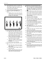
Safety points
1
Good arrangement
2
Correct work clothes
3
Following work standard
4
Making and checking signs
5
Prohibition of operation and handling by
unlicensed workers
6
Safety check before starting work
7
Wearing protective goggles
(for cleaning or grinding work)
8
Wearing shielding goggles and protectors
(for welding work)
9
Good physical condition and preparation
against work which you are not
10 Precautions
used to or you are used to too much
00-3
Safety notice
2.
Preparation for work
1) Before adding oil or making any repairs, park
the lift truck on hard and level ground, and
apply the parking brake and block the wheels
or tracks to prevent the lift truck from moving.
2) Before starting work, lower the work equipment (mast) to the ground. If this is not possible, insert the lock pin or use blocks to
prevent the work equipment from falling and
hang warning signs on them.
3) When disassembling or assembling, support
the lift truck with blocks, jacks, or stands
before starting work.
4) Remove all mud and oil from the steps or
other places used to get on and off the lift
truck. Always use the handrails and steps
when getting on or off the lift truck. N ever
jump on or off the lift truck.
00-4
FH40-1, FH45-1, FH50-1
Safety notice
3.
Precautions during work
1) Before disconnecting or removing components of the oil, water, or air circuits, first
release the pressure completely from the circuit. When removing the oil filler cap, a drain
plug, or an oil pressure pickup plug, loosen it
slowly to prevent the oil from spurting out.
2) The coolant and oil in the circuits are hot
when the engine is stopped, so be careful not
to get scalded. Wait for the oil and coolant to
cool before carrying out any work on the oil or
water circuits.
3) Before starting work, stop the engine. When
working on or around a rotating part, in particular, stop the engine. When checking the
machine without stopping the engine (measuring oil pressure, revolving speed, temperature, etc.), take extreme care not to get
rolled or caught in rotating parts or moving
parts.
4) Before starting work, remove the leads from
the battery. Always remove the lead from the
negative (-) terminal first.
5) When raising a heavy component (heavier
than 25 kg), use a hoist or crane. Before
starting work, check that the slings (wire
ropes, chains, and hooks) are free from damage. Always use slings which have ample
capacity and install them to proper places.
Operate the hoist or crane slowly to prevent
the component from hitting any other part. Do
not work with any part still raised by the hoist
or crane.
6) When removing a cover which is under internal pressure or under pressure from a spring,
always leave 2 bolts in diagonal positions.
Loosen those bolts gradually and alternately
to release the pressure, and then remove the
cover.
7) When removing components, be careful not
to break or damage the electrical wiring.
Damaged wiring may cause electrical fires.
8) When removing piping, stop the fuel or oil
from spilling out. If any fuel or oil drips onto
the floor, wipe it up immediately. Fuel or oil on
the floor can cause you to slip and can even
start fires.
9) As a general rule, do not use gasoline to
wash parts. Do not use it to clean electrical
parts, in particular.
10) Be sure to assemble all parts again in their
original places. Replace any damaged parts
and parts which must not be reused with new
parts. When installing hoses and wires, be
sure that they will not be damaged by contact
FH40-1, FH45-1, FH50-1
11)
12)
13)
14)
15)
with other parts when the lift truck is operated.
When installing high pressure hoses, make
sure that they are not twisted. Damaged
tubes are dangerous, so be extremely careful
when installing tubes for high pressure circuits. In addition, check that connecting parts
are correctly installed.
When assembling or installing parts, always
tighten them to the specified torques. When
installing protective parts such as guards, or
parts which vibrate violently or rotate at high
speed, be particularly careful to check that
they are installed correctly.
When aligning 2 holes, never insert your fingers or hand. Be careful not to get your fingers caught in a hole.
When measuring hydraulic pressure, check
that the measuring tools are correctly assembled.
If the engine is operated for a long time in a
place which is not ventilated well, you may
suffer from gas poisoning. Accordingly, open
the windows and doors to ventilate well.
00-5
Safety notice
4.
Safety items on maintenance (for safe work)
k
k
1)
1)
2)
k
1)
2)
3)
4)
5)
6)
7)
8)
k
1)
2)
3)
4)
5)
6)
7)
8)
9)
00-6
Inspection and maintenance shall be carried out by persons having maintenance
skill and experience.
Inspection and repair work of the lift trucks
shall be carried out by persons having sufficient knowledge and experience in maintenance and repair work.
When inspecting or servicing a new model or
a new component, fully understand its structure, performance and mechanism.
Precautions for inspection and maintenance work (preparation)
Perform inspection and maintenance on a
flat, dry, and dustless place.
When working in a warehouse, ventilate well.
Keep the inside of the maintenance shop
arranged well and work safely.
Prepare a fire extinguisher against a fire and
learn how to use it.
Before starting inspection work, lower the fork
to the ground.
Before starting inspection work, turn the starting switch OFF and pull out the key.
Turn the starting switch OFF and keep the
key pulled out unless necessary.
Pull the parking brake lever and put chocks in
front and rear of the front and rear tires.
2)
Periodic inspection of safety-critical parts
Replace the safety-critical parts periodically,
even if they are normal.
They are deteriorated as the time passes on
and can cause a fire and a trouble in the work
equipment system.
Replace safety-critical parts even before their
periodic replacement periods, if they are
abnormal.
k
Use of right tools and equipment
Use right tools for inspection and maintenance
work. Use of a broken tool or use a tool for a purpose other than its true purpose is very dangerous.
Precautions for inspection and maintenance work (safety)
If oil or grease is sticking, wipe it off. If oil
leaks, wipe it off immediately. Dirtiness hides
faults such as a crack. Keep clean.
No fire. Cloths impregnated with fuel or oil
can catch fire.
Wear adequate working clothes.
Use safety goods and protective items (helmet, safety shoes, goggles and gloves) suitable for work.
When working on the lift truck, take care not
to fall.
Do not put your foot under the fork.
When opening and closing the floor plate or
engine hood, take care not to have your hand
caught.
When inspecting with the fork raised, pat a
stand under the inner mast so that the fork
and mast will not fall.
When working with other personnel, appoint
a leader and follow his/her instructions.
FH40-1, FH45-1, FH50-1
Safety notice
k
1)
2)
3)
4)
Be careful of boiling coolant
The engine coolant is high in temperature
and pressure just after the lift truck is used.
Do not remove the radiator cap under this
condition. Hot coolant will spout and can
scald you.
When removing the radiator cap, loosen it
slowly to release the internal pressure.
When checking the coolant level, stop the
engine and wait for it and radiator to cool. If a
reservoir tank is installed, check it.
If a reservoir tank is installed, add coolant in
it.
k
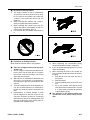
Prohibition of welding fuel tank
Never weld the fuel tank since it may explode.
5)
k
6)
1)
2)
3)
4)
Take care of high-pressure and high-temperature oil
The oil is high in temperature just after the lift
truck is used. Do not drain the oil or replace
the oil filter under this condition. Hot oil will
spout and can scald you.
Wait until the oil temperature decreases and
then carry out inspection or maintenance
according to the procedure described in this
manual.
There is residual pressure in the hydraulic circuit. Do not start inspection or maintenance
before the residual pressure decreases to
zero.
High-pressure oil leaking through a small
hole is dangerous to the skin or eye. Do not
check the hydraulic system for oil leakage
with naked eye but put on safety glasses and
thick gloves and put a piece of thick paper or
plywood to the inspection point.
FH40-1, FH45-1, FH50-1
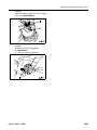
7)
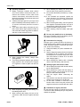
k
When inspecting the accumulator piping,
release the pressure inside it in advance.
If you are injured with high-pressure oil, see a
doctor immediately.
When removing the mast or lift cylinder, be
sure to release the pressure from the hydraulic piping.
q
Stop the lift truck and lower the fork to
the ground.
q
Stop the engine.
q
Turn the starting switch to the ACC position.
q
Sit on the operator seat and tilt the lift
lever and tilt lever forward and in reverse
4 - 5 times each to release the pressure
in the hydraulic piping.
The pressure is not released unless you
operate the levers while sitting on the
seat.
00-7
Safety notice
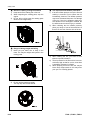
k
1)
2)
3)
Beware of rotating cooling fan and belt
Keep hand off the rotating fan or fan belt.
When inspecting the rotating parts, stop the
engine.
Do not bring a thing near the rotating parts
which can be caught easily.
k
1)
2)
k
1)
Danger of being caught and falling
Never put your hand, foot or body in the
mast. You may be caught and injured in the
moving parts.
3)
4)
5)
2)
00-8
Tire inspection and inflation procedures
If the tire inflation pressure is low, the lift truck
stability is lowered. Do not inflate the tire
immediately, however. The inflation pressure
may have decreased because of a damage
of the rim. If the tire is inflated to high pressure while the rim is damaged or cracked, the
tire will burst and cause an injury or a death.
When checking the tire inflation pressure,
place your body in front of the tread face of
the tire. Do not work from the side of the tire.
When inflating the tire, you have to have
taken the special education.
The air pressure for the lift truck tire is as several times high as that for car tire, thus there
is possibility of danger in inflating.
When pumping air into the tire, dirt may be
blown with compressed air and may enter
your eye. Put of safety glasses.
Do not use the mast as a ladder.
You may slip off the mast and fall.
FH40-1, FH45-1, FH50-1
Safety notice
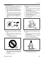
k
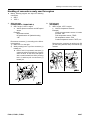
Handling of tires
Have the tire disassembled and assembled by a
specialist. Since the tire inflation pressure is very
high, the tires must be handled carefully.
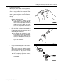
1) When removing the tire, release all air from it.
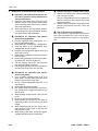
When removing the tire, loosen hub nut (1).
2) Never touch rim nut (2). Doing so is dangerous.
3) After replacing the tire, travel the lift truck on
trial and then check the mounting nuts for
looseness. If the tightening torque has
decreased, tighten to the specified torque.
4) Tightening torque: See “Standard value
table”.
k
1)
2)
Jack-up work (for checking or replacing
tire)
Do not go under the fork during jack-up work.
Check the following items before starting
jack-up work.
q
No person is on the lift truck.
q
No load is on the lift truck.
k
1)
2)
3)
4)
5)
6)
k
1)
2)
3)
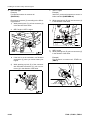
3)
4)
Stop jacking up when the tires are floated
above the ground a little and put blocks under
both sides of the frame to prevent the lift truck
from falling.
Lock the tires with chocks.
FH40-1, FH45-1, FH50-1
4)
Slinging lift truck (for checking or replacing tire)
Never sling the lift truck by the overhead
guard. When slinging the lift truck frequently,
use special slings.
The lift truck shall be slung by a person who
has finished the sling skill course.
Install wires to the specified slinging points.
When slinging the lift truck, use wires having
sufficient strength and no damage.
Lock the tires with chocks.
Put blocks under both sides of the slung lift
truck to prevent fall.
Slinging lift truck (for loading on trailer
etc.)
Never sling the lift truck by the overhead
guard. When slinging the lift truck frequently,
use special slings.
The lift truck shall be slung by a person who
has finished the sling skill course.
Install wires to the specified slinging points.
When slinging the lift truck, use wires having
sufficient strength and no damage.
00-9
Safety notice
k
1)
2)
3)
Handling of batteries
Battery electrolyte contains dilute sulfuric
acid, which attacks clothes and skins. If it
sticks to the clothes or skins, take off the
clothes immediately and wash the skins
which the electrolyte stuck with tap water and
then consult a doctor.
If battery electrolyte gets into your eyes, flush
them immediately with fresh tap water for 10 15 minutes continually and then consult a
doctor.
If you have drunk battery electrolyte by accident, either drink a large quantity of water or
milk mixed with beaten egg white or salad oil,
and then consult a doctor at once.
8)
9)
10)
11)
12)
13)
When installing the battery, be sure to connect the cable to the positive terminal first.
Do not short the battery terminals by a metallic thing.
If the terminals are loosened, sparks are
made because of a defective contact and
they can cause explosion. Tighten the terminals securely.
When removing the battery, check its positive
and negative terminals and take care not to
reconnect the cables with reverse polarities.
Tighten the battery caps securely.
When cleaning, keep the battery caps tightened.
k
Do not put a metallic piece on the battery.
Do not put a metallic piece on the battery, since it
can cause a fire from a short circuit.
k
4)
5)
When handling the battery, always wear
safety glasses.
The battery generates hydrogen gas, which is
highly explosive. Do not bring fire of a lighter
or a cigarette or make a spark near the battery.
Precautions for charging
Nitrogen gas is produced while the battery is
being charge and the battery heats itself because
of the chemical reaction. To prevent gas explosion, observe the following.
1) Charge the battery in a place ventilated well.
2) No fire.
3) Start to charge the battery when its electrolyte
temperature is 35°C or below. (If the electrolyte temperature increases above 50°C, wait
until it decreases to below 35°C and then
start charging again.)
4) When charging the battery with a charging
device, keep the battery caps removed.
k
1)
2)
3)
4)
5)
Starting engine with booster cables
When starting the engine with booster cables,
put on safety glasses.
When starting the engine with the battery of
another vehicle, do not bring the lift truck
body in contact with that vehicle.
Stop the engine before connecting the
cables.
Take extreme care that the cables will not be
caught in the cooling fan or the fan belt.
Do not make a mistake in connection of the
booster cable. Never bring the positive and
negative terminals in contact with each other.
k
6)
7)
00-10
When inspecting or handling the battery, turn
the starting switch OFF.
When removing the battery, be sure to disconnect the cable from the negative terminal
first.
Prohibition of engine push-start
Do not start the engine by pushing the lift truck.
The lift truck starts suddenly and you may make a
mistake in operation.
FH40-1, FH45-1, FH50-1
Safety notice
k
1)
2)
Handling of antifreeze
Antifreeze contains flammable material.
When handling it, do not bring fire near it.
Since antifreeze is toxic, do not drink it. If you
have swallowed by mistake, drink much
water and vomit and then consult a doctor
immediately.
k
Wastes
When disposing of oil, fuel, coolant, solvent, filter,
battery, Freon (air conditioner refrigerant), etc.,
observe the applicable regulations and rules.
5.
k
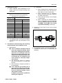
7)
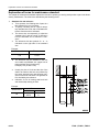
Slinging with 1 rope may cause turning of the load during hoisting,
untwisting of the rope, or slipping of
the rope from its original winding
position on the load, which can result
in a dangerous accident.
Limit the hanging angle to 60°, as a rule.
Do not sling a heavy load with ropes forming
a wide hanging angle from the hook.
When hoisting a load with 2 or more ropes,
the force subjected to each rope will increase
with the hanging angle. The table below
shows the variation of allowable load in kN
{kg} when hoisting is made with 2 ropes, each
of which is allowed to sling up to 9.8 kN
{1,000 kg} vertically, at various hanging
angles. When the 2 ropes sling a load vertically, up to 19.6 kN {2,000 kg} of total weight
can be suspended. This weight is reduced to
9.8 kN {1,000 kg} when the 2 ropes make a
hanging angle of 120°. If the 2 ropes sling a
19.6 kN {2,000 kg} load at a lifting angle of
150°, each of them is subjected to a force as
large as 39.2 kN {4,000 kg}.
Precautions for sling work and making signs
1) Only one appointed worker must make signs
and co-workers must communicate with each
other frequently. The appointed sign maker
must make specified signs clearly at a place
where he is seen well from the operator's
seat and where he can see the working condition easily. The sign maker must always
stand in front of the load and guide the operator safely.
q
Do not stand under the load.
q
Do not step on the load.
2) Check the slings before starting sling work.
3) Keep putting on gloves during sling work.
(Put on leather gloves, if available.)
4) Measure the weight of the load by the eye
and check its center of gravity.
5) Use proper sling according to the weight of
the load and method of slinging. If too thick
wire ropes are used to sling a light load, the
load may slip and fall.
6) Do not sling a load with 1 wire rope alone. If it
is slung so, it may rotate and may slip out of
the rope. Install 2 or more wire ropes symmetrically.
FH40-1, FH45-1, FH50-1
00-11
Safety notice
8)
When installing wire ropes to an angular load,
apply pads to protect the wire ropes. If the
load is slippery, apply proper material to prevent the wire rope from slipping.
9) Use the specified eyebolts and fix wire ropes,
chains, etc. to them with shackles, etc.
10) Apply wire ropes to the middle portion of the
hook.
q
Slinging near the tip of the hook may
cause the rope to slip off the hook during
hoisting. The hook has the maximum
strength at the middle portion.
11) Do not use twisted or kinked wire ropes.
12) When lifting up a load, observe the following.
q
Wind in the crane slowly until wire ropes
are stretched. When settling the wire
ropes with the hand, do not grasp them
but press them from above. If you grasp
them, your fingers may be caught.
q
After the wire ropes are stretched, stop
the crane and check the condition of the
slung load, wire ropes, and pads.
q
If the load is unstable or the wire rope or
chains are twisted, lower the load and lift
it up again.
q
Do not lift up the load slantingly.
13) When lifting down a load, observe the following.
q
When lifting down a load, stop it temporarily at 30 cm above the floor, and then
lower it slowly.
q
Check that the load is stable, and then
remove the sling.
q
Remove kinks and dirt from the wire
ropes and chains used for the sling work,
and put them in the specified place.
00-12
6.
Precautions for using overhead hoist crane
When raising a heavy part (heavier than 25
kg), use a hoist, etc. In Disassembly and
assembly, the weight of a part heavier
than 25 kg is indicated after the mark of
4.
1) Before starting work, inspect the wire ropes,
brake, clutch, controller, rails, over wind stop
device, electric shock prevention earth leakage breaker, crane collision prevention
device, and power application warning lamp,
and check safety.
2) Observe the signs for sling work.
3) Operate the hoist at a safe place.
4) Check the direction indicator plates (east,
west, south, and north) and the directions of
the control buttons without fail.
5) Do not sling a load slantingly. Do not move
the crane while the slung load is swinging.
6) Do not raise or lower a load while the crane is
moving longitudinally or laterally.
7) Do not drag a sling.
8) When lifting up a load, stop it just after it
leaves the ground and check safety, and then
lift it up.
9) Consider the travel route in advance and lift
up a load to a safe height.
10) Place the control switch on a position where it
will not be an obstacle to work and passage.
11) After operating the hoist, do not swing the
control switch.
12) Remember the position of the main switch so
that you can turn off the power immediately in
an emergency.
13) If the hoist stops because of a power failure,
turn the power switch OFF. When turning on
a switch which was turned OFF by the electric shock prevention earth leakage breaker,
check that the devices related to that switch
are not in operation state.
14) If you find an obstacle around the hoist, stop
the operation.
15) After finishing the work, stop the hoist at the
specified position and raise the hook to at
least 2 m above the floor. Do not leave the
sling installed to the hook.
k
FH40-1, FH45-1, FH50-1
Safety notice
7.
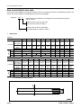
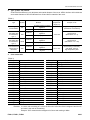
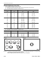
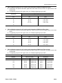
Selecting wire ropes
1) Select adequate ropes depending on the
weight of parts to be hoisted, referring to the
table below.
2)
1]
2]
Wire ropes
(Standard “Z” twist ropes without galvanizing)
(JIS G3525, No. 6, Type 6X37-A)
Nominal
diameter of rope
a
8.
3]
Allowable load
mm
kN
ton
10
8.8
0.9
12
12.7
1.3
14
17.3
1.7
16
22.6
2.3
18
28.6
2.9
20
35.3
3.6
25
55.3
5.6
30
79.6
8.1
40
141.6
14.4
50
221.6
22.6
60
318.3
32.4
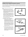
Connection
4]
When installing the air conditioner circuit
hoses and tubes, take care that dirt,
dust, water, etc. will not enter them.
When connecting the air conditioner
hoses and tubes, check that O-rings (1)
are fitted to their joints.
Check that each O-ring is not damaged
or deteriorated.
When connecting the refrigerant piping,
apply compressor oil for refrigerant
(R134a) (DENSO: ND-OIL8, VALEO
THERMAL SYSTEMS: ZXL100PG
(equivalent to PAG46)) to its O-rings.
a
Example of O-ring (Fitted to every joint of hoses
and tubes))
a
For tightening torque, see the precautions for
installation in each section of “Disassembly and
assembly”
The allowable load is one-sixth of the breaking strength of the rope used (Safety coefficient: 6).
Precautions for disconnecting and connecting
hoses and tubes in air conditioner circuit
1)
Disconnection
k
a
a
k
The air conditioner mounted on this lift
truck uses refrigerant (R134a), which
must not be discharged into the atmosphere as it is, although it has less
ozone layer breaking factors for preservation of the environment. When disconnecting the air conditioner gas
circuit, be sure to collect the refrigerant to reuse it.
Ask professional traders for collecting
and filling operation of refrigerant
(R134a).
Never release the refrigerant (R134a) to
the atmosphere.
If the refrigerant gas (R134a) gets in
your eyes, you may lose your sight.
When collecting or filling the it, be sure
to put on protective goggles, gloves
and protective clothes.
In addition, you must be qualified for
handling the refrigerant.
FH40-1, FH45-1, FH50-1
00-13
How to read the shop manual
How to read the shop manual
q
q
q
1.
Some attachments and optional parts in this shop manual may not be delivered to certain areas. If one
of them is required, consult KOMATSU FORKLIFT distributors.
Materials and specifications are subject to change without notice.
Shop manuals are divided into the “Chassis volume” and “Engine volume”. For the engine unit, refer to
engine shop manual SM204.
Composition of shop manual
This shop manual contains the necessary technical information for services performed in a workshop. For
ease of understanding, the manual is divided into the following sections.
00. Foreword
This section explains the shop manuals list, safety, and basic information.
01. Specification
This section explains the specifications of the lift truck.
10. Structure, function and maintenance standard
This section explains the structure, function, and maintenance standard values of each component. The
structure and function sub-section explains the structure and function of each component. It serves not
only to give an understanding of the structure, but also serves as reference material for troubleshooting.
The maintenance standard sub-section explains the criteria and remedies for disassembly and service.
20. Standard value table
This section explains the standard values for new machine and judgement criteria for testing, adjusting,
and troubleshooting. This standard value table is used to check the standard values in testing and adjusting and to judge parts in troubleshooting.
30. Testing and adjusting
This section explains measuring instruments and measuring methods for testing and adjusting, and
method of adjusting each part. The standard values and judgement criteria for testing and adjusting are
explained in Testing and adjusting.
40. Troubleshooting
This section explains how to find out failed parts and how to repair them. The troubleshooting is divided by
failure modes. For troubleshooting “S mode” related to the engine, see Engine.
50. Disassembly and assembly
This section explains the special tools and procedures for removing, installing, disassembling, and
assembling each component, as well as precautions for them. In addition, tightening torque and quantity
and weight of coating material, oil, grease, and coolant necessary for the work are also explained.
80. Yearly inspection criteria
This section explains the items, contents and criteria of the specific self-imposed inspection.
90. Diagrams and drawings (Chassis)
This section gives hydraulic circuit diagrams and electrical circuit diagrams.
00-14
FH40-1, FH45-1, FH50-1
How to read the shop manual
2.
3.
Symbols
Important safety and quality portions are marked with the following symbols so that the shop manual will be
used practically.
Symbol
Item
Remarks
1
Security
k
Safety
Special safety precautions are necessary when performing work.
a
Caution
Special technical precautions or other precautions for preserving
standards are necessary when performing work.
4
Weight
Weight of parts of component or parts. Caution necessary when
selecting hoisting wire, or when working posture is important, etc.
3
Tightening
torque
2
Coat
5
Oil, coolant
6
Drain
Special precautions are necessary for lift truck security during
assembly work.
Places that require special attention for tightening torque during
assembly.
Places to be coated with adhesives, etc. during assembly.
Places where oil, etc. must be added, and capacity.
Places where oil, etc. must be drained, and quantity to be drained.
Unit
In this shop manual, the units are indicated with International System of units (SI). For reference, conventionally used Gravitational System of units is indicated in parentheses { }.
FH40-1, FH45-1, FH50-1
00-15
Explanation of terms for maintenance standard
Explanation of terms for maintenance standard
The chapter of maintenance standard explains the criteria for replacing or reusing each product or part in the disassembly maintenance. The criteria are described by the following terms.
1.
Standard size and tolerance
q
To be accurate, the finishing size of parts is a
little different from one to another.
q
To specify a finishing size of a part, a temporary standard size is set and an allowable difference from that size is indicated.
q
The above size set temporarily is called the
“standard size” and the range of difference
from the standard size is called the “tolerance”.
q
The tolerance with the symbols of + or - is
indicated on the right side of the standard
size.
Example:
Standard size
Tolerance
-0.022
-0.126
120
a
The tolerance may be indicated in the text
and a table as [standard size (upper limit of
tolerance/lower limit of tolerance)].
Example) 120 (-0.022/-0.126)
q
Usually, the size of a hole and the size of the
shaft to be fitted to that hole are indicated by
the same standard size and different tolerances of the hole and shaft. The tightness of
fit is decided by the tolerance.
Indication of size of rotating shaft and hole
and relationship drawing of them
q
Example:
Standard size
60
00-16
Tolerance
Shaft
-0.030
-0.076
Hole
+0.046
+0
FH40-1, FH45-1, FH50-1
Explanation of terms for maintenance standard
2.
3.
Standard clearance and standard value
q
The clearance made when new parts are
assembled is called the “standard clearance”,
which is indicated by the range from the minimum clearance to the maximum clearance.
q
When some parts are repaired, the clearance
is generally adjusted to the standard clearance.
q
A value of performance and function of new
products or equivalent is called the “standard
value”, which is indicated by a range or a target value.
q
When some parts are repaired, the value of
performance/function is set to the standard
value.
Standard interference
When the diameter of a hole of a part shown
in the given standard size and tolerance table
is smaller than that of the mating shaft, the
difference between those diameters is called
the “interference”.
q
The range (A - B) from the difference (A)
between the minimum size of the shaft and
the maximum size of the hole to the difference (B) between the maximum size of the
shaft and the minimum size of the hole is the
“standard interference”.
q
After repairing or replacing some parts, measure the size of their hole and shaft and
check that the interference is in the standard
range.
q
4.
5.
Clearance limit
Parts can be used until the clearance
between them is increased to a certain limit.
The limit at which those parts cannot be used
is called the “clearance limit”.
q
If the clearance between the parts exceeds
the clearance limit, they must be replaced or
repaired.
q
6.
Interference limit
The
allowable
maximum
interference
between the hole of a part and the shaft of
another part to be assembled is called the
“interference limit”.
q
The interference limit shows the repair limit of
the part of smaller tolerance.
q
If the interference between the parts exceeds
the interference limit, they must be replaced
or repaired.
q
Repair limit and allowable value or allowable
dimension
q
The size of a part changes because of wear
and deformation while it is used. The limit of
changed size is called the “repair limit”.
q
If a part is worn to the repair limit must be
replaced or repaired.
q
The performance and function of a product
lowers while it is used. A value below which
the product can be used without causing a
problem is called the “allowable value” or
“allowable dimension”.
q
If a product is worn to the allowable value, it
must be checked or repaired. Since the permissible value is estimated from various tests
or experiences in most cases, however, it
must be judged after considering the operating condition and customer's requirement.
FH40-1, FH45-1, FH50-1
00-17
Handling of electric equipment and hydraulic component
Handling of electric equipment and hydraulic component
To maintain the performance of the machine over a long period, and to prevent failures or other troubles before
they occur, correct “operation”, “maintenance and inspection”, “troubleshooting”, and “repairs” must be carried out.
This section deals particularly with correct repair procedures for mechatronics and is aimed at improving the quality
of repairs. For this purpose, it gives sections on “Handling electric equipment” and “Handling hydraulic equipment”
(particularly gear oil and hydraulic oil).
Points to remember when handling electric equipment
1. Handling wiring harnesses and connectors
Wiring harnesses consist of wiring connecting one
component to another component, connectors
used for connecting and disconnecting one wire
from another wire, and protectors or tubes used
for protecting the wiring.
Compared with other electrical components fitted
in boxes or cases, wiring harnesses are more
likely to be affected by the direct effects of rain,
water, heat, or vibration. Furthermore, during
inspection and repair operations, they are frequently removed and installed again, so they are
likely to suffer deformation or damage. For this
reason, it is necessary to be extremely careful
when handling wiring harnesses.
2.
Main failures occurring in wiring harness
1) Defective contact of connectors (defective
contact between male and female)
Problems with defective contact are likely to
occur because the male connector is not
properly inserted into the female connector,
or because one or both of the connectors is
deformed or the position is not correctly
aligned, or because there is corrosion or oxidation of the contact surfaces. The corroded
or oxidized contact surfaces may become
shiny again (and contact may become normal) by connecting and disconnecting the
connector about 10 times.
2)
00-18
Defective crimping or soldering of connectors
The pins of the male and female connectors
are in contact at the crimped terminal or soldered portion, but if there is excessive force
brought to bear on the wiring, the plating at
the joint will peel and cause improper connection or breakage.
FH40-1, FH45-1, FH50-1
Handling of electric equipment and hydraulic component
3)
Disconnections in wiring
If the wiring is held and the connectors are
pulled apart, or components are lifted with a
crane with the wiring still connected, or a
heavy object hits the wiring, the crimping of
the connector may separate, or the soldering
may be damaged, or the wiring may be broken.
4)
High-pressure water entering connector
The connector is designed to make it difficult
for water to enter (drip-proof structure), but if
high-pressure water is sprayed directly on the
connector, water may enter the connector,
depending on the direction of the water jet.
Accordingly, take care not to splash water
over the connector.
The connector is designed to prevent water
from entering, but at the same time, if water
does enter, it is difficult for it to be drained.
Therefore, if water should get into the connector, the pins will be short-circuited by the
water, so if any water gets in, immediately dry
the connector or take other appropriate action
before passing electricity through it.
5)
Oil or dirt stuck to connector
If oil or grease are stuck to the connector and
an oil film is formed on the mating surface
between the male and female pins, the oil will
not let the electricity pass, so there will be
defective contact. If there is oil or grease
stuck to the connector, wipe it off with a dry
cloth or blow it dry with compressed air and
spray it with a contact restorer.
a When wiping the mating portion of the
connector, be careful not to use excessive force or deform the pins.
a If there is oil or water in the compressed
air, the contacts will become even dirtier,
so remove the oil and water from the
compressed air completely before cleaning with compressed air.
FH40-1, FH45-1, FH50-1
00-19
Handling of electric equipment and hydraulic component
3.
Removing, installing, and drying connectors
and wiring harnesses
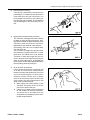
1) Disconnecting connectors
1] Hold the connectors when disconnecting.
When disconnecting the connectors,
hold the connectors. For connectors held
by a screw, loosen the screw fully, then
hold the male and female connectors in
each hand and pull apart. For connectors
which have a lock stopper, press down
the stopper with your thumb and pull the
connectors apart.
a Never pull with one hand.
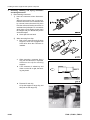
2]
When removing from clips
q
Both of the connector and clip have
stoppers, which are engaged with
each other when the connector is
installed.
q
a
a
00-20
When removing a connector from a
clip, pull the connector in a parallel
direction to the clip for removing
stoppers.
If the connector is twisted up and
down or to the left or right, the housing may break.
Removal of resin clip
Lift up the stopper of range clip, and
then pull out the range clip.
FH40-1, FH45-1, FH50-1
Handling of electric equipment and hydraulic component
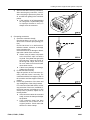
3]
2)
Action to take after removing connectors
After removing any connector, cover it
with a vinyl bag to prevent any dust, dirt,
oil, or water from getting in the connector
portion.
a If the machine is left disassembled
for a long time, it is particularly easy
for improper contact to occur, so
always cover the connector.
Connecting connectors
1] Check the connector visually.
Check that there is no oil, dirt, or water
stuck to the connector pins (mating portion).
Check that there is no deformation,
defective contact, corrosion, or damage
to the connector pins.
Check that there is no damage or breakage to the outside of the connector.
a If there is any oil, water, or dirt stuck
to the connector, wipe it off with a
dry cloth. If any water has got inside
the connector, warm the inside of
the wiring with a dryer, but be careful not to make it too hot as this will
cause short circuits.
a If there is any damage or breakage,
replace the connector.
2] Fix the connector securely.
Align the position of the connector correctly, and then insert it securely. For
connectors with the lock stopper, push in
the connector until the stopper clicks into
position.
3] Correct any protrusion of the boot and
any misalignment of the wiring harness.
For connectors fitted with boots, correct
any protrusion of the boot. In addition, if
the wiring harness is misaligned, or the
clamp is out of position, adjust it to its
correct position.
a If the connector cannot be corrected
easily, remove the clamp and adjust
the position.
q
If the connector clamp has been
removed, be sure to return it to its
original position. Check also that
there are no loose clamps.
FH40-1, FH45-1, FH50-1
00-21
Handling of electric equipment and hydraulic component
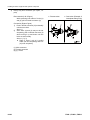
3)
Heavy duty wire connector (DT 8-pole, 12pole)
Disconnection (Left of figure)
While pressing both sides of locks (a)
and (b), pull out female connector (2).
q
Disconnection
q
Connection (Example of
incomplete setting of (a))
Connection (Right of figure)
1] Push in female connector (2) horizontally
until the lock clicks.
Arrow: 1)
2] Since locks (a) and (b) may not be set
completely, push in female connector (2)
while moving it up and down until the
locks are set normally.
Arrow: 1), 2), 3)
a Right of figure: Lock (a) is pulled
down (not set completely) and lock
(b) is set completely.
(1): Male connector
(2): Female connector
(a), (b): Locks
00-22
FH40-1, FH45-1, FH50-1
Handling of electric equipment and hydraulic component
4)
Drying wiring harness
If there is any oil or dirt on the wiring harness,
wipe it off with a dry cloth. Avoid washing it in
water or using steam. If the connector must
be washed in water, do not use high-pressure
water or steam directly on the wiring harness.
If water gets directly on the connector, do as
follows.
1] Disconnect the connector and wipe off
the water with a dry cloth.
a If the connector is blown dry with
compressed air, there is the risk that
oil in the air may cause defective
contact, so remove all oil and water
from the compressed air before
blowing with air.
2] Dry the inside of the connector with a
dryer.
If water gets inside the connector, use a
dryer to dry the connector.
a Hot air from the dryer can be used,
but regulate the time that the hot air
is used in order not to make the connector or related parts too hot, as
this will cause deformation or damage to the connector.
3]
Carry out a continuity test on the connector.
After drying, leave the wiring harness
disconnected and carry out a continuity
test to check for any short circuits
between pins caused by water.
a After completely drying the connector, blow it with contact restorer and
reassemble.
FH40-1, FH45-1, FH50-1
00-23
Handling of electric equipment and hydraulic component
4.
Handling controller
1) The controller contains a microcomputer and
electronic control circuits. microcomputer and
electronic control circuits. These control all of
the electronic circuits on the machine, so be
extremely careful when handling the controller.
2) Do not place objects on top of the controller.
3) Cover the control connectors with tape or a
vinyl bag. Never touch the connector contacts
with your hand.
4) During rainy weather, do not leave the controller in a place where it is exposed to rain.
5) Do not place the controller on oil, water, or
soil, or in any hot place, even for a short time.
(Place it on a suitable dry stand).
6) Precautions when carrying out arc welding
When carrying out arc welding on the body,
disconnect all wiring harness connectors connected to the controller. Fit an arc welding
ground close to the welding point.
5.
Points to remember when troubleshooting electric circuits
1) Always turn the power OFF before disconnecting or connecting connectors.
2) Before carrying out troubleshooting, check
that all the related connectors are properly
inserted.
a Disconnect and connect the related connectors several times to check.
3) Always connect any disconnected connectors
before going on to the next step.
a If the power is turned ON with the connectors still disconnected, unnecessary
abnormality displays will be generated.
4) When carrying out troubleshooting of circuits
(measuring the voltage, resistance, continuity, or current), move the related wiring and
connectors several times and check that
there is no change in the reading of the tester.
a If there is any change, there is probably
defective contact in that circuit.
00-24
FH40-1, FH45-1, FH50-1
Handling of electric equipment and hydraulic component
Points to remember when handling hydraulic equipment
With the increase in pressure and precision of hydraulic equipment, the most common cause of failure is dirt (foreign material) in the hydraulic circuit. When adding hydraulic oil, or when disassembling or assembling hydraulic
equipment, it is necessary to be particularly careful.
1.
Be careful of the operating environment.
Avoid adding hydraulic oil, replacing filters, or
repairing the machine in rain or high winds, or
places where there is a lot of dust.
2.
Disassembly and maintenance work in the field
If disassembly or maintenance work is carried out
on hydraulic equipment in the field, there is danger of dust entering the equipment. It is also difficult to check the performance after repairs, so it is
desirable to use unit exchange. Disassembly and
maintenance of hydraulic equipment should be
carried out in a specially prepared dust proof
workshop, and the performance should be
checked with special test equipment.
3.
Sealing openings
After any piping or equipment is removed, the
openings should be sealed with caps, tapes, or
vinyl bags to prevent any dirt or dust from entering. If the opening is left open or is blocked with a
rag, there is danger of dirt entering or of the surrounding area being made dirty by leaking oil so
never do this. Do not simply drain oil out onto the
ground, but collect it and ask the customer to dispose of it, or take it back with you for disposal.
4.
Do not let any dirt or dust get in during refilling
operations
Be careful not to let any dirt or dust get in when
refilling with hydraulic oil. Always keep the oil filler
and the area around it clean, and also use clean
pumps and oil containers. If an oil cleaning device
is used, it is possible to filter out the dirt that has
collected during storage, so this is an even more
effective method.
FH40-1, FH45-1, FH50-1
00-25
Handling of electric equipment and hydraulic component
5.
Change hydraulic oil when the temperature is
high
When hydraulic oil or other oil is warm, it flows
easily. In addition, the sludge can also be drained
out easily from the circuit together with the oil, so
it is best to change the oil when it is still warm.
When changing the oil, as much as possible of the
old hydraulic oil must be drained out. (Drain the oil
from the hydraulic tank; also drain the oil from the
filter and from the drain plug in the circuit.) If any
old oil is left, the contaminants and sludge in it will
mix with the new oil and will shorten the life of the
hydraulic oil.
6.
Flushing operations
After disassembling and assembling the equipment, or changing the oil, use flushing oil to
remove the contaminants, sludge, and old oil from
the hydraulic circuit. Normally, flushing is carried
out twice: primary flushing is carried out with
flushing oil, and secondary flushing is carried out
with the specified hydraulic oil.
7.
Cleaning operations
After repairing the hydraulic equipment (pump,
control valve, etc.) or when running the machine,
carry out oil cleaning to remove the sludge or contaminants in the hydraulic oil circuit. The oil cleaning equipment is used to remove the ultra fine
(about 3 m ) particles that the filter built in the
hydraulic equipment cannot remove, so it is an
extremely effective device.
00-26
FH40-1, FH45-1, FH50-1
Handling of connectors newly used for engines
Handling of connectors newly used for engines
a
Mainly, following engines are object for following
connectors.
q
95E-5
q
107E-1
1.
Slide lock type
(FRAMATOME-3, FRAMATOME-2)
q
95E-5 engine, 107E-1 engine
q
Various pressure sensors and NE speed
sensor
Example)
Oil pressure switch
Ne speed sensor of flywheel housing
: NE
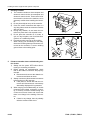
Disconnect connector (1) according to the following procedure.
1) Slide lock L1 to the right.
2) While pressing lock L2, pull out connector (1)
toward you.
a Even if lock L2 is pressed, connector (1)
cannot be pulled out toward you, if part A
does not float. In this case, float part A
with a small screwdriver while pressing
lock L2, and then pull out connector (1)
toward you.
FH40-1, FH45-1, FH50-1
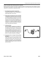
2.
Pull lock type
(PACKARD-2)
q
95E-5 engine, 107E-1 engine
q
Various temperature sensors
Example)
Intake air temperature sensor in intake
manifold: TIM
Fuel temperature sensor: TFUEL
Oil temperature sensor: TOIL
Coolant temperature sensor: TWTR, etc.
Disconnect the connector by pulling lock (B)
(on the wiring harness side) of connector (2)
outward.
00-27
Handling of connectors newly used for engines
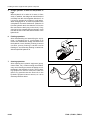
3.
Push lock type
Example)
Fuel pressure sensor in common rail
(BOSCH-03)
q
107E-1 engine
Example)
Intake air pressure/temperature sensor in
intake manifold (SUMITOMO-04)
Disconnect connector (3) according to the following procedure.
1) While pressing lock (C), pull out connector (3)
in the direction of the arrow.
3)
While pressing lock (D), pull out connector (4)
in the direction of the arrow.
q
95E-5 engine
While pressing lock (E), pull out connector (5)
in the direction of the arrow.
q
95E-5 engine, 107E-1 engine
4)
a
If the lock is on the underside, use flat-head
screwdriver [1] since you cannot insert your
fingers.
2)
While pressing up lock (C) of the connector
with flat-head screwdriver [1], pull out connector (3) in the direction of the arrow.
00-28
Example)
Fuel pressure in common rail: PFUEL etc.
(AMP-3)
FH40-1, FH45-1, FH50-1
Handling of connectors newly used for engines
Example)
Injection pressure control valve of fuel supply
pump: PCV (SUMITOMO-2)
Example)
Speed sensor of fuel supply pump:
G (SUMITOMO-3)
a Pull the connector straight up.
FH40-1, FH45-1, FH50-1
00-29
How to read electric wire code
How to read electric wire code
In the electric circuit diagram, the material, thickness, and color of each electric wire are indicated by symbols. The
electric wire code is helpful in understanding the electric circuit diagram.
Example:
0.85
L - - - Indicates blue, heat-resistant, low-voltage wire for automobile, having nominal No. of 0.85.
Indicates color of wire by color code.
Color codes are shown in Table 3.
Indicates size of wire by nominal No.
Size (Nominal No.) is shown in Table 2.
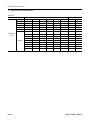
1.
Dimensions
(Table 2)
0.75f
CoVer D
Nominal No.
Number of
strands/Diameter of strand
Conductor
Sectional area
(mm2)
d (approx.)
AVS
Standard
AV
Standard
CAVS
Standard
AEX
Standard
(0.85)
1.25f
(1.25)
2f
2
3f
3
5
30/0.18 11/0.32 50/0.18 16/0.32 37/0.26 26/0.32 58/0.26 41/0.32 65/0.32
Cover D
Nominal No.
0.5f
(0.5)
Number of
strands/Diam- 20/0.18 7/0.32
eter of strand
Conductor
Sectional area
0.51
0.56
(mm2)
d (approx.)
1.0
AVS
Standard
2.0
AV
Standard
–
CAVS
Standard
–
1.6
AEX
Standard
2.0
0.76
0.88
1.27
1.2
2.2
–
–
1.29
1.5
2.5
–
1.8
–
2.2
2.1
2.7
1.96
2.09
3.08
3.30
5.23
1.9
2.9
–
–
3.0
1.9
2.9
–
–
3.1
2.3
3.5
–
–
–
2.4
3.6
–
–
3.8
3.0
–
4.6
–
4.6
8
15
20
30
40
50
60
85
100
50/0.45
84/0.45
41/0.80
70/0.80
85/0.80
108/0.80
127/0.80
169/0.80
217/0.80
7.95
13.36
20.61
35.19
42.73
54.29
63.84
84.96
109.1
3.7
–
5.5
–
5.3
4.8
–
7.0
–
7.0
6.0
–
8.2
–
8.2
8.0
–
10.8
–
10.8
8.6
–
11.4
–
11.4
9.8
–
13.0
–
13.0
10.4
–
13.6
–
13.6
12.0
–
16.0
–
16.0
13.6
–
17.6
–
17.6
“f” of nominal No. denotes “flexible”.
00-30
FH40-1, FH45-1, FH50-1
How to read electric wire code
2.
Type, symbol, and material
AV and AVS are different in only thickness and outside diameter of the cover. AEX is similar to AV in thickness
and outside diameter of AEX and different from AV and AVS in material of the cover.
(Table 1)
Type
Symbol
Low-voltage wire
for automobile
AV
Thin-cover
low-voltage wire
for automobile,
type 1
Thin-cover
low-voltage wire
for automobile,
type 2
Heat-resistant lowvoltage wire for
automobile
3.
Using
temperature
range (°C)
Material
Conductor
Insulator
Conductor
AVS
Annealed copper for electric
appliance
Soft polyvinyl chloride
Annealed copper for electric
appliance
Insulator
Soft polyvinyl chloride
Conductor
Annealed copper for electric
appliance
Insulator
Soft polyvinyl chloride
CAVS
Conductor
AEX
Insulator
Annealed copper for electric
appliance
Heat-resistant crosslinked polyethylene
Example of use
Wiring conducting large current
(Nominal No. 5 and above)
-30 to +60
General wiring
(Nominal No. 0.5 - 3)
General wiring
(Nominal No. 0.5 - 1.25)
-50 to +110
General wiring in extremely
cold district, wiring at
high-temperature place
Color codes table
(Table 3)
Color code
B
Br
BrB
BrR
BrW
BrY
Ch
Dg
G
GB
GL
Gr
GR
GW
GY
L
LB
Lg
LgB
LgR
Color of wire
Black
Brown
Brown & Black
Brown & Red
Brown & White
Brown & Yellow
Charcoal
Dark green
Green
Green & Black
Green & Blue
Gray
Green & Red
Green & White
Green & Yellow
Blue
Blue & Black
Light green
Light green & Black
Light green & Red
Color code
LgW
LgY
LR
LW
LY
O
P
R
RB
RG
RL
RW
RY
Sb
Y
YB
YG
YL
YR
YW
Color of wire
Light green & White
Light green & Yellow
Blue & Red
Blue & White
Blue & Yellow
Orange
Pink
Red
Red & Black
Red & Green
Red & Blue
Red & White
Red & Yellow
Sky Blue
Yellow
Yellow & Black
Yellow & Green
Yellow & Blue
Yellow & Red
Yellow & White
Remarks: In a color code consisting of 2 colors, the first color is the color of the background and the second color is the color of the marking.
Example: “GW” means that the background is Green and marking is White.
FH40-1, FH45-1, FH50-1
00-31
How to read electric wire code
4.
Types of circuits and color codes
(Table 4)
Type of wire
Charge
Ground
Start
Light
Instrument
Signal
Type of circuit
Others
00-32
R
B
R
RW
Y
G
L
Br
Lg
O
Gr
P
Sb
Dg
Ch
WG
–
–
RB
YR
GW
LW
BrW
LgR
–
–
–
–
–
–
AVS or AV
–
–
–
–
–
–
RY
RG
YB
YG
GR
GY
LR
LY
BrR
BrY
LgY
LgB
–
–
–
–
–
–
–
–
–
–
–
–
AEX
–
–
–
RL
YL
GB
LB
BrB
LgW
–
–
–
–
–
–
–
–
–
–
YW
GL
–
–
–
–
–
–
–
–
–
R
B
R
D
Y
G
L
–
–
–
–
–
–
–
–
–
–
–
–
Gr
Br
–
–
–
–
–
–
–
–
–
FH40-1, FH45-1, FH50-1
Precautions when carrying out operation
Precautions when carrying out operation
When carrying out removal, installation, disassembly or assembly of units, be sure to follow the general precautions given below.
1.
q
q
q
q
q
q
q
q
q
q
a
Precautions when carrying out removal work
If the coolant contains antifreeze, dispose of it correctly.
After disconnecting hoses or tubes, cover them or fit plugs to prevent dirt or dust from entering.
When draining oil, prepare a container of adequate size to catch the oil.
Confirm the match marks showing the installation position, and make match marks in the necessary places
before removal to prevent any mistake when assembling.
To prevent any excessive force from being applied to the wiring, always hold the connectors when disconnecting the connectors.
Fit wires and hoses with tags to show their installation position to prevent any mistake when installing.
Check the number and thickness of the shims, and keep in a safe place.
When raising components, be sure to use lifting equipment of ample strength.
When using forcing screws to remove any components, tighten the forcing screws uniformly in turn.
Before removing any unit, clean the surrounding area and fit a cover to prevent any dust or dirt from entering
after removal.
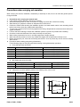
Precautions when handling piping during disassembly
Fit the following plugs into the piping after disconnecting it during disassembly operations.
1) Face seal type hoses and tubes
Nominal No.
02
03
04
05
06
2)
Nut (elbow end)
02789-00210
02789-00315
02789-00422
02789-00522
02789-00628
Split flange type hoses and tubes
Nominal No.
04
05
3)
Plug (nut end)
07376-70210
07376-70315
07376-70422
07376-70522
07376-70628
Flange (hose end)
07379-00400
07379-00500
Sleeve head (tube end)
07378-10400
07378-10500
Split flange
07371-30400
07371-30500
If the part is not under hydraulic pressure, the following corks can be used.
Nominal No.
Part Number
06
08
10
12
14
16
18
20
22
24
07049-00608
07049-00811
07049-01012
07049-01215
07049-01418
07049-01620
07049-01822
07049-02025
07049-02228
07049-02430
27
07049-02734
FH40-1, FH45-1, FH50-1
Dimensions (mm)
D
d
L
6
5
8
8
6.5
11
10
8.5
12
12
10
15
14
11.5
18
16
13.5
20
18
15
22
20
17
25
22
18.5
28
24
20
30
22.5
22.5
34
00-33
Precautions when carrying out operation
2.
q
q
q
q
q
q
q
q
q
q
q
q
q
a
a
3.
Precautions when carrying out installation
work
Tighten all bolts and nuts (sleeve nuts) to the specified (KES) torque.
Install the hoses without twisting or interference and fix them with intermediate clamps, if there are any.
Replace all gaskets, O-rings, cotter pins, and lock plates with new parts.
Bend the cotter pins and lock plates securely.
When coating with adhesive, clean the part and remove all oil and grease, then coat the threaded portion with
2 - 3 drops of adhesive.
When coating with gasket sealant, clean the surface and remove all oil and grease, check that there is no dirt
or damage, then coat uniformly with gasket sealant.
Clean all parts, and correct any damage, dents, burrs, or rust.
Coat rotating parts and sliding parts with engine oil.
When press fitting parts, coat the surface with anti-friction compound (LM-P).
After fitting snap rings, check that the snap ring is fitted securely in the ring groove.
When connecting wiring connectors, clean the connector to remove all oil, dirt, or water, then connect
securely.
When using eyebolts, check that there is no deformation or deterioration, screw them in fully, and align the
direction of the hook.
When tightening split flanges, tighten uniformly in turn to prevent excessive tightening on one side.
When operating the hydraulic cylinders for the first time after reassembling cylinders, pumps and other hydraulic equipment removed for repair, always bleed the air as follows:
1) Start the engine and run at low idle.
2) Operate the work equipment control lever to operate the hydraulic cylinder 4 - 5 times, stopping the cylinder 100 mm from the end of its stroke.
3) Next, operate the hydraulic cylinder 3 - 4 times to the end of its stroke.
When using the lift truck for the first time after repair or long storage, follow the same procedure.
Precautions when completing operation
1) Refilling with coolant, oil and grease
q
If the coolant has been drained, tighten the drain valve, and add coolant to the specified level. Run
the engine to circulate the coolant through the system. Then check the coolant level again.
q
If the hydraulic equipment has been removed and installed again, add engine oil to the specified
level. Run the engine to circulate the oil through the system. Then check the oil level again.
q
If the hydraulic equipment has been removed, always bleed the air from the system after reassembling the parts, referring to Testing and adjusting.
q
Add the specified amount of grease (molybdenum disulfide grease) to the work equipment parts.
2) Checking cylinder head and manifolds for looseness
Check the cylinder head and intake and exhaust manifold for looseness.
If any part is loosened, retighten it.
q
For the tightening torque, see “Disassembly and assembly”.
3) Checking engine piping for damage and looseness
Intake and exhaust system
Check the piping for damage, the mounting bolts and nuts for looseness, and the joints for air suction
and exhaust gas leakage.
If any part is loosened or damaged, retighten or repair it.
Cooling system
Check the piping for damage, the mounting bolts and nuts for looseness, and the joints for coolant
leakage.
If any part is loosened or damaged, retighten or repair it.
Fuel system
Check the piping for damage, the mounting bolts and nuts for looseness, and the joints for fuel leakage.
If any part is loosened or damaged, retighten or repair it.
00-34
FH40-1, FH45-1, FH50-1
Precautions when carrying out operation
4)
5)
Checking muffler and exhaust pipe for damage and looseness
1] Visually check the muffler, exhaust pipe and their mounting parts for a crack and damage.
If any part is damaged, replace it.
2] Check the mounting bolts and nuts of the muffler, exhaust pipe and their mounting parts for looseness.
If any part is loosened, retighten it.
Checking muffler function
Check the muffler for abnormal sound and sound different from that of a new muffler.
If any abnormal sound is heard, repair the muffler, referring to “Troubleshooting” and “Disassembly and
assembly”.
FH40-1, FH45-1, FH50-1
00-35
Standard tightening torque table
Standard tightening torque table
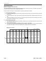
1.
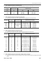
Table of tightening torques for bolts and nuts
a Unless there are special instructions, tighten metric nuts and bolts to the torque below.
a The following table corresponds to the bolts in Fig. A.
Bolt Thread diameter
mm
6
8
10
12
14
16
18
20
22
24
27
30
33
36
39
a
Tightening torque
Nm
11.8 - 14.7
27 - 34
59 - 74
98 - 123
157 - 196
245 - 309
343 - 427
490 - 608
662 - 829
824 - 1,030
1,180 - 1,470
1,520 - 1,910
1,960 - 2,450
2,450 - 3,040
2,890 - 3,630
kgfm
1.2 - 1.5
2.8 - 3.5
6.0 - 7.5
10.0 - 12.5
16 - 20
25 - 31.5
35 - 43.5
50 - 62
67.5 - 84.5
84 - 105
120 - 150
155 - 195
200 - 250
250 - 310
295 - 370
The following table corresponds to the bolts in Fig. B.
Bolt Thread diameter
mm
6
8
10
12
a Fig. A
Width across flats
mm
10
13
17
19
22
24
27
30
32
36
41
46
50
55
60
Width across flats
mm
10
12
14
27
Tightening torque
Nm
5.9 - 9.8
13.7 - 23.5
34.3 - 46.1
74.5 - 90.2
kgfm
0.6 - 1.0
1.4 - 2.4
3.5 - 4.7
7.6 - 9.2
a Fig. B
Remarks: The widths across flats against the thread diameters of flanged bolts (marks with “*”) in Fig. A are the
ones indicated in the table for bolts shown in Fig. B.
(Values of tightening torques shown in the table for Fig. A are applied.)
00-36
FH40-1, FH45-1, FH50-1
Standard tightening torque table
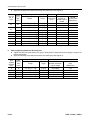
2.
Table of tightening torques for split flange bolts
a Unless there are special instructions, tighten split flange bolts to the torque below.
Thread diameter
of bolt
mm
10
12
16
3.
02
03, 04
05, 06
10, 12
14
mm
14
17
22
Nm
59 - 74
98 - 123
235 - 285
kgfm
6.0 - 7.5
10.0 - 12.5
23.5 - 29.5
Thread diameter
Width across flats
of bolt
mm
mm
14
20
Varies depending
on type of
24
connector
33
42
Tightening torque Nm {kgfm}
Range
35 - 63{3.5 - 6.5}
84 - 132{8.5 - 13.5}
128 - 186{13.0 - 19.0}
363 - 480{37.0 - 49.0}
746 - 1,010{76.0 - 103}
Target
44 {4.5}
103 {10.5}
157 {16.0}
422 {43.0}
883 {90.0}
Table of tightening torques for O-ring boss plugs
a Unless there are special instructions, tighten O-ring boss plugs to the torque below.
Nominal No.
5.
Tightening torque
Table of tightening torques for O-ring boss piping joints
a Unless there are special instructions, tighten O-ring boss piping joints to the torque below.
Nominal No.
4.
Width across flats
Thread diameter
Width across flats
of bolt
Tightening torque Nm {kgfm}
mm
mm
Range
Target
08
8
14
5.88 - 8.82 {0.6 - 0.9}
7.35 {0.75}
10
10
17
9.8 - 12.74 {1.0 - 1.3}
11.27 {1.15}
12
12
19
14.7 - 19.6 {1.5 - 2.0}
17.64 {1.8}
14
14
22
19.6 - 24.5 {2.0 - 2.5}
22.54 {2.3}
16
16
24
24.5 - 34.3 {2.5 - 3.5}
29.4 {3.0}
18
18
27
34.3 - 44.1 {3.5 - 4.5}
39.2 {4.0}
20
20
30
44.1 - 53.9 {4.5 - 5.5}
49.0 {5.0}
24
24
32
58.8 - 78.4 {6.0 - 8.0}
68.6 {7.0}
30
30
32
93.1 - 122.5 {9.5 - 12.5}
107.8 {11.0}
33
33
–
107.8 - 147.0 {11.0 - 15.0}
127.4 {13.0}
36
36
36
127.4 - 176.4 {13.0 - 18.0}
151.9 {15.5}
42
42
–
181.3 - 240.1 {18.5 - 24.5}
210.7 {21.5}
52
52
–
274.4 - 367.5 {28.0 - 37.5}
323.4 {33.0}
Table of tightening torques for hoses (taper seal type and face seal type)
a Unless there are special instructions, tighten the hoses (taper seal type and face seal type) to the torque
below.
FH40-1, FH45-1, FH50-1
00-37
Standard tightening torque table
a
Apply the following torque when the threads are coated (wet) with engine oil.
Nominal
No. of
hose
Width
across
flats
(mm)
02
19
03
04
05
06
(10)
(12)
(14)
6.
22
24
27
32
36
41
46
55
Tightening torque Nm {kgfm}
Taper seal
Range
Target
Thread size
(mm)
34 - 54 {3.5 - 5.5}
34 - 63 {3.5 - 6.5}
54 - 93 {5.5 - 9.5}
59 - 98 {6.0 - 10.0}
84 - 132 {8.5 - 13.5}
128 - 186 {13.0 - 19.0}
177 - 245 {18.0 - 25.0}
177 - 245 {18.0 - 25.0}
197 - 294 {20.0 - 30.0}
246 - 343 {25.0 - 35.0}
44 {4.5}
44 {4.5}
74 {7.5}
78 {8.0}
103 {10.5}
157 {16.0}
216 {22.0}
216 {22.0}
245 {25.0}
294 {30.0}
–
14
–
18
22
24
30
33
36
42
Face seal
Nominal No. Thread
Number of
diameter (mm)
threads, type of
(Reference)
thread
9/16-18UNF
14.3
–
–
11/16-16UN
17.5
–
–
13/16-16UN
20.6
1-14UNS
25.4
1-3/16-12UN
30.2
–
–
–
–
–
–
Table of tightening torques for face seal joint
a Tighten the face joint seals (sleeve nut type) of steel pipes for plated low-pressure piping in engines etc.
to the torque below.
a Apply the following torque when the threads are coated (wet) with engine oil.
Suitable
pipe
outside
diameter
(mm)
8
10
12
15 (16)
22 (20)
00-38
Width
across
flats
(mm)
19
22
24 (27)
30 (32)
36
Tightening torque Nm {kgfm}
Face seal
Range
Target
Nominal No. Number of threads,
type of thread
Thread diameter
(mm)
(Reference)
14 - 16 {1.4 - 1.6}
24 - 27 {2.4 - 2.7}
43 - 47 {4.4 - 4.8}
60 - 68 {6.1 - 6.8}
90 - 95 {9.2 - 9.7}
15 {1.5}
25.5 {2.6}
45 {4.6}
64 {6.5}
92.5 {9.4}
9/16-18UN
11/16-16UN
13/16-16UN
1-14UN
1-3/16-12UN
14.3
17.5
20.6
25.4
30.2
FH40-1, FH45-1, FH50-1
Standard tightening torque table
7.
Table of tightening torques for 107 engine series (mounted on EX50 Series) (Bolts and nuts)
a Unless there are special instructions, tighten the metric bolts and nuts of the 107 engine series to the
torque below.
a For tightening torques for 95 engine series, see “Standard tightening torque table”.
Tightening torque
Bolts and nuts
Thread size
mm
6
8
10
12
14
8.
kgfm
1.02 ± 0.20
2.45 ± 0.41
4.38 ± 0.61
7.85 ± 1.22
–
Table of tightening torques for 107 engine series (mounted on EX50 Series) (Eye joints)
a Unless there are special instructions, tighten the metric eye joints of the 107 engine series to the torque
below.
a For tightening torques for 95 engine series, see “Standard tightening torque table”.
Thread size
mm
6
8
10
12
14
9.
Nm
10 ± 2
24 ± 4
43 ± 6
77 ± 12
–
Tightening torque
Nm
8±2
10 ± 2
12 ± 2
24 ± 4
36 ± 5
kgfm
0.81 ± 0.20
1.02 ± 0.20
1.22 ± 0.20
2.45 ± 0.41
3.67 ± 0.51
Table of tightening torques for 107 engine series (mounted on EX50 Series) (Taper screws)
a Unless there are special instructions, tighten the taper screws (unit: inch) of the 107 engine series to the
torque below.
a For tightening torques for 95 engine series, see “Standard tightening torque table”.
Tightening torque
Material
Thread size (inch)
1/16
1/8
1/4
3/8
1/2
3/4
FH40-1, FH45-1, FH50-1
Cast iron or steel
Nm
kgfm
15 ± 2
1.53 ± 0.20
20 ± 2
2.04 ± 0.20
25 ± 3
2.55 ± 0.20
35 ± 4
3.57 ± 0.41
55 ± 6
5.61 ± 0.61
75 ± 8
7.65 ± 0.82
Aluminium
Nm
5±1
15 ± 2
20 ± 2
25 ± 3
35 ± 4
45 ± 5
kgfm
0.51 ± 0.10
1.53 ± 0.20
2.04 ± 0.20
2.55 ± 0.20
3.57 ± 0.41
4.59 ± 0.51
00-39
Conversion table
Conversion table
Method of using the conversion table
The conversion table in this section is provided to enable simple conversion of figures. For details of the method of
using the conversion table, see the example given below.
Example: Method of using the conversion table to convert from millimeters to inches
1.
Convert 55 mm into inches.
1) Locate the number 50 in the vertical column at the left side, take this as (A), and then draw a horizontal
line from (A).
2) Locate the number 5 in the row across the top, take this as (B), then draw a perpendicular line down from
(B).
3) Take the point where the 2 lines cross as (C). This point (C) gives the value when converting from millimeters to inches. Therefore, 55 mm = 2.165 inches.
2.
Convert 550 mm into inches.
1) The number 550 does not appear in the table, so divide it by 10 (move the decimal point one place to the
left) to convert it to 55 mm.
2) Carry out the same procedure as above to convert 55 mm to 2.165 inches.
3) The original value (550 mm) was divided by 10, so multiply 2.165 inches by 10 (move the decimal point
one place to the right) to return to the original value. This gives 550 mm = 21.65 inches.
Millimeters to inches
(A)
00-40
(B)
0
10
20
30
40
0
0
0.394
0.787
1.181
1.575
1
0.039
0.433
0.827
1.220
1.614
2
0.079
0.472
0.866
1.260
1.654
3
0.118
0.512
0.906
1.299
1.693
4
0.157
0.551
0.945
1.339
1.732
50
60
70
80
90
1.969
2.362
2.756
3.150
3.543
2.008
2.402
2.795
3.189
3.583
2.047
2.441
2.835
3.228
3.622
2.087
2.480
2.874
3.268
3.661
2.126
2.520
2.913
3.307
3.701
5
0.197
0.591
0.984
1.378
1.772
(C)
2.165
2.559
2.953
3.346
3.740
6
0.236
0.630
1.024
1.417
1.811
7
0.276
0.669
1.063
1.457
1.850
2.205
2.598
2.992
3.386
3.780
2.244
2.638
3.032
3.425
3.819
1 mm = 0.03937 in
8
9
0.315
0.354
0.709
0.748
1.102
1.142
1.496
1.536
1.890
1.929
2.283
2.677
3.071
3.465
3.858
2.323
2.717
3.110
3.504
3.898
FH40-1, FH45-1, FH50-1
Conversion table
Millimeters to inches
0
10
20
30
40
0
0
0.394
0.787
1.181
1.575
1
0.039
0.433
0.827
1.220
1.614
2
0.079
0.472
0.866
1.260
1.654
3
0.118
0.512
0.906
1.299
1.693
4
0.157
0.551
0.945
1.339
1.732
5
0.197
0.591
0.984
1.378
1.772
6
0.236
0.630
1.024
1.417
1.811
1 mm = 0.03937 in
7
8
9
0.276
0.315
0.354
0.669
0.709
0.748
1.063
1.102
1.142
1.457
1.496
1.536
1.850
1.890
1.929
50
60
70
80
90
1.969
2.362
2.756
3.150
3.543
2.008
2.402
2.795
3.189
3.583
2.047
2.441
2.835
3.228
3.622
2.087
2.480
2.874
3.268
3.661
2.126
2.520
2.913
3.307
3.701
2.165
2.559
2.953
3.346
3.740
2.205
2.598
2.992
3.386
3.780
2.244
2.638
3.032
3.425
3.819
1 kg = 2.2046 lb
6
7
8
9
13.23
15.43
17.64
19.84
35.27
37.48
39.68
41.89
57.32
59.53
61.73
63.93
79.37
81.57
83.78
85.98
101.41 103.62 105.82 108.03
2.283
2.677
3.071
3.465
3.858
2.323
2.717
3.110
3.504
3.898
Kilogram to pound
0
10
20
30
40
0
0
22.05
44.09
66.14
88.18
1
2.20
24.25
46.30
68.34
90.39
2
4.41
26.46
48.50
70.55
92.59
3
6.61
28.66
50.71
72.75
94.80
4
8.82
30.86
51.91
74.96
97.00
5
11.02
33.07
55.12
77.16
99.21
50
60
70
80
90
110.23
132.28
154.32
176.37
198.42
112.44
134.48
156.53
178.57
200.62
114.64
136.69
158.73
180.78
202.83
116.85
138.89
160.94
182.98
205.03
119.05
141.10
163.14
185.19
207.24
121.25
143.30
165.35
187.39
209.44
123.46
145.51
167.55
189.60
211.64
125.66
147.71
169.76
191.80
213.85
127.87
149.91
171.96
194.01
216.05
130.07
152.12
174.17
196.21
218.26
Liters to U.S. Gallons
0
10
20
30
40
0
1
2
0
0.264
0.528
2.642
2.906
3.170
5.283
5.548
5.812
7.925
8.189
8.454
10.567 10.831 11.095
3
0.793
3.434
6.076
8.718
11.359
4
1.057
3.698
6.340
8.982
11.624
1 l = 0.2642 U.S.Gal
5
6
7
8
9
1.321
1.585
1.849
2.113
2.378
3.963
4.227
4.491
4.755
5.019
6.604
6.869
7.133
7.397
7.661
9.246
9.510
9.774 10.039 10.303
11.888 12.152 12.416 12.680 12.944
50
60
70
80
90
13.209
15.850
18.492
21.134
23.775
14.001
16.643
19.285
21.926
24.568
14.265
16.907
19.549
22.190
24.832
14.529
17.171
19.813
22.455
25.096
13.473
16.115
18.756
21.398
24.040
FH40-1, FH45-1, FH50-1
13.737
16.379
19.020
21.662
24.304
14.795
17.435
20.077
22.719
25.361
15.058
17.700
20.341
22.983
25.625
15.322
17.964
20.605
23.247
25.889
15.586
18.228
20.870
23.511
26.153
00-41
Conversion table
Liters to U.K. Gallons
0
10
20
30
40
0
0
2.200
4.399
6.599
8.799
1
0.220
2.420
4.619
6.819
9.019
2
0.440
2.640
4.839
7.039
9.239
3
0.660
2.860
5.059
7.259
9.459
4
0.880
3.080
5.279
7.479
9.679
5
1.100
3.300
5.499
7.699
9.899
50
60
70
80
90
10.998
13.198
15.398
17.598
19.797
11.281
13.418
15.618
17.818
20.017
11.438
13.638
15.838
18.037
20.237
11.658
13.858
16.058
18.257
20.457
11.878
14.078
16.278
18.477
20.677
12.098
14.298
16.498
18.697
20.897
1 l = 0.21997 U.K.Gal
6
7
8
9
1.320
1.540
1.760
1.980
3.520
3.740
3.950
4.179
5.719
5.939
6.159
6.379
7.919
8.139
8.359
8.579
10.119 10.339 10.559 10.778
12.318
14.518
16.718
18.917
21.117
12.528
14.738
16.938
19.137
21.337
12.758
14.958
17.158
19.357
21.557
12.978
15.178
17.378
19.577
21.777
kgm to ft.lb
0
10
20
30
40
0
0
72.3
144.7
217.0
289.3
1
7.2
79.6
151.9
224.2
296.6
2
14.5
86.8
159.1
231.5
303.8
3
21.7
94.0
166.4
238.7
311.0
4
28.9
101.3
173.6
245.9
318.3
5
36.2
108.5
180.8
253.2
325.5
6
43.4
115.7
188.1
260.4
332.7
1 kgm = 7.233 ft.lb
7
8
9
50.6
57.9
65.1
123.0
130.2
137.4
195.3
202.5
209.8
267.6
274.9
282.1
340.0
347.2
354.4
50
60
70
80
90
361.7
434.0
506.3
578.6
651.0
368.9
441.2
513.5
585.9
658.2
376.1
448.5
520.8
593.1
665.4
383.4
455.7
528.0
600.3
672.7
390.6
462.9
535.2
607.6
679.9
397.8
470.2
542.5
614.8
687.1
405.1
477.4
549.7
622.0
694.4
412.3
484.6
556.9
629.3
701.6
419.5
491.8
564.2
636.5
708.8
426.8
499.1
571.4
643.7
716.1
100
110
120
130
140
723.3
730.5
737.8
745.0
752.2
759.5
766.7
773.9
781.2
788.4
795.6
802.9
810.1
817.3
824.6
831.8
839.0
846.3
853.5
860.7
868.0
875.2
882.4
889.7
896.9
904.1
911.4
918.6
925.8
933.1
940.3
947.5
954.8
962.0
969.2
976.5
983.7
990.9
998.2 1005.4
1012.6 1019.9 1027.1 1034.3 1041.5 1048.8 1056.0 1063.2 1070.5 1077.7
150
160
170
180
190
1084.9
1157.3
1129.6
1301.9
1374.3
00-42
1092.2
1164.5
1236.8
1309.2
1381.5
1099.4
1171.7
1244.1
1316.4
1388.7
1106.6
1179.0
1251.3
1323.6
1396.0
1113.9
1186.2
1258.5
1330.9
1403.2
1121.1
1193.4
1265.8
1338.1
1410.4
1128.3
1200.7
1273.0
1345.3
1417.7
1135.6
1207.9
1280.1
1352.6
1424.9
1142.8
1215.1
1287.5
1359.8
1432.1
1150.0
1222.4
1294.7
1367.0
1439.4
FH40-1, FH45-1, FH50-1
Conversion table
kg/cm2 to lb/in2
0
10
20
30
40
0
0
142.2
284.5
426.7
568.9
1
14.2
156.5
298.7
440.9
583.2
2
28.4
170.7
312.9
455.1
597.4
3
42.7
184.9
327.1
469.4
611.6
4
56.9
199.1
341.4
483.6
625.8
5
71.1
213.4
355.6
497.8
640.1
6
85.3
227.6
369.8
512.0
654.3
1 kg/cm2 = 14.2233 lb/in2
7
8
9
99.6
113.8
128.0
241.8
256.0
270.2
384.0
398.3
412.5
526.3
540.5
554.7
668.5
682.7
696.9
50
60
70
80
90
711.2
853.4
995.6
1,138
1,280
725.4
867.6
1,010
1,152
1,294
739.6
881.8
1,024
1,166
1,309
753.8
896.1
1,038
1,181
1,323
768.1
910.3
1,053
1,195
1,337
782.3
924.5
1,067
1,209
1,351
796.5
938.7
1,081
1,223
1,365
810.7
953.0
1,095
1,237
1,380
825.0
967.2
1,109
1,252
1,394
839.2
981.4
1,124
1,266
1,408
100
110
120
130
140
1,422
1,565
1,707
1,849
1,991
1,437
1,579
1,721
1,863
2,005
1,451
1,593
1,735
1,877
2,020
1,465
1,607
1,749
1,892
2,034
1,479
1,621
1,764
1,906
2,048
1,493
1,636
1,778
1,920
2,062
1,508
1,650
1,792
1,934
2,077
1,522
1,664
1,806
1,949
2,091
1,536
1,678
1,821
1,963
2,105
1,550
1,693
1,835
1,977
2,119
150
160
170
180
190
2,134
2,276
2,418
2,560
2,702
2,148
2,290
2,432
2,574
2,717
2,162
2,304
2,446
2,589
2,731
2,176
2,318
2,460
2,603
2,745
2,190
2,333
2,475
2,617
2,759
2,205
2,347
2,489
2,631
2,773
2,219
2,361
2,503
2,646
2,788
2,233
2,375
2,518
2,660
2,802
2,247
2,389
2,532
2,674
2,816
2,262
2,404
2,546
2,688
2,830
200
210
220
230
240
2,845
2,987
3,129
3,271
3,414
2,859
3,001
3,143
3,286
3,428
2,873
3,015
3,158
3,300
3,442
2,887
3,030
3,172
3,314
3,456
2,901
3,044
3,186
3,328
3,470
2,916
3,058
3,200
3,343
3,485
2,930
3,072
3,214
3,357
3,499
2,944
3,086
3,229
3,371
3,513
2,958
3,101
3,243
3,385
3,527
2,973
3,115
3,257
3,399
3,542
FH40-1, FH45-1, FH50-1
00-43
Conversion table
Temperature
Fahrenheit-Centigrade conversion: A simple way to convert a Fahrenheit temperature reading into a Centigrade
temperature reading or vice versa is to enter the accompanying table in the center (boldface column) of figures.
These figures refer to the temperature in either Fahrenheit or Centigrade degrees.
When convert from Fahrenheit to Centigrade degrees, consider the center column to be a table of Fahrenheit temperatures and read the corresponding Centigrade temperature in the column at the left.
When convert from Centigrade to Fahrenheit degrees, consider the center column to be a table of Centigrade values, and read the corresponding Fahrenheit temperature on the right.
1°C = 33.8°F
°C
°F
°C
°F
°C
°F
°C
°F
-40.4
-37.2
-34.4
-31.7
-28.9
-40
-35
-30
-25
-20
-40.0
-31.0
-22.0
-13.0
-4.0
-11.7
-11.1
-10.6
-10.0
-9.4
11
12
13
14
15
51.8
53.6
55.4
57.2
59.0
7.8
8.3
8.9
9.4
10.0
46
47
48
49
50
114.8
116.6
118.4
120.2
122.0
27.2
27.8
28.3
28.9
29.4
81
82
83
84
85
177.8
179.6
181.4
183.2
185.0
-28.3
-27.8
-27.2
-26.7
-26.1
-19
-18
-17
-16
-15
-2.2
-0.4
1.4
3.2
5.0
-8.9
-8.3
-7.8
-7.2
-6.7
16
17
18
19
20
60.8
62.6
64.4
66.2
68.0
10.6
11.1
11.7
12.2
12.8
51
52
53
54
55
123.8
125.6
127.4
129.2
131.0
30.0
30.6
31.1
31.7
32.2
86
87
88
89
90
186.8
188.6
190.4
192.2
194.0
-25.6
-25.0
-24.4
-23.9
-23.3
-14
-13
-12
-11
-10
6.8
8.6
10.4
12.2
14.0
-6.1
-5.6
-5.0
-4.4
-3.9
21
22
23
24
25
69.8
71.6
73.4
75.2
77.0
13.3
13.9
14.4
15.0
15.6
56
57
58
59
60
132.8
134.6
136.4
138.2
140.0
32.8
33.3
33.9
34.4
35.0
91
92
93
94
95
195.8
197.6
199.4
201.2
203.0
-22.8
-22.2
-21.7
-21.1
-20.6
-9
-8
-7
-6
-5
15.8
17.6
19.4
21.2
23.0
-3.3
-2.8
-2.2
-1.7
-1.1
26
27
28
29
30
78.8
80.6
82.4
84.2
86.0
16.1
16.7
17.2
17.8
18.3
61
62
63
64
65
141.8
143.6
145.4
147.2
149.0
35.6
36.1
36.7
37.2
37.8
96
97
98
99
100
204.8
206.6
208.4
210.2
212.0
-20.0
-19.4
-18.9
-18.3
-17.8
-4
-3
-2
-1
0
24.8
26.6
28.4
30.2
32.0
-0.6
0
0.6
1.1
1.7
31
32
33
34
35
87.8
89.6
91.4
93.2
95.0
18.9
19.4
20.0
20.6
21.1
66
67
68
69
70
150.8
152.6
154.4
156.2
158.0
40.6
43.3
46.1
48.9
51.7
105
110
115
120
125
221.0
230.0
239.0
248.0
257.0
-17.2
-16.7
-16.1
-15.6
-15.0
1
2
3
4
5
33.8
35.6
37.4
39.2
41.0
2.2
2.8
3.3
3.9
4.4
36
37
38
39
40
96.8
98.6
100.4
102.2
104.0
21.7
22.2
22.8
23.3
23.9
71
72
73
74
75
159.8
161.6
163.4
165.2
167.0
54.4
57.2
60.0
62.7
65.6
130
135
140
145
150
266.0
275.0
284.0
293.0
302.0
-14.4
-13.9
-13.3
-12.8
-12.2
6
7
8
9
10
42.8
44.6
46.4
48.2
50.0
5.0
5.6
6.1
6.7
7.2
41
42
43
44
45
105.8
107.6
109.4
111.2
113.0
24.4
25.0
25.6
26.1
26.7
76
77
78
79
80
168.8
170.6
172.4
174.2
176.0
68.3
71.1
73.9
76.7
79.4
155
160
165
170
175
311.0
320.0
329.0
338.0
347.0
00-44
FH40-1, FH45-1, FH50-1