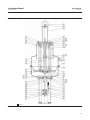
1
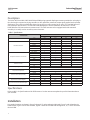
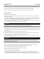
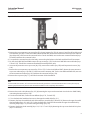
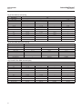
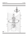
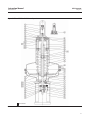
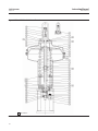
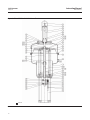
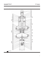
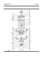
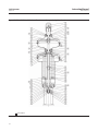
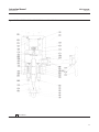
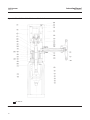
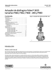
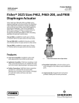
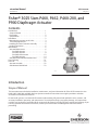
Instruction Manual
3025 Actuator
D251402X012
May 2011
Fisherr 3025 Sizes P460, P462, P460-200, and
P900 Diaphragm Actuator
Contents
Figure 1. Fisher 3025 Size P460-200 Actuator
Introduction . . . . . . . . . . . . . . . . . . . . . . . . . . . . . . . . . 1
Scope of Manual . . . . . . . . . . . . . . . . . . . . . . . . . . . . . 1
Description . . . . . . . . . . . . . . . . . . . . . . . . . . . . . . . . . 2
Specifications . . . . . . . . . . . . . . . . . . . . . . . . . . . . . . . 2
Installation . . . . . . . . . . . . . . . . . . . . . . . . . . . . . . . . . . . 2
Mounting the Actuator on the Valve . . . . . . . . . . . . 3
Travel Stop Adjustment . . . . . . . . . . . . . . . . . . . . . . . 4
Installing the Stem Connector Assembly . . . . . . . . . 5
Loading Connection . . . . . . . . . . . . . . . . . . . . . . . . . . 6
Maintenance . . . . . . . . . . . . . . . . . . . . . . . . . . . . . . . . . 6
Actuator Maintenance . . . . . . . . . . . . . . . . . . . . . . . . 6
Size P460 Actuator . . . . . . . . . . . . . . . . . . . . . . . 7
Size P462 Actuator . . . . . . . . . . . . . . . . . . . . . . . 9
Size P460-200 Actuator . . . . . . . . . . . . . . . . . . 12
Size P900 Actuator . . . . . . . . . . . . . . . . . . . . . . 14
Side Mounted Handwheel Maintenance . . . . . . . . . 18
Parts Ordering . . . . . . . . . . . . . . . . . . . . . . . . . . . . . . . 21
Parts List . . . . . . . . . . . . . . . . . . . . . . . . . . . . . . . . . . . 22
Actuator Assembly . . . . . . . . . . . . . . . . . . . . . . . . . . 22
Side-Mounted Handwheel . . . . . . . . . . . . . . . . . . . . 23
W9088
Introduction
Scope of Manual
This instruction manual includes installation, maintenance, and parts information for Fisher 3025 actuators in sizes
P460, P462, P460-200, and P900. Refer to separate manuals for instructions covering the positioner and other
accessories used with these actuators.
Do not install, operate, or maintain 3025 actuators without being fully trained and qualified in valve, actuator, and
accessory installation, operation, and maintenance. To avoid personal injury or property damage, it is important to
carefully read, understand, and follow all the contents of this manual, including all safety cautions and warnings. If you
have any questions about these instructions, contact your Emerson Process Management sales office before
proceeding.
www.Fisher.com
Instruction Manual
3025 Actuator
May 2011
D251402X012
Description
The Fisher 3025 size P460, P462, P460-200 and P900 spring-opposed diaphragm actuators position the valve plug in
the valve body in response to varying controller or valve positioner pneumatic output signals applied to the actuator
diaphragm. They can be specified either direct (air-to-close) or reverse acting (air-to-open). The size P460 offers 65
mm maximum actuator travel. The sizes P462 and P900 provide 120 mm maximum actuator travel. The size
P460-200 offers 203 mm maximum actuator travel. The 3025 actuator can be equipped with a side-mounted
assembly. It is usually used as an auxiliary manual actuator.
Table 1. Specifications
ACTUATOR SIZE
SPECIFICATION
Nominal Effective Area
Yoke Boss Diameter
Acceptable Valve Stem Connection
Maximum Travel
Maximum Diaphragm Casing Pressure
Temperature Capabilities
Pressure Connections (female)
Approximate Actuator Weights
Approximate Side Handwheel Weights
P460
P462
P460-200
P900
cm2
1800
1800
1800
3600
inch2
279
279
279
558
3-9/16 inch
x
x
x
---
5 inch
x
x
x
x
5H inch
x
x
x
x
75 mm
x
x
---
--x
120 mm
x
x
---
130 mm
---
---
---
x
3/4-16UNF
x
x
x
--x
1-14UNS
x
x
x
1-1/4-12UNF
x
x
x
x
M16
x
x
---
---
M20
x
x
---
x
M30
x
x
---
x
mm
65
120
203
120
inch
2-5/8
4-3/4
8
4-3/4
x
bar
4
Psig
58
_C
-30 to 80_C
_F
-22 to 176_F
1/2 NPT
x
x
x
3/4 NPT
x
x
---
x
1 NPT
---
---
x
---
kg
140
190
250
430
lb
310
420
640
1000
kg
40
40
100
65
lb
90
90
220
140
Specifications
Refer to table 1 for Specifications of the 3025 actuator. See the actuator nameplate for specific information about
your actuator.
Installation
Key number locations are shown in figures 3 through 12, unless otherwise indicated. Figures 3 and 4 show the size
P460 actuator, figures 5 and 6 the size P462, figures 7 and 8 the size P460-200 and figures 9, 10, 11 and 12 illustrate
the size P900.
2
Instruction Manual
D251402X012
3025 Actuator
May 2011
If the actuator is equipped with a side-mounted handwheel, also refer to the figures 13, 14, 15 and 16. Figure 13
shows the size P460 and the size P462 side-mounted handwheel, figure 14 the size P460-200 and figure 15 illustrates
the size P900.
CAUTION
To avoid parts damage, do not use a normal operating pressure that exceeds the Maximum Diaphragm Casing Pressure of 4
bar or produces a force on the actuator stem greater than the Maximum Allowable Valve Stem Load.
D Valve/Actuator Assembly: If the actuator and valve are shipped together as a control valve assembly, it has been
adjusted at the factory, and may be installed in the pipeline. After installing the valve in the pipeline, refer to the
Loading Connection procedures.
D Actuator Mounting: If the actuator is shipped separately or the actuator has been removed from the valve, it is
necessary to mount the actuator on the valve before placing the valve in the pipeline. Refer to the actuator
mounting procedures before placing the valve in service.
D Positioner: If a positioner is installed, or is to be installed on the actuator, refer to the positioner instruction manual
for installation. During the adjustment procedures, it will be necessary to provide a temporary loading pressure to
the actuator diaphragm.
CAUTION
The 3025 diaphragm actuators are designed to mount on push-down-to close valves. Do not mount these actuators on any
other type of valve without first contacting your Emerson Process Management sales office.
Mounting the Actuator on the Valve
CAUTION
If the valve stem is allowed to remain in the up position (towards the actuator) during mounting, it can interfere with the
actuator mounting, possibly damage valve stem threads or bend the valve stem. Be sure the valve stem is pushed down
(into the valve body), away from the actuator while mounting.
CAUTION
If the actuator is equipped with a side-mounted handwheel, during mounting it can interfere with the valve stem (even if
the valve stem is pushed completely down into the valve body), possibly damage valve stem threads or bend the valve
stem. Be sure the actuator stem is sufficiently retracted (into the side-mounted handwheel), away from the valve while
mounting. If not, the actuator stem can be retracted by turning counterclockwise the handwheel. Be sure the actuator
stem does not rotate while turning the handwheel (use the anti-rotator to prevent rotation).
1. Provide a vise or some other method of supporting the valve and the weight of the actuator during assembly. Push
the valve stem down away from the actuator while mounting the actuator.
3
3025 Actuator
May 2011
Instruction Manual
D251402X012
2. Lift or hoist the actuator onto the valve bonnet:
a. For the 3-9/16 yoke boss: Slowly lower the actuator down onto the valve. As the yoke passes over the end of the
valve stem, place the yoke locknut over the valve stem. Once the actuator is in place, screw the yoke locknut
onto the valve bonnet and tighten the locknut.
b. For all other yoke bosses: Slowly lower the actuator down onto the valve. Once the actuator is in place, insert the
cap screws and tighten the hex nuts, securing the actuator to the bonnet.
Travel Stop Adjustment
The actuator is normally shipped adjusted at the factory and you may refer directly to the Installing the Stem
Connector Assembly procedures.
If the actuator has been disassembled, it is necessary to adjust the travel stop. You may perform the following
procedure before connecting the actuator stem to the valve stem.
WARNING
When moving the actuator stem with loading pressure applied, exercise caution to keep hands and tools out of the
actuator stem travel path. If the loading pressure is accidentally disconnected, personal injury and property damage is
possible if something is caught between the actuator stem and other control valve parts.
Also provide a certified pressure gauge suitable to accurately read the diaphragm pressure from 0 through the upper
bench set pressure marked on the nameplate. Apply loading pressure to the diaphragm.
Stroke the actuator a few times to ensure that the pressure gauge is working correctly, and that the actuator is
functioning properly. It is important to be sure that the actuator assembly is not binding or producing any loading
friction on the actuator stem movement.
Note
For push-down-to-close valves, the valve plug is the limit for downward travel and the actuator up-stop is the limit for upward
travel (away from the valve).
1. If not already accomplished, provide a temporary means of applying adjustable loading pressure to the actuator
during the travel stop adjustments.
2. Remove the cap (key 43, figures 3 through 6) or loosen the locknut (key 42, figures 7 through 12). Unscrew the
travel stop (key 41).
3. Perform one of the following procedures as appropriate:
a. For an air-to-open actuator: apply the upper bench set loading pressure to the diaphragm. Adjust the travel stop
(key 41) so that it touches the actuator stem. Then lock the travel stop by replacing the cap (key 43) or by
tightening the locknut (key 42).
b. For an air-to-close actuator: apply the lower bench set loading pressure. The actuator should show movement at
the lower bench set pressure. Adjust the travel stop (key 41) so that it touches the actuator stem. Then lock the
travel stop by replacing the cap (key 43) or tightening the locknut (key 42).
4. Stroke the actuator and check that the actuator is capable of the travel shown on the travel indicator scale (key 74).
If the travel span is correct, travel stop adjustment is complete. Proceed to the Installing the Stem Connector
Assembly subsection.
4
Instruction Manual
D251402X012
3025 Actuator
May 2011
5. If the travel span is not correct, a wrong or damaged spring has been installed in the actuator. To obtain the correct
spring sizing information, refer to Fisher Catalog 14, Actuator Sizing and Sample Calculations to determine the
correct spring selection for your application. Or contact your Emerson Process Management sales office for
assistance. After replacing the spring, repeat the steps above.
Installing the Stem Connector Assembly
When installing the stem connector assembly, the actuator and valve stem threads should engage the threads of the
stem connector by a distance of the
diameter of the stem.
1. If necessary, push the valve stem down so that it is touching the seat ring.
2. For an air-to-open actuator only, set the diaphragm loading pressure to approximately 0.5 bar over the upper
bench set pressure. The actuator stem should be contacting the upper travel stop.
3. For the size P900 only, screw the actuator and valve stem locknuts away from the connector halves locations.
4. Screw the two stem connectors halves (keys 78 and 79) onto the valve stem and actuator stem. Then place the
travel indicator (key 84), the spacer if used (key 86) and the anti-rotator (key 85) on the valve stem connector half.
5. To adjust the travel, perform one of the following procedures as appropriate:
a. If the actuator is equipped with a side-mounted handwheel: turn the handwheel so that the distance between
the anti-rotator and the actuator stem connector half is equal to the valve travel. Be sure the actuator stem does
not rotate while turning the handwheel (use the anti-rotator to prevent rotation). Be sure that the actuator and
valve stem threads are engaging the threads of the stem connectors by the distance of at least one diameter of
the stem.
b. If the actuator is not equipped with a side-mounted handwheel: rotate the connector halves so that the distance
between the anti-rotator and the actuator stem connector half is equal to the valve travel. Be sure that the
actuator and valve stem threads are engaging the threads of the stem connectors by the distance of at least one
diameter of the stem.
CAUTION
Incomplete engagement of the stem connector onto either the valve stem or actuator stem can result in stripped threads
or improper operation. Be sure that the length of the actuator stem or the valve stem in the connector is equal or greater
than the diameter of that stem. Damage to threads on either stem or in the stem connector can cause the parts to be
replaced prematurely.
6. Perform one of the following procedures as appropriate:
a. For an air-to-open actuator: Slowly decrease the diaphragm pressure and line up the stem connector halves.
b. For an air-to-close actuator: Slowly increase the diaphragm pressure and line up the stem connector halves.
7. Install the cap screws (key 87) with the lock washers if used and tighten them.
8. For sizes P460, P462 and P460-200, install the cap screws (key 80) and the nuts (key 81) and tighten them. For the
size P900, screw the valve and actuator stem locknuts against the stem connector halves.
9. Slowly increase and decrease pressure several times, stroking the valve from the lower bench set pressure to the
upper pressure.
10. Adjust the travel indicator scale (key 74) to correspond with the travel indicator. Stroke the valve full travel to
ensure that the travel matches the valve travel on the travel indicator plate. If travel is not correct repeat the stem
connector procedure.
5
3025 Actuator
May 2011
Instruction Manual
D251402X012
11. If the actuator is equipped with a side-mounted handwheel, insert the screw (key 139) and the nut (key 140) into
the stem connector half (key 78). Then screw the nut against the stem connector half. Adjust the handwheel travel
indicator (key 113) to correspond with the screw (key 139) used as neutral position indicator. It may be necessary
to take off the protective covers (key 119) by removing the cap screws and washers (keys 120 and 128). Once
adjusted, replace the protective covers, washers and tighten the screws.
Loading Connection
The loading pressure connections are made at the factory if the valve, actuator, and positioner come as a unit. Keep
the length of tubing or piping as short as possible to avoid transmission lag in the control signal. If a volume booster,
valve positioner or other accessory is used, be sure that it is properly connected to the actuator. Refer to the positioner
instruction manual or other manuals as necessary.
For actuators shipped separately or whenever the actuator pressure connections are installed, use the following steps:
1. Connect the loading pressure piping to the NPT internal connection at the side of the diaphragm casing.
2. Cycle the actuator several times to be sure that the valve stem travel is correct when the correct pressure ranges
are applied to the diaphragm.
3. If valve stem travel appears to be incorrect, refer to the travel stop adjustment procedures at the beginning of this
section. Do not place the valve in service if it is not reacting correctly to diaphragm loading pressure changes.
Maintenance
Actuator parts are subject to normal wear and must be inspected and replaced when necessary. The frequency of
inspection and replacement depends on the severity of service conditions.
WARNING
Avoid personal injury or property damage from sudden release of process pressure or bursting of parts. Before performing
any maintenance operations:
D Do not remove the actuator from the valve while the valve is still pressurized.
D Disconnect any operating lines providing air pressure, electric power, or a control signal to the actuator. Be sure the
actuator cannot suddenly open or close the valve.
D Use bypass valves or completely shut off the process to isolate the valve from process pressure. Relieve process pressure
from both sides of the valve. Drain the process media from both sides of the valve.
D Vent the power actuator loading pressure and relieve any actuator spring precompression.
D Use lock-out procedures to be sure that the above measures stay in effect while you work on the equipment.
When performing maintenance procedures, isolate the control valve from the process line pressure from both sides of
the valve. Use the lock-out procedures to be sure that the above measures stay in effect while you are working on the
actuator.
Actuator Maintenance
This procedure describes how the actuator can be completely disassembled and assembled. When inspection or
repairs are required, disassemble only those parts necessary to accomplish the job; then, start the assembly at the
appropriate step.
6
Instruction Manual
D251402X012
3025 Actuator
May 2011
Key numbers refer to figures 3 through 12 unless otherwise indicated. Figure 3 and 4 show the size P460, figure 5 and
6 the size P462, figure 7 and 8 the size P460-200 and figures 9 through 12 illustrate the size P900.
It may be necessary to apply a temporary loading pressure to the actuator during the disassembly.
Size P460 Actuator
Size P460 Actuator Disassembly
1. Bypass the control valve. Reduce the loading pressure to atmospheric, and remove the tubing or piping from the
diaphragm casing (key 1).
2. If the actuator is equipped with a side-mounted handwheel, refer to the Side-Mounted Handwheel Disassembly
procedures in the Side-Mounted Handwheel Maintenance section to separate the actuator and handwheel (steps 2
to 7). Then continue the Size P460 Actuator Disassembly procedure from the step 8.
3. For an air-to-open actuator only: slightly pressurize the actuator diaphragm until movement of the actuator stem is
detected and the spring force applied to the stem connector is relieved.
WARNING
To avoid personal injury due to sudden uncontrolled movement of parts, do not loosen yoke locknut or cap screws and do
not remove parts of the stem connector when the stem connector has spring force applied to it.
4. Remove the stem connector cap screws (key 87), the anti-rotator (key 85), the spacer if used (key 86) and the travel
scale indicator (key 84). Loosen the stem connector halves cap screws and nuts (keys 80 and 81). Remove the stem
connector halves.
5. For an air-to-open actuator only: slowly exhaust the diaphragm pressure.
6. To separate the actuator from the valve body, remove the yoke locknut or the bolts and then lift off the actuator.
7. Remove the yoke cap screws (key 77) and then lift the actuator off the yoke.
8. Remove the lifting lug cap screws (key 44), the lifting lug (key 40) and the gasket (key 71). If required remove the
cap (key 43) and the travel stop (key 41).
WARNING
To avoid personal injury from the precompressed spring force thrusting the diaphragm casing away from the actuator,
carefully remove casing cap screws and nuts (keys 45 and 46) (step 9 below) and then relieve the spring compression by
unscrewing the nut (key 16) (step 11 below).
9. Remove all the diaphragm casing cap screws and nuts (keys 45 and 46). If required remove the vent (key 49).
10. Remove the set screws (key 57) and if used the travel stop and locknut (keys 65 and 66).
11. Relieve the spring compression by unscrewing slowly the nut (key 16).
12. Remove the washer (key 53), then lift off the diaphragm casing (key 3).
13. Remove the actuator springs (keys 30 and 31).
14. Lift off the stem and diaphragm plate assembly.
15. Unscrew the travel stop (key 54), remove ring (key 17), the wave washers (key 12), the tube (key 51), the
diaphragm plate (key 26), the diaphragm (key 47), the O-ring (key 6), the washers if used (key 64) and the travel
stop (key 14). Unbend the tab washer (key 13), remove the retaining ring (key 11) and the two nut halves (key 10).
7
3025 Actuator
May 2011
Instruction Manual
D251402X012
16. From the diaphragm casing (key 1) remove the retaining ring (key 8), the wiper ring and the seal retainer (keys 4
and 5) and the O-ring (key 6).
17. If required remove the casing bushings (keys 7 and 33), the pins (key 28) from the diaphragm casing and
diaphragm plate, the hellicoils (key 58), the travel scale, screw and nuts (keys 74, 75 and 76).
Size P460 Actuator Assembly
1. If removed, coat the bushings (keys 7 and 33) with lithium grease (key 201) and slide them into the diaphragm
casings.
2. Place the wiper ring (key 4) into the seal retainer (key 5). Apply lithium grease (key 201) to the O-ring (key 6), the
wiper ring and seal retainer assembly and install them into the diaphragm casing (key 1). Then place the retaining
ring (key 8).
3. If removed, insert the pins (key 28) into the diaphragm casing (key 3) and diaphragm plate (key 26).
4. If removed, insert the hellicoils (key 58) into the nut (key 16).
5. Coat the threads of the stem (key 9) with anti-seize lubricant (key 202).
6. Apply anti-seize lubricant (key 202) to the internal thread of the two nut halves (key 10). Install the nut halves and
the retaining ring (key 11). Place the tab washer (key 13) and bend it on the retaining ring. Slide the travel stop (key
14), the washers if used (key 64), the O-ring (key 6), the diaphragm (key 47), the diaphragm plate (key 26), the tube
(key 51), the wave washers (key 12) and the ring (key 17).
7. Coat the internal thread of the travel stop (key 54) with anti-seize lubricant (key 202), screw it onto the stem and
tighten until the wave washers are completely compressed.
8. Place this stem assembly into the diaphragm casing (key 1). Take care when pushing the actuator stem through the
diaphragm casing so that the threads do not damage the bushing, O-ring or wiper ring.
9. Place the actuator springs (keys 30 and 31).
10. Install the diaphragm casing (key 3) so that the vent and air connections are diametrically opposed. Take care
when lowering the casing around the stem so that the thread do not damage the bushing. Apply lithium grease
(key 201) to the washer (key 53) and place it.
11. Apply anti-seize lubricant (key 202) on the nut internal thread (key 16) and screw it slowly to compress the springs
until the two diaphragm casings touch the diaphragm.
Note
When you replace actuator diaphragms in the field, take care to ensure the diaphragm casing bolts are tightened to the proper
load to prevent leakage, but not crush the material. Perform the following sequence with a manual torque wrench.
CAUTION
Over-tightening the diaphragm cap screws and nuts (keys 45 and 46) can damage the diaphragm. Do not exceed 16 NSm
(12 lbfSft) torque.
Note
Do not use lubricant on these bolts and nuts. Fasteners must be clean and dry.
12. Align the diaphragm casings and diaphragm holes. Be sure the vent and air connections on the diaphragm casings
are still diametrically opposed. Install the cap screws and nuts (keys 45 and 46). Tighten the diaphragm cap screws
and nuts in the following manner.
8
Instruction Manual
D251402X012
3025 Actuator
May 2011
13. The first four bolts tightened should be diametrically opposed and 90 degrees apart. Tighten these four bolts to 8
NSm (6 lbfSft).
14. Tighten the remaining bolts in a clockwise, crisscross pattern to 8 NSm (6 lbfSft).
15. Repeat this procedure by tightening four bolts, diametrically opposed and 90 degrees apart, to a torque of 16
NSm (12 lbfSft).
16. Tighten the remaining bolts in a clockwise, crisscross pattern to 16 NSm (12 lbfSft).
17. After the last bolt is tightened to 16 NSm (12 lbfSft) all of the bolts should be tightened again to 16 NSm (12 lbfSft)
in a circular pattern around the bolt circle.
18. Once completed, no more tightening is recommended.
19. Tighten the set screws (key 57) into the nut (16).
20. If used, place the locknut and travel stop on the stem (keys 65 and 66) and screw the locknut against the travel
stop.
21. Place the gasket (71) and the lifting lug cap (40) onto one of the diaphragm casings according to the actuator
action (air-to-close: key 1, air-to-open: key 3). Insert the cap screws (key 44) and tighten them.
22. If removed, place the travel stop (key 41) into the lifting lug cap.
23. If the actuator is equipped with a side-mounted handwheel, it is necessary to adjust the actuator travel stop
before mounting the actuator onto the side-mounted handwheel. Perform the Travel Stop Adjustment in
accordance with the procedures in the Installation section. Then refer to the Side-Mounted Handwheel Assembly
procedures in the Side- Mounted Handwheel Maintenance section to complete the actuator assembly (from step
9).
24. Lift the actuator and place it onto the yoke. Insert the cap screws (key 77) and tighten them.
25. If removed, screw the vent (key 49) into the diaphragm casing (key 3).
26. Mount the actuator onto the valve in accordance with the procedures in the Installation section.
Size P462 Actuator
Size P462 Actuator Disassembly
1. Bypass the control valve. Reduce the loading pressure to atmospheric, and remove the tubing or piping from the
diaphragm casing (key 1).
2. If the actuator is equipped with a side-mounted handwheel, refer to the Side-Mounted Handwheel Disassembly
procedures in the Side-Mounted Handwheel Maintenance section to separate the actuator and handwheel (steps 2
to 7). Then continue the Size P462 Actuator Disassembly procedure from the step 8.
3. For an air-to-open actuator only: slightly pressurize the actuator diaphragm until movement of the actuator stem is
detected. The spring force applied to the stem connector is relieved.
WARNING
To avoid personal injury due to sudden uncontrolled movement of parts, do not loosen yoke locknut or cap screws and do
not remove parts of the stem connector when the stem connector has spring force applied to it.
4. Remove the stem connector cap screws (key 87), the anti-rotator (key 85), the spacer if used (key 86) and the travel
scale indicator (key 84). Loosen the stem connector halves cap screws and nuts (keys 80 and 81). Remove the stem
connector halves.
5. For an air-to-open actuator only: slowly exhaust the diaphragm pressure.
6. To separate the actuator from the valve body, remove the yoke locknut or the bolts and then lift off the actuator.
9
3025 Actuator
Instruction Manual
May 2011
D251402X012
7. Remove the yoke cap screws (key 77), then lift the actuator off the yoke.
8. Remove the lifting lug cap screws (key 44), the lifting lug (key 40), the gasket (key 71) and the spacer if used (key
67). If required remove the cap (key 43) and the travel stop (key 41).
9. Unscrew the cap screws (key 36) and remove the flange (key 34) and gasket (key 72).
10. Unbend the ring retaining (key 59) and slide towards the casing. Remove the 2 ring halves (key 61) and then the
ring retaining.
WARNING
To avoid personal injury from the precompressed spring force thrusting the diaphragm casing away from the actuator,
relieve the spring compression (step 11 below) and carefully remove casing cap screws and nuts (keys 45 and 46) (step 12
below)
11. Relieve the spring compression by unscrewing alternately and slowly the four cap screws (key 32).
12. Remove all the diaphragm casing cap screws and nuts (keys 45 and 46). If required remove the vent (key 49).
13. Lift off the diaphragm casing (key 3).
14. Remove the spring seat (key 29) and actuator spring (key 30).
15. Lift off the stem and diaphragm plate assembly.
16. Unscrew the set screw (key 57) and remove the travel stop (key 52). Loosen the nut (key 10). Remove the ring
retaining (key 11), the wave washers (key 12), the tube (key 51), the diaphragm plate (key 26), the diaphragm (key
47), the O-ring (key 6), the travel stop (key 14), the ring retaining (key 60) and the 2 ring halves.
17. From the diaphragm casing (key 1) remove the retaining ring (key 8), the wiper ring and the seal retainer (keys 4
and 5) and the O-ring (key 6).
18. If required, remove the casing bushings (keys 7 and 33), the pins (key 28) from the diaphragm plate and spring
seat, thread the travel stop if used
(key 66) out of the stem. If required, remove the travel scale, the screws and nuts (keys 74, 75 and 76).
Size P462 Actuator Assembly
1. If removed, coat the bushings (keys 7 and 33) with lithium grease (key 201) and slide them into the diaphragm
casings.
2. Place the wiper ring (key 4) into the seal retainer (key 5). Apply lithium grease (key 201) to the O-ring (key 6), the
wiper ring and seal retainer assembly and install them into the diaphragm casing (key 1). Then place the retaining
ring (key 8).
3. If removed, insert the pins (key 28) into the spring seat (key 29) and diaphragm plate (key 26).
4. Coat the threads of the stem (key 9) with anti-seize lubricant (key 202).
5. Place the two ring halves (key 61) and the retaining ring (key 60). Slide the travel stop (key 14), the O-ring (key 6),
the diaphragm (key 47), the diaphragm plate (key 26), the tube (key 51), the wave washers (key 12) and the
retaining ring (key 11).
6. Coat the internal thread of the 2 nut halves (key 10) with anti-seize lubricant (key 202) and tighten them until the
wave washers are completely compressed.
7. Slide the travel stop (key 52) and tighten the set screw (key 57).
8. Place this stem assembly into the diaphragm casing (key 1). Take care when pushing the actuator stem through the
diaphragm casing so that the threads do not damage the bushing, O-ring or wiper ring.
9. Place the actuator spring (key 30). Apply anti-seize lubricant (key 202) into the four cap screw beds of the spring
seat. Place the spring seat (key 29) so that the cap screw beds will be aligned with the internal threads of the
diaphragm casing (key 3).
10
Instruction Manual
D251402X012
3025 Actuator
May 2011
10. Install the diaphragm casing (key 3) so that the vent and air connection are diametrically opposed. Take care when
lowering the casing around the stem so that the threads do not damage the bushing.
Note
When you replace actuator diaphragms in the field, take care to ensure the diaphragm casing bolts are tightened to the proper
load to prevent leakage, but not crush the material. Perform the following sequence with a manual torque wrench.
CAUTION
Over-tightening the diaphragm cap screws and nuts (keys 45 and 46) can damage the diaphragm. Do not exceed 16 NSm
(12 lbfSft) torque.
Note
Do not use lubricant on these bolts and nuts. Fasteners must be clean and dry.
11. Align the diaphragm casings and diaphragm holes. Be sure the vent and air connection on the diaphragm casings
are still diametrically opposed. Install the cap screws and nuts (keys 45 and 46). Tighten the diaphragm cap screws
and nuts in the following manner.
12. The first four bolts tightened should be diametrically opposed and 90 degrees apart. Tighten these four bolts to 8
NSm (6 lbfSft).
13. Tighten the remaining bolts in a clockwise, crisscross pattern to 8 NSm (6 lbfSft).
14. Repeat this procedure by tightening four bolts, diametrically opposed and 90 degrees apart, to a torque of 16
NSm (12 lbfSft).
15. Tighten the remaining bolts in a clockwise, crisscross pattern to 16 NSm (12 lbfSft).
16. After the last bolt is tightened to 16 NSm (12 lbfSft) all of the bolts should be tightened again to 16 NSm (12 lbfSft)
in a circular pattern around the bolt circle.
17. Once completed, no more tightening is recommended.
18. Coat the thread of the four cap screws (key 32) and the internal threads of the diaphragm casing (key 3) with
anti-seize lubricant (key 202). Be sure that the cap screw beds into the spring seat are still aligned with the internal
threads of the diaphragm casing. Then install and screw alternately and slowly the four cap screws to compress the
spring.
19. Place the retaining ring (key 59) onto the stem. Install the ring (key 61) and slide the retaining ring and bend it on
the ring.
20. Place the gasket (key 72) and the flange (key 34). Insert the cap screws (key 36) and tighten them.
21. If used, screw travel stop on the stem (keys 66).
22. Place the spacer if used (key 67), the gasket (key 71) and the lifting lug cap (key 40) onto one of the diaphragm
casings according to the actuator action (air-to-close: key 1, air-to-open: key 3). Insert the cap screws (key 44) and
tighten them.
23. If removed, place the travel stop (key 41) into the lifting lug cap.
24. If the actuator is equipped with a side-mounted handwheel, it is necessary to adjust the actuator travel stop
before mounting the actuator onto the side-mounted handwheel. Perform the Travel Stop Adjustment in
accordance with the procedures in the Installation section. Then refer to the Side-Mounted Handwheel Assembly
11
3025 Actuator
Instruction Manual
May 2011
D251402X012
procedures in the Side- Mounted Handwheel Maintenance section to complete the actuator assembly (from step
9).
25. Lift the actuator and place it onto the yoke. Insert the cap screws (key 77) and tighten them.
26. If removed, screw the vent (key 49) into the diaphragm casing (key 3).
27. Mount the actuator onto the valve in accordance with the procedures in the Installation section.
Size P460-200 Actuator
Size P460-200 Actuator Disassembly
1. Bypass the control valve. Reduce the loading pressure to atmospheric, and remove the tubing or piping from the
diaphragm casing (key 1).
2. If the actuator is equipped with a side-mounted handwheel, refer to the Side-Mounted Handwheel Disassembly
procedures in the Side-Mounted Handwheel Maintenance section to separate the actuator and handwheel (steps 2
to 7). Then continue the Size P460-200 Actuator Disassembly procedure from the step 8.
3. For an air-to-open actuator only: slightly pressurize the actuator diaphragm until movement of the actuator stem is
detected. The spring force applied to the stem connector is relieved.
WARNING
To avoid personal injury due to sudden uncontrolled movement of parts, do not loosen yoke locknut or cap screws and do
not remove the parts of the stem connector when the stem connector has spring force applied to it.
4. Remove the stem connector cap screws (key 87), the anti-rotator (key 85), the spacer if used (key 86) and the travel
scale indicator (key 84). Loosen the stem connector halves cap screws and nuts (keys 80 and 81). Remove the stem
connector halves.
5. For an air-to-open actuator only: slowly exhaust the diaphragm pressure.
6. To separate the actuator from the valve body, remove the yoke locknut or the bolts and then lift off the actuator.
7. Remove the yoke cap screws (key 77), then lift the actuator off the yoke.
8. Remove the bellows (key 68). Remove the lifting lug cap screws (key 44), the lifting lug (key 40) and the gasket (key
71). If required, loosen the locknut (key 42) and remove the travel stop (key 41).
WARNING
To avoid personal injury from the precompressed spring force thrusting the diaphragm casing away from the actuator,
carefully remove casing cap screws and nuts (keys 45 and 46) (step 9 below) and then relieve the spring compression by
unscrewing the nut (key 16) (step 11 below).
9. Remove all the diaphragm casing cap screws and nuts (keys 45 and 46). If required remove the vent (key 49).
10. Unscrew the locknut (key 62).
11. Relieve the spring compression by unscrewing slowly the nut (key 16).
12. Remove the washer (key 53), then lift off the diaphragm casing (key 3).
13. Remove the actuator springs (keys 30 and 31).
14. Lift off the stem and diaphragm plate assembly.
15. Unscrew the travel stop (key 54), remove the wave washers (key 12), the tube (key 51), the O-ring (key 6), the
diaphragm and diaphragm plate assembly (keys 24, 25, 26 and 47). Remove the retaining ring (key 11) and the two
nut halves (key 10).
12
Instruction Manual
3025 Actuator
D251402X012
May 2011
16. Unscrew the cap screws (key 25), disassemble the ring (key 24), the diaphragm (key 47) and the diaphragm plate
(key 26).
17. Unscrew the cap screws (key 70), remove the wiper ring and the seal retainer (key 4 and 5) and the O-ring (key 6).
18. If required, remove the casing bushings (keys 7 and 33) and the pins (key 28) from the diaphragm plate and
casing. If required, remove the travel scale, screw and nuts (keys 74, 75 and 76).
Size P460-200 Actuator Assembly
1. If removed, coat the bushings (keys 7 and 33) with lithium grease (key 201) and slide them into the diaphragm
casings.
2. Place the wiper ring (key 4) into the seal retainer (key 5). Apply lithium grease (key 201) to the O-ring (key 6), the
wiper ring and seal retainer assembly and install them into the diaphragm casing (key 1). Then insert the cap screws
(key 70) and tighten them.
3. If removed, insert the pins (key 28) into the diaphragm casing (key 3) and diaphragm plate (key 26).
4. Place the diaphragm (key 47) on the diaphragm plate (key 26). Install the ring (key 24) and the cap screws (key 25)
and tighten them.
5. Coat the threads of the stem (key 9) with anti-seize lubricant (key 202).
6. Apply anti-seize lubricant (key 202) to the internal thread of the two nut halves (key 10). Install the nut halves and
the retaining ring (key 11). Slide the diaphragm and diaphragm plate assembly (keys 24, 25, 26 and 47), the O-ring
(key 6), the tube (key 51), the wave washers (key 12).
7. Coat the internal thread of the travel stop (key 54) with anti-seize lubricant (key 202), screw it onto the stem and
tighten until the wave washers are completely compressed.
8. Place this stem assembly into the diaphragm casing (key 1). Take care when pushing the actuator stem through the
diaphragm casing so that the threads do not damage the bushing, O-ring or wiper ring.
9. Place the actuator springs (key 30 and 31).
10. Install the diaphragm casing (key 3) so that the vent and air connection are diametrically opposed. Take care when
lowering the casing around the stem so that the thread do not damage the bushing. Apply lithium grease to the
washer (key 53) and place it.
11. Apply anti-seize lubricant (key 202) on the nut internal thread (key 16) and screw it slowly to compress the
springs.
Note
When you replace actuator diaphragms in the field, take care to ensure the diaphragm casing bolts are tightened to the proper
load to prevent leakage, but not crush the material. Perform the following sequence with a manual torque wrench.
CAUTION
Over-tightening the diaphragm cap screws and nuts (keys 45 and 46) can damage the diaphragm. Do not exceed 16 NSm
(12 lbfSft) torque.
Note
Do not use lubricant on these bolts and nuts. Fasteners must be clean and dry.
13
3025 Actuator
Instruction Manual
May 2011
D251402X012
12. Align the diaphragm casings and diaphragm holes. Be sure the vent and air connection on the diaphragm casings
are still diametrically opposed. Install the cap screws and nuts (keys 45 and 46). Tighten the diaphragm cap screws
and nuts in the following manner.
13. The first four bolts tightened should be diametrically opposed and 90 degrees apart. Tighten these four bolts to 8
NSm (6 lbfSft).
14. Tighten the remaining bolts in a clockwise, crisscross pattern to 8 NSm (6 lbfSft).
15. Repeat this procedure by tightening four bolts, diametrically opposed and 90 degrees apart, to a torque of 16
NSm (12 lbfSft).
16. Tighten the remaining bolts in a clockwise, crisscross pattern to 16 NSm (12 lbfSft).
17. After the last bolt is tightened to 16 NSm (12 lbfSft) all of the bolts should be tightened again to 16 NSm (12 lbfSft)
in a circular pattern around the bolt circle.
18. Once completed, no more tightening is recommended.
19. Screw the locknut (key 62) against the nut (key 16).
20. Place the bellows (key 68 and 69).
21. Place the gasket (key 71) and the lifting lug cap (key 40) onto one of the diaphragm casings according to the
actuator action (air-to-close: key 1, air-to-open: key 3). Coat the cap screws (key 44) with lithium grease and
tighten them.
22. If removed, place the travel stop and the locknut (keys 41 and 42) into the lifting lug cap.
23. If the actuator is equipped with a side-mounted handwheel, it is necessary to adjust the actuator travel stop
before mounting the actuator onto the side-mounted handwheel. Perform the Travel Stop Adjustment in
accordance with the procedures in the Installation section. Then refer to the Side-Mounted Handwheel Assembly
procedures in the Side- Mounted Handwheel Maintenance section to complete the actuator assembly (from step
9).
24. Lift the actuator and place it onto the yoke. Insert the cap screws (key 77) and tighten them.
25. If removed, screw the vent (key 49) into the diaphragm casing (key 3).
26. Mount the actuator onto the valve in accordance with the procedures in the Installation section.
Size P900 Actuator
Size P900 Actuator Disassembly
1. Bypass the control valve. Reduce the loading pressure to atmospheric, and remove the tubing or piping from the
diaphragm casings (key 1).
2. If the actuator is equipped with a side-mounted handwheel, refer to the Side-Mounted Handwheel Disassembly
procedures in the Side-Mounted Handwheel Maintenance section to separate the actuator and handwheel (steps 2
to 7). Then continue the Size P900 Actuator Disassembly procedure from the step 8.
3. For an air-to-open actuator only: slightly pressurize the actuator diaphragm until movement of the actuator stem is
detected. The spring force applied to the stem connector is relieved.
WARNING
To avoid personal injury due to sudden uncontrolled movement of parts, do not loosen yoke cap screws and do not remove
the parts of the stem connector when the stem connector has spring force applied to it.
4. Remove the stem connector cap screws (key 87), the anti-rotator (key 85) and the spacer if used (key 86). Loosen
the stem connector halves locknuts (keys 82 and 83). Remove the stem connector halves.
5. For an air-to-open actuator only: slowly exhaust the diaphragm pressure.
14
Instruction Manual
3025 Actuator
D251402X012
May 2011
6. To separate the actuator from the valve body, remove the yoke locknut or the bolts and then lift off the actuator.
7. Remove the yoke-to-actuator cap screws (key 77), then lift the actuator off the yoke.
8. Remove the lifting lug cap screws (key 44), the lifting lug (key 40) and the gasket (key 71). If required, loosen the
locknut (key 42) and remove the travel stop (key 41).
9. Unscrew the cap screws (key 35) and remove the flange (key 34) and gasket (key 72).
10. Unbend the ring retaining (key 59) and slide towards the casing. Remove the 2 ring halves (key 61) and then the
ring retaining.
WARNING
To avoid personal injury from the precompressed spring force thrusting the diaphragm casing away from the actuator,
relieve the spring compression (step 11 below) and carefully remove casing cap screws and nuts (keys 45 and 46) (steps 12
and 16 below).
11. Relieve the spring compression by unscrewing alternately and slowly the three cap screws (key 32).
Note
The size P900 is a double stacked diaphragm casings actuator. First disassemble the stack composed of two short diaphragm
casings (keys 1 and 2). Then disassemble the stack made of one short and one long diaphragm casings (keys 1 and 3).
12. Remove all the cap screws and nuts (keys 45 and 46) of the short diaphragm casings assembly (keys 1 and 2). If
required, remove the vent (key 49).
13. Lift off the diaphragm casing (key 1).
14. Unscrew the nut (key 10). Remove the ring retaining (key 11), the washer (key 55), the O-ring (key 20), the
diaphragm (key 48), the diaphragm plate (key 27), the lock washer (key 50), the ring retaining (key 11) and the two
nut halves (key 10).
15. Remove the cap screws, the washers (keys 22 and 23) and the diaphragm casing (key 2).
16. Remove all the cap screws and nuts (keys 45 and 46) of the long diaphragm casings assembly (keys 1 and 3). If
required, remove the vent (key 49).
17. Lift off the diaphragm casing (key 3).
18. Remove the spring seat with the discs (keys 29 and 39) and actuator spring (key 30).
19. Lift off the stem and diaphragm plate assembly.
20. Unscrew the set screw (key 57) and remove the travel stop (key 52). Loosen the nut (key 10). Remove the ring
retaining (key 11), the wave washer (key 50), the tube if used (key 51), the diaphragm plate and diaphragm
assembly (keys 24, 25, 26 and 47), the O-ring (key 6), the travel stop assembly (keys 14, 15, 18 and 19), the
retaining (key 11) and the two nut halves (key 10).
21. Unscrew the cap screws (key 25), disassemble the ring (key 24), the diaphragm (key 47) and the diaphragm plate
(key 26).
22. If required, remove the cap screws (key 18), lock washers (key 19) and disassemble the travel stop (keys 14 and
15).
23. Unscrew the cap screws (key 21), remove the wiper ring and the seal retainer (keys 4 and 5) and the O-ring (key 6).
24. If required, remove the casing bushings (keys 7 and 33), the pins (key 28) from the diaphragm plate and spring
seat. If required, remove the travel scale, the screws and nuts (keys 74, 75 and 76).
Size P900 Actuator Assembly
1. If removed, coat the bushing (keys 7 and 33) with lithium grease (key 201) and slide them into the diaphragm
casings.
15
3025 Actuator
Instruction Manual
May 2011
D251402X012
2. Place the wiper rings (key 4) into the seal retainers (key 5). Apply lithium grease (key 201) to the O-rings (key 6), the
wiper ring and seal retainer assemblies and install them into the diaphragm casings (key 1). Then insert the cap
screws (key 21) and tighten them.
3. If removed, insert the pins (key 28) into the spring seat (key 29) and diaphragm plate (key 26).
4. Assemble the two travel stop parts (keys 14 and 15), install the lock washers (key 18) and the cap screws (key 18)
and tighten them.
5. Place the diaphragm (key 47) on the diaphragm plate (key 26). Install the ring (key 24) and the cap screws (key 25)
and tighten them.
Note
The size P900 is a double stacked diaphragm casings actuator. First assemble the stack made of a short and a long diaphragm
casing (keys 1 and 3). Then mount the stack composed of two short diaphragm casings (keys 1 and 2).
6. Coat the threads of the stem (key 9) with anti-seize lubricant (key 202).
7. Apply anti-seize lubricant (key 202) to the internal thread of the two nut halves (key 10). Install the nut halves and
the retaining ring (key 11). Slide the travel stop assembly (keys 14, 15, 18 and 19), the O-ring (key 6), the
diaphragm plate assembly (keys 24, 25, 26 and 47), the tube if used (key 51), the lock washer (key 50) and the ring
(key 11).
8. Coat the internal thread of the two nut halves (key 10) with anti-seize lubricant (key 202) and tighten them until the
lock washer is completely compressed.
9. Slide the travel stop (key 52) and tighten the set screws (key 57).
10. Place this stem assembly into the diaphragm casing (key 1). Take care when pushing the actuator stem through
the diaphragm casing so that the threads do not damage the bushing, O-ring or wiper ring.
11. Install the actuator springs (key 30 and 31). Apply anti-seize lubricant (key 202) into the three cap screw beds of
the spring seat. Coat the disc (key 39) with anti-seize lubricant (key 202). Install the discs into the spring seat and
place the spring seat so that the cap screw beds will be aligned with the internal threads of the diaphragm casing
(key 3).
12. Install the diaphragm casing (key 3) so that the vent and air connection are diametrically opposed. Take care when
lowering the casing around the stem so that the threads do not damage the bushing.
Note
When you replace actuator diaphragms in the field, take care to ensure the diaphragm casing bolts are tightened to the proper
load to prevent leakage, but not crush the material. Perform the following sequence with a manual torque wrench.
CAUTION
Over-tightening the diaphragm cap screws and nuts (keys 45 and 46) can damage the diaphragm. Do not exceed 16 NSm
(12 lbfSft) torque.
Note
Do not use lubricant on these bolts and nuts. Fasteners must be clean and dry.
16
Instruction Manual
D251402X012
3025 Actuator
May 2011
13. Align the diaphragm casings and diaphragm holes. Be sure the vent and air connection on the diaphragm casings
are still diametrically opposed. Install the cap screws and nuts (keys 45 and 46). Tighten the diaphragm cap screws
and nuts in the following manner.
14. The first four bolts tightened should be diametrically opposed and 90 degrees apart. Tighten these four bolts to 8
NSm (6 lbfSft).
15. Tighten the remaining bolts in a clockwise, crisscross pattern to 8 NSm (6 lbfSft).
16. Repeat this procedure by tightening four bolts, diametrically opposed and 90 degrees apart, to a torque of 16
NSm (12 lbfSft).
17. Tighten the remaining bolts in a clockwise, crisscross pattern to 16 NSm (12 lbfSft).
18. After the last bolt is tightened to 16 NSm (12 lbfSft) all of the bolts should be tightened again to 16 NSm (12 lbfSft)
in a circular pattern around the bolt circle.
19. Once completed, no more tightening is recommended.
20. Coat the thread of three cap screws (key 32) and the internal threads of the diaphragm casing (key 3) with
anti-seize lubricant (key 202). Be sure that the cap crew beds into the spring seat are still aligned with the internal
threads of the diaphragm casing. Then install and screw alternately and slowly the three cap screws to compress
the springs.
21. Place the retaining ring (key 59) onto the stem. Install the ring (key 61) and slide the retaining ring and bend it on
the ring.
22. Place the gasket (key 72) and the flange (key 34). Insert the cap screws (key 34) and tighten them.
23. Place the diaphragm casing (key 2) so that the vent connection is diametrically opposed to the air connection of
the diaphragm casing (key 1) next to. Install the lock washers (key 23) and the cap screws (key 22) and tighten
them.
24. Apply anti-seize lubricant (key 202) to the internal thread of the two nut halves (key 10). Install the nut halves and
the retaining ring (key 11). Slide the lock washer (key 50), the diaphragm plate (key 27), the diaphragm (key 48),
the O-ring (key 20), the washer (key 55), the retaining ring (key 11).
25. Coat the internal thread of the two nut halves (key 10) with anti-seize lubricant (key 202) and tighten them until
the lock washer is completely compressed.
26. Place the diaphragm casing (key 1) so that the vent and air connection are diametrically opposed. Take care when
sliding the diaphragm casing around the stem so that the threads do not damage the bushing, O-ring or wiper ring.
Note
When you replace actuator diaphragms in the field, take care to ensure the diaphragm casing bolts are tightened to the proper
load to prevent leakage, but not crush the material. Perform the following sequence with a manual torque wrench.
CAUTION
Over-tightening the diaphragm cap screws and nuts (keys 45 and 46) can damage the diaphragm. Do not exceed 16 NSm
(12 lbfSft) torque.
Note
Do not use lubricant on these bolts and nuts. Fasteners must be clean and dry.
17
3025 Actuator
Instruction Manual
May 2011
D251402X012
27. Align the diaphragm casings and diaphragm holes. Be sure the vent and air connection on the diaphragm casings
are still diametrically opposed. Install the cap screws and nuts (keys 45 and 46). Tighten the diaphragm cap screws
and nuts in the following manner.
28. The first four bolts tightened should be diametrically opposed and 90 degrees apart. Tighten these four bolts to 8
NSm (6 lbfSft).
29. Tighten the remaining bolts in a clockwise, crisscross pattern to 8 NSm (6 lbfSft).
30. Repeat this procedure by tightening four bolts, diametrically opposed and 90 degrees apart, to a torque of 16
NSm (12 lbfSft).
31. Tighten the remaining bolts in a clockwise, crisscross pattern to 16 NSm (12 lbfSft).
32. After the last bolt is tightened to 16 NSm (12 lbfSft) all of the bolts should be tightened again to 16 NSm (12 lbfSft)
in a circular pattern around the bolt circle.
33. Once completed, no more tightening is recommended.
34. Place the gasket (71) and the lifting lug cap (40) onto one of the diaphragm casings according to the actuator
action (air-to-close: key 1, air-to-open: key 3). Insert the cap screws (key 44) and tighten them.
35. If removed, place the travel stop and the lock nut (keys 41 and 42) into the lifting lug cap.
36. If the actuator is equipped with a side-mounted handwheel, it is necessary to adjust the actuator travel stop
before mounting the actuator onto the side-mounted handwheel. Perform the Travel Stop Adjustment in
accordance with the procedures in the Installation section. Then refer to the Side-Mounted Handwheel Assembly
procedures in the Side- Mounted Handwheel Maintenance section to complete the actuator assembly (from step
9).
37. Lift the actuator and place it onto the yoke. Insert the cap screws (key 77) and tighten them.
38. If removed, screw the vents (key 49) into the diaphragm casings (keys 2 and 3).
39. Mount the actuator onto the valve in accordance with the procedures in the Installation section.
Side-Mounted Handwheel Maintenance
Instructions are given below for complete disassembly and assembly of a side-mounted handwheel. Perform the
disassembly only as far as necessary to accomplish the required maintenance; then, begin the assembly at the
appropriate step.
If it is only necessary to separate the actuator from the side-mounted handwheel, perform the eight first steps of the
following Side-Mounted Handwheel Disassembly procedure. Then to mount the actuator on the side-mounted
handwheel begin at the step 9 of the Side-Mounted Handwheel Assembly procedure.
Key numbers refer to figures 13, 14, 15 and 16 unless otherwise indicated. Figure 13 shows the sizes P460 and P462
Handwheel, figure 14 the size P900, figure 15 the size P460-200 and figure 16 illustrates the driving shaft assembly.
It may be necessary to apply a temporary loading pressure to the actuator during the assembly.
Side-Mounted Handwheel Disassembly
1. Bypass the control valve. Reduce the actuator loading pressure to atmospheric, and remove the tubing or piping
from the diaphragm casing.
2. For an air-to-open actuator only: Turn counterclockwise until movement of the handwheel stem is detected. The
spring force applied to the stem connector is relieved.
WARNING
To avoid personal injury due to sudden uncontrolled movement of parts, do not loosen yoke cap screws and do not remove
the parts of the stem connector when the stem connector has spring force applied to it.
18
Instruction Manual
D251402X012
3025 Actuator
May 2011
Figure 2. Side Mounted Handwheel
3. Remove the stem connector cap screws (key 87), the anti-rotator (key 78), the spacer if used (key 86) and the travel
scale indicator (key 85). For the sizes P460, P462 and P460-200, loosen stem connector halves cap screws and nuts
(keys 80 and 81) and unscrew the connector halves. For the size P900, unscrew the stem connector locknuts (keys
82 and 83) and then the connector halves.
4. To separate the actuator from the valve body, remove the yoke locknut or the bolts and then lift off the actuator.
5. For the sizes P460, P462 and P900 remove the cap screws (key 122). For the size P460-200 remove the bolts (keys
122 and 132). Then lift the actuator and handwheel assembly off the yoke.
6. Unscrew the protective cover cap screws (key 120), remove the washers (key 128) and the protective covers (key
119).
7. Remove the stem connector cap screws (key 125 or 137). For the sizes P460 and P462, loosen the stem connector
cap screws and nuts (keys 130 and 131) and unscrew the connector half. For the sizes P900 and P460-200, unscrew
the stem connector locknut (key 136) and then the connector half (key 124).
8. Remove the cap screws (key 77), then lift the actuator off the handwheel.
Note
To disassemble the actuator, refer to the Actuator Disassembly procedures in the Actuator Maintenance section (from step 8).
Following steps describe only how the side-mounted handwheel can be completely disassembled.
9. Remove the travel scale indicator (key 113) by loosening the cap screw that maintain it or for the size P460-200 by
unscrewing the two nuts (key 129).
10. For the size P460-200, remove the two bellows (keys 133, 134 and 135).
11. Turn clockwise the handwheel to unscrew the upper threaded shaft (key 111).
12. Remove the lower threaded shaft and shaft connector assembly (keys 109 and 110). Remove the upper threaded
shaft and bridge (keys 111 and 112). For the size P460-200, if required disassemble the upper threaded shaft by
removing the pin (key 127) and unscrewing the bridge (key 112).
13. Remove the driving shaft assembly (keys 114, 116, 117 and 118) by loosening the cap screws that hold it in place
(keys 115 and 126).
19
3025 Actuator
Instruction Manual
May 2011
D251402X012
14. If required, the driving shaft assembly can be broken down by removing the nut (key 118), the washer (key 117),
the rotation indicator (key 114.5), the handwheel (key 116), and then the driving shaft (key 114.4) and the bearing
(key 114.3). If required, remove the cap screws and nuts (keys 114.9 and 114.10) of the anti-rotator clamped on
the driving shaft housing (key 114.1), the anti-rotator (key 114.7), the spacer (114.8) and the two clamps (key
114.6).
15. Remove the screws (key 108), the washer (key 107), the key (key 106), the gear ring (key 105) and the bearing
(key 104). If required, remove the bushing (key 103) from the gear housing (key 102).
Side-Mounted Handwheel Assembly
1. If the driving shaft assembly was separated, coat the bushings (key 114.2), the bearing (key 114.3) and the shaft
(key 114.4) with lithium grease (key 201). Place the bearing, and then insert the shaft into the housing (key 114.1).
Place the handwheel (key 116), the rotation indicator (key 114.5), the washer (key 117) and then insert and tighten
the nut (key 118). Place the two clamps (key 114.6), the spacer and the anti-rotator at the opposite (keys 114.7 and
114.8), insert the cap screws and nuts (key 114.9 and 114.10) and tighten them.
2. If removed, coat the bushing (key 103) with lithium grease (key 201) and slide it into the housing (key 102).
3. Coat the bushing (key 103), the bearing (key 104) and the gear ring (key 105) with lithium grease (key 201). Place
the gear housing (key 102) onto the yoke, install the bearing (key 104), and the gear ring (key 105).
4. Coat the thread of the shafts (keys 110 and 111) and the internal threads of the shaft connector (key 109) with
anti-seize lubricant (key 202). Insert the lower threaded shaft (key 110) into the shaft connector (key 109) by
engaging three or four threads.
5. For the size P460-200, if the upper threaded shaft (key 111) was separated from the bridge (key 112), screw the
shaft into the bridge. Align the holes and insert the pin (key 127).
6. Apply lithium grease (key 201) to the inside of the gear ring (key 105). Place the shaft assembly (keys 109 and 110)
into the gear ring and align the grooves. Apply lithium grease (key 201) to the key (key 106) and insert it. Place the
washer (key 107), insert the screws (key 108) and tighten them.
7. Coat the handwheel assembly cog (key 114) and the gear ring cog (key 105) with anti-seize lubricant (key 202).
Place the handwheel assembly. Insert the cap screws (keys 115 and 126) and adjust the gap between the gear cogs
by screwing or unscrewing the cap screws. Then tighten the cap screws (key 115).
8. Place the bridge (key 112) and the upper shaft (key 111). Insert the upper shaft into the shaft connector (key 109)
by turning counter-clockwise the handwheel. Engage three or four threads as done previously for the lower shaft.
Note
The actuator is normally shipped adjusted at the factory and you may refer directly to the following steps. If the actuator has been
disassembled, it is necessary to adjust the travel stop. You may perform the Travel Stop Adjustment in accordance with the
procedures in the Installation section.
9. Lift the actuator and place it onto the handwheel. Insert the cap screws (key 77) and tighten them.
WARNING
When moving the actuator stem with loading pressure applied, exercise caution to keep hands and tools out of the
actuator stem travel path. If the loading pressure is accidentally disconnected, personal injury and property damage is
possible if something is caught between the actuator stem and other control valve parts.
10. For an air-to-open actuator only: set the diaphragm loading pressure to approximately 0.5 bar over the upper
bench set pressure. The actuator should be contacting the upper travel stop.
20
Instruction Manual
D251402X012
3025 Actuator
May 2011
11. For sizes P900 and P460-200 only, screw the actuator stem locknut away from the from the connector half
location.
12. Screw the stem connector half (key 124) onto the actuator stem.
13. Perform one of the following procedures as appropriate:
a. For an air-to-open actuator: position the bridge (key 112) at the lower location and wedge it by inserting the
stoppage part (key 121) into the two holes. Rotate the connector half so that the distance between the bridge
and the connector half is equal to the valve travel. Be sure that the actuator stem threads are engaging the
threads of the stem connector by the distance of at least one diameter of the stem. Then slowly decrease the
diaphragm pressure until the connector half is contacting the bridge and line up the stem connector half.
b. For an air-to-close actuator: position the bridge (key 112) at the upper location and wedge it by inserting the
stoppage part (key 121) into the two holes. Rotate the connector half so that it is contacting the bridge and line
it up.
14. Install the cap screws (key 125 or 137) and tighten them.
15. For the sizes P460 and P462, install the cap screw and nut (key 130 and 131) and tighten them. For the sizes P900
and P460-200, screw the actuator stem locknut against the stem connector half.
16. For an air-to-open actuator only: slightly pressurize the actuator diaphragm until movement of actuator stem is
detected.
WARNING
To avoid personal injury due to sudden uncontrolled movement of parts, do not remove the stoppage part of the bridge
when the connector has spring force applied to it.
17. Remove the stoppage part from the bridge and install it into the protective cover for the sizes P460, P462 and
P900 or into the top holes of the handwheel yoke for the size P460-200.
18. For the size P460-200 only, Place the two bellows (keys 134, 135 and 133).
19. Install the travel indicator (key 113) by tightening the cap screw or nuts.
20. Lift the actuator and handwheel assembly and place it onto the yoke. For the sizes P460, P462 and P900 insert the
cap screws (key 122). For the size P460-200 insert the cap screws and nuts (keys 122 and 132). Then tighten them.
21. Mount the actuator and handwheel assembly in accordance with the procedures in the Installation section.
Parts Ordering
Each actuator has a serial number stamped on the nameplate. Always mention this number when corresponding with
your Emerson Process Management sales office regarding technical information or replacement parts. Also, reference
the complete part number of each part needed as part as found in the following Parts List.
WARNING
Use only genuine Fisher replacement parts. Components that are not supplied by Emerson Process Management should
not, under any circumstances, be used in any Fisher valve, because they may void your warranty, might adversely affect the
performance of the valve, and could cause personal injury and property damage.
Note
Neither Emerson, Emerson Process Management, nor any of their affiliated entities assumes responsibility for the selection, use, or
maintenance of any product. Responsibility for the selection, use, and maintenance of any product remains with the purchaser and
end‐user.
21
Instruction Manual
3025 Actuator
May 2011
D251402X012
Parts List
Note
Part numbers are shown for recommended spares only. For part
numbers not shown, contact your Emerson Process Management sales
office.
Actuator Assembly (figures 3
through 12)
Key
Description
1
2
3
4
Lower Diaphragm Casing
Upper Diaphragm Casing
Upper Diaphragm Casing
Wiper Ring
Size P460
Size P462
Size P460-200
Size P900
Seal Retainer
O-Ring
Size P460
Size P462
Size P460-200
Size P900
Bushing
Retaining Ring
Stem
Nut (2 parts)
Retaining Ring
Spring Wave Washer
Tab Washer
Travel Stop
Travel Stop
Nut
Ring
Hex Socket Cap Screw
Spring Lock Washer
O-Ring
Size P900
Hex Socket Cap Screw
Hex Socket Cap Screw
Spring Lock Washer
Back-Up Plate
Hex Head Cap Screw
Diaphragm Plate
Diaphragm Plate
Groove Pin
Spring Seat
Spring
Spring
Hex Head Cap Screw
Bushing
Flange
Hex Head Cap Screw
Hex Socket Cap Screw
Disc
5
6
7
8
9
10
11
12
13
14
15
16
17
18
19
20
21
22
23
24
25
26
27
28
29
30
31
32
33
34
35
36
39
22
Key
Description
40
41
42
43
Lifting Lug Cap
Hex Head Cap Screw
Jam Hex Nut
Cap
Size P460 and P462
Hex Head Cap Screw
Hex Head Cap Screw
Hex Nut
Diaphragm
Size P460
Size P462
Size P460-200
Size P900
Diaphragm
Size P900
Elbow Vent
Spring Lock Washer
Tube
Travel Stop
Washer
Travel Stop
Washer
Plain Washer
Hex Socket Set Screw
Hellicoil
Retaining Ring
Size P462
Size P900
Retaining Ring
Ring (2 parts)
Jam Hex Nut
Washer
Jam Hex Nut
Travel Stop
Spacer
Bellows
Size P460-200
Ring
Hex Head Cap Screw
Gasket
Size P460 and P462
Size P460-200
Size P900
Gasket
Size P462
Size P900
Yoke
Travel Indicator Scale
Pan Head Screw
Speed Nut
Hex Head Cap Screw
Nut Half Stem Connector
Bolt Half Stem Connector
Hex Socket Cap Screw
Hex Nut
Jam Hex Nut
Jam Hex Nut
Travel Indicator
Anti-Rotator
Spacer
Hex Socket Cap Screw
Spring Lock Washer
Nameplate
Drive Screw
44
45
46
47
48
Part Number
1269208
0161080
1234722
1230174
1269224
1269666
0156922
1230212
49
50
51
52
53
54
55
56
57
58
59
60
61
62
64
65
66
67
68
69
70
71
72
0277711
See following table
See following table
73
74
75
76
77
78
79
80
81
82
83
84
85
86
87
88
89
90
*Recommended spare parts
Part Number
0296759
0161420
1269739
0413860
1221728
1221701
1269828
1261088
0264571
1607596
1630342
1632205
1630369
1632191
Instruction Manual
3025 Actuator
D251402X012
Key
Description
201
202
Lithium Grease
Anti-Seize Lubricant
May 2011
Key
Part Number
Part Number
114.9 Hex Head Cap Screw
114.10 Hex Nut
115
Hex Head Cap Screw
116
Handwheel
117
Plain Washer
118
Hex Nut
119
Protective Cover
120
Hex Head Cap Screw
121
Stoppage Part
122
Hex Head Cap Screw
124
Stem Connector
125
Hex Socket Cap Screw
126
Hex Head Cap Screw
127
Pin
128
Plain Washer
129
Hex Nut
130
Hex Socket Cap Screw
131
Hex Nut
132
Hex Nut
133
Bellows
Size P460-200
134
Ring
135
Bellows
Size P460-200
136
Jam Hex Nut
137
Hex Head Cap Screw
138
Bellows Holder
139
Slotted Headless Screw
140
Jam Hex Nut
201
Lithium Grease
202
Anti-Seize Lubricant
Side-Mounted Handwheel
(figures 13 through 16)
101
102
103
104
105
106
107
108
109
110
111
112
113
114
114.1
114.2
114.3
114.4
114.5
114.6
114.7
114.8
Description
Yoke
Gear Housing
Bushing
Bearing
Gear Ring
Key
Washer
Countersunk Head Screw
Shaft Connector
Threaded Shaft
Threaded Shaft
Bridge
Travel Indicator
Driving Shaft Assembly
Driving Shaft Housing
Bushing
Bearing
Driving Shaft
Handwheel Rotation Indicator
Clamp
Anti-Rotator
Spacer
0264571
0142948
Keys 30 and 31 Size P460 Actuator Spring
TRAVEL
DIAPHRAGM PRESSURE RANGE
mm (Inches)
bar
29 (1-1/8)
0.2-0.9
0.4-0.8
0.7-1.2
---
1.0-1.7
1.3-2.0
32
0.2-1.0
0.4-0.8
0.7-1.2
---
1.0-1.8
1.3-2.1
38 (1-1/2)
---
0.4-0.9
---
0.8-2.1
1.0-2.0
---
45
---
0.4-0.9
---
0.8-2.2
1.0-2.2
---
51 (2)
---
0.4-1.0
---
---
---
---
55
---
0.4-1.1
---
---
---
---
65
---
0.4-1.2
---
---
---
---
Key 30 Spring
1340387
1269356
1285548
1280023
1285548
1285548
Key 31 Spring
---
---
---
1280058
1285556
1285556
23
Instruction Manual
3025 Actuator
May 2011
D251402X012
Key 30 Size P462 Actuator Spring
TRAVEL
DIAPHRAGM PRESSURE RANGE
mm (Inches)
bar
29 (1-1/8)
---
---
---
1.7-2.2
32
---
---
---
1.7-2.3
38 (1-1/2)
---
---
---
1.7-2.4
45
---
---
---
1.7-2.5
51 (2)
---
1.1-1.8
---
1.6-2.5
55
---
1.1-1.9
---
1.6-2.5
65
---
1.1-2.0
---
1.4-2.5
76 (3)
0.5-0.9
1.1-2.2
1.5-2.4
---
80
0.5-0.9
1.1-2.3
1.5-2.4
---
100
0.5-0.9
---
1.3-2.5
---
102 (4)
0.5-1.1
---
1.3-2.5
---
120 (4-3/4)
0.5-1.2
---
1.2-2.6
---
Key 30 Spring
1269771
1280155
1280171
1389971
Key 30 Size P460-200 Actuator Spring
TRAVEL
DIAPHRAGM PRESSURE RANGE
mm (Inches)
bar
127 (5)
0.6-1.2
0.8-1.9
1.5-2.8
152 (6)
0.6-1.3
0.8-2.1
1.5-3.0
165 (6-1/2)
0.6-1.4
0.8-2.2
1.5-3.1
178 (7)
0.6-1.5
0.8-2.3
1.5-3.3
203 (8)
0.6-1.6
0.8-2.5
1.5-3.5
Key 30 Spring
0265144
0265144
0413917
Key 31 Spring
---
0265152
0413925
Keys 30 and 31 Size P900 Actuator Spring
TRAVEL
DIAPHRAGM PRESSURE RANGE
mm (Inches)
24
bar
32
1.1-1.6
---
---
---
45
1.1-1.8
---
---
---
51 (2)
1.1-1.9
---
---
---
55
1.1-2.0
---
---
---
65
1.1-2.2
---
---
---
76 (3)
1.1-2.3
1.7-2.8
---
---
80
1.1-2.4
1.7-2.9
---
---
102 (4)
---
---
1.2-2.4
1.7-3.1
120 (4-3/4)
---
---
1.2-2.6
1.7-3.3
Key 30 Spring
1261029
1280732
1280821
1230328
Key 31 Spring
1261037
1280759
1280848
1230344
Instruction Manual
D251402X012
3025 Actuator
May 2011
Figure 3. Fisher 3025 Size P460 Air-to-Open Actuator
APPLY LUBRICANT
25
3025 Actuator
May 2011
D251402X012
Figure 4. Fisher 3025 Size P460 Air-to-Close Actuator
APPLY LUBRICANT
26
Instruction Manual
Instruction Manual
D251402X012
3025 Actuator
May 2011
Figure 5. Fisher 3025 Size P462 Air-to-Open Actuator
APPLY LUBRICANT
27
Instruction Manual
3025 Actuator
May 2011
D251402X012
Figure 6. Fisher 3025 Size P462 Air-to-Close Actuator
APPLY LUBRICANT
28
Instruction Manual
D251402X012
3025 Actuator
May 2011
Figure 7. Fisher 3025 Size P460-200 Air-to-Open Actuator
APPLY LUBRICANT
29
Instruction Manual
3025 Actuator
May 2011
D251402X012
Figure 8. Fisher 3025 Size P460-200 Air-to-Close Actuator
APPLY LUBRICANT
30
Instruction Manual
D251402X012
3025 Actuator
May 2011
Figure 9. Fisher 3025 Size P900 Air-to-Open Actuator
APPLY LUBRICANT
31
3025 Actuator
May 2011
D251402X012
Figure 10. Fisher 3025 Size P900 Air-to-Close Actuator
APPLY LUBRICANT
32
Instruction Manual
Instruction Manual
D251402X012
3025 Actuator
May 2011
Figure 11. Fisher 3025 Size P900 Air-to-Open Actuator (long stroke high bench set)
APPLY LUBRICANT
33
3025 Actuator
May 2011
D251402X012
Figure 12. Fisher 3025 Size P900 Air-to-Close Actuator (long stroke high bench set)
APPLY LUBRICANT
34
Instruction Manual
Instruction Manual
D251402X012
3025 Actuator
May 2011
Figure 13. Fisher 3025 Size P460 and P462 Side Mounted Handwheel
APPLY LUBRICANT
35
3025 Actuator
May 2011
D251402X012
Figure 14. Fisher 3025 Size P900 Side Mounted Handwheel
APPLY LUBRICANT
36
Instruction Manual
Instruction Manual
D251402X012
3025 Actuator
May 2011
Figure 15. Fisher 3025 Size P460-200 Side Mounted Handwheel
APPLY LUBRICANT
37
3025 Actuator
May 2011
D251402X012
Figure 16. Fisher Driving Shaft Assembly for all Side Mounted Handwheel Sizes
APPLY LUBRICANT
38
Instruction Manual
Instruction Manual
D251402X012
3025 Actuator
May 2011
39
3025 Actuator
May 2011
Instruction Manual
D251402X012
Fisher is a mark owned by one of the companies in the Emerson Process Management business division of Emerson Electric Co. Emerson Process
Management, Emerson, and the Emerson logo are trademarks and service marks of Emerson Electric Co. All other marks are the property of their respective
owners.
The contents of this publication are presented for informational purposes only, and while every effort has been made to ensure their accuracy, they are not
to be construed as warranties or guarantees, express or implied, regarding the products or services described herein or their use or applicability. All sales
are governed by our terms and conditions, which are available upon request. We reserve the right to modify or improve the designs or specifications of
such products at any time without notice. Neither Emerson, Emerson Process Management, nor any of their affiliated entities assumes responsibility for the
selection, use or maintenance of any product. Responsibility for proper selection, use, and maintenance of any product remains solely with the purchaser
and end user.
Emerson Process Management
Marshalltown, Iowa 50158 USA
Sorocaba, 18087 Brazil
Chatham, Kent ME4 4QZ UK
Dubai, United Arab Emirates
Singapore 128461 Singapore
www.Fisher.com
40
EFisher
Controls International LLC 2004, 2011; All Rights Reserved