1
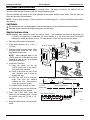
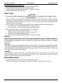
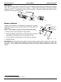
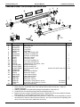
SERVICE MANUAL FREEDOM FREESTYLE RV 052573-301r2 12V MOTORIZED LATERAL ARM BOX AWNING W/ DIRECT RESPONSE Printed in USA September, 2013 TABLE OF CONTENTS Product Overview .......................................................................................................................... 2 Canopy Replacement .................................................................................................................... 3 Replacing the Lead Rail ................................................................................................................ 5 Installing the New Lead Rail. .................................................................................................................. 5 Arm Replacement .......................................................................................................................... 6 Replacing the Lead Rail Connector ........................................................................................................ 7 Pitch Adjustment ..................................................................................................................................... 7 Middle Arm Replacement 4.5 and 5 Meter Awnings............................................................................... 8 Motor Replacement ....................................................................................................................... 9 Remove Old Motor.................................................................................................................................. 9 Install the New Motor ............................................................................................................................ 10 Adjusting the Motor Limits .................................................................................................................... 11 Out Limit Switch ................................................................................................................................ 11 IN Limit Switch .................................................................................................................................. 11 Troubleshooting and Diagnostics ............................................................................................. 12 Common Operational Items .............................................................................................................. 12 Wiring ........................................................................................................................................... 14 Replacing the Direct Response Module ............................................................................................... 14 Optional LED Lighting................................................................................................................. 15 Switch Installation ................................................................................................................................. 15 Replacing the LED Strip ....................................................................................................................... 16 Harness Replacement .......................................................................................................................... 16 Standard Maintenance ................................................................................................................ 17 Fabric Care ........................................................................................................................................... 17 Mildew ............................................................................................................................................... 17 Pooling .............................................................................................................................................. 17 Leaking.............................................................................................................................................. 17 Motor Maintenance ............................................................................................................................... 17 Arm Noise ............................................................................................................................................. 18 Manual Override ................................................................................................................................... 18 Part Number Listing .................................................................................................................... 19 Freedom Freestyle Part Number Configuration .................................................................................... 19 Serial Number/Part Number Location ............................................................................................... 19 Freedom Freestyle Illustrated Parts List ............................................................................................... 20 Optional LED Lighting ........................................................................................................................... 21 PROPRIETARY STATEMENT The Freedom Freestyle Awning is a product of Carefree of Colorado, located in Broomfield, Colorado, USA. The information contained in or disclosed in this document is proprietary to Carefree of Colorado. Every effort is made to ensure that the information presented in this document is accurate and complete. However, Carefree of Colorado assumes no liability for errors or for any damages that result from the use of this document. The information contained in this manual pertains to the current configuration of the models listed on the title page. Earlier model configurations may differ from the information given. Carefree of Colorado reserves the right to cancel, change, alter or add any parts and assemblies, described in this manual, without prior notice. Carefree of Colorado agrees to allow the reproduction of this document for use with Carefree of Colorado products only. Any other reproduction or translation of this document in whole or part is strictly prohibited without prior written approval from Carefree of Colorado. SAFETY INFORMATION WARNING A WARNING INDICATES A POTENTIALLY HAZARDOUS SITUATION THAT, IF NOT AVOIDED, COULD RESULT IN DEATH OR SERIOUS INJURY AND/OR MAJOR PROPERTY DAMAGE. CAUTION A CAUTION INDICATES A POTENTIALLY HAZARDOUS SITUATION THAT MAY CAUSE MINOR TO MODERATE PERSONAL INJURY AND/OR PROPERTY DAMAGE. IT MAY ALSO BE USED TO ALERT AGAINST UNSAFE PRACTICES. NOTE: A note indicates further information about a product, part, or step. Tip: A tip provides helpful suggestions. Safety Notes: Always disconnect battery or power source before working on or around the electrical system. Always wear appropriate safety equipment (i.e. goggles). Always use appropriate lifting devices and/or helpers when lifting or holding heavy objects. When using fasteners, use care not to over tighten. Soft materials such as fiberglass and aluminum can be "stripped out" and lose the ability to grip and hold. Reference Publications located @ www.e-carefree.com: 052573-001 Freedom Freestyle Installation Manual 052573-201 Freedom Freestyle Owner's Manual 052573-301 Service Manual Carefree of Colorado 052573-301r2 2145 W. 6th Avenue Broomfield, CO 80020 Printed in USA a Scott Fetzer company September, 2013 FREEDOM FREESTYLE Service Manual Carefree of Colorado PRODUCT OVERVIEW Freedom Awnings are state of the art lateral arm awnings. When retracted, the housing provides protection against the elements while the streamlined styling blends in with the coach sidewall. The tensioned canopy fabric allows the awning to be extended partially or fully for best shade coverage. Each unit is equipped with lateral support arms. No vertical arms interfere with coach sidewalls, custom graphics or equipment that may be mounted on the sidewalls. Freedom Freestyle Specifications: Fully retractable and self-storing; Motorized; The sealed awning motor operates on standard 12VDC (range 10VDC to 14VDC); Case and frame are constructed of high-strength aluminum extrusions, protected with a polyester paint finish; Stainless steel fasteners and hardware. SPECIFICATIONS Awning Width 9.7cm [3.8”] 10.8cm 5.7cm Fabric Width [4.25”] [2.25”] 14.8cm [5.8”] wm001a Figure 1. General Dimensions. meters inches 4 4.5 157 177 250cm [98"] EXTENSION: LEAD RAIL SUPPORT: 4m or less: 2 Lateral Spring Arms; 4.5 & 5m 3 Lateral Spring Arms POSITION CONTROL: 12V Motorized w/ tubular motor 12V Direct Response - Standard MOTOR SPECIFICATIONS LENGTHS: Motor Type: Power: Torque Speed 3.0 118 3.5 168 Tubular 12VDC Minimum: 10VDC Nominal Current: 2.5Amps Continuous: 6Nm/4.5 ft-lbs. 24 rpm 5.0 197 Output: 30 Watts Max Current: 14Amps (stall @ min voltage) Tightening: 18Nm/13.2 ft-lbs. COLORS AVAILABLE Case Fabric:1 Satin, White or Black Vinyl Special Note: Dimensions are provided in centimeters. Conversion formulas are provided below. 2 Inches = Centimeters 2.54 Centimeters = Inches x 2.54 = Millimeters 25.4 Millimeters = Inches x 25.4 052573-301r2 Carefree of Colorado Service Manual FREEDOM FREESTYLE CANOPY REPLACEMENT This procedure requires two people. Spring Arms 1. Open the awning 18"-24". 2. Disconnect power to the awning. 3. Carefully push the lead rail toward the case so that the arms collapse and the fabric is slack. While holding the lead rail in this position, firmly tie the elbows of the spring arms together. Use a minimum 1/2" rope - do not use bungee cords. When tying the rope, use a non-slip knot such as a square knot or equivalent. CAUTION FAILURE TO SECURE THE LEAD RAIL AS DESCRIBED WILL ALLOW THE SPRING ARMS TO EXTEND OUT POSSIBLY CAUSING PERSONAL INJURY AND DAMAGE TO THE AWNING. Firmly Tie Elbows Together Marquee012 Figure 2. Tying the Arms. RH End Cap 15 in-lbs. Outer End Cap Inner End Cap RH End Plate Hem Rolls Against Roller Tube Fabric Retaining Screws 12-16 in-lbs. Pull and Hold Polycord While Placing Screw #10 x 2 Screw View of RH (Idler) Plug WM024a Figure 3. Fabric Replacement. 1. Remove the two (2) screws holding the outer end cap. Set the cap and screws aside. 2. On the motor side, remove the fabric retaining screw. It may be necessary to rotate the roller tube to align the screw with the access hole in the inner cap. 3. Remove the fabric retaining screw from the left lead rail end plate. 4. Remove the RH lead rail end plate and the RH end cap. 5. Slide the roller tube and fabric out of the case and lead rail. 6. Remove the fabric retaining screw located through the RH end plug. 7. Unroll the old fabric and slide off the roller tube. 8. Unfold the replacement fabric. CAUTION WHILE THE AWNING FABRIC IS FAIRLY ROBUST, CARE MUST BE TAKEN NOT TO SNAG IT WHILE SLIDING THE NEW FABRIC INTO THE ROLLER TUBE OR LEAD RAIL. Tip: Lightly spraying the slots with a dry silicone lubricant will help the fabric slide into the slot without staining the material. 052573-301r2 3 FREEDOM FREESTYLE Service Manual Carefree of Colorado 9. Slide the black polycord of the fabric into the fabric slot. Orient the fabric with the hem on the top (the hem will then roll against the roller tube). Center the fabric in the roller tube. 10. After the fabric is centered, on the RH end plug, pull and hold the excess polycord to one side of the fabric slot. Place one (1) #10 x 2 PHSD screw through the fabric slot hole and polycord. The screw must be positioned to thread into the metal of the roller tube slot and the edge of the polycord. The screw action will pull the polycord further into the slot hole. DO NOT OVERTIGHTEN, maximum torque 16 in-lbs. 11. After the screw is installed, trim the excess polycord. 12. Roll the fabric onto the roller tube. Note the direction of the wrap as shown. The view is of the RH plug. Allow adequate fabric to extend past the roller tube to cover the distance to the lead rail.. 13. Slide the fabric into the lead rail and the roller tube into the case. 14. Align the roller tube with the motor drive and bearing. Press the roller tube into the case. 15. Align the RH end cap with the roller tube and case and attach using the screws and spacer removed previously. Torque screws 15 in-lbs. 16. On the motor side, align the fabric slot of the roller tube and the access slot through the inner end cap. 17. Attach the fabric retaining screw through the motor bearing and into the roller tube. 18. Open and close the awning to confirm that the fabric rolls and unrolls squarely. Adjust the fabric position in the lead rail as required. 19. Center the fabric in the lead rail. Trim any excess polycord flush with the inside of the lead rail end plates. 20. Attach the RH end plate and the fabric retaining screws (both ends). NOTE: The top screw secures the fabric in the lead rail. The screw should be positioned to thread into the metal of the lead rail and the edge of the polycord. 21. Reattach the outer end cap on the LH side. Torque screws to 15 in-lbs. 22. After installing the canopy, it may be necessary to adjust the motor limits for motorized awnings. Refer to "Adjusting the Motor Limits" on page 11. 4 052573-301r2 Carefree of Colorado Service Manual FREEDOM FREESTYLE REPLACING THE LEAD RAIL This procedure requires a minimum of two people. This can be done while the awning is mounted on the vehicle. If being done before the awning is mounted, set the awning on a clean hard surface such as the floor of the shop. 1. Open the awning completely. There should be some slack in the fabric. If necessary, adjust the motor limits so that the motor can extend far enough to create slack in the fabric (refer to page 11). End Plate 2. 3. 4. 5. 6. 7. 8. 9. Measure Locations Ramp Arm Connector Measure Locations Center Ramp Arm Connector Ramp (centered in lead rail) Direct Response Module View of Back of Lead Rail Figure 4. Replacing the Lead Rail. End Plate FF014 Remove the LH and RH end plates and set aside. Carefully measure and record the locations of the ramps, arm connectors and Direct Response module. Loosen and slide out the outer ramps. Loosen the screws on the Direct Response module. Twist the brackets slightly and lift the sensor and brackets away from the lead rail. Disconnect the module from the wire harness. Quick connects are found behind the module. NOTE: It will be necessary to hold and support the lead rail during the removal and assembly. Loosen the arm connector screw for one arm and slide the arm and connector out of the lead rail. Allow the arm to extend fully and support the arm with a ladder or scaffolding. Repeat for the second arm. NOTE: If the unit has a center arm, loosen the screw. The arm connector is moved as the lead rail is slipped from the canopy. Loosen and slide out the center ramp. Slide the lead rail off the canopy fabric. If the unit has a center arm, slide the arm out of the lead rail while sliding the lead rail off the fabric. INSTALLING THE NEW LEAD RAIL. 1. Mark the new lead rail with the dimensions and locations measured previously. CAUTION WHILE THE AWNING FABRIC IS FAIRLY ROBUST, CARE MUST BE TAKEN NOT TO SNAG IT WHILE SLIDING THE NEW FABRIC INTO THE LEAD RAIL. Tip: Lightly spraying the slots with a dry silicone lubricant will help the fabric slide into the slot without staining the material. 2. Lift the lead rail up and slide onto the fabric. Center the fabric in the lead rail. If the unit has a center arm, begin sliding the arm into the lead rail at the same time. 3. Slide the center ramp into the lead rail. Do not tighten at this time. 4. Slide one arm connector into the lead rail. 5. Slide the other arm connector into the lead rail. 6. Align the arm connectors with the measurement marks made previously and tighten the screws. 7. Route the sensor cable behind the new connector. Reconnect the module to the wire harness. Position the module and brackets and tighten the screws. 8. Slide the outer ramps onto the lead rail and align with the measurement marks. Align the center ramp in the center of the lead rail. Tighten all screws to 25-30 in-lbs. 9. Attach the end plates. The top screws are the fabric retaining screws. NOTE: The top screw secures the fabric in the lead rail. The screw should be positioned to thread into the metal of the lead rail and the edge of the polycord. 10. After installing the lead rail, it may be necessary to adjust the motor limits for motorized awnings. Refer to "Adjusting the Motor Limits" on page 11. 052573-301r2 5 FREEDOM FREESTYLE Service Manual Carefree of Colorado ARM REPLACEMENT This procedure is for replacing the outside arms. For the middle arm on 4.5 and 5 meter awnings, refer to page 8. CAUTION THE SPRING ARM IS UNDER TENSION TO OPEN. USE EXTREME CARE AND FIRMLY HOLD THE SPRING ARMS DURING ASSEMBLY AND DISASSEMBLY TO AVOID ANY SUDDEN OR UNEXPECTED MOVEMENT BY THE ARM. SERIOUS PERSONAL INJURY AND/OR PROPERTY DAMAGE COULD OCCUR. 1. Open the awning to the maximum extension or as wide as possible. Adjust the motor limits (see page 11) to allow the lead rail to over extend and create slack in the fabric. This is to minimize the spring tension in the arms during this procedure. Pin 2. Disconnect power to the awning. Lead Rail Connector 3. Use a scaffold, ladder or other means to support the lead rail. 4. If replacing the LH (motor side) arm, carefully remove the sensor cable from the wire channel on top of the arm. Use care to not bend, break or compromise the cable. Arm 5. At the lead rail, firmly hold the spring arm and remove the clip and pin that secures the arm to the lead rail connector. Set parts aside to be reused. Clip WM036 6. Allow the arm to extend below the lead rail. Support the end of the arm. 7. Loosen the pitch adjustment screws. 8. Remove the retaining clip from the case connector. Remove the arm from the awning. Retaining Clip Pitch Adjustment Screws Set Screw Pin Pivot Assy Bottom Hole of Case Connector FF013 If replacing the lead rail connector, go to page 7 then return here. 9. Remove the pivot assembly from the arm by removing the set screw and pin. 10. If the arm has wire channel mounted for the sensor cable, carefully remove the channel from the arm to reuse on the new arm. 11. Install the pivot assembly on the new arm using the pin and set screw removed previously. Torque set screw to 15-20 in-lbs. 12. Using two people firmly hold the new arm assembly and remove the shipping ties. Allow the arm to open slowly to its maximum extension. CAUTION When the arm is closed, it can open with significant force. opening the arm. Use care when Tip: Use a floor or ground cover and place one knuckle and arm half on the ground. Have one person firmly hold the arm half on the ground while the second person carefully opens the other arm half. 13. If the sensor cable is routed on the replacement arm: a. Attach a piece of wire channel to the top of each section of the arm using double sided tape. If using new channel, cut each piece slightly shorter than the arm extrusion. 14. Lift the arm assembly into position and slide the pivot into the lower hole of the case connector. 6 052573-301r2 Carefree of Colorado Service Manual FREEDOM FREESTYLE 15. Secure the pivot assembly to the case connector with the retaining clip. 16. Slide the arm onto the lead rail connector and secure using the pin and clip removed previously. 17. For the LH arm, route the cable through the wire channel. At the arm joints, arch the cable slightly to avoid binding. Do not twist the cable. Tip: Use a small tool, such as a flat bladed screwdriver to gently spread open the channel then insert the cable. Do this for the entire length of the channel until the cable is fully inserted. 18. Remove the supports from the lead rail. 19. After replacing the arm, it will be necessary to adjust the pitch to align the lead rail and case. See page 7. 20. Adjust the motor limits as required. See page 11. REPLACING THE LEAD RAIL CONNECTOR 1. Remove the arm according to the instructions on page 6. 2. Remove the lead rail end plate. 3. Carefully measure and mark the location of the existing connector and ramp and sensor (when installed). Arm Connector 4. Loosen the securing screw and slide the existing ramp from the lead rail. Remove Ramp End Plate Direct Response Module FF015 5. Loosen the screws on the sensor. Twist the brackets slightly and lift the sensor and brackets away from the lead rail. Disconnect the module from the wire harness. Quick connects are found behind the module. 6. Loosen the securing screw and slide the existing connector from the lead rail. 7. Insert the new connector assembly into the lead rail and position at the marks made previously. CAUTION Failure to position the connector correctly will cause the arm and lead rail not to close correctly. 8. Tighten the outer securing screw. 9. For the sensor cable. Route the cable behind the new connector. Reconnect the module to the wire harness. Position the module and brackets and tighten the screws. 10. Install the ramp. 11. Attach the lead rail end plate. 12. Return to Replacing the Arm on page 6. PITCH ADJUSTMENT The pitch for Freedom Freestyle can be adjusted to Loosen Top Screw when Adjusting optimize the installation. Tighten When Finished 1. Open the awning to access the adjustment screws located on the arm case knuckles. Lower Raise 2. Have a second person lift up on the lead rail to relieve the pressure on the adjustment screws. 3. Using a 4mm allen wrench, loosen the top screw. Turn Arm Case Knuckle Pitch Adjustment Screw FF003 the bottom adjustment screw clockwise to raise the lead rail; turn the adjustment screw counterclockwise to Figure 5. Pitch Adjustment. lower the lead rail. 4. When the pitch is set at the desired angle, tighten the top screw. 5. Repeat for each arm. Ensure that the lead rail is parallel with the awning case. Special Note: The Freedom Freestyle lead rail self-adjusts to accommodate the pitch. No adjustment is required to the lead rail when the pitch is adjusted. 052573-301r2 7 FREEDOM FREESTYLE Service Manual Carefree of Colorado MIDDLE ARM REPLACEMENT 4.5 AND 5 METER AWNINGS CAUTION THE SPRING ARM IS UNDER TENSION TO OPEN. USE EXTREME CARE AND FIRMLY HOLD THE SPRING ARMS DURING ASSEMBLY AND DISASSEMBLY TO AVOID ANY SUDDEN OR UNEXPECTED MOVEMENT BY THE ARM. SERIOUS PERSONAL INJURY AND/OR PROPERTY DAMAGE COULD OCCUR. CAUTION THE MIDDLE SPRING ARM IS DIFFERENT THAN THE OUTER ARMS. CENTER ARMS CAN BE IDENTIFIED BY THE BLUE DOT LOCATED ON OR NEAR THE CASE CONNECTOR OF THE ARM. DO NOT USE CENTER ARMS FOR REPLACING OUTER ARMS, DO NOT USE OUTER ARMS TO REPLACE THE CENTER ARM. Tools Required: Flat blade screwdriver (1/4"), needle nose pliers, regular pliers and/or e-ring tool. New e-clips are included with the replacement arm. Special Note: Carry the necessary tools, ties or sleeves and new e-clips. These must readily available during the procedure. Pin 21. Open the awning 2 to 3 feet. Lead Rail Connector 22. Disconnect power to the awning. 23. At the lead rail, firmly hold the spring arm and remove the clip and pin that secures the arm to the lead rail connector. Set pin aside to be reused. Arm 24. Fold the arm and secure using a large zip tie or cord. Do not use bungee cords. Clip 25. Loosen the pitch adjustment set screws. WM036 26. Remove the retaining clip from the case connector. Pitch Adjustment Screws Retaining Clip Bottom Hole of Case Connector FF013a 27. Remove the arm from the awning and set aside. CAUTION When the arm is closed, it can open with significant force. Use care when opening the arm. 28. Lift the arm assembly into position and slide the pivot assembly into the case connector. NOTE: the pivot goes into the lower hole of the connector. 29. Secure the pivot assembly to the case connector with a new retaining clip (large). 30. Firmly hold the new arm assembly and remove the shipping ties. Allow the arm to open slowly. 31. Slide the arm onto the lead rail connector and secure using the pin removed previously and a new clip (small). NOTE: When aligning the pin through the arm and lead rail connector, it may be necessary to pivot the lead rail. The lead rail is made to pivot on the lead rail connectors. 32. Tighten the lower pitch adjustment screw until snug. 33. Tighten the upper pitch adjustment screw. 8 052573-301r2 Carefree of Colorado Service Manual FREEDOM FREESTYLE MOTOR REPLACEMENT Spring Arms 1. Disconnect power to the awning. 2. If the awning is extended: Carefully push the lead rail toward the case so that the arms collapse. While holding the lead rail in this position, firmly tie the elbows of the spring arms together. Use a minimum 1/2" rope - do not use bungee cords. When tying the rope, use a non-slip knot such as a square knot or equivalent. 3. If the awning is closed: Firmly brace the lead rail in the closed position. A second person can hold the lead rail steady during the disassembly process. Firmly Tie Elbows Together Marquee012 CAUTION FAILURE TO SECURE THE LEAD RAIL AS DESCRIBED WILL ALLOW THE SPRING ARMS TO EXTEND OUT SUDDENLY POSSIBLY CAUSING PERSONAL INJURY AND DAMAGE TO THE AWNING. REMOVE OLD MOTOR Remove Wire From End Cap Motor Screws Outer End Cap Inner End Cap Motor Retaining Screw Fabric Slot FF016 1. Remove the two (2) screws holding the outer end cap. Set the cap and screws aside. 2. Disconnect the motor wire quick disconnects located under the outer cap. 3. Remove the three (3) screws and spacer holding the inner end cap to the case. Remove the two (2) motor screws. CAUTION IF THE AWNING IS CLOSED WHEN THE INNER END CAP IS DETACHED, THE SPRING ARMS WILL TRY TO OPEN. CONTINUE TO HOLD THE LEAD RAIL CLOSED. 4. Carefully pull the inner end cap away from the case and remove the wires from the end cap. aside. Set the end cap 5. Remove the fabric retaining screw then pull the motor out of the roller tube and set aside. CAUTION IF THE AWNING IS CLOSED WHEN THE MOTOR IS REMOVED, THE SPRING ARMS WILL TRY TO OPEN. SUPPORT THE ROLLER TUBE AND ALLOW THE AWNING TO OPEN SLOWLY THEN SECURE THE ARMS BY TYING THE ELBOWS TOGETHER AS DESCRIBED PREVIOUSLY. 052573-301r2 9 FREEDOM FREESTYLE Service Manual Carefree of Colorado INSTALL THE NEW MOTOR Route Wire From Harness Thru Hole in End Cap #10 x 2 Retaining Screw 12-16 in-lbs. Route Motor Wire Thru Hole in End Cap “B” Bearing M4 x 25mm Screw (x3) 25-30 in-lbs. One-Way Drive Connect Motor Wires with Harness Wires Outer End Cap Spacer (x1) Plug FF017 1. Check that the one-way drive is installed on the new motor assembly with the "B" pointing toward the motor. WARNING THE ONE-WAY DRIVE MUST BE ORIENTED WITH THE "B" FACING THE MOTOR. IF THE DRIVE IS NOT ORIENTED CORRECTLY, THE AWNING NOT TO OPERATE AND THE ARMS WILL SPRING OUT WHEN RELEASED. 2. Route the new motor wire through the hole in the end cap. 3. Align the one-way drive with the roller tube and start sliding the new motor into the roller tube. 4. Route the wire from the harness through the hole in the end cap. 5. Align the bearing on the motor and slide into the roller tube. 6. Through the access hole in the inner end cap, attach the fabric retaining screw through the bearing and in the fabric slot. The screw must be positioned to thread into the metal of the roller tube slot and the edge of the polycord. It may be necessary to rotate the roller tube to align the access hole and fabric slot. 7. Align the screw holes in the inner end cap and attach to the awning case using three (3) M4 x 25 screws and 1 spacer in the front attach hole. 8. If not previously done, terminate the wires from the motor with .187 male disconnects to match the harness wire. Attach the motor and harness wires, matching the wire colors (Blue to Blue and Brown to Brown). Fold and tuck the wires and connectors to fit inside the outer end cap. 9. While holding the lead rail, carefully remove any roller tube supports and arm ties. Allow the lead rail to extend until the fabric is taut. If the lead rail continues to extend after the fabric is taut, the one way drive was installed backwards. Retie the arms, remove the motor and orient the one way drive as shown. 10. To test, restore power then extend and retract the awning. 11. After replacing the motor, it will be necessary to adjust the motor limits (page 11). 12. After testing and adjusting the motor limits, attach the outer end cap. 10 052573-301r2 Carefree of Colorado Service Manual FREEDOM FREESTYLE ADJUSTING THE MOTOR LIMITS “OUT” 4mm Hex “IN” Endcap Plug 4mm Hex WM011a Out Limit Switch The “OUT” limit switch stops the motor when the awning is fully extended 1. Extend the awning out completely. 2. Confirm that the arms are fully extended. The motor should stop and the fabric should be tight. If the motor continues to run, the fabric will sag; or, if the motor quits before the arms are fully extended, it will be necessary to adjust the “OUT” limit switch. 3. Using a 4mm Allen wrench turn the “OUT” limit switch. CLOCKWISE increases time the motor runs during extension, COUNTERCLOCKWISE reduces the time the motor runs. NOTE: It is best to make the adjustments in increments of a single turn. 3 full turns of the screw equals approximately 2” of fabric extension. 4. Extend and retract the awning several times to confirm that the adjustment is correct. 5. Repeat steps 3 and 4 as required until the awning extends correctly. IN Limit Switch NOTE: The "IN" limit switch is not adjusted when the Direct Response system is installed. The system electronics monitors the motor and shuts the motor off when the awning is fully retracted. If the "IN" limit switch is accidently adjusted, the motor may shut off before the awning is fully closed. If this occurs, turn the "IN" adjustment screw clockwise. It is not necessary that the screw position matches the closed position. The Direct Response electronics controls the closed position. 052573-301r2 11 FREEDOM FREESTYLE Service Manual Carefree of Colorado TROUBLESHOOTING AND DIAGNOSTICS The following procedures are intended to aid the service technician to resolve operational issues with the electronics installation. Common Operational Items The following are operational items that may come up as questions during normal operation. 1. The awning seems to extend and retract slowly. The operational range is 20-25 seconds to extend or 25-35 seconds to retract. If the power supply is on the low side of the range (10V) the awning will move slower. 2. After a period of use, the arm knuckle joints may slide together slightly making a squeaking or squealing noise; this is normal and not a reason for concern. Refer to page 18. In the charts below, YES is a positive response to the test; NO is a negative response. D01 A B C THE AWNING DOES NOT EXTEND AND/OR RETRACT Check Installation Integrity Use the wiring diagram and confirm that the components and wiring are properly installed and connected Confirm Power Supply Is vehicle battery or power source providing 10V to 14V to the Switch? NOTE: The battery may have a "surface charge" when not in use. This will give a false value if testing. Test the battery under load to receive a valid value. Test Motor Function 1. Remove the outer end cap on the motor side. 2. Disconnect the motor wires from the harness. 3. Connect the motor wires to a 12-14VDC power source (i.e. drill battery). If the awning does not move, reverse the leads on the battery and try again. CAUTION Be sure to attach the D E 12 leads to the battery. Connecting the harness wires to the power source will seriously damage the Direct Response module. 4. Does the motor run? Test wire continuity in the harness 1. There are two wires from the module to the motor connection. 2. There are four wires from the module to the switches. 3. There is one wire to chassis ground. 4. Confirm the wires are isolated and not shorted against the vehicle or each other Test Switch Function 1. Test Power Switch 1.1. Disconnect wires from Power Switch. 1.2. Using a continuity tester place one lead on each terminal. 1.3. With the switch in the OFF position, circuit should be open. 1.4. With the switch in the ON position, circuit should be closed. 2. Test the Extend/Retract Switch 2.1. Using a continuity tester, place one lead on center pin. Place the second lead on bottom pin. Put the switch in the center position and measure the continuity. Circuit should be open. 2.2. Press the switch down (Extend). Circuit should be open. 2.3. Press the switch up (Retract). Circuit should be closed. 2.4. Move the second lead to the top pin. Put the switch in the center position and measure. Circuit should be open. 2.5. Press the switch down (Extend). Circuit should be closed. 2.6. Press the switch up (Retract). Circuit should be open YES NO Go to test B Correct as required YES NO Go to test C Correct as required YES NO Motor is good, go to test D Motor is defective - replace YES Wire continuity good – reconnect the wires disconnected in the previous test then go to test E Repair as required then reconnect the wires MOTOR NO YES NO Switches are good. Module is defective - replace Switches are defective - replace 052573-301r2 Carefree of Colorado D02 Service Manual FREEDOM FREESTYLE LEAD RAIL DOES NOT CLOSE CORRECTLY A Does lead rail close parallel to the case? YES NO Go to test B Correct the pitch setting so arms are even. Refer to page 7. B Does lead rail stop before reaching case? 1. Is the fabric rolling onto the roller tube correctly? The fabric must roll onto the roller tube from the bottom. YES NO 2. Is the motor stopping before the awning is closed? YES Go to test B2 Using the close position of the switch, overextend the awning until the fabric rolls under the roller tube. Check the motor "out" limit switch (page 11) so that the motor stops when the fabric is extended and still wrapped beneath the roller tube If the "in" motor limit switch is not correct, the lead rail can stop before reaching the case. Refer to page 11 Go to test C NO C Is the arm lead rail connector in the wrong position 1. Do the arm elbows strike the case before the awning is closed? 2. Do the arm elbows strike the lead rail before the awning is closed? Connectors Too Far From Lead Rail End Connectors Too Close To Lead Rail End Arm Connector 052573-301r2 YES YES The lead rail connectors are set to far from the end of the lead rail. Loosen the screw and slide the connector toward the end of the lead rail. Make sure both sides are even. Make adjustments in small increments and retest. The lead rail connectors are set to close to the end of the lead rail. Loosen the screw and slide the connector away from the end of the lead rail. Make sure both sides are even. Make adjustments in small increments and retest. Connectors Correct Arms Close Evenly FF019 13 FREEDOM FREESTYLE Service Manual Carefree of Colorado WIRING Awning To +12VDC .187, 14-16awg Female Spade Terminals (qty: 2) Rear View of Switch Assy Extend/Retract F F M M Brown Blue On/Off .187, 18-20awg Female Spade Terminals (qty: 3) F M F Red Black Red F M F M F M F M F M Black Brown Yellow Brown Yellow Gray Gray Additional Extend/Retract Switch M .25, 14-16awg Spade Terminals 1 Male, 1 Female Control Module (mounted in lead rail) M F Chassis Ground FF001 REPLACING THE DIRECT RESPONSE MODULE The Direct Response Module is located on the LH side (motor side) of the lead rail. NOTE: The Freestyle awning will not operate electrically when the module is disconnected. To Remove: 1. Disconnect power to the awning. Quick Disconnects 2. Remove the two screws holding the module. Pull the module from the lead rail. NOTE: The mounting brackets are held in place by tension from the screws. When the screws are removed, the brackets will sit loosely in the lead rail. Use care save the brackets. 3. Detach the quick release connectors. Direct Response Module FF018 4. Set the module aside. To Install: 1. Connect the wires. Make sure to match wire color and size when making connections. 2. Position the brackets. 3. Tuck the wires and connectors behind the module and attach the module with the two screws removed previously. 14 052573-301r2 Carefree of Colorado Service Manual FREEDOM FREESTYLE OPTIONAL LED LIGHTING An LED light strip is available as a factory installed option The strip is mounted in the lead rail with the harness routed through the awning with the Direct Response cable. Route the twisted wire cable for the LED lighting into the vehicle with the motor cable. Seal the hole and wires with a quality silicone sealant. NOTE: There is approximately 13 feet of wire from the wall entry point. Controls should be located within this distance. CAUTIONS: Do not route the wire over sharp edges or heat sources that can cut or fray the wires or wire insulation. Damage that is a result of improper routing may void warranty. SWITCH INSTALLATION NOTE: Installers may choose to furnish the control switch. The installation requires that the power line (+12VDC) be attached to a dedicated 2A circuit breaker or a 2A in-line fuse must be installed between the switch and power source. For easy access, locate the fuse close to the switch. 1. Determine the location of the switch. 3. Wire the switch as shown below. Wire terminals at the switch are .187, 18-24 awg female disconnects. NOTE: Allow adequate slack in the 12VDC power line so that the in-line fuse (installed in step 4) can be accessed from behind the switch. 4. Install the in-line fuse: 4.1. Near the switch, cut the red 12VDC power line to the switch. Do not strip the insulation. 4.2. Insert a wire end into one of the wire channels until it butts up against the stop. 4.3. Fold that half of the connector body over until the element contacts the wire. Use pliers to crimp the connector closed. 4.4. Repeat for the second wire end. 4.5. Slide the fuse into the fuse port. Ensure that is firmly seated. 5. Press the in-line fuse, wires and switch into the mounting hole. Secure the switch using two (2) #6 x 1/2" screws. 1.13" 2A In-line Fuse (+12VDC Line) #6 x 1/2” Screw (x2) ON 1.5" 2.9" OFF 1.88" +12VDC 2A In-line Fuse 18-24awg Female Disconnect (x2) Red 18awg Wire (minimum) Single Pole Single Throw Switch GND Vehicle Wall Red Black 2. At the switch location, cut a 1 1/8" x 1 1/2" hole. LED Strip in Lead Rail Connector at Lead Rail Wire Routed in Arm LED002c 6. Snap the switch bezel over the switch frame. 052573-301r2 15 FREEDOM FREESTYLE Service Manual Carefree of Colorado REPLACING THE LED STRIP Wire Channel Tie Strap Harness Connector Cut Between Pads to Adjust Length LED Strip LED Slot FF020 1. 2. 3. 4. 5. 6. 7. 8. 9. Extend the awning out completely. Disconnect power to the awning and the LED strip. Use a non-permanent marker to mark the location of the ends of the LED strip. Inside the lead rail, disconnect the strip connectors. Remove the existing LED strip from the lead rail. Clean the slot to remove any dirt and tape residue. Thread the new strip behind the lead rail connectors. Starting at the reference mark on the harness end, press the new strip into the LED slot. At the end of the lead rail, cut the LED strip to match the mark made previously. To trim the LED strip, always cut between the 4-pad cluster as shown. 10. Route the new LED strip wires as shown and connect to the harness. 11. Restore power and test. HARNESS REPLACEMENT 1. Extend the awning out completely. 2. Separate the LED connectors at the lead rail. Carefully pull the harness from the wire channel at the top of the arm. 3. At the awning case: 3.1. The wire is routed with the motor wire. To access the wire, it will be necessary to remove the outer end cap from the motor side. 3.2. Clip the harness then clamp the harness to prevent it from falling in the vehicle wall. 4. Connect the new harness to the LED strip. 5. Route the harness through the wire channel. At the arm joints, arch the cable slightly to avoid binding. Tip: Use a small tool, such as a flat bladed screwdriver, to gently spread open the channel then insert the cable into the channel. Do this for the entire length of the channel until the cable is fully inserted. 6. At the vehicle wall: 6.1. Route the new harness through the wall to the switch or dimmer module. Tip: Tie the new harness to the old harness that was cut previously. Use the old harness to pull the new harness through the wall to the desired location. 6.2. Seal the wall entrance hole and harness with a quality silicone sealant. 6.3. Connect the new harness to the switch. Two (2) .187, 18-24 awg female disconnects are provided if connecting to a switch. 6.4. Alternate method: At the wall, splice the new harness to the existing harness using 24 awg butt connectors. Push the connectors into the vehicle wall. Seal the wall entrance hole and wires with a quality silicone sealant. NOTE: Be sure to allow enough harness from the arm to provide a slack in the harness and adequate length for the connectors to be pushed inside the wall before sealing the hole and harness with a quality silicone sealant. 16 052573-301r2 Carefree of Colorado Service Manual FREEDOM FREESTYLE STANDARD MAINTENANCE Maintaining a Carefree Awning is easy. Just follow these basic steps: Always operate the awning according to the instructions. Periodically check that the fasteners are tight. Tighten if necessary. Keep the awning fabric and arms clean. FABRIC CARE CAUTION DO NOT USE OIL BASED CLEANERS OR ANY CAUSTIC, GRANULATED, OR ABRASIVE TYPE CLEANERS ON YOUR CAREFREE PRODUCT. 1. One of the best ways to keep the fabric looking good and to delay the need for deep or vigorous cleanings is to hose fabrics off on a monthly basis with clear water. This practice will help prevent dirt from becoming deeply imbedded in the fabric. In most environments, a thorough cleaning will be needed every two to three years. 2. When it is time for a thorough cleaning, the fabric can be cleaned while still on the awning frame. For Vinyl Fabric – Use a soft brush and warm water with soap. For Acrylic Fabric – Use a stiff brush and warm water with soap. 3. When cleaning the fabric, it is important to observe the following: Always use a natural soap, never detergent. Water should be cold to lukewarm, never more than 100F. Air-dry only. Never apply heat to the fabric. Always allow the fabric to dry thoroughly before rolling up the awning. Mildew Mildew is a fungus growth that looks like dirt. Vinyl coated polyester fabrics are mildew resistant because of a chemical biocide in the vinyl coating. Under ordinary conditions, mildew will not appear. However, in areas where high temperature and humidity are common, mildew can be a problem and require the material to be washed more frequently. Pooling When water collects on the top of the fabric, this is known as "pooling". This can occur during inclement weather or if a running air conditioner discharges over the awning. The water is dumped when the awning is retracted. It is recommended that if water accumulates; retract the awning in steps (8"-12") to dump the water. This will help prevent the fabric from stretching or distorting. Leaking On vinyl canopies, side hems and poly cords are stitched in with a sewing machine. On occasion, this stitching may allow water to seep or leak through the stitches. This is normal and not a defect covered by warranty. Treat the seams with a quality seam sealer. MOTOR MAINTENANCE Check all wiring and connections for wear. Repair when needed. Check that the sealant is providing a good seal and no water is accumulating on the wiring. 052573-301r2 17 FREEDOM FREESTYLE Service Manual Carefree of Colorado ARM NOISE After a period of use, the arm knuckle joints may slide together slightly making a squeaking or squealing noise; this is normal and not a reason for concern. To reduce the sound, apply a few drops of multipurpose oil (3-IN-1® 1 or equivalent) on the knuckle joint seams. Operate the awning and repeat 3-4 times to allow the oil to penetrate into the joint. Apply Light Oil in Joint Seams Case Center Knuckle Lead Rail WM017 MANUAL OVERRIDE If power to the vehicle is not available, the awning can be safely retracted using the manual override located on the idler (right) end of the case. NOTE: This procedure cannot be used to extend the awning. Remove Plug 3/8” Square Key or 3/8” Socket Drive Extension 1. Remove the plug from the right end cap and save. 2. Insert the optional override key or a 3/8" socket drive extension and handle into the square drive hole inside the end cap. 3. Turn the handle counterclockwise until the awning is retracted. 4. Replace the plug. WM012 CAUTION After closing the awning with the manual override, the lead rail may move out from the case 1/4" -1/2". This is normal and the awning is secure for travel until power is restored or repairs are completed. Do not attempt to force the lead rail in with the override, serious damage can occur to the awning. 1 ® 3-IN-1 is a registered trademark of the WD-40 company. 18 052573-301r2 Carefree of Colorado Service Manual FREEDOM FREESTYLE PART NUMBER LISTING FREEDOM FREESTYLE PART NUMBER CONFIGURATION Example Part Number: CA13858JVTM CA Freedom WM Patio Awning SERIES CODE CA = Freedom Freestyle Patio Awning 138 138" [3.5 m] SIZE 118” [3 m] 138” [3.5 m] 157” [4 m] 177” [4.5 m] 58 Black/Gray JV Black CANOPY COLOR CASE COLOR AVAILABLE FABRICS: STANDARD VINYL (COLOR KEY 1) 25 = WHITE ACRYLIC (COLOR KEY 2) CUSTOM ACRYLIC (SEE NOTES) TM TM MOTORIZED TM = Motorized JV = BLACK 23 = SATIN FOR COLORS, REFER TO THE COLOR CHART AVAILABLE ON-LINE AT www.carefreeofcolorado.com or www.e-carefree.com. 197” [5 m] Serial Number/Part Number Location Serial# / Part# Located on the Inside of the Left End of Case FF009 052573-301r2 19 FREEDOM FREESTYLE Service Manual Carefree of Colorado FREEDOM FREESTYLE ILLUSTRATED PARTS LIST 5 4 3 19 9 1 2 12 9 4 8 14 13 8 8 10 16 11 7 15 18 ON RETRAC T 17 6 21 OFF Awning EXTEND Control FF501 Item 1 2 3 4 Part Number Description Notes R001618XXX Endcap, LH, Outer 1 R001712XXX Motor Assy, LH 1,2 R001620XXX Endcap, RH 1 R040792-005 Plug, White R040792-006 Plug, Black R001623 Roller Tube Endplug, RH 5 R001624XXX End Plate, Lead Rail, LH 1 6 R001625XXX End Plate, Lead Rail, RH 1 7 R001621 Ramp Kit, Leadrail 8 R001677 Pivot Assy, Case 3 9 R001678 Pivot Assy, Lead Rail, LH 3 10 R001680 Pivot Assy, Lead Rail, RH 3 11 R001630 Hardware Pack, Arm Attach, 1 Arm 12 R012530-TB94L Spring Arm Assy, LH 3 13 R012530-TB94R Spring Arm Assy, RH 3 14 R012530-TB94M Spring Arm Assy, Center Used on 4.5 and 5 meter only 3,4,6 R019468-006 Switch Kit 15 R060686-002 Sensor/Control Module 16 R001679 Bracket Kit, Sensor 17 R040616-006 Cable Channel, Black 18 R040616-005 Cable Channel, White 019867-001 Bracket Kit, 3m-4m 5 19 019867-002 Bracket Kit, 4.5m-5m 5 019868-001 Screw Pack, Awning Mount, 3m-4m Not Shown 20 019868-002 Screw Pack, Awning Mount, 4.5m-5m Not Shown 901075 Manual Override Key 21 NOTES 1. XXX = Color; WHT = White; BLK = Black; GRY = Satin 2. Motor Assy (item 2) includes motor, inner endcap, bearing and one-way drive. Parts not available separately. 3. Attaching hardware not included with spring arm assemblies. Order item 12. 4. Center arm for 4.5m and 5m awnings uses pivot assembly (item 11). 5. Bracket kit 3m-4m contains 3 brackets and screws. Bracket Kit for 4.5m-5m contains 4 brackets. Bracket kits do not include awning mounting screws; order item 20. 6. The middle spring arm is different than the outer arms. Center arms can be identified by the blue dot located on or near the case connector of the arm. Do not use center arms for replacing outer arms, do not use outer arms to replace the center arm. 20 052573-301r2 Carefree of Colorado Service Manual FREEDOM FREESTYLE OPTIONAL LED LIGHTING 3 2 5 ON OFF 1 4 Item 1 2 3 4 5 Notes: Part Number Description LED Strip R001729 Harness R040616-206 Wire Channel SR0101 Switch Kit (includes item 5) 019493-001 Fuse Kit (includes in-line fuse holder and 2A fuse) 1. LED strip (item 1) is sent on a roll and cut to length during installation. 052573-301r2 FF020 Notes 1 21 FREEDOM FREESTYLE Service Manual Carefree of Colorado NOTES: 22 052573-301r2