1
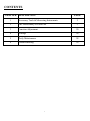
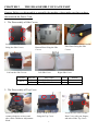
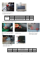
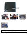
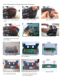
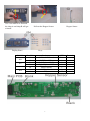
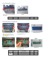
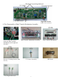
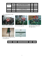
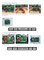
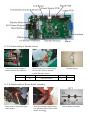
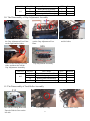
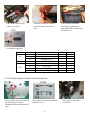
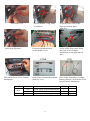
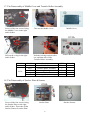
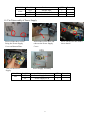
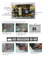
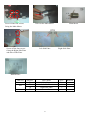
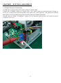
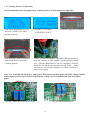
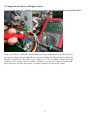
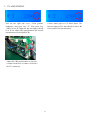
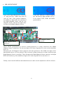
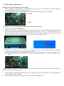
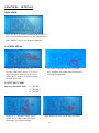
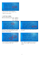
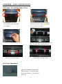
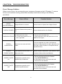
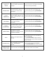
SERVICE MANUAL
For D-100 USD
October-10 Edition
CONTENTS
CHAPTER DESCRIPTION
PAGE
1
Necessary Tools & Measuring Instruments
2
2
The Disassembly of Each Part
3
3
Function Adjustment
20
4
Settings
26
5
Daily Maintenance
28
6
Troubleshooting
29
1
CHAPTER 1
NECESSARY TOOLS & MEASURING INSTRUMENTS
1. 2.5” Screwdriver
2. 2.5 Cross-point Screwdriver
3. 65 mm insulated instrument Screwdriver
4. Inner Allen Key
5. Nylon-faced Hammer
6. Insulated tweezers
7. Ring Spanner
8. Multi-meter
9. Sleeve Barrel
10. Needle File Set
11. Miniature Soldering Iron
12. Narrow Nose Pliers
2
CHAPTER 2
THE DISASSEMBLY OF EACH PART
Caution: Before you disassemble or assemble the machine, please make sure that you have
disconnected the Power Cord.
1. The Disassembly of Side Covers
Screw off the two screws on the
Bottom Plate fixing the Side
Covers.
Screw off the four screws
fixing the Side Covers.
Pull out the Side Covers.
Unit NO.
001A
Left Side Cover
Part NO.
1A
2A
Part’s name
Left Side Cover
Right Side Cover
Screw off the two screws on the
Side Plates fixing the Side
Covers.
Right Side Cover
QTY.
1
1
Remark
2. The Disassembly of Top Cover
Screw the inside screw
counter-clockwise to loose and
take off the Thickness Adjustment
Knob.
Screw off the two screws
fixing the Top Cover.
3
Loose the two screws on the
Rear Cover with your fingers,
and take off the Top Cover.
Top Cover Assembly
Screw off the two screws fixing
the Top Cover Fixer Shaft on
the right and left sides.
Unit NO.
002
Part NO.
4
5
6
Part’s name
Thickness Adjustment Knob
Top Cover
Top Cover Fixer Shaft
QTY.
1
1
1
Remark
3. The Disassembly of Rear Cover
Screw off two screws fixing the
Rear Cover on the right and left
sides.
Disconnect the connector on
the Rear Cover.
Take out the Power Supply
Cover a little so as to pull
off the Power Wire.
Rear Cover Assembly
Unit NO.
Part NO.
3-1
3-2
Part’s name
Rear Cover
Power Wire
4
Screw off the three screws
fixing the Power Supply
Cover on Bottom Plate.
QTY.
1
1
Remark
+
4. The Disassembly of Notes Guider Assembly
Screw off the four screws fixing
the Note Guide Plate on the left
and right sides.
Pull upwards to take off the
Note Guider Assembly.
Note Guider Assembly
(Front Picture)
Note Guider Assembly
(Back Picture)
Unit NO.
003
Part NO.
7
8
9
Part’s name
Note Entry Cover
Note Guider part
Middle Note Guide Plate
QTY.
1
2
1
5
Remark
5. The Disassembly of Display Panel and LCD Board
Pull out the C-Ring fixing the
Gear.
Screw off the four screws fixing
the Display Panel on the right
and left sides.
Display Panel Assembly
Screw off the four screws fixing
the two Keyboard PCBs.
Take off the Timing Belt.
Disconnect the 16 PIN Connector.
Screw off the four screws fixing
the LCD Board.
Use a sleeve barrel to screw
off the four screws fixing the
two Keyboard PCBs.
6
Take off the Gear.
Take off the Display Panel.
LCD & LCD Board
Keyboard PCB
Use a screwdriver to unclench
the clasp A and clasp B will get
released.
Display Panel
Unit NO.
006
007
004
Pull out the Hopper Sensor.
Hopper Sensor
Keys
Part NO.
18
19
20
21
54
10
11
Part’s name
LCD & LCD Board
LCD Board Wire
Left Keyboard PCB
Right Keyboard PCB
Hopper Sensor
Display Panel
Keys
7
QTY.
1
1
1
1
1
1
23
Remark
6. The Disassembly of Stacker
Screw off the two screws fixing
the Stacker.
Unit NO.
Part NO.
12
Stacker
Part’s name
Stacker
QTY.
1
Remark
7. The Disassembly of Signal PCB
Press two tabs on the left and
right as shown by the arrow
sign ( ), and the Cover will
pop up a little.
Screw off the four screws fixing
the Signal PCB Cover.
Screw off the two screws fixing
the Signal PCB.
Disconnect all the connectors
on the Signal PCB.
Unit NO.
008
Part NO.
13
22
23
Part’s name
Signal PCB Cover
Signal PCB Wire
Signal PCB
8
Signal PCB Cover
Signal PCB
QTY.
1
1
1
Remark
Left MR Sensor
Right MR Sensor
8. The Disassembly of Back Transfer Mechanism Assembly
Screw off the two screws
fixing the Back Transfer
Mechanism on the right and
left sides.
Receiver Counting Sensors (Part
No. 55)
Back Transfer Mechanism Assembly
UV Sensor Assembly
Left /Right MR Sensor
9
Back Transfer Mechanism
MR Sensor
Unit NO.
014A
016
Part NO.
48A
49
50
55
57A
58A
58C
Part’s name
Back Transfer Mechanism
Upper Press Roller
Transfer Mechanism Shaft
Receiver Counting Sensors
UV Sensor Assembly
MR Sensor
Left /Right MR Sensor
QTY.
1
2
1
1
1
1
2
Remark
A pair
9. The Disassembly of CIS
Screw off the two small screws
fixing the CIS on the left side.
Screw off the two screws fixing
the CIS on the right side.
Screw off the two small screws on
CIS Right Bracket.
Unit NO.
Part NO.
60
Disconnect the connector on the
right side and take off the CIS
with Right Bracket.
CIS
Part’s name
CIS
10
QTY.
1
Remark
10. The Disassembly of Image PCB
Screw off the two screws fixing
the Image PCB.
Disconnect the CIS connector.
Take off the Image PCB.
Image PCB
Unit NO.
Part NO.
25
Part’s name
Image PCB (outer PCB)
QTY.
1
Remark
11. The Disassembly of Main PCB
Disconnect all the connectors
on the Main PCB
Unit NO.
Part NO.
24
Screw off the four screws fixing
the Main PCB
Part’s name
Main PCB (inner PCB)
11
Main PCB
QTY.
1
Remark
12. The Disassembly of Encoder Sensor
Cut off the plastic wrappers
and disconnect the connector.
Unit NO.
Encoder Sensor
Screw off the two screws fixing
the Encoder Sensor, and take
out the Encoder Sensor.
Part NO.
61
Part’s name
Encoder Sensor
QTY.
1
Remark
13. The Disassembly of Kicker Roller Assembly
Pull out the c-ring on the right
and left sides.
Push the bearings on both sides
out, and then take off the Kicker
Roller Assembly.
12
Kicker Roller Assembly
Unit NO.
011
Part NO.
37
38
39
Part’s name
Kicker Roller Assembly
Gear (MXL)
Bearing 688 (with wrap)
QTY.
1
1
2
Remark
14. The Disassembly of Gap Adjustment Assembly
Screw off the four screws fixing
the Gap Adjustment Fixer Plate
on the right and left sides.
Loose the two springs, and take
out the Gap Adjustment Fixer
Plate.
Push out the bearings on both
sides, and then take off the
Gap Adjustment Assembly.
Unit NO.
005
Part NO.
15-1
15-2
16
17
Pull out the c-ring on the right
and left sides.
Gap Adjustment Assembly
Part’s name
Gap Adjustment Fixer Plate
Spring
Bearing 688(with blocker)
Gap Adjustment Assembly
QTY.
1
2
2
1
Remark
15. The Disassembly of Feed Roller Assembly
Take off the Timing Belts and
Encoder Disk & Gear on the
left side.
Pull out the c-ring.
13
Pull out three Gears.
Pull out the inside c-ring
with a screwdriver.
Push the bearing out, and do
the same thing on the other
side.
Take out the Feed Roller
Assembly by pushing the
Roller Assembly towards left
and pull it out.
Feed Roller Assembly
Unit NO.
010
012
Part NO.
33
34
35
36
40
41
42
43
Part’s name
Timing Belt (S)
Timing Belt (M)
Timing Belt (L)
Encoder Disk & Gear
Feed Roller Assembly
Gear (3M)
Gear (MXL)
Bearing 688 (with wrap)
QTY.
1
1
1
1
1
1
2
2
Remark
16. The Disassembly of Front Transfer Mechanism
Screw off the four screws fixing
the Front Upper Transfer
Mechanism on the right and left
sides.
Front Upper Transfer Mechanism
(Part No. 51A)
14
Pull out the c-ring with a
screwdriver.
Pull out the Gear.
Pull out another c-ring with a
screwdriver.
Pull out the Flywheel.
Take off the Front Lower Transfer
Mechanism.
Unit NO.
015A
016
Part NO.
51A
52A
56
Loose the inner screw of the
Flywheel with an Inner
Allen Key.
Unclench the threads fixed
on the Middle Cover.
Screw off the four screws fixing
the Front Lower Transfer
Mechanism on the right and left
sides.
Front Lower Transfer Mechanism
(Part No. 52A)
Take off the Transmitter Counting
Sensors (Part No. 56) from the Front
Lower Transfer Mechanism
Part’s name
Front Upper Transfer Mechanism
Front Lower Transfer Mechanism
Transmitter Counting Sensors
15
QTY.
1
1
1
Remark
17. The Disassembly of Middle Cover and Transfer Roller Assembly
Screw off the four screws fixing
the Middle Cover on the right
and left sides.
Take out the Middle Cover.
Pull out the c-ring on the right
and left sides.
Push the bearings on both sides
out, and then take off the
Transfer Roller Assembly.
Unit NO.
013A
Part NO.
14
44A
45
46
47
Part’s name
Middle Cover
Transfer Roller Assembly
One-way Bearing & Gear
Flywheel
Bearing 688 (with wrap)
Middle Cover
Transfer Roller Assembly
QTY.
1
1
1
1
2
Remark
18. The Disassembly of Stacker Plate & Sensors
Screw off the four screws fixing
the Stacker Plate on the right
and left sides. Then take off the
Stacker Sensors from the Plate
Stacker Plate
16
Stacker Sensors
Unit NO.
018A
Part NO.
71A
72
62
Part’s name
Stacker Plate
Lower Press Roller
Stacker Sensors
QTY.
1
2
1
Remark
19. The Disassembly of Power Supply
Screw off the three screws
fixing the Power Supply
Cover on Bottom Plate.
009
Screw off the two nuts with a
sleeve barrel.
Power Supply Assembly
Take out the Power
Supply.
Unit NO.
Pull off the Power Wire and
take out the Power Supply
Cover.
Part NO.
27
28
Part’s name
Power Supply Cover
Power Supply PCB
17
QTY.
1
1
Remark
20. The Disassembly of Stacker Motor & Stacker Wheel
Screw off the four screws
fixing the Stacker Motor.
Unit NO.
017
Cut off the plastic wrappers
and take out Stacker Motor
& Stacker Wheel.
Part NO.
68
69
Part’s name
Stacker Motor
Stacker Wheel
Stacker Motor & Stacker Wheel
QTY.
1
2
Remark
21. The Disassembly of Main Motor, Side Plate, Bottom Plate
Screw off the four screws
fixing the Left-Side Plate and
take off the Plate.
Rip off the two adhesive tapes.
18
Take off the steel cylinders
from the Main Motor.
Main Motor
Take out the Main Motor.
Screw off the four screws
fixing the Main Motor.
Left-Side Plate
Screw off the four screws
fixing the Right-Side Plate
and take off the Plate.
Right-Side Plate
Bottom Plate
Unit NO.
019
Part NO.
70
73
74
75
Part’s name
Main Motor
Left-Side Plate
Right-Side Plate
Bottom Plate
19
QTY.
1
1
1
1
Remark
CHAPTER3 FUNCTION ADJUSTMENT
1.1 Double Detection Adjustment
For USD, factory adjusted Double Detection Voltage is around 1.10V.
If single bills in DARK Contrast get “Double Notes” error, please reduce the Double Detection Voltage by
0.05~0.1V by adjusting the VR4 potentiometer (the fourth one) on the right side of the Main PCB with the
Multi-Meter’s red pen touching the forth point and the black pen touching GND point.
If double notes in LIGHT or NORMAL Contrast can’t be detected, please increase the Double Detection
Voltage by 0.05V~0.1V.
20
1.2 Counting Sensors Adjustment
(It is recommended after changing to new counting sensors, or after using for a long time.)
Take off the Signal Board Cover,
and press “START” key while
turning on Power.
Press key “5” to choose
“COUNTER E-VOLT”.
Put a white paper on the Hopper.
Turn the Kicker Rollers to roll the
paper inside until it covers the
Counting Sensors.
Using a screwdriver, adjust EVR1 and EVR2 potentiometers
until the voltages of LEV and REV points are both around
1.7V with the Multi-Meter’s red pen touching LEV/REV
Point and its black pen touching Ground Point. Adjust
clockwise to increase the voltages, or counter-clockwise to
reduce the voltages.
Note: 1.7V is suitable for the factory white paper. With your local white paper, the DEN voltage could be
a little higher or lower, so it’s better to find out the voltage on a new machine with your local white
paper.
EVR1 & EVR2 Potentiometers
LEV/REV Points & Ground Point (GND)
21
2. Change the Sensitivity of Hopper Sensor
To change the sensitivity of Hopper Sensor, please adjust the VR1 potentiometer on the Main PCB.
Using a screwdriver, adjust VR1 potentiometer (the first potentiometer on the Main PCB) to
get a proper voltage, with the Multi-Meter’s red pen touching the first point and the black pen
touching Ground Point. The range of the voltage is 0~1.2V, the higher voltage means the
sensibility of the Hopper Sensor is higher. Normally for USD, the voltage is around 1.0V.
Adjust clockwise to reduce the voltage, or counter-clockwise to increase the voltage.
22
3. UV ADJUSTMENT
Pull out the right side cover. Count genuine
banknotes, and press key “9”, then press key
“ADD” twice. H-2 data (the last two digits) should
be 0. If not, adjust VR2 potentiometer (the second
potentiometer on the Main PCB).
Count a white paper or UV Detect Paper. The
last two digits of H-2 data should be above 45.
If not, adjust VR2 potentiometer.
Adjust the VR2 potentiometer to increase
(counter-clockwise) or reduce (clockwise)
the UV sensitivity.
23
4. MR ADJUSTMENT
Take off the Signal Board Cover. Press key
“9”, then press key “ADD” three times to
enter H-3 data. Count genuine banknotes,
the middle two digits show the sum data of
the Right Magnetic Sensor and the Left
Magnetic Sensor. The last two digits show
the data of the Middle Magnetic Sensor.
Count fake banknotes without magnetic
ink. The last four digits should be all “0”.
If not, adjust LVR1, RVR1 and MVR1
potentiometers.
RVR1
LVR1
MVR1
Left Magnetic Sensor
connector
Right Magnetic Sensor
connector
Adjust MVR1 potentiometer to increase (counter-clockwise) or reduce (clockwise) the Middle
Magnetic Sensor’s sensitivity. The last two digits of H-3 data of genuine $5 (color version) should be
above 10.
Disconnect the Left Magnetic Sensor connector and count genuine $1. The middle two digits of H-3
data should be above 10. If not, adjust LVR1 to increase (counter-clockwise) or reduce (clockwise) the
Right Magnetic Sensor’s sensitivity. Then, disconnect the Right Magnetic Sensor connector, and adjust
RVR1 the similar way if the middle two digits of H-3 data of genuine $1 are not above 10.
Finally, count a batch of different denomination notes to make sure the adjustment is OK for all notes.
24
5. CIS Contrast Adjustment
Things to check if the image board is working:
1. When switching on the machine, L-LED should be from on to off. This means the image software is
successfully downloaded to the image processor.
2. C-LED should be on when encoder disk moves. This means the image processor is working.
C-LED
L-LED
If “NO ID.” occurs very often, please adjust the CIS Contrast as below:
1. Turn on the machine in MIXED mode.
2. Count a new bill of $1 (circulated condition). Its Rear Face should be above and the forward direction point
at the Note Guide Plate should be as shown in the first picture below. Press “9”, and then “ADD” key five
times to check H-5 data. The suggested CIS contrast is when the first two digits (inside the red circle) of
H-5 data are around 75 among the range of 60~80 as in the second picture below.
3. If the CIS contrast is lower than 60 or higher than 80, please adjust VR2 potentiometer
clockwise/counter-clockwise to reduce/increase the contrast.
Note: If the machine counts well with CIS contrast not among 60~80, there is no need to adjust to 60 ~
80.
Count a stack (7 or 8pcs) of circulated bills of $1 one by one to make sure the CIS contrast value (first two
digits of H-5 data) is always correct.
4. Count batches of mixed denomination notes. If the machine works well with notes of every denomination,
then the CIS Contract is suitable.
5. Press CLEAR to escape the H-5 page and return to normal counting mode.
25
CHAPTER4 SETTINGS
Main Menu:
Press “START” key while turning on the machine.
Press corresponding numeric key into submenu and
press “PRINT” key to exit from the submenu.
1. SPEED TRIAL
Press key “2” into speed trial of 6
seconds (1min OFF). Press “GT” key to
choose the speed class you want to test.
“ADD” key is used to switch between 6s
trial and 1min trial.
Put notes on Hopper and press “START”
key. Machine will count notes and stop in 6
seconds automatically.
2. SETTING TIME
Reference Reversal Time:
15 – SPEED 1
15 – SPEED 2
15 – SPEED 3
Press key “3” into time setting. Press
“ADD” key to choose the speed class
whose time you want to change.
Press numeric keys to set the time you want.
26
Press “START” key and then enter
password “9572”. Press “START” key
again to save the setting.
3. SETTING SPEED
Reference Rotation Speed: 1850 – SPEED 1
2800 – SPEED 2
3100 – SPEED 3
Press key “4” into speed setting. Press “ADD”
key to choose the speed class whose rotation
speed you want to change.
Press numeric keys to set the rotation speed
you want.
Press “START” key and machine will auto
test. To exit, press “ESC” key.
Press “ADD” key and then enter password
“2759”. Press “START” key to save the
setting.
27
CHAPTER5
DAILY MAINTENANCE
CIS Sensor & Counting Sensor Clear
Open the Rear Cover by
loosening the two screws with
your fingers.
Pull out the cover.
Press two tabs on the left and right as
shown by the arrow sign ( ), and the
Cover will pop up a little.
Use dry clean cloth or with alcohol to clean
the CIS Sensor and Counting Sensors.
Receiver Counting Sensors
Transmitter Counting Sensors
Feed Gap Adjustment
Adjust the Thickness Adjustment
Knob towards “+” to increase the
Feed Gap, towards “-” to reduce the
Feed Gap.
28
CHAPTER6 TROUBLESHOOTING
Error Massage Solution
When an error occurs, the corresponding error message will appear on the LCD display. To remove
the error and continue counting, please take necessary measures according to the following
procedures:
Error Message
CHECK
HOPPER SENSOR
Cause of Error
Possible Solution
Hopper Sensor is covered.
Remove notes or objects from Hopper Sensor.
CHECK STACKER
Notes on Stacker when power is
on.
Remove banknotes from the Stacker.
DIMENSION ERROR
1, Half-sized note is fed.
2, A small note passes from the
left or right side.
1, Remove the half-sized note.
2, Align banknotes nicely and place them on the
middle of the Hopper.
More than two notes are fed in
chain.
If this error appears very often, the thickness
adjustment Gap might be too wide. Adjust the size
of the gap. (Refer to section 4.3 Adjust thickness
adjustment knob)
Two notes are fed at a time or a
dirty note is fed.
Adjust Contrast of banknotes. (See section 9.2 Set
Contrast of Notes of the User Manual)
Suspected counterfeit note is
detected by UV detection.
1, Remove the last note from the Stacker.
2, Press START/ENTER key.
3, If false alarm occurs, recount the last note
removed from the Stacker.
Suspected counterfeit note is
detected by MR detection.
1, Remove the last note from the Stacker.
2, Press START/ENTER key.
3, If false alarm occurs, recount the last note
removed from the Stacker.
ERROR
CHAIN NOTES
ERROR
DOUBLE NOTES
SUSPECT NOTE
-UV
SUSPECT NOTE
-MR
29
CHANGE OF
DENOM
IN SORT MODE, denomination is Remove all notes from the Stacker and machine
changed.
continues counting automatically.
IN SINGLE MODE, banknote is
not equal to the denomination
information.
Remove the last note from the Stacker and
continue counting by pressing START/ENTER
key.
ERROR
DENOM-FACE
IN FACE MODE, banknote is not
equal to the denomination or face
information.
Remove the last note from the Stacker and
continue counting by pressing START/ENTER
key.
FACE ERROR
IN FACE-ALL MODE, banknote
is not equal to the face
information.
Remove the last note from the Stacker and
continue counting by pressing START/ENTER
key.
ERROR
DENOM-ORIENT
IN ORIENT MODE, banknote is
not equal to the denomination,
face or direction information.
Remove the last note from the Stacker and
continue counting by pressing START/ENTER
key.
ORIENT ERROR
IN ORIENT-ALL MODE,
banknote is not equal to the face
or direction information.
Remove the last note from the Stacker and
continue counting by pressing START/ENTER
key.
NO ID.
Machine can’t read the value of
the note.
1, Press Denomination key to enter banknote
value to current total.
2, Press START/ENTER to resume counting.
3, OR, remove the note from Stacker and place to
Hopper to recount.
STACKER IS FULL
When STACKER is full with 200
notes, START/ENTER is
pressed.
1, Remove all the notes from the Stacker.
2, Press START/ENTER key to resume counting
There are notes in the STACKER
Remove all the notes from the Stacker.
DENOM ERROR
REMOVE NOTES
FROM STACKER
30