1
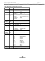
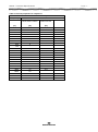
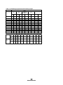
AA222 - Technical Specifications Page 1 Technical Specifications AA222 Audio Traveller Item No. 8107028-1 – 07/2014 AA222 - Technical Specifications Page 2 Included and Optional Parts Parts Included Parts: Audiometric headphone Single contralateral headset CIR33 Insert earphones B71 Bone conductor APS2 Patient Signal ATP-AT235U Universal probe system with shoulder strap and wrist strap (tubing 360mm Ø1.3xØ3.3 transparent silicone) TPR26 3 rolls of recording paper Power cable Dust cover Operation Manual. Multilingual CE instructions for use Additional Parts: EARtone 5A Audiometric Insert Phones 50250 Peltor noise exclosures 21925 Amplivox noise exclosures ACC400 carrying case CAT50 calibration unit 0.2-0.5-2.0-5.0 ml IES impedance ear simulator GSE10 RS232 Galbanic isolation adapter USB cable 2m black AA222 - Technical Specifications Page 3 General Technical Specifications Standards: Safety: EMC: Impedance: Audiometer: IEC60601-1, Class 1, Type B IEC60601-1-2 IEC60645-5/ANSI S3.39, Type 2 IEC60645-1/ANSI S3.6, Tone Type 2, Speech Type B-E Power: Consumption: Mains voltage/fuses: 15VA 100-240V~, 50-60Hz, 0.5A max. The AA222 is delivered with a power cord for the relevant national mains socket. But AA222 can be powered by any national AC voltage - Before use, the correct attachment plug/mains cable must be identified and installed. Operation Environment: Temperature: Rel. Humidity: 15 – 35 C / 65 – 95 F 30 – 90% Temperatures below 0C / 32F and above 50C / 122F may cause permanent damage to the instrument and accessories. Warm up time: 10min at room temperature (20C / 68F) Printer (Optional) Type: Printing Time: Thermal printer with recording paper in rolls. Depending on the test printed. Paper Rolls: Width: Diameter: Basis weight: Thickness: Tensile: 112 (+/- 0.5) mm 45 (+2.0) mm 58.5 +/- 3g/m2 62 +/- 3 u Min. 3.2 kN/m AA222 - Technical Specifications Page 4 Impedance Measuring System Probe tone: Frequency: Level : 226 Hz. 85 dB SPL with AGC, assuring constant level at different volumes. Air Pressure Control: Indicator: Range: Pressure Limitations: Pressure Change Rate: Compliance Range: 0.1 to 6.0 ml (Ear volume: 0.1 to 8.0 ml). No difference is measured in the recorded values between static and dynamic measuring mode. Types Tympanometry: Automatic, where the start and stop pressure can be userprogrammed from the setup menu. Eustachian Tube Function: Williams test (automatic function). Indicators Graphical display: Compliance is indicated as ml and pressure as daPa. Stimulus level is indicated as dB Hearing Level. Memory Tympanometry: Eustachian Tube Function: 1 curve per ear. 3 curves per ear. Impedance calibration properties Probe tone Frequencies: Level: Distortion: Calibrated transducers Audiometry headset: Bone conductor: -8 226 Hz ± 1%, 678 Hz ± 1%, 800 ± 1%, 85 dB SPL ± 1.5 dB measured in an IEC 60318-5 acoustic coupler. The level is constant for all volumes in the measurement range. Max 3% THD Telephonics TDH/DD45 with a static force of 4.5N 0.5N Radioear B71 with a static force of 5.4N0.5N Definition of units 1 ml at 226 Hz = 1 acoustic mmho, 3 1 acoustics mho = 10 m /Pa·s 1 daPa = 10 Pascal Automatic. Measured value is displayed on the graphical display. -600 to +300 daPa. -800 daPa and +600 daPa. Minimum (50 daPa/s), medium, maximum or automatic with minimum speed at compliance peak. Selectable in the setup. AA222 - Technical Specifications Page 5 Reflex and Audiometer Functions Signal Sources Tone – Contra, Reflex: Tone – Contra, Audiometry: Tone – Ipsi, Reflex: Noise – Contra, Reflex: Noise – Ipsi, Reflex: Noise – Audiometry: Inputs CD1/2: Mic: Talk Back: Patient Response: Output Audiometry Earphones: Bone Conduction: Free Field 1 and 2: Monitor: Contra Earphone: Ipsi Earphone: Reflex sensitivity: Reflex detection: Air: USB: Keyboard: Tolerance Probe tone: Insert earphones: Super-aural earphone: 250, 500, 1000, 2000, 3000, 4000, 6000 and 8000Hz. 125, 250, 500, 750, 1000, 1500, 2000, 3000, 4000, 6000 and 8000Hz 500, 1000, 2000, 3000 and 4000Hz. Wide Band, High Pass, Low Pass Wide Band, High Pass, Low Pass. Narrow Band (IEC60645-1) White Noise Connection for CD player or tape recorder. Connection for external microphone for live speech. Connection for talk back microphone. Patient response switch connection. Audiometric headphone, left and right. B71 bone conductor. Electrical output for external 2 channel power amplifier (AP12 and AP70). Monitor earphone disconnects the internal monitor loudspeaker when inserted. Operator can monitor signal when presented to the patient as well as the talk back signal from the patient’s microphone. Audiometric headphones for reflex and audiometry measurements. Probe earphone incorporated in probe system for reflex measurements. 0.001 ml is the lowest detectable volume change. The risk of artefacts at higher stimulus levels in reflex measurements are minor and will not activate the reflex detection system. Connection for air system to probe. Input/output for PC connection. An external PC can be setup to both monitor and control the instrument. The control actions can be followed on the display and the operation panel. Online communication can be selected, where the measured data will be sent to an external PC. Connection for external keyboard, standard PC type. frequency accuracy better than 2% frequency accuracy better than 3% frequency accuracy better than 3% THD Probe tone: Insert earphones: Super-aural earphone: THD is less than 3% THD is less than 5% THD is less than 2.5% AA222 - Technical Specifications Attenuator Range: Test Types Manual Audiometry: Automatic Audiometry: Manual Reflex: Reflex Decay: SISI: Warble: Stenger: ABLB : Page 6 0 to 130 dB in 1 or 5 dB steps. Typical range is –10 to 120 dB HL. Range is individual for different modes – see table 1. Manual control of all functions. Auto threshold according to ISO 8253-1 (Patient controlled Hughson Westlake). Threshold is determined by the activation of the patient response. Manual control of all functions. Manually controlled with stimulus duration of 10 seconds. With automatic scoring calculation (5 dB included for familiarisation. 5 Hz sine, +/-5 % modulation. Binaural pure tone or speech stimulation. Automatic loudness balance test (Fowler). Memory 6 ipsilateral and 6 contralateral graphs / curves, which each can hold up to 6 pulses. There is an additional capacity for 6 manual tests. Properties of stimuli General Specifications for stimulus and audiometer signals are made to follow IEC 60645-1 Contralateral Earphone Pure tone: Wide Band noise (WB): - spectral properties: Low pass noise (LP): - spectral properties: Hign pass noise (HP): Ipsilateral Earphone Pure tone: Wide Band noise (WB): - spectral properties: Low pass noise (LP): - spectral properties: Hign pass noise (HP): General about levels: Electrical output properties Initial Latency: Rise Time: Terminal latency: Fall time: Overshoot: Undershoot: ISO 389-1 for audiometric headphone Interacoustics standard As “Broad band noise” specified in IEC 60645-5, but with 500 Hz as lower cut-off frequency. Interacoustics standard Uniform from 500 Hz to 1600 Hz, ±5 dB re. 1000 Hz level Uniform from 1600 Hz to 10 kHz, ±5 dB re. 1000 Hz level Interacoustics standard Interacoustics standard As “Broad band noise” specified in IEC 60645-5, but with 500 Hz as lower cut-off frequency. Interacoustics standard Uniform from 500 Hz to 1600 Hz, ±10 dB re. 1000 Hz level Uniform from 1600 Hz to 10 kHz, ±10 dB re. 1000 Hz level The actual sound pressure level at the eardrum will depend on the volume of the ear. See table 2. 44.2 (+5/-0) mS 44.2 (+5/-0) mS 44.2 (+5/-0) mS 44.2 (+5/-0) mS 5 % (± 2%) 5 % (± 2%) AA222 - Technical Specifications Page 7 Table 1: Frequencies and intensity ranges Frequency Reflex Contralateral Audiometric headphone Ipsilateral EAR-Tone 3A Insert/CIR33 Hz Min dB HL Max* dB HL Min dB HL Max* dB HL Min dB HL Max* dB HL Min dB HL Max* DB HL 250 500 1000 2000 3000 4000 6000 8000 -10 -10 -10 -10 -10 -10 -10 -10 110 120 120 120 120 120 120 110 -10 -10 -10 -10 -10 -10 -10 -10 105 110 120 120 120 115 100 95 0 0 0 0 0 0 - 100 105 110 105 100 95 - 10 10 10 10 10 - 105 110 105 100 100 - WB noise LP noise HP noise -10 -10 -10 120 120 120 -10 -10 -10 120 120 120 0 0 0 100 100 100 10 10 10 105 105 105 Minimum level step size 5 dB Maximum difference error between tow steps is less than ±3 dB Residual noise is less than 25 dB (A) Signal to noise ratio is larger than 80 dB (A) ON-OFF ration is larger than 80 dB (A) Rise-/fall time: 35 ms (±10 ms) Table 2: Variation of ipsi stimulus levels for different volumes of the ear canal Freq. [Hz] 500 1000 2000 3000 4000 Variation of ipsi stimulus levels for different volumes of the ear canal Relative to the calibration performed on an IEC 126 coupler 0.5 ml 1 ml [dB] [dB] 9.7 5.3 9.7 5.3 11.7 3.9 -0.8 -0.5 -1.6 -0.8 WB LP 7.5 8.0 3.2 3.6 HP 3.9 1.4 AA222 - Technical Specifications Page 8 Table 3: General properties for earphones Sound attenuation values for earphones Freq. [Hz] 125 160 200 250 315 400 500 630 750 800 1000 1250 1500 1600 2000 2500 3000 3150 4000 5000 6000 6300 8000 Attenuation Audiometric headphone with MX41/AR or PN 51 cushion [dB] 3 4 5 5 5 6 7 9 11 15 18 21 26 28 31 32 29 26 24 EAR-Tone 3A [dB] 32.5 36 37.5 36.5 33 39.5 42.5 Difference between free field and coupler sensitivity levels. Used by Free Field equivalent earphone output (Type A-E or B-E) Freq. Correction values Audiometric headphone with MX41/AR or PN 51 cushion using IEC 303 coupler [Hz] [dB] 125 160 200 250 315 400 500 630 750 800 1000 1250 1500 1600 2000 2500 3000 3150 4000 5000 6000 6300 8000 -17.5 -14.5 -12 -9.5 -6.5 -3.5 -0.5 0 -0.5 -0.5 -1 -4 -6 -7 -10.5 -10.5 -11 -10.5 1.5 AA222 - Technical Specifications Page 9 Table 4: Reference values for stimulus and audiometer calibration Freq. Reference values for stimulus and audiometer calibration ISO 389-1 ANSI S3.6 ISO 389-4 ISO 389-3 (ISO 8798) (ISO (NB 7566) (TDH/ (TDH/DD masking) (BC) DD45) 45) [Hz] [dB [dB re. [dB re. re. 20 20 µPa] 20 µPa] µPa] 125 45, 45 0 25, 25,5 5 11, 11,5 5 7,5 8 7 7 6,5 6,5 9 9 10 10 9,5 9,5 15, 15,5 5 13 13 250 500 750 1000 1500 2000 3000 4000 6000 8000 WB LP HP ANSI S3.6 ISO 389-2 (Insert) (BC) [dB re. [dB re. 1µN] 1µN] 4 ISO 389- ISO 389- Interacoustics Standard 7 7 Free Diffuse- TDH/DD Insert Ipsi field field 45 (FF) (FF) [dB re. [dB re. [dB re. [dB re. [dB [dB re. 20 µPa] 20 20 20 re. 20 µPa] µPa] µPa] 20 µPa] µPa] 26 22,0 22,0 4 67 67 14 11,0 11,0 4 58 58 5,5 4,0 3,5 5 6 6 6 6 5 5 48,5 42,5 36,5 31 30 35,5 40 48,5 42,5 36,5 31 30 35,5 2 0 2 3 3,5 5,5 2 2,0 2,0 0,5 -1,5 -6,0 -6,5 2,5 1,0 0,5 -1,0 -1,5 -4,0 -5,0 -0,5 5 40 0 11,5 5,5 -8 -6 -10 -5 -7 -8 -5 -7 -8 ISO 389-3 / ANSI S3.6. Valid for placement on the human mastoid Coupler types used by calibration TDH/DD45 is calibrated using a 6cc acoustic coupler made in accordance to IEC 60318-3 Insert phones are calibrated using a 2cc acoustic coupler made in accordance to IEC 60318-5 Bone Conductor is calibrated using a mechanical coupler made in accordance to IEC 60318-6 AA222 - Technical Specifications Page 10 Tabe 5. Specification of input/output connections Inputs Connector type Mains connector IEC 60320-1 Type C6 Patient response Jack, 6.3mm stereo CD 1 and 2 Jack, 3.5mm stereo Electrical properties 2.5A/250V AC Handheld switch: Sensitivity: Impedance: Freq. Response: Microphone Jack, 3.5 mm Type: stereo Sensitivity: Impedance: Freq.Response: Electret bias: Talk Back microphone Jack, 6,3 mm As for Microphone stereo Signal is forced to +5V level when activated. 9 mV at max volume and 0 Vu 47.5 k 75-12000 Hz 3dB Electret or 2000 dynamic microphone. 100 V at max volume for 0 Vu reading 47.5 k 90-20kHz 6.2V through 4.75 k (1.3 mA) Outputs: Phones, Left/ Right Jack, 6.3mm mono Voltage: Min. load impedance: Up to 5.5V rms. by 10 load 5 Bone conductor Jack, 6.3mm mono Phono As for Phones, Left/Right Voltage: Min. load impedance: Freq. response: Output impedance: Up to 8.0V rms. by 100 load 100 75-12000 Hz +/-3dB 500 ohm Monitor Jack, 6.3mm mono Voltage: Min. load impedance: Up to 2.0V rms. by 8 load 0 Phones, Contralateral (Insert masking) Transducer Jack, 6.3mm mono Voltage: Min. load impedance: Up to 5.5V rms. by 10 load 5 CANON, 15 pole Pin 1: Pin 2: Pin 3: Pin 4: Pin 5: Pin 6: Pin 7: Pin 8: Pin 9: Pin 10: Pin 11: Pin 12: Pin 13: Pin 14: Pin 15: Press. 1 signal 12V -12V Remote key/detection Probe tone Mic. signal LED blue Press. 2 signal LED green Ipsi Stim. Gnd. Ipsi Stim. Signal Probe tone Gnd. Gnd. Vref., 5V LED red USB type”B” USB port for communication See appendix A in service manual for detailed information Free Field 1, 2 Data I/O: USB AA222 - Technical Specifications Page 11 Table 6: General properties for earphones. Sound attenuation values for earphones Frequency Attenuation TDH/DD45 with MX41/ EAR-Tone 3A AR or PN 51 cushion EAR-Tone 5A [Hz] [dB] [dB] 125 160 200 250 315 400 500 630 750 800 1000 1250 1500 1600 2000 2500 3000 3150 4000 5000 6000 6300 3 4 5 5 5 6 7 9 11 15 18 21 26 28 31 32 29 26 33,5 8000 24 43,5 34,5 34,5 35,0 33,0 39,5 Table 7: Audiometry frequencies and intensity ranges Frequency TDH/DD4 5 EAR-Tone 3A Audiometry Bone Insert Masking conduction NB B71 Min Max * Min Max* Min Max* Min Max* Min Max* Hz dB HL dB HL dB HL -10 -- - dB HL -10 dB HL 90 dB HL - dB HL -10 dB HL - dB HL 125 dB HL 90 110 -10 105 0 45 0 105 -10 90 110 0 65 0 110 -10 100 250 -10 Free Field 80 500 -10 120 -10 750 -10 120 -10 115 0 70 0 110 -10 100 120 -10 120 0 70 0 110 -10 100 120 -10 120 0 70 0 110 -10 100 120 -10 120 0 75 0 110 -10 100 120 0 80 0 110 -10 100 1000 1500 2000 -10 -10 -10 3000 -10 120 -10 4000 -10 120 -10 115 0 80 0 105 -10 100 6000 -10 120 -10 100 0 55 0 95 -10 95 8000 -10 110 -10 95 0 50 0 90 -10 90 Speech Speech Noise Type B -10 100 -10 90 -10 50 - - 0 100 Type B-E -10 110 -10 90 -10 50 - - 0 100 Type B -10 100 -10 90 - - 0 90 0 90 Type B-E -10 110 -10 90 - - 0 90 0 90 Note: Max values are obtainable by selecting “Ext. Range” on the instrument.