1
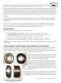
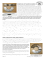
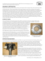
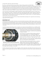
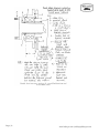
REPLACING AND MODIFYING REAR WHEEL BEARINGS ON ALL BENTLEY MKVI/R TYPES N.W.Geeson BACKGROUND AND THE PROBLEMS ARISING Rear wheel bearing failure on these cars can be a nerve racking experience besides being expensive. This type of failure is becoming very frequent and is also affecting the later Silver Cloud cars. In a recent 18 month period I have known of no less than 19 rear wheel bearing failures. All of the axle bearings and rear wheel bearings on the cars prior to about June 1952 are METRIC. Although the service manual dimensions are shown in imperial equivalent sizes the bearings are true metric. Only when the rear axle pinion bearings were changed to taper bearings circa June 1952 did the pinion bearings change to imperial. However the axle side bearings and the rear wheel bearings remained Metric, as did one of the axle side bearings during the reign of the Cloud cars. The original wheel bearings had a special inbuilt end float and the service manual warned against renewing the bearings just because the end float was present. Unfortunately this bearing end float allows the half shaft splines to also try to end float in the splined bevel wheels. Readers who are in the automotive engineering field will realise that splined shafts resist end float when under driving conditions, but when the splines do slide, they wear the half shaft splines. When the shafts do not slide, they transfer the end load directly onto the axle bevel gear thrust washers. The rear wheel bearings are about the last components that need renewal on these cars, long after the engines have worn out, however after some 50 years the bearing grease is almost non-existent and what remains is not a good lubricant. Even attempting to re-grease the bearing provides no guarantees as the cage separating the ball bearings is worn and breakage of this cage is one reason for these bearings locking up without warning. Re-greasing a bearing after a considerable period of time, without doubt, will appear to make the bearing revolve smoother. It does not however replace metal that has worn off the bearings and which is captured in its granulated state within the sealed bearing. Metal, which given time will guarantee a collapsed bearing but no guarantee is given as to whether the affected car stays on its four wheels. It is a fair certainty that the sunroof panel will eject if the car slides on its roof; if it happens to your car it gets no rosettes as this trick has been performed before. The only decision you have to make is whether your life and others are worth the cost of the bearings. Persistent running with slack and partially failed rear wheel bearings will eventually cause the bearing to turn on the half shaft and within the bearing housing. Usually not realised, although I earn my semi-retired living from the results, is that failed rear wheel bearings are one cause of failure of the main axle bearings and in fact scrapping of both the main axle case and the inner differential gear case. Turning the subject on its head, the failure of the axle side bearings will, and does, fail the rear wheel bearings. Each set of bearings support the half shaft at either end, actually indirectly through a bevel gear at the inner end, so a complete bearing failure at one end affects the other end. It is worthwhile advising on the damage to the axles when the bearing wear is allowed to become excessive. The right side axle bearing outer track is held directly in the alloy main axle case whilst the inner bearing track is mounted on the inner axle case containing the differential pinions. This inner case is bolted together by eight studs and nuts. Initial failure of either wheel bearing or axle bearing causes outer axle bearing track movement and wear in the bearing bore of the main axle case. Once worn in this way the main axle case is all but scrap. Eventually the bearing wear allows the main crown gear and pinion to try to override each other, normally on the overrun, and tooth breakage occurs. On a Cloud series II or III the Page | 1 www.kda132.com |[email protected] gear set is fairly strong and the inner axle bearing will rotate and bore into the inner axle differential gear case. In the instances of earlier cars the gear set will break first but more than often the two part inner differential gear case faces will also be fretted against each other, or the eight case studs will stretch. It is quite common to be able to remove these axle side bearings and shake the rollers out of their retaining cages; such is the amount of bearing wear. It is surprising how long the axle will hold out, but the only problem is that when it does go bang there is so much damage that the cost is very high. If a rear wheel bearing has actually failed, that is the bearing has failed on the road in a collapsed state, there is no doubt at all that the relevant rear outer axle bearing, on the failed wheel bearing side, has been affected. It is in fact impossible for such a wheel bearing total collapse to not have caused some axle long term damage. The initial failure of the wheel bearing is usually the breakage of the bearing cage, which separates the balls within the bearing. If the owner is lucky he/she hears a clicking, which sometimes disappears temporarily when the car is reversed. Unless the bearings are really badly worn it can be difficult to detect actual wear when the car is jacked up with the load relieved from the bearing and when the wheels are spun. In fact is much easier to detect the wear when the wheel is removed as any imperfect movement of the bearing is hidden by the heavy flywheel effect of the road wheel. Once the wheel is removed it becomes necessary to have a good ear and light touch, rotating the hub back and forth feeling and listening for noise and roughness. Along with this back and forth movement the half shaft needs continually indexing around to cover the full 360 degrees of the bearing. As the tooling and spares are not easily obtainable when out on the road, it is advisable to renew the rear wheel bearings unless the owner knows for sure that the bearings have been changed. Failing that, at least check the rear wheel bearings most thoroughly for any signs of wear. I can almost hear the average enthusiast saying that he / she is bound to hear the trouble arising before disaster strikes. I am afraid that does not bear out on the facts. As I mentioned initial failure is often caused by sudden cage breakage. The narrow part of the cage separating each ball wears very thin, it breaks, initially there is no noise, two balls catch up with each other and the process continues at a pace. Very quickly the balls are nearly all on one side of the bearing allowing the bearing tracks to run off parallel with each other. At 50 / 60 mph the rest is history! The other mode of rear wheel bearing failure is when the grease no longer lubricates and / or condensation has enter the bearing, resting at the bottom, it firstly erodes the track quickly followed by erosion of the balls. The rough balls either further carve up the tracks or the balls cut through the cage. Incidentally the main axle bearings also suffer this condensation erosion, usually on the right side where the inside of the vertical axle case (this part of the case cannot be seen) channels the water directly to the bearing. It does not happen so frequently on the left side as the axle side plate which carries the bearing on this side (this plate can be seen externally) is tapered and directs water usually away from the bearing. In this mode the initial roughness can be felt, when driving, of either the wheel bearing or axle bearing, it is usually mistaken for flat spots on the tyres for the first five miles or so. It will sometimes persist for many more miles as the wear takes place. From the drivers view point the problem appears to disappear because when the axle is warm the spring that pre-loads the right-hand axle bearing allows the axle bearing to move in and out each time a worn section of the bearing comes on load. This spring also moves in sympathy to disguise or mask a worn rear wheel bearing. The driver naturally believes the flat spots on the tyres have been relieved as the car attains more mileage. There is however a degree of vibration still present from the rear end normally detected through the floor pan. Unfortunately by the time a driver actually hears or feels either a rear wheel bearing or axle bearing the damage is done. History Two types of rear wheel bearing were used in production and the half shafts were also of different diameter at the bearing location, as was the bearing housing. The very early types were only used on A & B series Page | 2 www.kda132.com |[email protected] Bentley's. The changeover to the later bearing arrangement started circa Feb 1948 and the later bearings, bearing housings and half shafts can be used on the earlier cars. The conversion mentioned below is suitable for use with the following half shafts, Bentley / Silver Dawn, right-hand shaft RG4346, left-hand shaft RG4345 and Silver Wraith SWB, right-hand shaft RG 3192, left hand shaft GB 4635.All parts are identical on each half shaft assembly except for the half shafts themselves. It is also important to realise that the following only describes the bearing conversion and some parts are altered or discarded, although the basis of the bearing change does apply when replacing the original type bearings. The original rear wheel bearings are still available but very expensive. This original bearing is capable of taking side thrust loads and any replacement type must be a thrust bearing, a normal roller bearing will quickly fail. There are at least two bearings capable of replacing the original, but the owner must realise the usual disclaimers apply when a none original bearing is utilised. In the case of the original, the bearing was a single row thrust bearing which was wider in the centre section that the outer. TOLERANCES For the record the following tolerances apply on new parts: Axle shaft BEARING bore diameter = 1.7712 / 1.7717 inch ( 44.998 / 45.011 mm) Axle shaft BEARING JOURNAL diameter= 1.7723 / 1.7726 inch ( 45.017 / 45.023 mm) Axle shaft COLLAR BORE = 1.768 / 1.7685 inch ( 44.906 / 44.919 mm) Interference fit, axle shaft to BEARING = 0.0006 / 0.0014 inch ( 0.016 / 0.035 mm) Interference fit, axle shaft to COLLAR = 0.0038 / 0.0046 INCH (0.098 / 0.117 mm) NOTE. The bore of both bearing and collar MUST be lubricated with engine oil before being pressed onto the half shaft. DISMANTLING COMPONENTS AND REMOVING HALF SHAFT Remove, road wheel, brake drum, disconnect the brake rod at the equaliser, remove the brake shoes and inter shoe linkages. Undo the five nuts holding the axle tube to the bearing retaining plate / bearing housing, undo the four nuts holding the brake back plate. Note the bolt heads are prevented from rotating, so all these nuts will come off. Take the lock nut off the brake adjuster wheel, to do this slacken the adjuster right off until it will not turn any more, after removing the lock nut unscrew the brake adjuster wheel, it is threaded just like the lock nut. Move the brake actuator rubber inwards along the brake rod and then move the brake back plate off its four studs and onto the axle tube. Tap the flange of the half shaft to free the bearing housing and half shaft, and withdraw the assembly from the axle, collecting the loose brake carrier which is still bolted to the bearing retaining plate. Collect the five holding bolts. Note at this point that of the five retaining bolt holes, the ODD hole is facing towards the Brake ADJUSTER. If you don’t remember this when assembling, you will have to strip the assemblies apart again!!!! Page | 3 www.kda132.com |[email protected] First undo the four nuts, bolts and spacers holding the bearing retaining plate to the brake carrier. Do not fail to collect the spacers. Now you will see the bearing spigot plate which has a protrusion on its inner face, this needs machining off and the plate just face grinding on BOTH sides to clean it up and is discussed later. Note that this spigot plate has a taper lead on the opposite face to that face with the protrusion this taper face goes towards the axle. Clean the brake carrier and assemble the machined plate to the carrier with the four nuts, bolts, SPACERS and spring washers. Remember taper face towards axle, and odd bolt hole adjacent to the brake adjuster. REPLACEMENT BEARING TYPE I use a F.A.G 3309B 2RSR bearing made in Germany others are made in U.S.A and Japan. These 3309 bearings are of the double-sided neoprene seal type there is also an equivalent 5309 numbered bearing. Both bearings are available with steel seal shields, however due to slight construction differences on the side walls these steel type shielded bearings will foul the bearing retaining collar, unless the collar is relieved locally to the outer diameter of the steel shield. The neoprene seal types are therefore recommended only to overcome the possible fouling problem. The 3309 bearing is nominally 100 mm x 45mm x 40 mm wide and unlike the original; it is a massive double row thrust ball bearing, the inner and outer tracks being of the same width. The conversion described is based on this 3309 neoprene sealed type bearing. This particular heavy bearing was chosen because it has far greater load carrying capacity than the original bearing and the wider outer track enables the wheel loading to be evenly spread along the wheel bearing housing. In addition the width of the bearing is usually the same as the housing depth and enables machining to be kept to a minimum to provide a pre-fit of 0.001 inch. Replacement using the original bearing or any single row type will at least require re-machining of the outer bearing spacer and if this is already undersized then a new spacer must be machined out of 4 inch (100mm) steel stock. In any even the replacement bearing must not be allowed to end float within the bearing housing and will need a protrusion from the housing when the bearing is fitted of at least 0.001 inch. This amount allows a zero end load when the bearing housing flange has been covered in sealer and the assembly fitted to the axle. The various workshop manuals describe the removal of the half shaft assemblies, which are removed complete with bearings and bearing housings, and also a spigot plate and bearing spacer ring. In the case of a straight forward replacement of the original type bearing it was always intended that the bearing spacer ring was to be face ground in order to just pre-load the new bearing, as previously mentioned. This is a point often disregarded when the original bearings are replaced and in particular when they are replaced as a result of a failure on the road .In the case of the suggested bearing conversion this spacer ring is discarded. Page | 4 www.kda132.com |[email protected] REMOVAL OF THE OLD BEARING After removal of the half shaft it is necessary to mount the shaft in a lathe and turn down the bearing retaining collar until about 0.010 inch remains when it is easy to split and remove the remaining collar with a chisel, without damage to the shaft surface. It is important that the integrity of the shaft surface at this point is protected because eventually a new retaining collar will have to be pressed on to the shaft and it is only the interference fit between the collar and shaft plus the bearing fit, which retains the road wheel and bearing assembly. An alternative would be to use an angle grinder or cutter and remove the collar without damaging the shaft. Using a lathe does enable the straightness of the shaft to be checked as any out of truth will wear both axle and wheel bearings and take its toll on the half shaft splines. Once the retaining collar is removed the bearing spring (Belleville washer) can be discarded as can the bearing spacer ring, which is loose in the bearing housing. At this point it is necessary to mount the shaft in a hollow hydraulic press bed and provide a suitable support for the bearing housing whilst the shaft is pressed through and therefore off the bearing. My own supports are made of a steel circular section some 9 inches in diameter and 1.250 inch thick. This circular section was then machined to fit around the bearing housing with an integral step, this step was lathe turned to fit the step in the bearing housing and then finally the circular section was sawn across the centre. This tool then forms two "U" shaped sections, which completely surround and support the bearing housing whilst the pressing operation is in progress. It is very important that the flange of the bearing housing, which is about 0.125 inch thick, is not used to support the housing during pressing operations. The bearing housing STEP must take the load and if any load is applied to the flange, distortion and subsequent water entry will result. There is also a very serious possibility of the flange breaking away at some time in the future. By this time the wise owner will no doubt realise the wisdom of replacing these bearing whilst the car is in his / her own garage or with a specialist of their choice and not risking a distress purchase out on the open road. REPLACEMENT OF THE NEW BEARING Once the shaft has been pressed off the bearing it is necessary to recover the bell shaped spacer from the flange end of the shaft. This spacer positions the bearing the correct distance from the end of the shaft, and in doing so, sets the final running clearance between the brake back plate and the edge of the brake drum, clean off the spacer faces and the opposing half shaft face and replace the spacer immediately. As the conversion 3309 bearing has a different centre section width from the original it is necessary to ADD another spacer to the original bell shaped spacer. The extra spacer is 1.775 inch internal diameter, 0.205 inch thick and 2.30 inch outer diameter. Ideally this spacer needs to be made of some reasonable material like EN24T or EN36 to prevent crushing. This extra spacer should be placed on the half shaft, now, so that its placement is not forgotten. Press out the old bearing from the housing. Examination of the housing flange will no doubt show that some water ingress has taken place and rust is present on the flange face. Initially check the flange of the bearing housing to ensure it is flat and Page | 5 www.kda132.com |[email protected] not distorted, if any out of truth is present it MUST be faced off, keeping any metal removal to within approximately 0.005 inch. BEARING PROTRUSION Measure the thickness of the bearing and the actual depth of the bearing housing to the internal step where the bearing locates. These measurements will be approximately 1.5615 inch (39.66mm) if the bearing housing flange has not been faced off. The measurements finally will require adjusting by machining either the flange face or housing internal step to ensure that the bearing is thicker than the housing depth by 0.001 inch. In other words when the bearing is fitted to the housing it should protrude by 0.001 inch. This protrusion allows for a thin film of sealer to be applied to the bearing housing flange, and also ensures that when the bearing housing is re-bolted to the spigot plate the plate will actually contact the bearing and stop any bearing end float or looseness. In simple terms the bearing will be trapped hard between the spigot plate and bearing housing. Normally even making allowances for truing up the housing flange no more than 0.0010 inch needs removing from either the flange or the housing step. SPIGOT PLATE Next, examination of the bearing spigot plate will show a location protrusion or spigot, which needs machining off the plate and the plate face grinding to finish. This protrusion originally contacted the original bearing spacer ring, which has now been discarded, it should also be said that the protrusion did provide a spigot to assist in centralising the assembly. However the bearing housing attachment bolts and their holes are very accurate in size and circular pitch dimension, and therefore centralisation and the retention under load appears well catered for, even when the assistance of the spigot is lost. Note that it is necessary to dismantle the rear brake assembly to extract the bearing spigot plate!! This spigot plate is shown in most parts lists on plate K1 and is the item shown nearest the half shaft splines, it is not individually numbered, and the illustration does not show the spigot section on this plate. The bearing spacer ring, to be discarded, is also show on plate K1 and is the second item inwards from the half shaft splines. The plate spring (Belleville washer) also to be discarded is shown as the fourth item from the splined end of the shaft. FITTING THE BEARING Having prepared the bearing housing it is possible now to press the bearing into the housing, taking care to only exert pressure on the OUTER bearing track. Then after making sure that the original bell shaped spacer and new spacer are both positioned on the half shaft beforehand, the shaft can be pressed through the centre of the bearing and its housing. Make sure the original bell shaped spacer is orientated correctly with its large diameter against the flange of the half shaft. When pressing the bearings onto the shaft journal, the bearing MUST be supported by its INNER track, certainly not the housing flange, and the applied pressure, on the end flange of the half shaft, must be in the region of 6 to 10 tons. Following this operation a new bearing retaining collar part number GB 4956 must be pressed onto the shaft with a minimum pressure of 15 tons and preferably 20 tons. Note that the retaining collar will be about 0.125 inch short of fully engaging the half shaft bearing Page | 6 www.kda132.com |[email protected] journal when it has been pressed into place. In order to visualise both the bearing and the collar pressing operations, the half shaft flange end, that is the end where the wheel lug studs are positioned, is upwards and takes the force of the hydraulic pressing ram, whilst both bearing and /or collar are in contact with a piece of tubular steel, which is supported by the cross beams of the press bed. The aforementioned piece of tubular steel needs to be made wide enough to be supported by the cross beams of the press bed and thick enough to stand 20 tons that is about 0.750 inch! In addition it needs a raised section or up stand of approx. 0.250 inch, some 2.150 inch (54.61 mm) outside diameter and the whole block needs boring through the centre 1.80 inch (45.72 mm), which makes it a tube. Visually this looks like a large steel ring with a smaller ring placed on the top. The up stand or smaller ring is sized so that it contacts the INNER bearing track or collar depending on which operation is being performed, and the bored hole allows it to pass over the 1.772 inch (45 mm) half shaft diameter where the bearing is fitted. After the bearing and retaining collar are fitted, the half shaft assembly can be replaced once the bearing spigot plate has been refitted. BUILDING UP Clean the face of the axle tube. If you have removed the brake back plate do NOT forget to replace it on the axle tube before proceeding further. Do not on any account attempt to paint the outside edge of the bearing housing flange before the assembly has been replaced. The outer flange of this housing is an exact fit inside of the bearing spigot plate and paint will only be shed off and prevent the mating flange face surfaces from contacting. Coat the bearing housing flange with a very light coat of sealer. Enter the half shaft very carefully into the axle tube and engage the axle bevel wheel splines. Be careful when conducing this exercise not to damage the axle leather oil seal through which the half shaft splines must pass. Position the five bolts through the bearing plate and onto the axle tube fit the special spring washers and nuts and tighten. Do NOT use any other bolts except the originals. You will need to centralise the brake adjuster and brake shoes as per the manual. It is vital that the adjuster is centralised BEFORE the shoe inter linkage is fitted. Then replace the brake back plate onto the four studs, then the adjuster wheel, then its lock nut, followed by the actuator rubber. Note there is a steel washer then a rubber between the rear of the adjuster and the back plate. If the brake adjuster is disassembled, mark one adjuster tappet and one end before stripping, the tappets are handed!!! The brake actuator can be stripped by first removing the tin end cap. Removing the actuator tappets complete with ROLLERS after displacing the split pins and then pushing the rod and wedge outwards. Do not lose, or forget the return spring fitted behind the wedge. Refit any adjuster or actuator. Finally build up the foundation brakes completely, fit the brake drum and adjust the brakes. Reconnect the brake rod to the equaliser and ensure the rubber boot is positioned correctly on the actuator. Refit the road wheel. Page | 7 www.kda132.com |[email protected] Page | 8 www.kda132.com |[email protected]