1
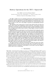
Program Processes
Pro
Version: 1.0
User’s Manual
Created by
Simanima
Table of Contents
Page
Program Processes Pro Overview ................................................................................................... 4
1.0
Running and Navigating Program Processes Pro ............................................................... 5
1.1
Starting the Program......................................................................................................... 5
1.2
Navigating the Tool .......................................................................................................... 5
1.3
User Input Selections ....................................................................................................... 6
1.3.1
Product Unit-Value ................................................................................................... 7
1.3.1.1
Unit-Value Types .............................................................................................. 7
1.3.1.1.1 Select by Product Unit-Value Level ................................................................ 8
1.3.1.1.2 Select by Product Type .................................................................................... 9
1.3.1.1.2.1 Sort Product Types .................................................................................. 10
1.3.1.1.2.1.1 Sort Order ......................................................................................... 10
1.3.1.1.2.1.2 Sort Type .......................................................................................... 10
1.3.1.1.2.2 Filter Product Types by Unit-Value ........................................................ 10
1.3.2
1.4
Generate Program Processes List............................................................................ 11
Main Menu Drop-Down Menus ..................................................................................... 12
1.4.1
File .......................................................................................................................... 12
1.4.1.1
New .................................................................................................................. 13
1.4.1.2
Open................................................................................................................. 13
1.4.1.2.1 Open Project Options..................................................................................... 13
1.4.1.3
Save ................................................................................................................. 14
1.4.1.4
Save As ............................................................................................................ 14
1.4.1.4.1 Save Project Options ..................................................................................... 14
1.4.1.5
Exit................................................................................................................... 15
1.4.2
View ........................................................................................................................ 15
1.4.3
Help ......................................................................................................................... 16
1.5
Buttons Toolbar .............................................................................................................. 18
1.5.1
New ......................................................................................................................... 19
1.5.2
Open ........................................................................................................................ 19
1.5.3
Save ......................................................................................................................... 19
2
2.0
Results ............................................................................................................................... 20
2.1
Sort Menu ....................................................................................................................... 20
2.1.1
Sort Order................................................................................................................ 21
2.1.2
Sort Type ................................................................................................................. 21
2.2
Results Drop-Down Menu ............................................................................................. 21
2.2.1
Save As ................................................................................................................... 21
2.2.2
Export Results to Excel File ................................................................................... 21
2.2.3
Print Results ............................................................................................................ 23
2.2.4
Close Results Window ............................................................................................ 23
3.0
Acronyms .......................................................................................................................... 24
4.0
Terms and Definitions....................................................................................................... 26
3
Program Processes Pro Overview
The Program Processes Pro software tool allows the User to generate a list of recommended
Mission Assurance program processes based on a specified product type or unit-value. The
Mission Assurance program covers Reliability, Maintainability, Availability, and Dependability
(RMAD), System Safety, and Quality Assurance (QA) programs. This tool is complaint with S102 Mission Assurance Standards.
4
1.0
Running and Navigating Program Processes Pro
1.1
Starting the Program
If the Program Processes Pro icon (Fig.1.1-1) is on the Desktop, double-click it to execute the
Program Processes Pro software tool.
Figure 1.1-1. Program Processes Pro Icon
If the icon is not on the Desktop, go to the Start Menu. Under the All Programs listing, look for
a program folder titled Simanima. Within the Simanima folder, look for the Program Processes
Pro folder. Select the Program Processes Pro program, contained in the Program Processes
Pro program folder. It is recommended that a shortcut to the program be created and placed on
the Desktop, if one does not already exist. This can be done by right-clicking the Program
Processes Pro executable located in the installation location and selecting Create Shortcut.
1.2
Navigating the Tool
After the splash screen has disappeared, which is displayed for a short time when the program is
executed, the main menu of the Program Processes Pro tool is displayed as shown in Figure 1.21.
5
Drop-down
Menus
Buttons
Toolbar
User Input
Selection
Figure 1.2-1. Program Processes Pro Main Menu
The main menu is comprised of three (3) major areas:
1.3
•
User Input Selections
•
Drop-down menus
•
Buttons toolbar
User Input Selections
The User Input Selections area allows the User to select the Product Unit-Value.
6
Once the User has selected the desired input, results based on the input selection are generated
by left-clicking the Generate Program Processes List button (Fig. 1.3-1).
Generate
Program
Processes List
Button
Figure 1.3-1. Generate Program Processes List Button
1.3.1
Product Unit-Value
Program Processes Pro software tool provided multiple options for specifying the Product UnitValue. These options are listed under Unit-Value Type (see section 1.3.1.1 for details).
1.3.1.1
Unit-Value Types
As shown in Figure 1.3.1.1-1, the product unit-value can be selected using one of following two
methods:
1. Select by specific Product Unit-Value Level
2. Select by specific Product Type
7
Figure 1.3.1.1-1. Unit-Value Type Selection
1.3.1.1.1 Select by Product Unit-Value Level
The User can specify the Product Unit-Value Level even if a specific product type is not known,
but a general understanding of the unit-value level of the product is known. To select a product
unit-value, left-click the option next to the unit-value level. Only one unit-value level can be
selected at a time.
Figure 1.3.1.1.1-1. Product Unit-Value Level
8
1.3.1.1.2 Select by Product Type
The User can specify the unit-value by selecting one of the provided Product Types. To select a
Product Type, left-click the specific product type from the list of product types (Fig. 1.3.1.1.2-1).
Only one product type can be selected at a time.
Figure 1.3.1.1.2-1. Product Type Selection
9
1.3.1.1.2.1 Sort Product Types
Sort Options
Figure 1.3.1.1.2.1-1. Sort Options
1.3.1.1.2.1.1 Sort Order
The Product Types list can be sorted alphabetically in ascending order by selecting “A to Z” or
descending order by selecting “Z to A”.
1.3.1.1.2.1.2 Sort Type
In addition to sorting the Product Types list by order, the list can also be sorted by “Product
Name” or by “Unit Value”.
1.3.1.1.2.2 Filter Product Types by Unit-Value
Filter Options
Figure 1.3.1.1.2.2-1. Filter Options
The Product Types list can be filtered by selecting or deselecting the Unit-Value check boxes.
The Product Types list will only display the unit-values that have check marks in the check
boxes.
10
1.3.2
Generate Program Processes List
As shown in Figure 1.3.2-1, the User input selection will be displayed on the Results screen.
Depending on the User inputs, the following outputs will be displayed for the Mission Assurance
Program:
•
The processes that comprise the Mission Assurance program for the User defined product
unit-value;
•
The reference S-102 standard numbers for each of the program processes;
•
The Parent SR&QA program for each of the program processes;
•
The program domain of each process; and
•
A purpose of each of the Mission Assurance program processes.
From the Results Screen the project can be saved to a file (see section 1.4.1.4 for details) or
export to an Excel spreadsheet file (see section 2.2 for details).
NOTE: Product Type is only displayed in the Results screen if the User has selected a Product
Type to identify the product unit-value. If the User selects to only provide the unit-value
by level, then Product Type will not be displayed.
User
Inputs
Mission
Assurance
Processes for
selected
Product UnitValue
Program
Applicability
Standard
Reference
Numbers
Figure 1.3.2-1. Results Screen
Program
Domain
11
Process
Purpose
1.4
Main Menu Drop-Down Menus
The available program Drop-Down menus are located at the top right corner of the screen, as
shown in Figure 1.4-1. The Drop-Down menu has the following main options:
•
File
•
View
•
Help
Drop-Down Menus
Figure 1.4-1. Drop-Down Menus
1.4.1
File
To get to the File menu, left-click on File, which is located in the drop-down menus near the top
left side of the screen (Fig. 1.4-1). The File drop-down menu focuses on project file handling
functions and contains the following options:
12
•
New
•
Open
•
Save
•
Save As
•
Exit
1.4.1.1
New
To start a new project, go to File ---
then select New. A new project will be created.
NOTE: Only one (1) project can be open and worked on at a time.
1.4.1.2
Open
To open a saved project, go to File ---
then select Open. A dialog box will appear that can be
used to navigate and select a project file to open.
1.4.1.2.1 Open Project Options
Figure 1.4.1.2-1 shows the Open dialog box. A project file can be opened by either one of three
ways:
1. Double-click a file listed in the Available file(s) section of the dialog box
2. Select a file listed in the Available file(s) section of the dialog box, then press the Open
button.
3. Type a file name into the File Name text box, then press the Open button.
NOTE: Only project files with format and extension “.pppf” can be opened by this program.
13
Current
directory
location
Available
files.
Open
button.
Selected
file name
Figure 1.4.1.2-1. Open project dialog box
1.4.1.3
Save
Once a Project has been saved under a specified file name, if the User is still working on that
same project file, then the project can be re-saved quickly by using the Save option. To use the
Save option, go to File --- Save.
1.4.1.4
Save As
To save a project file and label it with a specific name, go to File ---
Save As ---
Save As
*.pppf Project. A dialog box will appear that can be used to name and save the current project
file to a specified location.
1.4.1.4.1 Save Project Options
The Save dialog box is shown in Figure 1.4.1.4-1. A project file can be saved by either one of
three ways:
1. Double-click a file listed in the Existing file(s) section of the dialog box to save over and
existing file.
2. Select a file listed in the Existing file(s) section of the dialog box, then press the Save
button to save over and existing file.
3. Type a file name into the File Name text box, then press the Save button.
14
Current
directory
location
Existing
files.
Save
button.
File
Name.
Figure 1.4.1.4-1. Save project dialog box
The project file extension will be “.pppf”.
NOTE: If the project file already exists, the User will be prompted to confirm that they wish to
overwrite an existing project.
1.4.1.5
Exit
The Exit option will exit the Program Processes Pro program. To initiate the Exit option, go to
File ---
1.4.2
Exit.
View
To get to the View menu, left-click on View, which is located in the drop-down menus near the
top left side of the screen (Fig. 1.4-1). The View drop-down menu provides the option to view
results of a recent output or of a project that has been recently opened. From the View dropdown menu, select View Results to display generated/loaded results. The results window will
appear (Fig. 1.4.2-1).
15
Figure 1.4.2-1. Results Screen
NOTE: If no results have been generated or loaded, then the following message will be displayed
to notify the User that results are not available (Fig 1.4.2-2).
Figure 1.4.2-2. Results Not Currently Available Notification
1.4.3
Help
To get to the Help menu, left-click on Help, which is located in the drop-down menus near the
top left side of the screen (Fig. 1.4-1). The Help drop-down menu contains the About and User’s
Guide options. From the Help drop-down menu, select About to display an information screen
about the Program Processes Pro software tool (Fig. 1.4.3-1). To open a PDF version of the
User’s Guide for this tool, select User’s Guide from the Help drop-down menu.
16
Figure 1.4.3-1. About Screen
17
1.5
Buttons Toolbar
As shown in Figure 1.5-1, Program Processes Pro software tool provides buttons for quick
access to the following functions that are performed on projects:
•
New
•
Open
•
Save
Button Toolbar
Figure 1.5-1. Button Toolbar
18
1.5.1
New
Left-click the New button to create a new project.
NOTE: Only one (1) project can be open and worked on at a time.
1.5.2
Open
The Open button provides quicker access to the Open project dialog box. For details on the
dialog box, see section 1.4.1.2.1 for details.
1.5.3
Save
Once a Project has been saved under a specified file name, if the User is still working on that
same project file, then the project can be re-saved quickly by left-clicking the Save button.
19
2.0
Results
The Results window appears immediately after the Generate Program Processes List button is
selected (see section 1.3.4 for details) from the main menu or View Results (see section 1.4.2 for
details) is selected from the drop-down menu of the main menu.
Sort Menu
Drop-Down
Menus
Mission
Assurance
Processes for
selected
Product UnitValue
Program
Applicability
Standard
Reference
Numbers
2.1
Figure 2.0-1. Results Screen
Program
Domain
Process
Purpose
Sort Menu
The Results windows offers Sort capabilities located at the top right corner of the screen, as
shown in Figure 2.0-1. The Sort menu allows the results to be sorted the following ways:
•
Sort Order
•
Sort Type
20
2.1.1
Sort Order
The results can be sorted alphabetically in ascending order by selecting “A to Z” or descending
order by selecting “Z to A”.
2.1.2
Sort Type
In addition to being able to sort the results alphabetically, the results can also be sorted by the
following:
•
Mission Assurance Process
•
Reference S-102 Standard
•
Parent SRQA Program
•
Program Domain
•
Process Purpose
2.2
Results Drop-Down Menu
The Results windows offers a Drop-Down menu located at the top right corner of the screen, as
shown in Figure 2.0-1. The Drop-Down menu has the following options:
•
Save As
•
Export Results to Excel File
•
Print Results
•
Close
2.2.1
Save As
See section 1.4.1.4 for details.
2.2.2
Export Results to Excel File
To export results into Excel, left-click on File, which is located in the drop-down menus near the
top left side of the Results screen (Fig. 2.0-1). In the File drop-down menu, select Export Results
to Excel File. Once selected, a dialog screen will appear that will allow the User to specify the
21
file name and location to save the Excel file that will have the results exported to (Fig. 2.2.2-1).
An example of the Excel export file is shown in Figure 2.2.2-2.
NOTE: This feature utilizes Microsoft® Excel® and requires that it is already installed.
Current
directory
location
Existing
files.
Save
button.
File
Name.
Figure 2.2.2-1. Save Export Data To Excel Dialog
Figure 2.2.2-2. Exported Result in Excel
22
2.2.3
Print Results
To print the result of a current output, left-click on File, which is located in the drop-down menus
near the top left side of the Results screen (Fig. 2.0-1). In the File drop-down menu, select Print
Results. Once selected, a dialog screen will appear that will allow the User to specify the printer
options (Fig. 2.2.3-1). To start printing, left-click the Print button.
Selected
Printer
Print
Orientation
Number
of Copies
Include
Page
Numbers
2.2.4
Sides per Page
Start
Printing
Figure 2.2.3-1. Printer Options
Close Results Window
To close Results window and return back to the main menu, left-click on File, which is located in
the drop-down menus near the top left side of the Results screen (Fig. 2.0-1). In the File dropdown menu, select Close. Even though the Results window is closed, the results of the last run
can be viewed by using the View option from the Main Menu (see section 1.4.2 for details).
23
3.0
Acronyms
Ao
Availability Analysis
CA
Criticality Analysis
CIRM
Critical Item Risk Management
CN
Criticality Number
DCA
Design Concern Analysis
Do
Dependability Analysis
ESS
Environmental Stress Screening
ETA
Event Tree Analysis
ETC
Estimate to Complete
FDM
Functional Diagram Modeling
FMEA
Failure Mode and Effects Analysis
FMECA
Failure Mode, Effects, and Criticality Analysis
FRACAS
Failure Reporting, Analysis, and corrective Action
FRB
Failure Review Board
FTA
Fault Tree Analysis
HA
Hazard Analysis
HW
Hardware
LLAA
Lessons Learned Approval Authority
LOE
Level of Effort
MAP
Mission Assurance Program
MAPP
Mission Assurance Program Plan
MAWG
Mission Assurance Working Group
MCLP
Multiple Capability Level Process
PMP
Parts, Materials & Processes
PoF
Physics of Failure
QA
Quality Assurance
R&M
Reliability and Maintainability
RD/GT
Reliability Development/Growth Testing
RMAD
Reliability, Maintainability, Availability and Dependability
24
SCA
Sneak Circuit Analysis
SCLP
Single Capability Level Process
SEC
Standards Executive Council
SPFM
Single Point Failure Mode
SR&QA
Safety, Reliability & Quality Assurance
SSP
System Safety Program
SW
Software
TAAF
Test, Analyze and Fix
V&V
Verification & Validation
25
4.0
Terms and Definitions
The definitions contained in this section were taken from the S-102.0.1 Mission Assurance
Program General Requirements Standard.
anomaly
apparent
problem
or
failure
affecting
a
configured
product,
process,
or
support
equipment/facilities that is detected during product verification or operation.
NOTE: Anomalies are distinguished from discrepancies, product defects which do not violate
project requirements which may or may not be documented in the FRACAS.
acquisition authority
an organization (Government, contractor, or subcontractor) that levies requirements on another
organization through a contract or other document.
approximation1
a value that is nearly but not exactly correct or accurate.
audit
an independent examination of accounts and records to assess or verify compliance with
specifications, standards, contractual agreements, or other criteria (Ref. IEEE STD 1624-2008).
baseline process
the minimum set of functions that constitute a specific type of process.
baseline program
the minimum set of functions that constitute a specific type of program.
1
Definition source: IEEE 100, The Authoritative Dictionary of IEEE Standards Terms
26
capability
one or more processes or activities that describe how SR&QA programs are used, treated, or
developed within an organization (Ref. IEEE STD 1624-2008).
capability-based mission assurance program
the set of processes that assesses and controls product deficiency risk at one or more predefined
capability levels.
capability level
measure of the ability of a mission assurance process, as specified by a set of activities, to
address the pertinent mission assurance needs of a systems engineering process.
capability level growth
a measurable improvement (e.g., an increase in resources, scope of effort, or maturity of input
data) in the ability of a mission assurance process to support the mission assurance needs of a
systems engineering process.
chaos
the random occurrence of unpredictable and unrelated events.
control
a method used to reduce the consequences, likelihood, or effects of a hazard or failure mode
NOTE: Controls include special design features, procedures, inspections, or tests.
credible failure mode or hazard
a failure mode or hazard with a probability of occurrence greater than 1.0E-6, 0.000001, or one
in a million.
27
engineering judgment
a properly trained engineer’s technical opinion that is based on an evaluation of specific data and
personal experience.
NOTE: Engineering judgments are a reality that cannot not be avoided when insufficient time,
data, or funding are available to perform a detailed quantitative analysis. (See Sections
5.5.1 and 5.5.2 for more information.)
environmental safety assurance
to give appropriate consideration to potential environmental impacts prior to beginning any
action that may significantly affect the environment.
estimation
a tentative evaluation or rough order magnitude calculation
failure
termination of the ability of a unit to perform its required function
NOTE: A fault may cause a failure.
failure mode
consequence of the mechanism through which a failure occurs, or the manner by which a failure
is observed.
fault2
[1] [Software reliability] a manifestation of an error in software; [2] [Hardware reliability] any
undesired state of a component or system; [3] [Components] a defect or flaw in a hardware or
software component; [4] [Human reliability] procedure (operational or maintenance) or process
(manufacture or design) that is improperly followed;
NOTE: [1] An accident may cause a fault; [2] A fault may cause a failure; [3] A fault does not
necessarily require failure.
2
Definition source: IEEE 100, The Authoritative Dictionary of IEEE Standards Terms
28
hazard
a condition that is prerequisite to a mishap and a contributor to the effects of the mishap.
NOTE: A single point failure mode (SPFM) item is a hazard with respect to its potential to lead
directly to loss of a safety-critical or mission-critical system function.
maturity level
measure of the degree of accuracy of a data product, as developed using a specified set of input
data, in relation to what is considered the best achievable results.
mishap
an unplanned event or series of events resulting in death, injury, occupational illness, or damage
to or loss of equipment or property, or damage to the environment.
mission
the purpose and functions of the space system (sensors, transponders, boosters, experiments, etc.)
throughout its expected operational lifetime, and controlled reentry or disposal orbit time period.
A space system may have multiple missions (e.g., primary mission, ancillary mission, and safety
mission).
mission assurance
the program-wide identification, evaluation, and mitigation or control of all existing and
potential deficiencies that pose a threat to system safety or mission success, throughout the
product’s useful life and post-mission disposal.
NOTE: Deficiencies include damaging-threatening hazards, mission-impacting failures, and
system performance anomalies that result from unverified requirements, optimistic
assumptions, unplanned activities, ambiguous procedures, undesired environmental
conditions, latent physical faults, inappropriate corrective actions, and operator errors.
mission capability
This term encompasses the purpose and functions of the space system (sensors, transponders,
etc.) throughout its intended system mean mission duration (the expected life of the space
vehicle). (Ref. AFMAN 91-222 SUPL1).
29
mitigation
(1) a method that eliminates or reduces the consequences, likelihood, or effects of a hazard or
failure mode; (2) a hazard control.
modeling
act of producing a representation or simulation of one or more items.
non-credible failure mode or hazard
a failure mode or hazard with a probability of occurrence equal to or less than 1.0E-6, 0.000001,
or one in a million.
NOTE: In System Safety Engineering, the qualitative probability values of an improbable hazard
and a non-credible hazard are equivalent.
plan
a method for achieving an end.
practice
one or more activities that use specified inputs to develop specified work products for achieving
specified objectives (Ref. IEEE Standard 1624-2008).
process-based lesson learned
important information created, documented, and retrieved according to a process or procedure
descriptor.
product-based lesson learned
important information created, documented, and retrieved according to a system or device life
cycle specific functional or physical descriptor.
30
program
[1] the managed collection of an organization’s practices that is structured to ensure that the
customers’ requirements and product needs are satisfied (Ref. IEEE Standard 1624-2008); [2] a
defined set of managed processes conducing to an end under a single plan.
NOTE: A program does not have to consist of related, managed process. Compare with definition
of “system”.
process
a sequence of tasks, actions, or activities, including the transition criteria for progressing from
one to the next, that bring about a result (Ref. IEEE Standard 1624-2008).
NOTE: A process can be unmanaged or managed. An unmanaged or "free" process does not
have its inputs or outputs controlled. The rain and melted snow that replenishes a lake is
an example of an unmanaged process. A managed or "controlled" process has its inputs
and outputs controlled. An electrical power station is an example of a managed process.
quality
a measure of a part’s ability to meet the workmanship criteria of the manufacturer.
NOTE: Quality levels for parts used by some of the handbook methods are different from quality
of the parts. Quality levels are assigned based on the part source and level of screening
the part goes through. The concept of quality level comes from the belief that screening
improves part quality.
reliability
probability that an item will perform its intended function for a specified interval under stated
conditions.
residual risk
risk associated with significant failure modes or hazards for which there are no known control
measures, incomplete control measures, or no plans to control the failure mode or hazard.
31
root cause(s)
most fundamental reason(s) an event might or has occurred.
root cause analysis
a process for identifying the fundamental cause of an event or failure.
safety
freedom from those conditions that can cause death, injury, occupational illness, or damage to or
loss of equipment or property, or damage to the environment.
safety critical
a term applied to a condition, event, operation, process or item of whose proper recognition,
control, performance or tolerance is essential to safe system operation or use; e.g., safety critical
function, safety critical path, safety critical component.
specialty engineering
a subgroup of the engineering processes that make up the Mission Assurance Process
Note: Traditionally, this subgroup includes Reliability, Maintainability, PMP, Survivability, and
Supportability.
system
[1] a defined set of related processes.
[2] elements of a composite entity, at any level of complexity of personnel, procedures,
materials, tools, equipment, facilities, and software, that are used together in an intended
operational or support environment to perform a given task or achieve a specific purpose,
support, or mission requirement.
NOTE: A system that consists of one or more unmanaged processes is susceptible to becoming
“unbalanced” and changing over time (e.g., an ecological system). For a system to
maintain stability it must be “balanced” and consist only of managed processes.
32
system safety
the application of engineering management principles, criteria, and techniques to optimize all
aspects of safety within the constraints of operational effectiveness, time, and cost throughout all
phases of the system lifecycle (Ref. MIL-STD-882C).
systems engineering
An interdisciplinary approach encompassing the entire technical effort to evolve and verify an
integrated and life-cycle balance set of system product and process solutions that satisfy
customer needs. (Ref. MIL-STD-499B Draft).
tailoring
process by which the individual requirements (tasks, sections, paragraphs, words, phrases, or
sentences) of a standard are evaluated to determine the extent to which each requirement is most
suited for a specific system acquisition and the modification of these requirements, where
necessary, to ensure that each tailored document invokes only the minimum needs of the
customer.
timely
performance of a task, subtask, or effort when planning and execution results in the output being
provided with sufficient time for management, if need be, to identify and implement costeffective action.
EXAMPLE:
An action that avoids or minimizes schedule delays and cost increases.
validation
the act of determining that a product or process, as constituted, will fulfill its desired purpose
verification
the process of assuring that a product or process, as constituted, complies with the requirements
specified for it
33