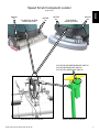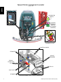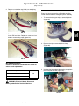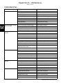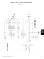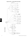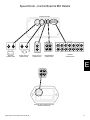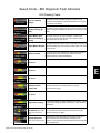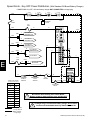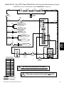
1
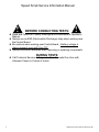
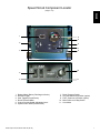
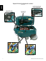
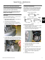
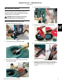
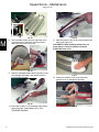
®
SPEED SCRUB ®
AUTOMATIC SCRUBBER
The Safe Scrubbing Alternativer
Quick- Traint Controls
SERVICE INFORMATION MANUAL
9002377
Rev. 01 (09-2006)
www.nobles.com
*9002377*
A
B
FOR REPLACEMENT PARTS
Identify machine model and serial number.
1. (A) Identify the machine model.
2. (B) Identify the machine serial number from the data label.
Refer to the NOBLES Speed Scrub Parts Manual.
NOTE: Only use NOBLES supplied or equivalent parts. Parts and supplies may be ordered
online, by phone, by fax or by mail.
Tennant Company
PO Box 1452
Minneapolis, MN 55440
Phone: (800) 553--8033 or (763) 513--2850
www.nobles.com
FaST--PAK is a US registered and unregistered trademark of Tennant Company.
Specifications and parts are subject to change without notice.
Copyright E 2006 TENNANT Company, Printed in U.S.A.
ii
Nobles Speed Scrub 9002377 REV.00 (08-06)
Speed Scrub Service Information Manual
Table of Contents
page
MACHINE INFORMATION
Component Locator……………………….…...……………………………..……1
Machine Specifications………...…………………….……………………………5
MAINTENANCE
SAFETY LABELS………………………..…………………………………………7
BATTERY INSTALLATION…………………………………………………………
8
SQUEEGEE REMOVAL & INSTALLATION…………………………………… 8
CIRCUIT BREAKERS & FUSES…………………………………………………9
CHARGING BATTERIES………………………..…………………………………9
Battery Charger Specifications…………………………….……………... 9
On-Board Battery Charger Settings……………………………………… 9
Using the On-Board Battery Charger………………………………………10
On-Board Battery Charger Error Codes……………………………………
11
Using an Off-Board Battery Charger………………………………………11
ADJUSTING SCRUB HEAD BRUSHES…………………………………………12
Disk Brush Model………………...………………………………………. 12
Cylindrical Brush Model……………………………………..………………12
Adjusting an Uneven Brush Pattern…………………………………13
Adjusting a Tapered Brush Pattern…………………………………13
MACHINE MAINTENANCE……………………………………………..…………14
Daily Maintenance…………………………………………..………………14
Monthly Maintenance………………………………….……………………16
Battery Maintenance……………...………..……………………………… 17
Squeegee Blades……………………….…………………...………………17
Motor Maintenance……………………………………….…………………18
FaST System Maintenance……………………………………….…………
18
JACKING UP MACHINE……………………….……...……………………………
19
TRANSPORTING MACHINE…………………….……………...…………………
19
STORING MACHINE………………………………………...…..…………………19
FaST System Freeze Protection……………..……………………...…… 19
RECOMMENDED STOCK ITEMS……………..……………….…………………
20
BASIC TROUBLESHOOTING……………………….……………………………21
ELECTRICAL
Electrical Schematic…………………………...…..…………………..……………
23
Wiring Harness Detail………………………...………………..……………………
24
Control Board & BDI Details………………………………………………………30
Control Board & BDI Pin Charts……………………………………………………
31
BDI Diagnostic Fault Indicators……………………………………………………32
Electrical Symbols & Terms…………………………...……………..……………33
Key OFF Power Distribution (Off-Board Charger Disconnected)………………34
Key OFF Power Distribution (Off-Board Charger Connected)…………………35
Key OFF Power Distribution (On-Board Charger Disconnected)………………36
Key OFF Power Distribution (On-Board Charger Connected)…………………37
Key ON Power Distribution………………….………….…………………………38
Propel Forward System…………………………...……………………………… 39
Propel Reverse System………………………………………………………….. 40
Scrub Brushes……………………...…………………………..……………………
41
Vacuum Fan System…………………………..………………..………………..…
42
Conventional Solution Solenoid Valve & Hour Meter……………………………43
FaST Pump & Hour Meter…………………………………………………………44
Scrub Head Actuator LOWER (Extend)……………………………….…………45
Scrub Head Actuator RAISE (Retract)……………………………………………46
Wand Pump…………………………….……………………………………………47
Nobles Speed Scrub 9002377 REV.00 (08-06)
iii
Speed Scrub Service Information Manual
!
BEFORE CONDUCTING TESTS:
!
z Read and Follow ALL Safety Warnings and Precautions in Operator's
Manual
z Always use an ESD (Electrostatic Discharge) strap when working near
the Control Board
z Be cautious when working near Control Board – Battery voltage is
always present, even with Key OFF
z Always Disconnect Batteries when removing or replacing components
DURING TESTS:
z Call Technical Services if Diagnostic Time Exceeds One Hour with
Unknown Cause or Course of Action
iv
Nobles Speed Scrub 9002377 REV.00 (08-06)
Speed Scrub Component Locator
(Page 1 of 4)
I
1
4
5
2
6
7
3
3
10
8
9
1.
2.
3.
4.
5.
6.
Battery Meter (Battery Discharge Indicator)
Reverse Trigger
Start Triggers (Propel/Scrub)
Brush Pressure Meter
Control Console Height Adjustment Lever
Speed Control Knob (Potentiometer)
Nobles Speed Scrub 9002377 REV.00 (08-06)
11
7.
8.
9.
10.
11.
Brush Pressure Switch
Off--Aisle Wand on/off Switch (option)
FaST System on/off Switch (option)
Main Power on/off Key Switch
Hour Meter
1
Speed Scrub Component Locator
(Page 2 of 4)
CONTROL BOARD AND
CIRCUIT BREAKERS
I
RECOVERY TANK
INTERLOCK SWITCH
VACUUM FAN
MOTOR M3
FRONT
FaST PUMP MOTOR M6
2
O
FR
BOTTOM
VIEW
N
T
FR
O
N
T
FRONT
BOTTOM
VIEW
PROPEL MOTOR M4
Nobles Speed Scrub 9002377 REV.00 (08-06)
Speed Scrub Component Locator
(Page 3 of 4)
MOTOR
M1
CYLINDRICAL SCRUB
BRUSH MOTORS
MOTOR
M2
MOTOR
M1
DISK SCRUB
BRUSH MOTORS
I
MOTOR
M2
ACTUATOR SCRUB/TRANSPORT SWITCH
ACTUATOR RAISE LIMIT SWITCH
ACTUATOR LOWER LIMIT SWITCH
SCRUB HEAD ACTUATOR M5
Nobles Speed Scrub 9002377 REV.00 (08-06)
SCRUB HEAD ACTUATOR M5
3
Speed Scrub Component Locator
(Page 4 of 4)
I
ON-BOARD CHARGER
VACUUM FAN
SWITCH
CHARGER
INTERLOCK
SWITCH
(OFF-BOARD
CHARGER)
CONVENTIONAL
SOLENOID VALVE
CONTROL BOARD
STANDOFF
CIRCUIT
BREAKERS
BRUSH
CONTACTOR
CR1
CB1
CB2 25A
CB3 25A
CB4 25A
10A
RELAYS
CR2
100A FUSE F1
CR3
CR4
STANDOFF
4
CONTROL BOARD, FUSE, & CIRCUIT BREAKERS
Nobles Speed Scrub 9002377 REV.00 (08-06)
MACHINE SPECIFICATIONS
MODEL
Disk,
Disk,
Disk,
Cylindrical,
Cylindrical,
24 in / 600mm 28 in / 700mm 32 in / 800mm 26 in / 650mm 32 in / 800mm
53.4 in / 1,357 mm
55.5 in / 1,408 mm
58 in / 1,471 mm
55 in / 1,399 mm
55 in / 1,399 mm
25.4 in / 645 mm
29 in / 737 mm
33 in / 838 mm
28 in / 711 mm
34 in / 864 mm
MINIMUM AISLE TURN
53 in / 1,346 mm
59 in / 1,499 mm
64 in / 1,626 mm
62 in / 1,575 mm
64.5 in / 1,638 mm
WEIGHT
293 lb / 133 kg
320 lb / 145 kg
332 lb / 151 kg
332 lb / 151 kg
342 lb / 155 kg
WEIGHT WITH BATTERIES
569 lb / 258 kg
593 lb / 269 kg
606 lb / 275 kg
606 lb / 275 kg
615 lb / 279 kg
LENGTH
WIDTH
44 in / 1120 mm
HEIGHT
RECOVERY TANK CAPACITY
27 gal / 105 L
SOLUTION TANK CAPACITY
22.5 gal / 85 L
Transaxle, 24 V, .25 hp / .19 kW
DRIVE SYSTEM
Cleaning: 220 ft / 67 m per min Transporting: 235 ft / 72 m per min
TRAVEL SPEED, MAXIMUM
PRODUCTIVITY RATE
Theoretical
26,400 ft2 /
2,450 m2 h
30,800 ft2 /
2,860 m2 h
35,200 ft2 /
3,270 m2 h
28,600 ft2 /
2,660 m2 h
35,200 ft2 /
3,270 m2 h
PRODUCTIVITY RATE
Estimated Actual
17,875 ft2 /
1,660 m2 h
20,800 ft2 /
1,930 m2 h
24,000 ft2 /
2,230 m2 h
19,200 ft2 /
1,785 m2 h
24,000 ft2 /
2,230 m2 h
CLEANING PATH WIDTH
24 in / 600 mm
28 in / 700 mm
32 in / 800 mm
26 in / 650 mm
32 in / 800 mm
BRUSH DIAMETER
11.9 in / 302 mm
13.9 in / 353 mm
15.9 in / 404 mm
5.9 in / 151 mm
5.9 in / 151 mm
.6 gpm /
.6 gpm /
2.27 L/min
2.27 L/min
up to 120 lb / 54 kg
BRUSH PRESSURE
SOLUTION FLOW RATE
SQUEEGEE WIDTH
I
.5 gpm /
1.89 L/min
.50 gpm / 1.89 L/min
35.7 in / 908 mm
standard
41.3 in / 1,051 mm
standard
46.6 in / 1,185 mm
standard
41.3 in / 1,051 mm
standard
46.6 in / 1,185 mm
standard
31.5 in / 800 mm
narrow aisle
35.7 in / 908 mm
narrow aisle
41.3 in / 1,051 mm
narrow aisle
35.7 in / 908 mm
narrow aisle
41.3 in / 1,051 mm
narrow aisle
BRUSH MOTOR
Qty 2, .75 hp / .55 kW, 220 rpm, 24 V, 29 A
.85 hp / .63 kW, 640 W, 3--stage 5.7, 24 V, 26 A
VACUUM MOTOR
62 in / 55 mm -- 69 ft3 / 32.4 L3 /m
WATER LIFT -- AIR FLOW
Qty 4, 6 V
BATTERIES
BATTERY CAPACITY
Qty 2, .63 hp / .47 kW, 1500 rpm,
24 V, 23 A
WET (lead Acid) = 235 Ah @ 20 h rate
Sealed (Gel)= 200 Ah @ 20 h rate
RUN TIME PER CHARGE*
WET = Up to 5.0 hours
ON--BOARD CHARGER
120 VAC, 10 A, 50/60 Hz, 24 VDC, 20 A output
50 A nominal
TOTAL POWER CONSUMPTION
24 VDC
VOLTAGE DC
IPX3
PROTECTION GRADE
DECIBEL RATING AT OPERATOR’S EAR, INDOORS.**
VIBRATION AT CONTROLS
Gel = Up to 4.0 hours
67dBA
68dBA
<.39 ft/s2 / <.1188 m/s2
ACCELERATION RATE ON
OPERATOR -- MAX.
GRADE LEVEL, MAX.
<.34 ft/s2 / <.103 m/s2
.56 ft / .179 m /s2
Scrubbing 5% (3°), Transporting 8% (5°)
* Run times are based on Continuous Scrubbing Run Times.
** Sound levels (ISO 11201) as recommended by the American Association of Cleaning Equipment Manufacturers (AACEM) and OSHA.
Nobles Speed Scrub 9002377 REV.00 (08-06)
Nobles Speed Scrub (08--06)
5
FaST SYSTEM
Disk,
Disk,
Disk,
Cylindrical,
Cylindrical,
24 in / 600mm 28 in / 700mm 32 in / 800mm 26 in / 650mm 32 in / 800mm
20,075ft2 /
1,865m2 /h
PRODUCTIVITY RATE
Estimated Actual
I
22,750ft2 /
2115m2 /h
26,250ft2 /
2440m2 /h
21,000ft2 /
1950m2 /h
26,250ft2 /
2440m2 /h
SOLUTION PUMP
24 Volt DC, 3.5 A, 1.5 gpm / 5.6 L/min open flow, 60 psi / 4.13 Bar bypass setting
SOLUTION FLOW RATE
0.15 gpm /
0.57 L/min
CONCENTRATE FLOW RATE
0.0193oz /
0.57CC /min.
0.22 gpm / 0.83 L/min.
0.028oz / 0.83CC /min.
CONCENTRATE TO WATER
DILUTION RATIO
0.15 gpm /
0.57 L/min.
0.22 gpm /
0.83 L/min.
0.0193oz /
0.57CC /min.
0.028oz /
0.83CC /min.
1:1000
MACHINE DIMENSIONS
B
44 in
1,120 mm
A
Models:
A=
B=
C=
6
C
24 in / 600 mm
Disk
28 in / 700 mm
Disk
32 in / 800 mm
Disk
26 in / 650 mm
Cylindrical
28 in / 800 mm
Cylindrical
53.4 in / 1,357 mm
25.4 in / 645 mm
35.7 in / 908 mm
55.5 in / 1,408 mm
29 in / 737 mm
41.3 in / 1,051 mm
58 in / 1,471 mm
33 in / 838 mm
46.6 in / 1,185 mm
55 in / 1,399 mm
28 in / 711 mm
41.3 in / 1,051 mm
55 in / 1,399 mm
34 in / 864 mm
46.6 in / 1,185 mm
Nobles Speed Scrub 9002377 REV.00 (08-06)
Commonly Used Electrical Symbols & Terms
NOTE: The term “NORMALLY” refers to the components’ “at rest” or “de-energized” position
-
+
Wires Connected
Together
Wires Not
Connected Together
Normally Open
Normally Open
Double Throw
Switch
Momentary Switch
Relay Coil
(Part 1 of Relay)
Indicates Movement
from Normal Position
Battery
Circuit Breaker
Fuse
Normally Open Normally Closed
Normally Open
Normally Closed
Limit Switch
Push-Button Switch Push-Button Switch
Limit Switch
Normally Open
CR1
Plug-in
Connection
Diode
M
Normally Closed
CR1
CR1
Relay Contacts (Part 2 of Relay)
Indicates Component in
Position Other than Normal
Solenoid (Valve
or Actuator)
Indicates Component
is Energized
Potentiometer
Motor
Assembly
i
!
Information
Warning!
Terms & Abbreviations
AC – Alternating Current
BDI – Battery Discharge Indicator
CB – Circuit Breaker
CR – Relay (Contact Type)
LED – Light Emitting Diode
M – Motor
PWM (Pulse Width Modulation) – A method of using controlled on/off times to regulate voltage and current to an electrical device
Standoff – A common connecting point for multiple wires
Example of Wiring Numbers & Colors:
Wiring Color Codes
(Unless otherwise marked)
Right Most Digit
of Wire Number
0
1
Color of Wire
Tan
Pink
2
Brown
3
Orange
4
Yellow
5
Green
6
Blue
7
Purple
8
Gray
9
White
Nobles Speed Scrub 9002377 REV.00 (08-06)
1 RED
25
7
13 BLK
7
Speed Scrub – Maintenance
(Page 1 of 16)
SAFETY LABELS
The safety labels appear on the machine in the locations indicated. Replace labels if they are missing or become
damaged or illegible.
WARNING LABEL -Located on recovery tank cover.
M
BATTERY CHARGE LABEL -Located on bottom side of recovery tank.
WARNING: Fire Or Explosion
Hazard. Batteries Emit Hydrogen
Gas. Keep Sparks And Open
Flame Away. Keep Battery
Compartment Open When
Charging.
SPINNING BRUSH LABEL Located on scrub head
WARNING: Spinning Brush.
Keep Hands Away. Turn Off Power
Before Working On Machine.
8
Nobles Speed Scrub 9002377 REV.00 (08-06)
Speed Scrub – Maintenance
(Page 2 of 16)
BATTERY INSTALLATION
SQUEEGEE REMOVAL & INSTALLATION
WARNING: Fire Or Explosion Hazard.
Batteries Emit Hydrogen Gas. Keep Sparks And
Open Flame Away. Keep Battery Hood Open When
Charging.
REMOVING SQUEEGEE ASSEMBLY
FOR SAFETY: When installing batteries, wear
protective gloves and eye protection. Avoid
contact with battery acid.
1. Park the machine on a level surface, remove the
key and set the parking brake if equipped.
2. Lift the squeegee lift lever to the upward position
(Figure 3).
Battery Specifications:
Four 6 volt, 235A/20h deep cycle batteries. Maximum
battery dimensions:
7.5 in / 190 mm W x 10.8 in / 275 mm L x 11.2 in / 284
mm H.
M
1. Park the machine on a level surface, remove the
key and set the parking brake, if equipped.
2. Carefully install the batteries into the battery
compartment tray (Figure 1). Arrange the battery
posts as shown (Figure 2).
FIG. 3
3. Remove the vacuum hose from the squeegee
assembly. Note loop and clip on hose (Figure 4).
FIG. 1
3. Connect the battery cables to the battery posts as
shown (Figure 2), RED TO POSITIVE (+) and
BLACK TO NEGATIVE (--).
FIG. 4
4.
Loosen the knobs and slide squeegee assembly away
from pivot bracket (Figure 5).
235 A/20Ah
BLACK
RED
Machine
Front
FIG. 2
Nobles Speed Scrub 9002377 REV.00 (08-06)
5.
FIG.5
F
Installation is in reverse order of removal.
9
Speed Scrub – Maintenance
(Page 3 of 16)
6.
Check the squeegee blades for proper deflection.
The blades should deflect as shown (Figure 6).
CHARGING BATTERIES
ATTENTION: To prolong the life of the batteries
only recharge the batteries if the machine was
used for a total of 30 minutes or more. Do not leave
batteries discharged for lengthy periods.
WARNING: Fire Or Explosion Hazard.
Batteries Emit Hydrogen Gas. Keep Sparks And
Open Flame Away. Keep Battery Compartment
Open When Charging.
FOR SAFETY: When servicing batteries, wear
protective gloves and eye protection when
handling batteries and battery cables. Avoid
contact with battery acid.
12.5 mm
½”
FIG. 6
M
7.
To adjust the blade deflection, place the squeegee
assembly on a level surface and adjust the casters
as shown (Figure 7).
2 mm
1/16”
BATTERY CHARGER SPECIFICATIONS
S
CHARGER TYPE:
-- FOR SEALED (Gel) BATTERIES
-- FOR WET (Lead acid) BATTERIES
S
S
S
S
OUTPUT VOLTAGE - 24 VOLTS
OUTPUT CURRENT - 20 AMPS
AUTOMATIC SHUTOFF CIRCUIT
FOR DEEP CYCLE BATTERY CHARGING
ON--BOARD BATTERY CHARGER SETTINGS
FIG. 7
CIRCUIT BREAKERS AND FUSES
FIG. 7
The machine is equipped with four resettable circuit
breakers and four fuses to protect the machine from
damage. If a breaker should trip, determine the cause,
allow the motor to cool then manually reset the circuit
breaker button. The circuit breaker panel is located
near the battery compartment (Figure 29). The fuses
are located inside the circuit breaker box. When
replacing a fuse never substitute a higher Amp rated
fuse than specified.
If your machine is equipped with the on--board charger,
the charger settings must be set for your battery type
before charging. Failure to properly set will result in
battery damage.
To determine your battery type, see battery label.
Contact your battery supplier if not specified.
To verify the setting of the charger, connect the charger
cord into an electrical receptacle. The charger will
display a sequence of codes. One of the codes will
either read “GEL” or “Acd” (Figure 41).
GEL = Set for sealed/maintenance free batteries
Acd = Set for wet/lead acid batteries
CIRCUIT BREAKERS:
10 A -- Main (A)
25 A -- Vacuum motor (B)
25 A -- Left brush motor (C)
25 A -- Right brush motor (D)
FUSES:
100 A -- Main
30 A -- Propel motor
7.5 A -- FaST system
7.5 A -- Off--aisle wand pump (located in control
console)
10
FIG. 41
Nobles Speed Scrub 9002377 REV.00 (08-06)
Nobles Speed Scrub (08--06)
Speed Scrub – Maintenance
(Page 4 of 16)
To change the setting, unplug the charger, peel up the
corner of the display label and set the switches
accordingly (Fig. 42). The charger cord must be
unplugged when resetting.
NOTE: The machine will not operate when charging.
FIG. 44
SEALED “GEL” BATTERY
WET “Acd” BATTERY
FIG. 42
USING THE ON--BOARD BATTERY CHARGER
IMPORTANT: Before charging, make sure that the
charger setting is properly set for your battery type
(See ON--BOARD CHARGER SETTINGS).
1. Transport the machine to a well--ventilated area.
6. The charger will display a sequence of codes once
the cord is connected (Figure 45).
Three--digits + the following code:
A = Charging current
U = Battery voltage
h = Charging time
C = Charging ampere--hours [Ah]
E = Energy used [Kwh]
“GEL” or “Acd” = Battery type the charger is
currently set for. Before charging make sure
your battery type matches the display:
GEL=Sealed, Acd=Wet (lead acid). To change
setting, see ON--BOARD CHARGER
SETTINGS.
M
Press the arrow button to review the codes.
2. Park the machine on a flat, dry surface. Turn the
key off and set the parking brake, if equipped.
3. If charging wet (lead acid) batteries check the fluid
level before charging (See BATTERY
MAINTENANCE).
4. Prop up the recovery tank for ventilation
(Figure 43).
FIG. 45
7. Once the charging cycle begins, the indicator lights
will progress from red, yellow to green. When the
green indicator light comes on, the charging cycle
is done. Unplug the charger cord.
FIG. 43
If the charger detects a problem, the charger will
display an error code (See ON--BOARD BATTERY
CHARGER ERROR CODES).
5. Connect the charger’s AC power supply cord into a
properly grounded receptacle (Figure 44).
Nobles Speed Scrub 9002377 REV.00 (08-06)
Nobles Speed Scrub (08--06)
11
Speed Scrub – Maintenance
(Page 5 of 16)
ON--BOARD BATTERY CHARGER ERROR CODES
M
DISPLAY CODE
FAULT
SOLUTION
bat
Loose or damaged battery cable
Check battery cable connections.
Battery exceeded maximum voltage level.
No action necessary.
E01
Exceeded maximum battery voltage allowed.
No action necessary.
E02
Safety thermostat exceeded maximum internal Check if the charger vents are obstructed.
temperature.
E03
Exceeded maximum time for charging phase
leaving the batteries undercharged due to a
sulfated or faulty battery.
Repeat the charging cycle and if the error
code E03 reappears check battery or
replace it.
SCt
Safety timer exceeded maximum charging
time. Interrupts charging cycle.
Replace battery.
Srt
Possible internal short circuit.
Contact Tennant Service 1-800-553-8033
USING AN OFF--BOARD BATTERY CHARGER
1. Transport the machine to a well--ventilated area.
2. Park the machine on a flat, dry surface. Turn the
key off and set the parking brake, if equipped.
3. If charging wet (lead acid) batteries, check the fluid
level before charging (See BATTERY
MAINTENANCE).
4. Prop up the recovery tank for ventilation
(Figure 46).
FIG. 47
7. The supplied charger will automatically begin
charging and shut off when fully charged.
NOTE: The machine will not operate when charging.
ATTENTION: Do not disconnect the charger’s DC
cord from the machine’s receptacle when the
charger is operating. Arcing may result. If the
charger must be interrupted during charging,
disconnect the AC power supply cord first.
FIG. 46
5. Connect the charger’s AC power supply cord into a
properly grounded receptacle.
6. Connect the charger’s DC cord into the machine’s
battery receptacle (Figure 47).
12
Nobles Speed Scrub 9002377 REV.00 (08-06)
Speed Scrub – Maintenance
(Page 6 of 16)
ADJUSTING SCRUB HEAD BRUSHES
CYLINDRICAL BRUSH MODEL
To ensure optimum scrubbing performance periodically
check the scrub head for proper adjustment.
After installing a new set of cylindrical brushes check
the brush pattern to ensure proper brush adjustment.
Brushes that are not properly adjusted will result in
premature wear and poor scrubbing performance
(Figure 50).
FOR SAFETY: Before adjusting scrub head, stop
machine on level surface, remove key and set
parking brake if equipped.
CORRECT BRUSH PATTERN
Even
Pattern
DISK MODEL
Tools required: Measuring device, 1--1/16 in / 27 mm
wrench and 15/16 in / 24mm wrench
Uneven
Pattern
INCORRECT BRUSH PATTERNS
Tapered
Pattern
1. With brushes installed, lower the scrub head and
apply medium brush pressure.
M
2. Turn machine off and remove key.
3. From the center front and back of scrub head,
measure the distance from the top edge of scrub
head to the floor (Figure 48).
FIG. 50
To Inspect the Brush Pattern:
1. Position the machine on a dry dusty floor or apply a
powdered substance, such as chalk.
2. Disconnect the drive motor wire connector to keep
machine from moving forward (Figure 51).
FIG. 48
4. If scrub head is not level, loosen the lock nut and
turn the scrub head leveling screw to level. Tighten
down the lock nut once head is level (Figure 49).
FIG. 51
3. Lower the scrub head to the floor and apply
maximum brush pressure.
4. Shut off the solution flow.
Lock
Nut
FIG. 49
5. Pull the triggers to create a brush pattern on the
floor.
6. Raise the scrub head and pull the machine away.
7. Observe the brush pattern on floor. If the brush
pattern is uneven or tapered, adjustment is
required.
8. Reconnect drive motor wire.
Nobles Speed Scrub 9002377 REV.00 (08-06)
13
Speed Scrub – Maintenance
(Page 7 of 16)
To Adjust an Uneven Brush Pattern:
To Adjust a Tapered Brush Pattern:
Tools required: Measuring device, 1--1/16 in / 27 mm
wrench and 15/16 in / 24mm wrench
Tools required: 3/8 in / 10mm wrench and 6mm hex
wrench
1. Measure the distance from the front edge of the
scrub head to the floor and from the back edge of
the scrub head to the floor (Figure 52). The
measurements should be the same.
1. Raise the scrub head off floor and remove key.
2. Remove the idler plate from the brush (Figure 54).
M
FIG. 54
FIG. 52
2. To level the scrub head, loosen the lock nut and
turn the leveling screw clockwise to lower the rear
of the scrub head or counter--clockwise to lower the
front (Figure 53).
3. Hold the brush plug shaft with a wrench and loosen
the 6mm hex screw (Figure 55).
FIG. 55
FIG. 53
4. To lower the brush end, turn the shaft clockwise for
the front brush and counter--clockwise for the rear
brush. Retighten hex screw (Figure 56).
3. Recheck brush pattern.
NOTE: Replace brush when bristles are worn to 5/8 in /
15 mm.
FIG. 56
5. Recheck brush pattern.
NOTE: Replace brushes when bristles are worn to 5/8
in / 15 mm.
14
Nobles Speed Scrub 9002377 REV.00 (08-06)
Speed Scrub – Maintenance
(Page 8 of 16)
4. Drain the solution tank (Figure 60).
MACHINE MAINTENANCE
To keep the machine in good working condition, it’s
important that the following maintenance procedures
are performed on a routine basis.
WARNING: Electrical Hazard. Disconnect
Battery Cables Before Servicing Machine.
DAILY MAINTENANCE (After Every Use)
1. Drain the recovery tank (Figure 57).
FIG. 60
5. Rotate pad or replace when worn (Figure 61).
FIG. 57
2.
Rinse out the recovery tank (Figure 58).
M
Disk Model
FIG. 61
6. Empty and rinse out the debris trough (Figure 62).
FIG. 58
3. Remove the recovery tank float shut--off screen
and clean (Figure 59).
Cylindrical Brush Model
FIG. 62
7. Inspect the cylindrical brushes for wear. Rotate
brushes from front--to--rear every 50 hours (Figure
63). Replace when worn to a length of 5/8 in /
15 mm.
FIG. 59
Nobles Speed Scrub 9002377 REV.00 (08-06)
15
Speed Scrub – Maintenance
(Page 9 of 16)
15mm
(5/8”)
Cylindrical
Brush Model
FIG. 66
FIG. 63
M
8. Remove debris buildup from the underside of the
cylindrical brush scrub head, including the idler
plates and drive hubs (Figure 64).
11. Clean the machine with an all purpose cleaner and
damp cloth (Figure 67).
FOR SAFETY: When cleaning machine, do not
power spray or hose off machine. Electrical
malfunction may occur.
Cylindrical Brush Model
FIG. 64
9. Wipe the squeegee blades clean (Figure 65). Store
the squeegee assembly in the raised position to
prevent blade damage.
FIG. 65
10. Check the condition of the squeegee blade wiping
edge (Figure 66). Rotate blade if worn (See
SQUEEGEE BLADES).
16
FIG. 67
12. Inspect the condition of the scrub head skirt,
replace if worn or damaged (Figure 68).
Disk Model
Cylindrical Brush Model
FIG. 68
Nobles Speed Scrub 9002377 REV.00 (08-06)
Speed Scrub – Maintenance
(Page 10 of 16)
13. FaST Model: Connect the FaST--PAK supply hose
to the storage plug when not in use (Figure 69).
Remove any dried concentrate from the hose
connector by soaking it in warm water.
2. Check the cylindrical brush belt tension every 100
hours (Figure 72). Belt tension should flex 0.1 in /
3mm at midpoint, with 2.5--2.7 lb / 1.13--1.22 kg
force.
WARNING: Electrical Hazard. Disconnect
Battery Cables Before Servicing Machine.
FIG. 69
14. Clean wet/lead acid batteries to prevent corrosion
and check for loose battery cable connections (See
BATTERY MAINTENANCE).
15. Recharge the batteries (Figure 70) after a total of
30 minutes of use or more.
FIG. 70
MONTHLY MAINTENANCE
1. Remove the solution tank filter from underneath the
machine and rinse out the screen (Figure 71).
Make sure the solution tank is empty before
removing filter.
Cylindrical Brush Model
M
FIG. 72
3. Inspect and clean the recovery tank cover seal
(Figure 73). Replace if damaged.
FIG. 73
4. Lubricate all pivot points and rollers with a water
resistant grease.
5. Lubricate the casters with a water resistant grease
(Figure 74).
FIG. 74
FIG. 71
Nobles Speed Scrub 9002377 REV.00 (08-06)
6. Clean the parking brake clamp with a cleaning
solvent.
7. Check the machine for loose nuts and bolts.
Nobles Speed Scrub (08--06)
17
Speed Scrub – Maintenance
(Page 11 of 16)
8. Check the machine for leaks.
BATTERY MAINTENANCE (Wet/lead acid batteries)
1. Check battery fluid level frequently to prevent
battery damage. The fluid should be at the level
shown (Figure 75). Add distilled water if low. DO
NOT OVERFILL, the fluid may expand and
overflow when charging.
SQUEEGEE BLADES
When the blades become worn, simply rotate the
blades end-for-end or top-to-bottom to a new wiping
edge. Replace blades when all edges are worn.
The front blades on the 28 in / 700 mm and 32 in /
800mm squeegee assemblies have 12/14 slots on one
edge and 6 slots on the opposite edge (Figure 77). If
making sharp turns with the cylindrical brush models
use the 12/14 slotted edge for maximum water pickup.
6 Slots on
one edge
M
12/14 Slots on
opposite edge
CORRECT BATTERY FLUID LEVEL:
Before Charging
After Charging
FIG. 77
Replacing Squeegee Blades:
1. Loosen the band clamp and remove the band from
the squeegee assembly (Figure 78).
FIG. 75
WARNING: Fire Or Explosion Hazard.
Batteries Emit Hydrogen Gas. Keep Sparks And
Open Flame Away. Keep Battery Compartment
Open When Charging.
2. Clean the batteries to prevent battery corrosion.
Use a scrub brush with a mixture of baking soda
and water (Figure 76).
FIG. 78
FOR SAFETY: When cleaning batteries, wear
protective gloves and eye protection. Avoid
contact with battery acid.
FIG. 76
18
Nobles Speed Scrub 9002377 REV.00 (08-06)
Speed Scrub – Maintenance
(Page 12 of 16)
2. Replace or rotate the rear blade to a new wiping
edge and replace band (Figure 79).
FaST SYSTEM MAINTENANCE
Every 1000 hours replace the orifice plate and filter
screen located inside the detergent injector assembly.
1. To access the detergent injector assembly, lower
the scrub head and remove the front shroud
(Figure 81)
FIG. 79
M
3. To change the front blade, remove the band and
loosen the four knobs. Replace or rotate the front
blade to a new wiping edge (Figure 80)
FIG. 81
2. Remove the injector assembly from clamps
(Figure 82).
FIG. 80
MOTOR MAINTENANCE
Contact an Authorized Tennant Service Center for
carbon brush replacement.
Carbon Brush Replacement
Hours
Drive Transaxle Motor
Vacuum Motor
FIG. 82
3
Unthread the black plastic filter housing and replace
the orifice plate and filter (Figure 83).
750
Disk Brush Motors
Cylindrical Brush Motors
1000
WARNING: Electrical Hazard. Disconnect
Battery Cables Before Servicing Machine.
FIG. 83
Nobles Speed Scrub 9002377 REV.00 (08-06)
Nobles Speed Scrub (08--06)
19
Speed Scrub – Maintenance
(Page 13 of 16)
JACKING UP MACHINE
Use the designated locations to jack up the machine for
service (Figure 84). Empty the recovery and solution
tank and position the machine on a level before jacking.
FOR SAFETY: When servicing machine, jack
machine up at designated locations only. Use jack
or hoist that will support machine weight.
FIG. 85
STORING MACHINE
M
1. Charge the batteries before storing machine to
prolong the life of the batteries.
2. Drain and rinse the tanks thoroughly.
FIG. 84
TRANSPORTING MACHINE
When transporting the machine by trailer or truck, be
certain to follow the transporting procedure below:
1. Drain machine tanks.
2. Load the machine using a ramp that can support
the machine weight and person loading it. The
maximum ramp incline should not exceed 11° at a
ramp length of 3.7m (12 ft).
3. Position the front of machine up against the front of
the trailer or truck. Lower the scrub head and
squeegee.
4. Set the parking brake, if equipped, and place a
block behind each wheel to prevent the machine
from rolling.
3. Store the machine in a dry area with the squeegee
and scrub head in the up position.
4. Open the recovery tank cover to promote air
circulation.
ATTENTION: Do not expose machine to rain, store
indoors.
5. If storing machine in freezing temperatures, make
sure to drain machine of all water.
For models equipped with the FaST System, follow
the FaST SYSTEM FREEZE PROTECTION
procedure below.
FaST SYSTEM FREEZE PROTECTION
Valve Coupling #1006205 and 6 in / 15 cm Hose
#63182 are required (Purchased separately).
1. Remove the FaST--PAK carton and connect the
valve coupling and 15 cm hose (purchased parts)
to the supply hose (Figure 86).
5. Secure with tie--down straps as shown (Figure 85).
It may be necessary to install tie-down brackets to
trailer or truck.
FOR SAFETY: When loading/unloading machine
onto/off truck or trailer, use a ramp that can
support the machine weight and person loading it,
do not exceed a 11° ramp incline at a ramp length
of 3.7m (12 ft), use tie--down straps to secure
machine and block machine wheels.
FIG. 86
20
Nobles Speed Scrub 9002377 REV.00 (08-06)
Speed Scrub – Maintenance
(Page 14 of 16)
2. Disconnect the opposite end of the supply hose
from the injector assembly and drain the supply
hose (Figure 87). To access the injector assembly
remove the front shroud.
7. To drain the anti--freeze, repeat the draining
process above and reconnect the supply hose to
the FaST--PAK carton.
RECOMMENDED STOCK ITEMS
Refer to the Parts List Manual for recommended stock
items. Stock Items are clearly identified with a bullet
preceding the parts description. See example below:
M
FIG. 87
3. Reconnect the supply hose to injector assembly
and pour a recreational vehicle (RV) anti--freeze
into the supply hose until full (Figure 88).
FIG. 88
4. Operate the FaST system as normal until the
foaming stops. This step could take anywhere from
5--10 minutes.
5. Remove the valve coupling and connect the
storage plug (Figure 89).
FIG. 89
6. Drain the recovery and solution tanks and store
machine.
Nobles Speed Scrub 9002377 REV.00 (08-06)
Nobles Speed Scrub (08--06)
21
Speed Scrub – Maintenance
(Page 15 of 16)
TROUBLESHOOTING
M
PROBLEM
CAUSE
SOLUTION
Machine will not operate
Discharged batteries
Charge batteries
Emergency--stop button activated
Turn button clockwise to reset
Faulty battery(s)
Replace battery(s)
Loose battery cable
Tighten loose cable
Tripped main circuit breaker
Reset 10A main circuit breaker
Main fuse blown
Replace 100A main fuse
Faulty key switch
Contact Service Center
Machine fault detected.
See Battery Meter LED Fault Codes
Plug not connected to power supply
Check plug connection
Faulty charger fuse
Replace charger fuse
Faulty power supply cord
Replace cord
Error detected.
See On--board Battery Charger Error Codes
Scrub head is raised off floor
Lower scrub head
Battery meter lockout activated
Recharge batteries
Discharged batteries
Charge batteries
Tripped brush motor circuit breaker
Reset 25A circuit breaker button
Faulty scrub head (up/down) switch
Contact Service Center
Faulty trigger switch(es)
Contact Service Center
Faulty brush motor or wiring
Contact Service Center
Worn carbon brushes
Contact Service Center
Broken or loose belt
(cylindrical brush model)
Replace or tighten belt
Faulty relay switch
Contact Service Center
Parking brake is set
Release parking brake lever
Machine fault detected
See Battery Meter LED Fault Codes
Propel motor fuse blown
Replace 30A fuse
Faulty transaxle motor or wiring
Contact Service Center
Worn carbon brushes
Contact Service Center
Exceeded maximum incline
Avoid steep inclines and reset key
Squeegee is raised off floor
Lower squeegee
Discharged batteries
Charge batteries
Tripped vacuum motor circuit breaker
Reset 25A circuit breaker button
Faulty vacuum motor or wiring
Contact Service Center
Worn carbon brushes
Contact Service Center
Solution tank is empty
Fill solution tank
Clogged solution tank filter
Clean solution tank filter
Discharged batteries
Charge batteries
Clogged solution valve
Remove valve and clean
Solution flow control knob set too low
Adjust solution control flow knob
Loose screw on control knob
Calibrate knob and retighten screw.
On--board battery charger
will not operate
Brush motor(s) will not
operate
Machine will not propel
Vacuum motor will not
operate
Little or no solution flow
22
Nobles Speed Scrub 9002377 REV.00 (08-06)
Speed Scrub – Maintenance
(Page 16 of 16)
TROUBLESHOOTING - Continued
PROBLEM
CAUSE
SOLUTION
Poor water pickup
Recovery tank is full or excessive foam
buildup
Drain recovery tank
Loose drain hose cap
Tighten cap
Clogged float shut--off screen located in
recovery tank
Clean screen
Clogged squeegee assembly
Clean squeegee assembly
Worn squeegee blades
Replace or rotate squeegee blades
Incorrect Squeegee blade deflection
Adjust Squeegee blade height
Loose vacuum hose connections
Secure hose connections
Clogged vacuum hose
Remove clogged debris
Damaged vacuum hose
Replace vacuum hose
Recovery tank cover not in place
Properly position cover
Damaged recovery tank cover seal
Replace seal
Faulty vacuum motor
Contact Service Center
Low battery charge
Recharge batteries
Debris caught in brush
Remove debris
Worn brushes/pads
Replace brushes/pads
Incorrect brush pressure setting
Adjust pressure setting
Wrong brush/pad type.
Use correct brush/pad
Batteries not fully charged
Fully recharge batteries
Defective batteries
Replace battery
Batteries need maintenance
See BATTERY MAINTENANCE
Faulty battery charger
Repair or replace battery charger
FaST system switch is not turned on
Turn on FaST system switch
FaST--PAK supply hose not connected
Connect supply hose
Clogged FaST--PAK supply hose or connectors
Soak in warm water to unclog
Empty FaST--PAK carton
Replace FaST--PAK carton
Kink in FaST--PAK supply hose
Undo hose kink
Clogged FaST solution system
Contact Service Center
Faulty FaST system on/off switch
Contact Service Center
Faulty pump
Contact Service Center
Clogged solution tank filter
Drain solution tank. Remove solution tank
filter, clean and reinstall
Clogged detergent orifice/filter screen
Replace orifice/filter screen
(See FaST SYSTEM MAINTENANCE)
Clogged FaST solution inlet filter
Contact Service Center
FaST Pump fuse blown
Replace 7.5A fuse
Poor scrubbing
performance
Reduced run time
FaST Model: FaST
System does not operate
or operate correctly
Nobles Speed Scrub 9002377 REV.00 (08-06)
Nobles Speed Scrub (08--06)
M
23
Speed Scrub – Electrical Schematic
E
24
Nobles Speed Scrub 9002377 REV.00 (08-06)
Speed Scrub – Wiring Harness Detail
MAIN HARNESS
C
CONTINUED
B
CONTINUED
A
CONTINUED
(Page 1 of 6)
Nobles Speed Scrub 9002377 REV.00 (08-06)
25
E
Speed Scrub – Wiring Harness Detail
(Page 2 of 6)
MAIN HARNESS
C
E
26
Nobles Speed Scrub 9002377 REV.00 (08-06)
Speed Scrub – Wiring Harness Detail
E
CONTINUED
(Page 3 of 6)
Nobles Speed Scrub 9002377 REV.00 (08-06)
B
A
MAIN HARNESS
D
CONTINUED
E
27
Speed Scrub – Wiring Harness Detail
(Page 4 of 6)
28
D
MAIN HARNESS
E
E
Nobles Speed Scrub 9002377 REV.00 (08-06)
Speed Scrub – Wiring Harness Detail
(Page 5 of 6)
CHASSIS HARNESS
E
Nobles Speed Scrub 9002377 REV.00 (08-06)
29
Speed Scrub – Wiring Harness Detail
(Page 6 of 6)
FaST HARNESS
E
30
Nobles Speed Scrub 9002377 REV.00 (08-06)
Speed Scrub –Control Board & BDI Details
CONTROL BOARD
+
-
1
2
4 3
2 1
2
1
BATTERY
CONNECTIONS
PROPEL MOTOR
CONNECTIONS
SCRUB OUTPUT
CONNECTIONS
PROGRAMMING
CONNECTIONS
14 13 12 11 10
9
8
7
2
1
6
5
4
3
CONTROL
CONNECTIONS
E
2 4
1 3
BATTERY DISCHARGE INDICATOR
(VIEWED FROM REAR)
Nobles Speed Scrub 9002377 REV.00 (08-06)
31
Speed Scrub –Control Board & BDI Pin Charts
CONTROL BOARD CONNECTIONS
Name
Color
Active
Voltage
Inactive
Voltage
Input/
Output
Notes
Function/Component Controlled
Battery
Connections
+
22
brown
battery (+)
x
input
x
Battery positive power supply
-
13A
black
battery (-)
x
input
x
Battery negative power supply
Propel Motor
Connections
1
84
yellow
0v to 24v
0v
output
2
19
white
0v to 24v
0v
output
Scrub Output
Connections
1
25
green
battery (+) battery (+)
output
2
27
purple
battery (-)
open
output
see
notes
1
x
x
x
x
x
x
2
x
x
x
x
x
x
3
x
x
x
x
x
x
4
x
x
x
x
x
x
1
3
orange
input
x
Throttle signal input
2
32
brown
5v
x
output
x
Throttle 5v reference signal
3
29
white
battery (-)
open
output
CR2
4
x
x
x
x
x
x
5
74
yellow
battery (+)
open
input
x
Key switch input
6
48
gray
battery (-)
2.5v
input
x
Normal mode: wire 48 NOT connected to
Low battery voltage lockout level 13H (20.7v lockout for WET batteries)
select
Special mode: wire 48 connected to 13H
(22.4v lockout for Europe)
7
54
yellow
output
x
Battery (+) supply for input
switches
8
5
green
0v
x
output
x
Throttle 0v reference signal
9
x
x
x
x
x
x
9
white
output
BDI
11
x
x
x
x
x
x
12
x
x
x
x
x
x
13
13G
black
battery (-)
x
output
see
notes
14
11
pink
0v
2.5v
input
x
Programming
Connections
Control
Connections
E
Pin # Wire #
10
see notes
battery (+) battery (+)
see notes
M4
Propel motor power supply
connections
Scrub functions power supply
Forward=4v to 24v, Reverse=0v
Reverse=1.5v to 12v, Forward=0v
Controls CR1 (brush contactor), solution
valve, CR4 (FaST relay), & hour meter
Used only for programming the
control board
Reverse=0v to 2.25v; Fwd=2.75v to 5v;
Neutral=2.25v to 2.75v
Vacuum fan relay
Signal to turn control board ON
Output in series to charger safety,E-stop,&
key switches
Battery Discharge Indicator
Communicates battery & control board
information (up to 10v)
Battery (-) output for various
components
Output to vacuum switch, CR3 actuator
relay, Battery Discharge Indicator, & low
battery voltage lockout select
Vacuum switch
BATTERY DISCHARGE INDICATOR CONNECTIONS
Name
Battery
Discharge
Indicator
32
Pin # Wire #
1
2
3
4
34
9
13J
13F
Color
Active
Voltage
yellow
white 10v to 24v
black
0v
black
0v
battery (+)
Inactive
Voltage
x
x
0v
0v
Input/
Output
input
input
input
input
Function
Battery (+) supply voltage
Battery status signal
Battery (-) supply voltage
Static drain path
Nobles Speed Scrub 9002377 REV.00 (08-06)
Speed Scrub – BDI Diagnostic Fault Indicators
LED Flashing Codes
1 BAR FLASHING
Very Low Battery
Voltage
The batteries need immediate charging or there is a bad
connection to the batteries. Charge the batteries,or check the
connections to the battery.
2 BARS FLASHING
Low Battery Voltage
(Slowly Flashing @
40Hz)
The batteries need charging or there is a bad connection to the
batteries. Charge the batteries,or check the connections to the
battery.
2 BARS FLASHING
Propel Motor Open
(Quickly Flashing @
200 Hz)
The propel motor has an open connection. Check all the
connections and wires between the motor and the control
board. Test motor for open circuit.
The propel motor has a short circuit. Check all the connections
3 BARS FLASHING
4 BARS FLASHING
5 BARS FLASHING
6 BARS FLASHING
7 BARS FLASHING
8 BARS FLASHING
9 BARS FLASHING
10 BARS FLASHING
Propel Motor Shorted and wires between the motor and the control board. Test motor
for short circuit.
Battery Lockout
The voltage level of the batteries has fallen below the Battery
Lockout Level and the control board is inhibiting certain
machine functions. Charge the batteries.
Not Used
E
Not Used
Not Used
Possible Control
Board Fault
A control board fault is indicated. Make sure that all
connections are secure.
Not Used
High Battery Voltage
An excessive voltage has been applied to the controller. This is
usually caused by a poor battery connection. Check all battery
connections.
Control Board in
Sleep Mode (LED's flash The controller has entered sleep mode. Switch the control
one at a time from left to
right)
system off and then on again.
A throttle fault is indicated. Make sure that the forward and
reverse switches are released before switching on the
(LED's ripple back and forth) machine, or check all connections and wires from the switches
to the control board.
Throttle Displaced
Nobles Speed Scrub 9002377 REV.00 (08-06)
33
Speed Scrub - Key OFF Power Distribution
(With Standard Off-Board Battery Charger)
CONDITIONS: Key OFF, off-board battery charger NOT CONNECTED to charger plug
6 VDC
+
1 RED
-
+
6 VDC
1 RED
F1
100A
-
+
6 VDC
-
22
1 RED
CR1
2
1 RED
42
1 RED
13 BLK
CONTROL BOARD
22
+
-
TO CIRCUIT
BREAKER CB1
13 BLK
1
2
TO CIRCUIT
BREAKER CB2
1 2
CR2
10
1 RED
TO CIRCUIT
BREAKER CB3
38
CR3
54
54
TO CIRCUIT
BREAKER CB4
F3
7.5A
1 RED
18
74
74
78
58
E
-
13 BLK
CHARGER
PLUG
F2
30A
v
6 VDC
+
TO FUSE F4
CR4
28
TO FaST PUMP
MOTOR M6
7
6
5
4
3
2
1
14
13
12
11
10
13 BLK
9
9
9
8
13 BLK
54
54
BATTERY
DISCHARGE
INDICATOR
4
54
Wiring Color Codes
CHARGER
SAFETY
SWITCH
14
EMERGENCY
STOP
SWITCH
(Unless otherwise marked)
Right Most Digit
of Wire Number
Color of Wire
Pink
2
Brown
3
Orange
4
Yellow
5
Green
6
Blue
7
Purple
8
Gray
9
White
34
34
KEY
SWITCH
64
CR3
13 BLK
13 BLK
1 2
3 4
9
13 BLK
ACTUATOR
RELAY
Tan
0
1
24
!
Be cautious when working near Control Board Battery voltage is always present, even with Key OFF
i
If Charger Plug is connected to battery charger, ALL machine
functions will be disabled when Key Switch is turned ON
= Battery Negative
or Logic Ground
= Battery Positive
or Logic High
34
Nobles Speed Scrub 9002377 REV.00 (08-06)
Speed Scrub - Key OFF Power Distribution
(With Standard Off-Board Battery Charger)
CONDITIONS: Key OFF, off-board battery charger CONNECTED to charger plug
6 VDC
+
1 RED
-
+
6 VDC
1 RED
F1
100A
-
+
6 VDC
-
22
1 RED
CR1
2
1 RED
42
1 RED
-
13 BLK
13 BLK
CHARGER
PLUG
F2
30A
v
6 VDC
+
CONTROL BOARD
22
+
-
TO CIRCUIT
BREAKER CB1
13 BLK
1
2
TO CIRCUIT
BREAKER CB2
1 2
CR2
10
38
CR3
1 RED
TO CIRCUIT
BREAKER CB3
54
54
TO CIRCUIT
BREAKER CB4
58
F3
7.5A
1 RED
18
74
74
78
TO FUSE F4
CR4
28
TO FaST PUMP
MOTOR M6
7
6
5
4
3
2
1
14
13
12
11
10
13 BLK
9
9
9
8
E
13 BLK
54
54
CHARGER
SAFETY
SWITCH
BATTERY
DISCHARGE
INDICATOR
4
54
14
EMERGENCY
STOP
SWITCH
Wiring Color Codes
(Unless otherwise marked)
Right Most Digit
of Wire Number
Color of Wire
Pink
2
Brown
3
Orange
4
Yellow
5
Green
6
Blue
7
Purple
8
Gray
9
White
34
34
KEY
SWITCH
64
CR3
13 BLK
13 BLK
1 2
3 4
9
13 BLK
ACTUATOR
RELAY
Tan
0
1
24
!
Be cautious when working near Control Board Battery voltage is always present, even with Key OFF
i
If Charger Plug is connected to battery charger, ALL machine
functions will be disabled when Key Switch is turned ON
= Battery Negative
or Logic Ground
= Battery Positive
or Logic High
Nobles Speed Scrub 9002377 REV.00 (08-06)
35
Speed Scrub - Key OFF Power Distribution
(With Optional On-Board Battery Charger)
CONDITIONS: Key OFF, On-Board battery charger NOT CONNECTED to AC power
RED
+
1 RED
F1
100A
v
6 VDC
-
+
-
+
6 VDC
-
22
CR1
2
6 VDC
+
F2
30A
1 RED
42
-
+
-
13 BLK
1
2
TO CIRCUIT
BREAKER CB2
1 2
CR2
10
TO CIRCUIT
BREAKER CB3
38
CR3
1 RED
54
54
TO CIRCUIT
BREAKER CB4
74
78
58
F3
7.5A
1 RED
18
74
TO FUSE F4
CR4
28
TO FaST PUMP
MOTOR M6
7
6
5
4
3
2
1
14
13
12
11
10
13 BLK
9
9
9
8
13 BLK
54
E
13 BLK
CONTROL BOARD
22
TO CIRCUIT
BREAKER CB1
1 RED
1 RED
6 VDC
54
54
ON-BOARD
CHARGER
4
14
EMERGENCY
STOP
SWITCH
AC
RED
BATTERY
DISCHARGE
INDICATOR
Right Most Digit
of Wire Number
BLACK
34
KEY
SWITCH
64
CR3
13 BLK
1 2
3 4
13 BLK
9
13 BLK
Color of Wire
AC POWER
CORD
Tan
0
1
Pink
2
Brown
3
Orange
4
Yellow
5
Green
6
Blue
7
Purple
8
Gray
9
White
NOT CONNECTED TO AC
= Battery Negative
or Logic Ground
= Battery Positive
or Logic High
36
34
ACTUATOR
RELAY
Wiring Color Codes
(Unless otherwise marked)
24
!
Be cautious when working near Control Board Battery voltage is always present, even with Key OFF
i
The battery charger uses a normally closed relay to
send a signal to the control board – the relay opens
when the charger is plugged in to AC power
i
If On-Board Charger is connected to AC
power, ALL machine functions will be
disabled when Key Switch is turned ON
Nobles Speed Scrub 9002377 REV.00 (08-06)
Speed Scrub - Key OFF Power Distribution
(With Optional On-Board Battery Charger)
CONDITIONS: Key OFF, On-Board battery charger CONNECTED to AC power
RED
+
1 RED
F1
100A
v
6 VDC
-
+
-
+
6 VDC
-
22
CR1
2
6 VDC
+
F2
30A
1 RED
42
-
13 BLK
CONTROL BOARD
22
+
-
TO CIRCUIT
BREAKER CB1
1 RED
1 RED
6 VDC
13 BLK
1
2
TO CIRCUIT
BREAKER CB2
1 2
CR2
10
TO CIRCUIT
BREAKER CB3
38
CR3
1 RED
54
54
TO CIRCUIT
BREAKER CB4
74
78
58
F3
7.5A
1 RED
18
74
TO FUSE F4
CR4
28
TO FaST PUMP
MOTOR M6
7
6
5
4
3
2
1
14
13
12
11
10
13 BLK
9
9
9
8
13 BLK
54
E
54
54
ON-BOARD
CHARGER
BATTERY
DISCHARGE
INDICATOR
4
EMERGENCY
STOP
SWITCH
AC
RED
14
Right Most Digit
of Wire Number
34
34
KEY
SWITCH
64
CR3
13 BLK
1 2
3 4
13 BLK
9
13 BLK
ACTUATOR
RELAY
Wiring Color Codes
(Unless otherwise marked)
24
BLACK
Color of Wire
AC POWER
CORD
Tan
0
1
Pink
2
Brown
3
Orange
4
Yellow
5
Green
6
Blue
7
Purple
8
Gray
9
White
CONNECTED TO AC
= Battery Negative
or Logic Ground
= Battery Positive
or Logic High
Nobles Speed Scrub 9002377 REV.00 (08-06)
!
Be cautious when working near Control Board Battery voltage is always present, even with Key OFF
i
The battery charger uses a normally closed relay to
send a signal to the control board – the relay opens
when the charger is plugged in to AC power
i
If On-Board Charger is connected to AC
power, ALL machine functions will be
disabled when Key Switch is turned ON
37
Speed Scrub - Key ON Power Distribution
CONDITIONS: Key ON
i
The troubleshooting information from this page forward applies to machines
with On-Board or Off-Board Chargers unless otherwise noted
+
1 RED
-
+
6 VDC
-
1 RED
F1
100A
v
6 VDC
CR1
TO CIRCUIT
BREAKER CB1
42
TO CIRCUIT
BREAKER CB2
10
TO CIRCUIT
BREAKER CB3
CR2
1 RED
22
2
1 RED
6 VDC
-
+
-
1 2
54
4
CHARGER
SAFETY
SWITCH
1 RED
58
F3
7.5A
1 RED
18
14
7
6
5
4
3
2
1
74
24
KEY
EMERGENCY
SWITCH
STOP
SWITCH
TO CIRCUIT
BREAKER CB4
78
13 BLK
1
2
54
38
13 BLK
CONTROL BOARD
22
74
CR3
-
13 BLK
54
E
6 VDC
+
CHARGER
PLUG
F2
30A
1 RED
+
14
13
12
11
10
13 BLK
9
9
8
13 BLK
TO FUSE F4
BATTERY
DISCHARGE
INDICATOR
CR4
28
TO FaST PUMP
MOTOR M6
34
34
Wiring Color Codes
(Unless otherwise marked)
Right Most Digit
of Wire Number
64
Color of Wire
Tan
0
1
Pink
2
Brown
3
Orange
4
Yellow
5
Green
6
Blue
7
Purple
8
Gray
9
White
= Battery Negative
or Logic Ground
9
CR3
13 BLK
1 2
3 4
13 BLK
9
13 BLK
ACTUATOR
RELAY
!
Be cautious when working near Control Board Battery voltage is always present, even with Key OFF
i
If Charger Plug is connected to battery charger, ALL machine
functions will be disabled when Key Switch is turned ON
= Battery Positive
or Logic High
38
Nobles Speed Scrub 9002377 REV.00 (08-06)
Speed Scrub – Propel Forward System
CONDITIONS: Key ON, forward propel engaged
+
1 RED
-
+
6 VDC
-
+
1 RED
F1
100A
v
6 VDC
-
6 VDC
+
22
+
-
84
1 2
19
M4
PROPEL MOTOR
FORWARD
5V REFERENCE
32
13 BLK
1
2
19
84
13 BLK
CONTROL BOARD
22
84
-
13 BLK
CHARGER
PLUG
F2
30A
1 RED
6 VDC
32
SIGNAL INPUT
3
7
6
5
4
3
2
1
14
13
12
11
10
9
8
5
0V REFERENCE
SPEED LIMITER
POTENTIOMETER
50KΩ
31
X
RIGHT
TRIGGER
SWITCH
32
Wiring Color Codes
E
DIRECTION
SWITCH
REVERSE
41
FORWARD
RECOVERY TANK
PROPEL INTERLOCK
SWITCH
39
39
(Unless otherwise marked)
Right Most Digit
of Wire Number
Color of Wire
Tan
0
1
Pink
2
Brown
3
Orange
4
Yellow
5
Green
6
Blue
7
Purple
8
Gray
9
White
49
52
LEFT
TRIGGER
SWITCH
!
= Battery Negative
or Logic Ground
= Battery Positive
or Logic High
Nobles Speed Scrub 9002377 REV.00 (08-06)
i
Only one trigger switch needs to be
closed to propel machine forward
Be cautious when working near Control Board Battery voltage is always present, even with Key OFF
i
The Propel Motor (M4) is controlled by PWM; A
higher duty cycle will result in higher travel speed
i
If Charger Plug is connected to battery charger, ALL machine
functions will be disabled when Key Switch is turned ON
39
Speed Scrub – Propel Reverse System
CONDITIONS: Key ON, reverse propel engaged
+
1 RED
-
+
6 VDC
-
+
1 RED
F1
100A
v
6 VDC
-
6 VDC
+
22
+
-
84
1 2
19
M4
PROPEL MOTOR
REVERSE
5V REFERENCE
32
E
13 BLK
1
2
19
84
13 BLK
CONTROL BOARD
22
84
-
13 BLK
CHARGER
PLUG
F2
30A
1 RED
6 VDC
32
SIGNAL INPUT
3
7
6
5
4
3
2
1
14
13
12
11
10
9
8
5
0V REFERENCE
SPEED LIMITER
POTENTIOMETER
50KΩ
DIRECTION
SWITCH
31
X
32
FORWARD
RECOVERY TANK
PROPEL INTERLOCK
SWITCH
RIGHT
TRIGGER
SWITCH
Wiring Color Codes
REVERSE
41
39
39
(Unless otherwise marked)
Right Most Digit
of Wire Number
Color of Wire
Tan
0
1
Pink
2
Brown
3
Orange
4
Yellow
5
Green
6
Blue
7
Purple
8
Gray
9
White
= Battery Negative
or Logic Ground
= Battery Positive
or Logic High
40
49
52
LEFT
TRIGGER
SWITCH
!
Be cautious when working near Control Board Battery voltage is always present, even with Key OFF
i
The Propel Motor (M4) is controlled by PWM; A
higher duty cycle will result in higher travel speed
i
If Charger Plug is connected to battery charger, ALL machine
functions will be disabled when Key Switch is turned ON
Nobles Speed Scrub 9002377 REV.00 (08-06)
Speed Scrub – Scrub Brushes
CONDITIONS: Key ON, Scrub Head lowered for cleaning, propel engaged
+
1 RED
-
+
6 VDC
-
+
1 RED
F1
100A
v
6 VDC
-
+
22
6 VDC
-
13 BLK
13 BLK
CHARGER
PLUG
F2
30A
1 RED
6 VDC
22
CONTROL BOARD
+
-
13 BLK
1
2
25
25
1 2
27
25
26
SCRUB/TRANSPORT
SWITCH (INTERNAL TO
SCRUB HEAD ACTUATOR)
CB1
25A
2
7
6
5
4
3
2
1
7
CR1
BRUSH
CONTACTOR
BRUSH
PRESSURE
GAUGE
RIGHT BRUSH
MOTOR
59
12
M1
14
13
12
11
10
9
8
13 BLK
13 BLK
13 BLK
13 BLK
E
CR1
1 RED
CB2
25A
42
33
M2
LEFT BRUSH
MOTOR
Wiring Color Codes
(Unless otherwise marked)
Right Most Digit
of Wire Number
Color of Wire
Tan
0
1
Pink
2
Brown
3
Orange
4
Yellow
5
Green
6
Blue
7
Purple
8
Gray
9
White
!
= Battery Negative
or Logic Ground
= Battery Positive
or Logic High
Nobles Speed Scrub 9002377 REV.00 (08-06)
Be cautious when working near Control Board Battery voltage is always present, even with Key OFF
i
If Charger Plug is connected to battery charger, ALL machine
functions will be disabled when Key Switch is turned ON
i
The Scrub/Transport Switch closes when the Scrub
Head Actuator extends (lowers) 2” (50mm) or more
i
The Brush Pressure Gauge monitors
current on the Right brush motor only
41
Speed Scrub – Vacuum Fan System
CONDITIONS: Key ON, Squeegee lowered
+
1 RED
-
+
6 VDC
-
1 RED
F1
100A
v
6 VDC
6 VDC
-
+
6 VDC
-
CONTROL BOARD
22
+
-
13 BLK
1
2
54
54
44
E
4
CHARGER
SAFETY
SWITCH
44
14
CR2
74
29
44
29
7
6
5
4
3
2
1
14
13
12
11
10
9
8
29
VACUUM FAN
RELAY
CB3
25A
CR2
1 RED
24
KEY
EMERGENCY
SWITCH
STOP
SWITCH
VACUUM FAN
SWITCH
1 2
54
54
13 BLK
13 BLK
CHARGER
PLUG
F2
30A
1 RED
+
20
10
M3
13 BLK
13 BLK
VACUUM FAN
MOTOR
Wiring Color Codes
(Unless otherwise marked)
Right Most Digit
of Wire Number
Color of Wire
Tan
0
1
Pink
2
Brown
3
Orange
4
Yellow
5
Green
6
Blue
7
Purple
8
Gray
9
White
!
Be cautious when working near Control Board Battery voltage is always present, even with Key OFF
i
If Charger Plug is connected to battery charger, ALL machine
functions will be disabled when Key Switch is turned ON
= Battery Negative
or Logic Ground
= Battery Positive
or Logic High
42
Nobles Speed Scrub 9002377 REV.00 (08-06)
Speed Scrub – Conventional Solution Valve, Hour Meter
CONDITIONS: Key ON, scrub head lowered for cleaning, propel engaged, conventional scrub selected
-
+
6 VDC
-
+
1 RED
F1
100A
v
6 VDC
+
1 RED
7
22
+
26
BRUSH
CONTACTOR
+
-
25
FaST
RELAY
6
30
FaST
FaST/
CONVENTIONAL
SWITCH
17
27
1 2
7
6
5
4
3
2
1
CONV
8
30
CR4
13 BLK
1
2
8
37
13 BLK
6
6
CONVENTIONAL
SOLUTION
VALVE
-
CONTROL BOARD
25
SCRUB/TRANSPORT
SWITCH (INTERNAL TO
SCRUB HEAD ACTUATOR)
47
6 VDC
13 BLK
22
26
CR1
-
CHARGER
PLUG
F2
30A
1 RED
6 VDC
16
14
13
12
11
10
9
8
E
16
HOUR METER
27
27
F3
7.5A
1 RED
CR4
18
28
M6
Wiring Color Codes
13 BLK
FaST PUMP
MOTOR
(Unless otherwise marked)
Right Most Digit
of Wire Number
13 BLK
Color of Wire
Tan
0
1
Pink
2
Brown
3
Orange
4
Yellow
5
Green
6
Blue
7
Purple
8
Gray
9
White
!
= Battery Negative
or Logic Ground
= Battery Positive
or Logic High
Nobles Speed Scrub 9002377 REV.00 (08-06)
Be cautious when working near Control Board Battery voltage is always present, even with Key OFF
i
If Charger Plug is connected to battery charger, ALL machine
functions will be disabled when Key Switch is turned ON
i
The Scrub/Transport Switch closes when the Scrub
Head Actuator extends (lowers) 2” (50mm) or more
i
The Hour Meter is activated only when the Scrub
Head is lowered, and propel is engaged
43
Speed Scrub – FaST Pump, Hour Meter
CONDITIONS: Key ON, scrub head lowered for cleaning, propel engaged, FaST scrub selected
-
+
6 VDC
-
+
1 RED
F1
100A
v
6 VDC
+
1 RED
7
22
26
BRUSH
CONTACTOR
37
+
-
FaST
RELAY
1
2
25
27
1 2
7
6
5
4
3
2
1
CONV
6
30
FaST
FaST/
CONVENTIONAL
SWITCH
16
17
13 BLK
6
8
30
CR4
13 BLK
CONTROL BOARD
8
CONVENTIONAL
SOLUTION
VALVE
-
13 BLK
SCRUB/TRANSPORT
SWITCH (INTERNAL TO
SCRUB HEAD ACTUATOR)
47
6 VDC
25
6
E
+
22
26
CR1
-
CHARGER
PLUG
F2
30A
1 RED
6 VDC
14
13
12
11
10
9
8
16
HOUR METER
27
27
F3
7.5A
1 RED
CR4
18
28
M6
Wiring Color Codes
Color of Wire
Tan
0
1
Pink
2
Brown
3
Orange
4
Yellow
5
Green
6
Blue
7
Purple
8
Gray
9
White
= Battery Negative
or Logic Ground
= Battery Positive
or Logic High
44
13 BLK
FaST PUMP
MOTOR
(Unless otherwise marked)
Right Most Digit
of Wire Number
13 BLK
!
Be cautious when working near Control Board Battery voltage is always present, even with Key OFF
i
If Charger Plug is connected to battery charger, ALL machine
functions will be disabled when Key Switch is turned ON
i
The Scrub/Transport Switch closes when the Scrub
Head Actuator extends (lowers) 2” (50mm) or more
i
The Hour Meter is activated only when the Scrub
Head is lowered, and propel is engaged
Nobles Speed Scrub 9002377 REV.00 (08-06)
Speed Scrub – Scrub Head Actuator LOWER (Extend)
CONDITIONS: Key ON, scrub head lower switch activated
+
1 RED
-
+
6 VDC
-
1 RED
F1
100A
v
6 VDC
7
-
+
6 VDC
22
26
+
-
27
13 BLK
1
2
25
SCRUB/TRANSPORT
SWITCH (INTERNAL TO
SCRUB HEAD ACTUATOR)
BRUSH
CONTACTOR
13 BLK
CONTROL BOARD
22
26
CR1
-
13 BLK
CHARGER
PLUG
F2
30A
1 RED
6 VDC
+
25
1 2
27
54
7
6
5
4
3
2
1
54
74
74
54
4
CHARGER
SAFETY
SWITCH
14
24
KEY
EMERGENCY
SWITCH
STOP
SWITCH
ACTUATOR
RELAY
64
78
38
13 BLK
Right Most Digit
of Wire Number
TO FUSE F4
Wiring Color Codes
40
40
RAISE
RAISE LIMIT
SWITCH
EXTERNAL
LOWER LIMIT
56 SWITCH
68
13 BLK
LOWER
56
68
Tan
Pink
2
Brown
3
Orange
4
Yellow
5
Green
Scrub Head Actuator Logic Chart
switch
Blue
Purple
Fully Retracted (UP)
8
Gray
Fully Extended (DOWN)
9
White
Retracting (RAISING)
Extending (LOWERING)
Nobles Speed Scrub 9002377 REV.00 (08-06)
LOWER LIMIT
SWITCH
13 BLK
7
= Battery Positive
or Logic High
SCRUB HEAD
ACTUATOR
13 BLK
6
= Battery Negative
or Logic Ground
INTERNAL
SWITCHES
M5
50
Color of Wire
0
1
E
SHOWN IN OPERATION DURING
LOWERING OF SCRUB HEAD
23
(Unless otherwise marked)
13 BLK
9
8
13 BLK
CB4
10A
CR3
1 RED
CR3
14
13
12
11
10
condition
Scrub/
Transport
Internal Switches
Raise
Lower
Limit
Limit
External Switch
Lower
Limit
OPEN
OPEN
CLOSED
CLOSED
CLOSED
CLOSED
OPEN
OPEN
CLOSED
CLOSED
* CLOSED
CLOSED CLOSED
CLOSED
*
* Scrub/Transport Switch closes when actuator is extended 2" (50mm) or more
45
Speed Scrub – Scrub Head Actuator RAISE (Retract)
CONDITIONS: Key ON, scrub head raise switch activated
+
1 RED
-
+
6 VDC
-
1 RED
F1
100A
v
6 VDC
7
-
6 VDC
+
22
26
+
-
27
13 BLK
1
2
25
SCRUB/TRANSPORT
SWITCH (INTERNAL TO
SCRUB HEAD ACTUATOR)
BRUSH
CONTACTOR
13 BLK
CONTROL BOARD
22
26
CR1
-
13 BLK
CHARGER
PLUG
F2
30A
1 RED
6 VDC
+
25
1 2
27
54
7
6
5
4
3
2
1
54
74
74
4
54
CHARGER
SAFETY
SWITCH
14
24
KEY
EMERGENCY
SWITCH
STOP
SWITCH
ACTUATOR
RELAY
64
E
78
38
40
40
13 BLK
SHOWN IN OPERATION DURING
RAISING OF SCRUB HEAD
RAISE
RAISE LIMIT
SWITCH
23
Right Most Digit
of Wire Number
TO FUSE F4
Wiring Color Codes
(Unless otherwise marked)
56
56
LOWER
68
Tan
0
1
Pink
2
Brown
3
Orange
4
Yellow
5
Green
68
SCRUB HEAD
ACTUATOR
LOWER LIMIT
SWITCH
13 BLK
13 BLK
Scrub Head Actuator Logic Chart
switch
6
Blue
7
Purple
Fully Retracted (UP)
8
Gray
Fully Extended (DOWN)
9
White
Retracting (RAISING)
Extending (LOWERING)
= Battery Positive
or Logic High
INTERNAL
SWITCHES
M5
50
Color of Wire
= Battery Negative
or Logic Ground
46
EXTERNAL
LOWER LIMIT
SWITCH
13 BLK
13 BLK
9
8
13 BLK
CB4
10A
CR3
1 RED
CR3
14
13
12
11
10
condition
Scrub/
Transport
Internal Switches
Raise
Lower
Limit
Limit
External Switch
Lower
Limit
OPEN
OPEN
CLOSED
CLOSED
CLOSED
CLOSED
OPEN
OPEN
CLOSED
CLOSED
* CLOSED
CLOSED CLOSED
CLOSED
*
* Scrub/Transport Switch closes when actuator is extended 2" (50mm) or more
Nobles Speed Scrub 9002377 REV.00 (08-06)
Speed Scrub – Wand Pump
CONDITIONS: Key ON, wand pump switch ON
+
1 RED
-
+
6 VDC
-
1 RED
F1
100A
v
6 VDC
6 VDC
-
+
6 VDC
22
-
13 BLK
13 BLK
CHARGER
PLUG
F2
30A
1 RED
+
22
CONTROL BOARD
+
-
13 BLK
1
2
1 2
54
54
74
74
54
4
CHARGER
SAFETY
SWITCH
14
24
KEY
EMERGENCY
SWITCH
STOP
SWITCH
ACTUATOR
RELAY
64
78
58
38
(Unless otherwise marked)
Right Most Digit
of Wire Number
13 BLK
9
8
13 BLK
13 BLK
E
M7
WAND PUMP
SWITCH
Wiring Color Codes
14
13
12
11
10
F4
7.5A
CR3
1 RED
CR3
7
6
5
4
3
2
1
WAND PUMP
MOTOR
TO CIRCUIT
BREAKER CB4
Color of Wire
Tan
0
1
Pink
2
Brown
3
Orange
4
Yellow
5
Green
6
Blue
7
Purple
8
Gray
9
White
!
Be cautious when working near Control Board Battery voltage is always present, even with Key OFF
i
If Charger Plug is connected to battery charger, ALL machine
functions will be disabled when Key Switch is turned ON
= Battery Negative
or Logic Ground
= Battery Positive
or Logic High
Nobles Speed Scrub 9002377 REV.00 (08-06)
47