1
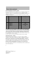
Table of Contents
Severe service conditions
2
Maintenance recommendations
3
Severe duty equipment
4
Air Bag Information
18
All rights reserved. Reproduction by any means, electronic or mechanical
including photocopying, recording or by any information storage and retrieval
system or translation in whole or part is not permitted without written
authorization from Ford Motor Company. Ford may change the contents without
notice and without incurring obligation.
Copyright © 2006 Ford Motor Company
1
2007 Crown Victoria (cro)
Supplement
USA (fus)
Severe service conditions
This brochure is intended to aid the operators of police or fleet vehicles
(used in severe duty, high mileage operations) in understanding the
required maintenance services for such vehicles. It covers maintenance
services for vehicles equipped with Heavy Duty packages. However, other
vehicles operated under the conditions listed below are also considered
“severe service” vehicles and should be serviced and maintained as
prescribed in this brochure. This brochure applies to rear wheel drive
passenger cars only.
CONTACT US
Ford Fleet Hotline - The Ford Fleet Hotline provides police and fleet
customers with direct access to Ford Motor Company for fleet sales or
service information. The hotline number is (800) 34-FLEET.
Ford Fleet Website - Additionally, Ford maintains a website for police
and other fleet vehicles. The Ford Fleet website is located at
www.fleet.ford.com.
2
2007 Crown Victoria (cro)
Supplement
USA (fus)
Maintenance recommendations
Police and fleet vehicles are manufactured with certain heavy-duty parts
that are designed specifically for the varying demands and unique
requirements under which they are operated. Components that are part
of the option packages are listed below and on the following pages with a
brief outline of their major features and their contribution to overall
vehicle performance, handling and usage.
Failure to maintain your vehicle(s) properly may restrict your warranty
coverage, reduce vehicle performance and operational capabilities and
adversely affect driver-passenger safety. The severe duty maintenance
intervals are listed in the “Service Guide.”
The descriptions, specifications and material described in this publication
were in effect at the time the publication was approved for printing.
Ford Motor Company reserves the right to discontinue models at any
time, or change specifications, design or testing procedures without
notice and without incurring obligation.
3
2007 Crown Victoria (cro)
Supplement
USA (fus)
Severe duty equipment
POWERTRAIN OVERSPEED PROTECTION
The powertrain control module (PCM) includes logic to electronically
prevent powertrain overspeed in any transmission selector position.
TRANSMISSION
The police vehicle has a unique high-performance powertrain including
transmission and an aluminum driveshaft, which is designed for
maximum vehicle performance. Due to the nature of this powertrain,
some powertrain noise may be present.
Driving in the overdrive cancel mode for prolonged periods at high
speeds will deteriorate performance and may cause extensive engine
damage.
Crown Victoria police vehicles are designed to operate in the
(Overdrive) gear selector position while in pursuit. Optimum
performance will be obtained in
(Overdrive). Operation in the
overdrive cancel mode should only be used in situations noted in the
“Owner Guide.”
Under no circumstances should the aluminum driveshaft be
replaced with a steel driveshaft. Doing so will adversely affect
vehicle operation which could lead to personal injury.
HOUR METER
Your vehicle may be equipped with an hour meter to indicate how much
time the vehicle is idling in Park or Neutral. The meter is incorporated
with the vehicle odometer. Depressing the odometer-reset button once
will display the trip odometer (miles followed by a ⬙T⬙ for trip
odometer). Depressing the odometer-reset button a second time will
display the hour meter (hours followed by an ⬙h⬙ for hours). The hour
meter only accumulates time when the vehicle is in Park or Neutral.
Displayed time is cumulative for the vehicle. It cannot be reset to zero.
Police/Fleet vehicles often experience long periods of idling, during
which engine oil will continue to break down but mileage is not
accumulated on the odometer.
To assist fleet managers in maintaining proper oil change intervals, the
hour meter will help determine when an oil change is required. For every
hour that the vehicle idles, it has accumulated the equivalent of
approximately 33 miles (53 km) of driving. Using the combination of the
vehicle odometer and hour meter allows the fleet manager to better
determine when the oil needs to be changed.
4
2007 Crown Victoria (cro)
Supplement
USA (fus)
Severe duty equipment
Example: When the odometer has accumulated 2,000 miles (3,219 km)
and the hour meter shows 31 hours, a 3,000 mile (4,828 km) oil change
interval will have been reached: 2,000 road miles + (31 idle hours x 33
miles/idle hour) = 3,023 miles. In metric units this calculation would be
3,219 kilometers + (31 idle hours x 53 km/idle hour) = 4,862 km.
REAR AXLE
Middle Eastern countries only — Because of higher ambient
temperatures, do not drive over 100 mph (160 km/h) for the first 1,000
miles (1,609 km) to allow axle components to wear in.
Lubricant Specifications
Item
Rear Axle
Lubricant
Ford part
name
Motorcraft SAE
75W-140 High
Performance
Synthetic Rear
Axle Lubricant
Ford part
number
F1TZ-19580-B
Ford
specification
WSL-M2C192-A
ELECTRICAL
Battery — Police
The Motorcraft maintenance-free battery normally does not require
additional water during its life. However, for severe service usage or in
high temperature climates, the electrolyte level should be checked at
least every five months or 5,000 miles (8,000 km). If the electrolyte level
is below the level indicator in any cell, add enough pure water to bring
the level up to the indicator. Never add electrolyte (’battery acid”) to the
battery as this could shorten battery life.
Alternator— Police and Long Wheelbase Taxi
The high-output alternator provides 200 amperes of current to support
the high power requirements of modern police equipment. Output at idle
is approximately 130 amperes. Current demand by both the vehicle and
all energized police equipment in excess of this amount during vehicle
idling will place the electrical system into a discharge condition.
Electrical power management systems should be applied if necessary to
avoid discharging the battery.
5
2007 Crown Victoria (cro)
Supplement
USA (fus)
Severe duty equipment
Power Distribution Connector- Police
Power for aftermarket police equipment can be obtained from the Power
Distribution Connector located under the glove compartment. This
connector contains several fused power feeds and inputs available for the
addition of police accessories. The following figure shows the circuits
available for equipment.
Pin
Function
Gauge
Color
1
5A Start
18
Red/Black
2
Vehicle speed signal
18
Gray/Black
3
Battery saver
18
Dark green/Light green
4
20A Battery
14
Light green
5
15A Battery
18
Orange/Light green
6
50A Battery
10
Tan/Yellow
7
20A Run/Acc
14
Pink
8
20A Battery
14
Light Blue/White
9
20A Run/Acc
14
Tan
10 Hazard out
18
Black/Yellow
11 50A Battery
10
Red/White
12 Hazard In
18
Gray/White
The mating connector is provided on the end of the Power Distribution
Connector. The vehicle modifier can either purchase pins for the mating
connector and install them on the wires before they are inserted into the
connector, thereby avoiding any splicing, or purchase an optional power
pigtail for the interface. The power pigtail (P/N 14A411) plugs into the
Power Distribution Connector and provides twelve blunt cut wires ready
for splicing by the vehicle modifier.
See the 2007 Police Interceptor Modifier Guide for more details
Rear Power Point — Police
The Rear Power Point is a battery access port for Police auxiliary
equipment mounted in the trunk. It is capable of supplying 80 amps of
battery power. The Front Power Distribution Box (PDB) contains two
fifty amp fuses, which protects the Power Point. Battery access is via
two studs contained in an enclosure, mounted in the trunk, on the right
side fender support. The terminal with the red wires is the battery
positive, and the terminal with the black wire is the ground. Remove
both fuses in the Front PDB before removing the cover to the rear
power point. Ensure load devices can be turned off, and are switched off
when reinserting fuses.
6
2007 Crown Victoria (cro)
Supplement
USA (fus)
Severe duty equipment
Under no circumstance should the cover be removed without
first pulling the two fuses in the Front Power Distribution Box.
Removing cover without pulling fuses could result in an electrical
hazard, and result in personal injury. Shut off load devices before
inserting fuses.
Headlight Flashers (Wig-wags) - Police
An interfacing connector is provided on the headlight circuit for use of
the headlights as alternating flashers (wig-wags). The connector is
located in front of the radiator. A protective cap is attached to prevent
contaminants from entering the connector when a wig-wag module is not
installed. When installing a headlight flasher (wig-wag) module, remove
the connector and tape it to the wigwag module harness. This will ensure
that the cap is available to be reattached if the wig-wag module is
removed. For additional information, refer to the Crown Victoria
Wiring Diagram Manual.
If your vehicle is equipped with one of the optional Police Interceptor
Equipment Packages, the connector will already be used by the supplied
wig-wag module that comes with the option package.
Note: Use of the wig-wag feature overrides normal operation of the high
beam headlights, including flash-to-pass. However, the low beam
headlights will remain on and unaffected.
HEAVY-DUTY SUSPENSION-POLICE
This option includes certain heavy-duty components that contribute to
the vehicle’s stability and road handling capability under extremes of
operation. The police vehicle has a heavy duty steering gear, extra
control shock absorbers and heavy-duty front and rear stabilizer bars.
COOLERS
Extra oil cooler-Police
It is strongly recommended that auxiliary devices such as lights not be
installed at the grille. Such devices will reduce airflow through the grille
and could potentially impact the cooling system performance.
The 4.6L engine has an engine oil cooler mounted below the radiator fan
to maintain engine oil temperatures.
7
2007 Crown Victoria (cro)
Supplement
USA (fus)
Severe duty equipment
WHEELS/TIRES/BRAKES
Wheel rims-Police
To withstand the demands placed on vehicles driven under heavy-duty
service conditions, Ford Motor Company installs heavy-duty steel wheels.
Tires — Police
Tires (including the spare) are speed-rated radials for police use. Use
only the recommended tire size and speed ratings.
In regions with snow and ice during the winter months, installation of
snow tires may be desirable. Snow tires will usually exhibit a drop in dry
pavement handling, but many show an increase in snow and ice traction.
When snow tires are used, they should be installed on all four wheels,
never on the drive wheels only.
Long term storage
Most high performance tires are made with a nylon overlay.
As such, the following steps should be taken to avoid flatspotting when
the vehicles are not used for a period of time.
• Fleets should store the vehicles with 44 PSI in the tires.
• If the vehicle is stored for periods longer than 30 days, it should be
moved several feet at least once during each 30-day period, so that a
different portion of the tread contacts the ground.
• Tire pressure should be reduced to the recommended pressure shown
on the vehicle certification label before the vehicle is placed back into
service.
Brakes-Police
The police vehicle is equipped with heavy-duty front disc brake pads to
meet the varying demands of different police service for fade resistance
and other performance requirements.
The police vehicle has standard ABS anti-lock brakes and may be
equipped with traction control; refer to the Owner’s Guide for operation
of these systems.
INTERIOR
Heavy-duty seats-Police
The front seat assemblies, including the seat adjustment mechanisms and
supports, are ruggedly designed and ensure working comfort.
8
2007 Crown Victoria (cro)
Supplement
USA (fus)
Severe duty equipment
Seat Belt Extenders
A common complaint from police officers is the difficulty of buckling and
unbuckling the seat belt due to the location of a vehicle equipment
console and/or equipment being worn on the hip, such as a side arm.
The length of the buckle in relation to these other components can make
the buckle difficult to find and make connection of the seat belt
challenging. As a result, some police departments have begun employing
the use of seat belt extenders to make the practice of buckling and
unbuckling of seat belts easier for the driver.
Seat belt extenders should never be worn when the lap strap will not
adjust snugly on the hips and/or when the intersection of the lap belt
and shoulder belt straps (measured along the lap strap) is less than six
(6) inches from an imaginary center line of the occupant’s body.
Do not use extensions to change the fit of the shoulder belt
across the torso.
Calibrated speedometer-Police
Deviations from true road speeds are minimized by a calibrated
speedometer head which gives both miles-per-hour (0–140 mph) and
kilometer-per-hour (0–222 km/h) readings. The speedometer head
assembly accuracy is ⫾2 mph ( ⫾3 km/h) over the entire range (at 21°C
[70°F]). The “certified calibration” applies to the head assembly only and
does not apply to the indicated speed of the system, which is affected by
variations in vehicle loading, tire inflation pressures, tire rolling radii and
driveline ratios.
Mobile communication systems
The Federal Communications Commission regulates the use of mobile
communication systems (such as two-way radios, telephones and theft
alarms) that are equipped with radio transmitters. If you install this
equipment in your vehicle, you should comply with those rules and a
qualified technician should install the equipment. Ford Motor Company
vehicles are in compliance with FCC regulations (CFR 47 Part 15) and
SAE J551d for radiated electromagnetic emissions.
Mobile communication systems may harm the operation of your vehicle,
particularly if they are not properly designed for automotive use or not
properly installed. For example, when operated, such systems may cause
the engine to stumble or stall and may affect 4R70W transmission
operation. In addition, such systems may themselves be damaged or their
9
2007 Crown Victoria (cro)
Supplement
USA (fus)
Severe duty equipment
operation affected by operating your vehicle. (Citizen band [CB]
transceivers, garage door openers and other transmitters whose power
output is 5 watts or less will not ordinarily affect your vehicle’s
operation.)
Because we have no control over the installation, design or manufacture
of such systems, Ford cannot assume responsibility for any adverse
effects or damage that may result if you use this equipment.
Malfunction of aftermarket electronic equipment should be resolved by
the equipment manufacturer.
Aftermarket equipment installation
Ford has developed a Police Interceptor Modifier Guide to assist the
vehicle modifier in safely installing police equipment into the vehicle.
The guide provides detailed information on the location of key vehicle
components that must be untouched and warnings for other areas where
caution must be exercised. The Modifier Guide is available for
downloading, free of charge, from www.fleet.ford.com.
When installing aftermarket equipment, avoid using fasteners that are too
long for the application or are in an area which might damage vehicle
components, including wiring, brake lines, fuel tank and lines, powertrain
components, exhaust system and suspension.
Also, do not make electrical connections to vehicle electrical systems not
specifically designed for aftermarket equipment installations. Refer to the
“Electrical and Vacuum Troubleshooting Manual” for electrical system
information.
Do not install any components into the Powertrain Control Module
(PCM) or PCM harness. Connecting into this system may affect engine
and transmission operation.
As an example: connection of aftermarket electrical equipment into the
brake light circuit or any other circuit which is connected to the PCM,
anti-lock brake computer, air bag system or any other vehicle system
which will cause vehicle malfunction.
Contact during a crash with aftermarket equipment in a vehicle
can result in a personal injury.
Installation of prisoner barriers may increase the risk of injury to
front seat occupants if the vehicle is impacted from the rear at
high speeds. This risk should be balanced, by the law enforcement
agency, against the risk of injury to the Officer associated with prisoner
transport.
10
2007 Crown Victoria (cro)
Supplement
USA (fus)
Severe duty equipment
Trunk Pack姟 and trunk loading
Ford recommends that police equipment be both secured and
laterally aligned. Hard, stiff or sharp objects, especially when not
secured or properly located, pose a risk to the fuel tank and back seat
occupants in the event of a high speed rear impact. After-market
organizers that do not adequately deform in rear-impacts can
themselves become injury-producing objects. When locating, securing
and mounting police equipment, please review the ⬙Trunk Equipment
Mounting Guide,⬙ available on the www.cvpi.com website, which
provides recommended fastener mounting types and locations.
Following the trunk packing recommendations, also on the
www.fleet.ford.com website, is the most meaningful method of
reducing risk. If your department practice is inconsistent with the
trunk packing recommendations, then Ford suggests that you consider
purchasing an optional drop-in Trunk Pack娂 to further reduce the risk
of injury resulting from police equipment pushing forward into the
back seat and/or fuel tank in the event of a high-speed rear impact.
The Trunk Pack娂 provides more flexibility to officers transporting
police equipment than the truck packing recommendations.
To improve trunk packing by police agencies, Ford has made the
following items available:
• Trunk Pack娂 – a drop-in box with a tough plastic shell made of High
Density Polyethylene (HDPE). It both aligns police equipment laterally
in the trunk and utilizes a puncture resistant lining on the forward
side of the box to reduce the risk of police equipment penetrating into
the fuel tank and/or back seat in high-speed rear impacts.
• Trunk Equipment Mounting Guide – an outline pattern with
recommended fastener mounting locations in the trunk. The guide can
be found in the Police Interceptor Modifier Guide and on the Internet
at www.fleet.ford.com.
• Trunk Packing Considerations – the following guidelines are offered to
reduce the risk of unique police equipment items pushing through the
fuel tank and/or back seat (see our www.fleet.ford.com website for
more details).
11
2007 Crown Victoria (cro)
Supplement
USA (fus)
Severe duty equipment
Trunk Packing Considerations
A slogan has been developed to increase police agency awareness of the
importance of trunk packing.
L-Lateral
O-Orientation
A-and
D-Direction
’LOAD SAFE’
S-Soft
A-and
F-Fixed
E-Equipment
Equipment Categories and Placement
It is recognized that a wide variety of equipment is carried in the trunks
of police vehicles as noted above. This section addresses the inherent
risks of various types of equipment in the event of a high-speed rear
impact.
This information is divided into three categories:
• Carrying Not Recommended
• Carry With Caution
• Low Risk Items
Carrying not recommended – The following items have been
observed in police vehicles and should not be transported in a
vehicle trunk – containers with gasoline, loose ammunition, loose flares,
loose fire extinguisher(s), loose 4-point lug wrench, loose crowbars, loose
axes and other loose equipment with potential puncture capability in
high speed rear end collisions.
Gasoline should not be stored in the trunk at any time,
regardless of container.
Carry with caution – These items will require special packing or
mounting consideration and possibly use of the Trunk Pack娂 as an
additional level of safety. Examples include (with proposed orientation):
fire extinguisher (fixed), lug wrench 4 point (fixed - vertical), rolotape
measuring wheel (fixed - vertical), safety flares (lateral orientation – in a
container), Stop Stick (lateral - mount on deck lid inner panel), shovel
(lateral - place at rear of trunk), shotgun and rifle (lateral - store in
case), baton (lateral - place at rear of trunk), ammunition (container).
Flares should be placed in a protective storage container (preferably soft
sided plastic). Flares with spikes attached should be laterally oriented in
the trunk area.
12
2007 Crown Victoria (cro)
Supplement
USA (fus)
Severe duty equipment
1. Spare Tire Special Considerations – The safest location for the
spare tire, jack and lug wrench is the production location on the forward
package shelf above the rear axle. If unable to mount there, the next
safest location for the spare tire is mounted vertically inside the Trunk
Pack娂 using the J-bolt attachment device provided with the Trunk
Pack娂. The jack and lug wrench should be stored in the rearward
compartment of the Trunk Pack娂.
2. Electronic Equipment – The safest location for the electronic
equipment is on the trunk forward package shelf. Some equipment can
be mounted in the side shelf areas, but it must not protrude into the fuel
tank area in a crash (noted in Trunk Equipment Mounting Guide). The
optional Complete Police Prep Package is available to facilitate packaging
of electronic components with a sliding tray for the forward package
shelf and side compartments in the right and left shelf area. All
equipment should be located and mounted using the ⬙Trunk Equipment
Mounting Guide⬙ for proper positioning of fasteners. This guide can be
accessed on the www.fleet.ford.com website. The sliding tray can also be
used, depending on size, to properly store parts with rigid and sharp
edges.
3. Ammunition – The safest location for ammunition is the forward
package shelf and on the side shelves. It is recommended that a plastic
storage container be utilized and mounted using the ⬙Trunk Mounting
Equipment Guide⬙ for proper fastener locations. It is also recommended
that ammunition remain in the purchased container and be placed in a
safe storage container .
Low risk items – These items are soft in feel and pose a low risk of
trunk wall, rear seat area, and fuel tank puncture. Examples are: a soft
camera case, biohazard kit in plastic boxes, gloves, safety rope, tow
strap, traffic cones & sleeves, rain gear, riot gear (soft), emergency
blankets, bullet resistant vest, tie straps, cloth tape, garment bags, first
responder kit, Res-Q-Flo mask (placed in garment bag), fuses (plastic
container), briefcase, notebooks, spray bottles, helmet, and jumper
cables. It is not essential but recommended that the Trunk Pack娂 can be
considered for organization of low risk items, especially if mixed with
“Carry With Caution” items.
13
2007 Crown Victoria (cro)
Supplement
USA (fus)
Severe duty equipment
BODY
Fire Suppression System (if equipped)
Your vehicle may be equipped with an optional fire suppression system.
The fire suppression system is designed to help reduce the risk of injury
in high-speed rear impacts. The fire suppression system deploys
chemicals designed to slow the spread of fire or potentially extinguish a
fire, thereby providing more time for occupants to escape from a crashed
vehicle.
The Fire Suppression System is mounted beneath the vehicle and
attached to the frame above and forward of the fuel tank and rear axle.
The Fire System Control Module is mounted inside the passenger
compartment centered underneath the rear seat cushion. The system is
designed to deploy automatically after sensing a high-speed/high-energy
rear end impact.
There is a covered manual activation switch mounted in a console on the
headliner between the visors that can be used by vehicle occupants to
manually deploy the system. The fire suppression system can be
manually deployed any time the vehicle is in a Key ON or Engine ON
mode by pushing the button underneath the cover. The button can be
accessed three ways:
1. Pushing on the cover will release the cover latch, allowing the door to
swing open and expose the button;
2. The cover can be pulled open;
3. A firm strike on the cover (about 20 lbs of force) will deploy the
system any time the vehicle is in a Key ON or Engine ON mode.
In the event of a manual deployment, nozzles will deploy to near ground
level and the underbody of the vehicle will be covered with suppressant
fluid. The suppressant contains no hazardous materials (but may cause
minor skin or eye irritation) and can be readily cleaned up by flushing
the underbody with water (or soap and water). Manual deployment
should have no adverse affect on vehicle handling; however, caution
should be exercised in moving the vehicle as ground clearance will be
compromised by the deployed nozzles. Because of reduced ground
clearance, the vehicle should not be driven through an automatic car
wash with nozzles in the deployed condition.
The fire suppression system is a single use system—all major
components will have to be replaced in the event of a manual
deployment.
14
2007 Crown Victoria (cro)
Supplement
USA (fus)
Severe duty equipment
Figure A
The approved ISO symbol for Fire Suppression is shown in Figure A.
This symbol is printed on the manual activation switch and on the
diagnostic telltale on the instrument cluster.
The system automatically performs a diagnostic check self check and
momentarily lights the cluster lamp at Key ON. If the diagnostic lamp
stays on refer to the appropriate sections of the Ford service manual for
further diagnostic and service procedures.
The system is active any time the vehicle is in a Key ON or Engine ON
mode following the diagnostic check.
The system has been designed and tested to withstand a 75 mph 50%
off-set rear impact by Taurus-sized vehicle. However, in some crashes,
including very high-energy crashes, the fire suppression system could be
so damaged by the crash forces that it cannot deploy. Like any vehicle
component, the Fire Suppression System cannot withstand any and all
crashes. No vehicle can eliminate the risk of fires. You should not
consider the vehicle ⬙fire proof⬙ because it is equipped with a Fire
Suppression System.
Ballistic Door Panels
Your vehicle may be equipped with ballistic door panels on one or both
of the front doors. Doors equipped with a ballistic panel are marked with
a sticker on the interior door trim panel above the door handle indicating
⬙BALLISTIC PANEL.⬙ Otherwise, doors with ballistic panels are visually
indistinguishable from standard doors. The ballistic panels are designed
to act as a shield for the officer at the scene of an altercation.
The door panels meet National Institute of Justice (NIJ) Level III-A
protection requirements. NIJ is the research, development, and
evaluation agency within the U. S. Department of Justice. The panels
have been tested and certified by H.P. White, an approved testing agency
of the U. S. Department of Justice, in accordance with NIJ Standard
0108.01, MIL-STD-662F, and Los Angeles Police Department (LAPD)
Standard MTD 05-01E.
15
2007 Crown Victoria (cro)
Supplement
USA (fus)
Severe duty equipment
Manufactured by combining ballistic grade ceramic and DuPont娂
KEVLAR威, this composite ballistic door panel has been extensively
tested with the rounds called out in the above-referenced specifications.
The panels have been subjected to standard Ford Motor Company
vehicle testing, including long-term durability, key life, and crash testing.
Important: In the interest of officer safety, detailed panel performance
specifications are not shown here. The specifications can be dangerous in
the hands of criminals. Contact 1-800-34-FLEET for panel performance
specifications.
As with body armor, protection provided by the ballistic panel is
limited. Certain rounds or combinations of rounds may penetrate
the panel and cause serious injury or death.
Use of Ballistic Door Panels
It is critical that officers understand where the panel is located inside the
door in order to achieve optimal ballistic protection. Figure B illustrates
the location of the ballistic door panel and the mechanical anchor points
inside the door.
The door panels are designed to provide a shield for the officer at the
scene of an altercation. Any protection afforded the officer while
patrolling inside the vehicle is incidental.
The ballistic ceramic faces the outside of the door. It is imperative
that the officer using the panel as a ballistic shield has the
exterior of the door facing the threat. In other words, the officer
should be positioned behind the interior portion of the door for
ballistic protection.
Figure B
The above illustration from the exterior of a left front door. The two
brackets on the top illustrate the top anchor points. They are covered by
16
2007 Crown Victoria (cro)
Supplement
USA (fus)
Severe duty equipment
the belt line molding and are not visible from outside or inside the
vehicle. The panels are also attached to the side impact beams as shown
in the illustration. The brackets on the bottom simply hold the panel
halves together to assist in ballistic performance.
Removing the Panels
It is important that these panels be removed from the vehicle after the
vehicle has been impacted on the protected door, the door has been
shot, or the vehicle is being removed from active duty. For details on
panel removal, refer to Crown Victoria Shop Manual. After removal,
panels can be shipped to the address below for proper disposition and
recycling of materials:
Ceramic Protection Corporation
3905 32nd Street N.E.
Calgary, AB T1Y 7C1
Canada
When the panels are removed, the ⬙Ballistic Panel⬙ label affixed to the
door trim panel must also be removed.
1
DuPont娂 and KEVLAR威 are trademarks or registered trademarks of
DuPont娂 or its affiliates.
17
2007 Crown Victoria (cro)
Supplement
USA (fus)
Air Bag Information
AIR BAGS
Dual driver/passenger air bags and side air bags (if equipped) affect the
way police equipment can be mounted in police vehicles.
Any surfaces that could come into contact with an air bag, once it has
deployed, must not damage the air bag or alter its deployment path.
Once the air bag has fully deployed, any peripheral equipment surfaces
that could come into contact with the air bag (such as when the air bag
deflates with the loading of an occupant) must not damage the air bag or
alter its deployment path. Sharp edges, corners or protrusions could
damage the nylon air bag material and reduce the effectiveness of the air
bag.
Do not place objects or mount equipment in front of the air bag
module cover or in front of the seat areas that may come in
contact with a deploying air bag. Failure to follow this instruction could
result in personal injury.
Dash, tunnel or console-mounted equipment should not be
placed outside of the specified zone. Failure to follow this
instruction could result in personal injury.
Do not mount equipment between the side of front seat to the
door trim to block deployment of the side air bag. Failure to
follow this instruction could result in personal injury.
Some approximate dimensions for air bags, at full inflation, are provided
in Figures 1 through 5. These dimensions are somewhat flexible and
represent “free form” deployments without the loading of occupants. The
shaded areas in Figures 6 through 8 represent available police equipment
mounting zones. These zones are shown for police vehicles equipped
with standard bucket seats. While bench seats are optional and still
appropriate for vehicles with certain limited police equipment
requirements, the standard bucket seats are recommended for vehicles
that require maximum available space for police equipment mounting.
The zone dimensions provided in Figures 6 through 8 are approximate
and will vary with the loading of occupants in the seats.
All air bag and equipment mounting zone dimensions are approximate
due to different air bag deployment characteristics.
No equipment will mount between the side of the front seat and the
door trim to block deployment of the side air bag.
18
2007 Crown Victoria (cro)
Supplement
USA (fus)
Air Bag Information
2
1
50
40
80
60 70
100
80
120
140
100
160
40
20
90
60
30
180
20
10
200
P RND21
110
120
L
3
Figure 1
1. 9.5 inches (240 mm) from center of air bag door
2. 15.7 inches (400 mm) from center of air bag door
3. 28.5 inches (725 mm)
No objects should be placed between the air bags due to air bag
variability.
19
2007 Crown Victoria (cro)
Supplement
USA (fus)
Air Bag Information
1
Figure 2
1. 30.5 inches (775 mm). Cross section through center of vehicle
(passenger side shown)
20
2007 Crown Victoria (cro)
Supplement
USA (fus)
Air Bag Information
Figure 3
1. 23.6 inches (600 mm). Front passenger compartment
2. 17 inches (430 mm). Front driver
21
2007 Crown Victoria (cro)
Supplement
USA (fus)
Air Bag Information
Figure 4 (if equipped)
1. 8 inches (200 mm). From out board side of seat
2. 15 inches (380 mm). Forward of seat back
Figure 5 (if equipped)
3. 27.5 inches (700 mm). Up from SAB module
22
2007 Crown Victoria (cro)
Supplement
USA (fus)
Air Bag Information
1
2
50
40
80
60 70
100
80
120
140
90
60
30
100
160
40
20
180
20
10
200
P RND21
110
120
L
4
3
Figure 6
1. Area on top of instrument panel. Equipment must not interfere
with driver visibility.
2. The air bag door must be kept clear for deployment of air bag
3. Area in front of center console from bottom of ashtray to top of
instrument panel (see Figure 2 for dimensions)
4. 11 inches (279 mm) width horizontally centered on ashtray door.
23
2007 Crown Victoria (cro)
Supplement
USA (fus)
Air Bag Information
3
2
1
10
7
6
9
8
5
4
Figure 7
1. Area on top of instrument panel
2. Area in front of center console from tunnel up to instrument panel
3. Prisoner screen
4. 10 inches (254 mm)
5. Area on tunnel between seats
6. Height: 8.5 inches (216 mm)
7. 12 inches (305 mm)
8. Area on tunnel beneath center console
9. Tunnel
10. Depth: 1.5 inches (38 mm)
24
2007 Crown Victoria (cro)
Supplement
USA (fus)
Air Bag Information
1
4
3
2
Figure 8
1. Area on top of instrument panel. Equipment must not interfere
with driver visibility.
2. Area on tunnel between seats
3. 9 inches (229 mm)
4. 12 inches (305 mm)
IMPORTANT AIR BAG DO’S AND DON’TS
Do not attempt to tamper with, disconnect or deactivate the air
bag system.
Tampering with an air bag system could cause the bag to inflate or
become inoperative. The air bag system should not be disconnected or
deactivated.
Do not mount or place any objects in the deployment path of an
air bag.
25
2007 Crown Victoria (cro)
Supplement
USA (fus)
Air Bag Information
Air bags must be allowed to fully deploy without restriction. The
deployment of air bags is not compatible with any configuration of police
equipment mounting that places objects in the air bag deployment path.
Equipment mounted or placed in the deployment path area of an air bag
will reduce the effectiveness of the air bag, damage the air bag and
potentially damage or dislodge the equipment. Further such items could
become projectiles in the event of an air bag deployment.
Always use safety belts with the air bag supplemental restraint
system.
There are four very important reasons to always use seat belts with the
air bag system. Safety belts:
• help restrain the occupant to increase the effectiveness of the air bag
when it inflates.
• reduce the risk of injury in rollover, side or rear impact accidents for
which air bags are not designed to inflate.
• reduce the risk of injury in frontal collisions that are not severe
enough to activate the air bag.
• reduce the risk of passengers being thrown from the vehicle.
SOME COMMON POLICE QUESTIONS AND ANSWERS ABOUT AIR
BAGS
Will there be any way to special order police vehicles without the
air bag systems?
No. Based on the federal law (FMVSS #208), after August 31, 1993, the
Original Equipment Manufacturers (OEMs) will not be able to sell
passenger cars that do not contain passive restraint systems.
Can the installation of push bumpers on the front end of the
vehicle affect the deployment of an air bag?
Different push bumper designs may each have different deformation
characteristics in a crash situation that may or may not affect the
deployment of air bags. Without the benefit of crash tests on vehicles
equipped with push bumpers (there are a number of different styles
available), it is Ford’s opinion that installation of some push bumpers
could affect the timing of the air bag deployment. Use of a push bumper
that mounts solely to the vehicles bumper should not have a significant
effect upon air bag deployment.
26
2007 Crown Victoria (cro)
Supplement
USA (fus)
Air Bag Information
Is there a problem with transporting a front seat passenger who
has their hands restrained behind their body?
This is not a normal riding position for an occupant. The effectiveness of
the passenger air bag will depend, in part, upon the occupant’s seated
position. It is recommended that the seat should be adjusted as far
rearward as possible for this situation, and that the occupant sit as
upright as possible and be properly safety belted. It is recommended that
such passengers be properly restrained in the rear seat if at all possible.
Can conditions encountered in aggressive pursuit driving
situations (e.g., high speed braking, uneven road surfaces) cause
inadvertent inflation of an air bag that might result in loss of
vehicle control?
Air bags are designed to deploy in moderate to major frontal crashes
based on the detection of sudden deceleration by sensors in the vehicle.
The air bag system is designed to activate in a frontal collision equivalent
to hitting a solid barrier (such as a wall) at about 14 mph (23 km/h) or
more, or, roughly speaking, a parked car of similar size at 28 mph (45
km/h ) or more. When activated, the air bag fully deploys in about 50
milliseconds (1/20th of a second). Following inflation, the air bag begins
to vent almost immediately and is deflated in about one second.
27
2007 Crown Victoria (cro)
Supplement
USA (fus)
28
29
30
31
32