1
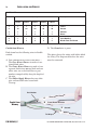
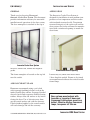
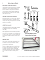
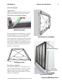
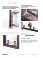
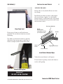
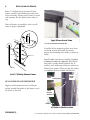
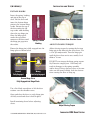
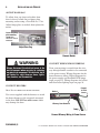
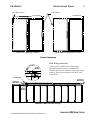
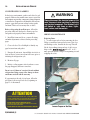
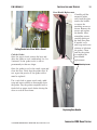
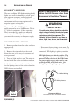
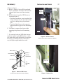
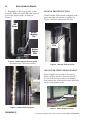
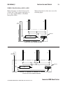
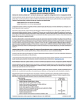
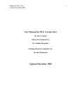
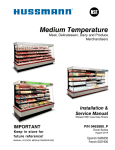
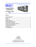
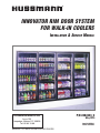
®
INNOVATOR RIM DOOR SYSTEM
FOR WALK-IN COOLERS
INSTALLATION & SERVICE MANUAL
HUSSMANN/AMERICAN
Arroz 155
Iztapalapa, México D.F. 09820
Tel: 85 03 19 00
MANUAL- I/O WALK-IN RIM COOLER DOORS
P/N 2402443_C
May 2015
Spanish 2402623
French 0527089
P/N 2402443_C
I NNOVATOR C OOLER D OOR S YSTEM
(C OMPOSITE ) I NSTALLATION AND S ERVICE
iii
Table of Contents
Parts List . . . . . . . . . . . . . . . . . . . . . . . . . . . . . . . . . . iv
Connect Heaters . . . . . . . . . . . . . . . . . . . . . . . . . . . . . 8
General . . . . . . . . . . . . . . . . . . . . . . . . . . . . . . . . . . . . 1
Always*Clear™ Glass . . . . . . . . . . . . . . . . . . . . . . . . 1
Connect Wiring from Wireway . . . . . . . . . . . . . . . . . 8
Heater Harnesses . . . . . . . . . . . . . . . . . . . . . . . . . 9
Field Wiring Connection . . . . . . . . . . . . . . . . . . 9
Wiring Diagrams . . . . . . . . . . . . . . . . . . . . . . . . 10
Electrical Specifications . . . . . . . . . . . . . . . . . . . . . . . 2
Conditioning Gasket . . . . . . . . . . . . . . . . . . . . . . . . 12
Specifications for Opening . . . . . . . . . . . . . . . . . . . . . 2
Service and Maintenance . . . . . . . . . . . . . . . . . . . . . 12
Shipping Damage . . . . . . . . . . . . . . . . . . . . . . . . . . . . 2
Replacing Doors . . . . . . . . . . . . . . . . . . . . . . . . 12
Replacing Door Hinge Spring . . . . . . . . . . . . . 13
Replacing Magnetic Gasket . . . . . . . . . . . . . . . 14
Restoring Gasket Seal . . . . . . . . . . . . . . . . . . . . 15
Door Handle Replacement . . . . . . . . . . . . . . . . 17
EcoShine™ LED Fixture Replacement . . . . . . 16
EcoShine™ LED Power Supply Replacement . . 18
EcoShine™ LED Wiring Diagrams . . . . . . . . . 19
Fluorescent Lamp Replacement (Center Mullion) 22
Fluorescent Lamp Replacement (End Mullion) . . 24
Ballast Replacement . . . . . . . . . . . . . . . . . . . 24
Frame Heater Replacement . . . . . . . . . . . . . . . 25
Fluorescent Lamp Wiring Diagrams . . . . . . . . . 26
Application . . . . . . . . . . . . . . . . . . . . . . . . . . . . . . . . . 1
Preparation . . . . . . . . . . . . . . . . . . . . . . . . . . . . . . . . . 2
Install Frame . . . . . . . . . . . . . . . . . . . . . . . . . . . . . . . 3
Apply Sealant . . . . . . . . . . . . . . . . . . . . . . . . . . . 3
Check Frame and Opening for Square . . . . . . . . 3
Place Frame in Opening . . . . . . . . . . . . . . . . . . . 3
Fasten Frame to Cooler Wall . . . . . . . . . . . . . . . 4
Joining Frames . . . . . . . . . . . . . . . . . . . . . . . . . . . . . . 5
Seal Inside Frame Perimeter . . . . . . . . . . . . . . . . . . . 6
Attach Door Handles . . . . . . . . . . . . . . . . . . . . . . . . . 6
Install Doors . . . . . . . . . . . . . . . . . . . . . . . . . . . . . . . . 7
Adjust Closing Torque . . . . . . . . . . . . . . . . . . . . . . . . 7
Adjust Door Sag
............................8
Replacement Parts Chart . . . . . . . . . . . . . . . . . . . . . 22
REVISION C REMOVED IR UPDATED FOR WC
REVIS ION B
1. Added EcoShine LED, Pages 16 through 21.
2. Added LED parts list, Pages 31
IMPORTANT
KEEP IN STORE FOR FUTURE REFERENCE
Quality that sets industry standards.
Hussmann Corporation
Corporate Headquarters
12999 St. Charles Rock Road • Bridgeton, MO 63044 U.S.A. • (314) 291-2000 • FAX (314) 298-4767
HUSSMANN/AMERICAN • Arroz 155 • Iztapalapa, México D.F. 09820 • Tel: 85 03 19 00
U.S. & Canada 1-800-922-1919 • Mexico 1-800-890-2900
©2015 Hussmann Corporation
I NSTALLATION
iv
AND
S ERVICE
PARTS LIST
Item
Quantity
1.
2.
3.
4.
Joining
5.
6.
Description
1 DOOR
2 DOOR
3 DOOR
4 DOOR
5 DOOR
1
10
1
1
1
20
1
2
1
30
1
3
1
40
1
4
1
50
1
5
Frame
Screws
Silicone
Doors
1
5
1
5
1
5
1
5
1
5
Joint Molding
Binder Post and Screw
D. The Ground wire is green.
Conduit from Wireway
Each frame has the following wires in flexible
conduit:
This photo shows the wiring with labels added
for clarity. The diagram shows how the wires
must be connected.
A. LOW TEMPERATURE APPLICATION ONLY —
The Door Heater Harness is made of two
joined black wires.
B. The Frame Heater Harness is made of two
separate black wires OR one black and one
white wire; one or both will have a part
number stamped visibly along the length of
the wire.
C. The Ballast Supply Harness has one white
wire and one black wire bound with
Tiewrap.
Part Number
A
Conduit from
Wireway
B
ss
ter Harne
Door Hea
Frame Heater Harness
D Ground
Tie-Wrap
P/N 2402443_C
C Balla
st Su
pply Ha
rness
HUSSMANN CORPORATION • BRIDGETON, MO, 63044-2483 U.S.A.
P/N 2402443_C
I NSTALLATION
AND
S ERVICE
1
GENERAL
APPLICATION
Thank you for choosing Hussmann’s
Innovator Cooler Door System. This document
provides information necessary for successful
installation and operation of the door system.
The door nameplate is attached to the top of
The Innovator Cooler Door System is
designed for installation in new medium temperature or low temperature walk-in coolers
with insulated structural walls. To maintain
structural integrity of the cooler wall and the
door system. the cooler wall must be manufactured with a reinforced opening to match the
door frame.
Innovator Cooler Door System
the door, handle side, behind the magnetic
gasket.
The frame nameplate is located on the top left
near the switch.
Standard Reinforced Opening
Frames may be joined when more than a
5 door length is needed. Frames to be joined
are manufactured without the vertical outside
frame flange.
ALWAYS*CLEAR™ GLASS
Hussmann recommends using a soft cloth
with isopropyl (rubbing) alcohol to clean the
inside (coated) glass surface. Isopropyl alcohol
does not freeze and evaporates without leaving
residue. Always allow the surface to dry before
closing the door. Use of abrasives may damage the coated surface and void the warranty.
Labels (stickers) applied to the coated surface
will cause damage and oid the warranty.
HUSSMANN CORPORATION • BRIDGETON, MO, 63044-2483 U.S.A.
Door systems manufactured with
Innovator or Innovator II doors and
fluorescent lighting have an anti-arc
ballast. When re-starting fluorescent
lamps, turn power off then on.
I NNOVATOR RIM D OOR S YSTEM
2
I NSTALLATION
AND
S ERVICE
ELECTRICAL SPECIFICATIONS
Appropriate electrical power must be available
for the door system, including lighting and
heaters. Check the nameplate for minimum
circuit ampacity and maximum overcurrent
protection device. Always follow NEC guidelines and local codes.
Allen Wrenches
Drill
Screwdrivers
Flat Head Phillips Torx Plus #27
SPECIFICATIONS FOR OPENING
Each door frame is 1 to 5 doors wide. Several
standard frame heights are available. Always
compare the wall opening dimensions with the
frames to be installed.
Open End Adjustable
Wrench
Wrench
Tape Measure
Pliers
Rubber Mallet
SHIPPING DAMAGE
All equipment should be thoroughly examined
for shipping damage before and during
unloading.
Plumb Line
4 ft. Level
This equipment has been carefully inspected at
our factory. Any claim for loss or damage must
be made to the carrier. The carrier will provide
any necessary inspection reports and/or claim
forms.
Typical Tools Needed to Install
Innovator Cooler Door System
PREPARATION
Clear an area outside the wall opening to lay
the frame flat and work around it. Gather
tools needed for installation.
Doors are shipped separately from the frame.
Set doors aside until frame is installed. Lay
the frame face down. Remove all packing
materials, packaged parts and tape. Take care
not to scratch or otherwise damage frame
face.
P/N 2402443_C
Unpack Frame and Lay Face Down
U.S. & Canada 1-800-922-1919 • Mexico 1-800-522-1900 • WWW.HUSSMANN.COM
I NSTALLATION
P/N 2402443_C
AND
S ERVICE
3
INSTALL FRAME
Apply Sealant
Apply field-supplied silicone sealant between
edge of gasket and outside edge of frame.
Check Frame and Opening for Square
Apply Silicone Sealant
Verify the frame is not racked (out of square)
by measuring from one corner diagonally to
the other. The measurements must be the
same. Verify that the opening is large enough
for the frame. Use a long level (4 ft (1220 mm)
or more) to determine if the opening is level
side to side. If shims are needed, they must be
used under the frame at the bottom of the
opening, or at the sides.
Verify Square and Level Opening
Do Not Damage Wiring
Must Be Equal
Verify Square Frame
Place Frame in Opening
Lift frame by mullions to avoid gaskets and
sealant. Position bottom of frame in opening
and then tilt top of frame toward opening.
Take care that wiring from wireway at top of
frame is not damaged.
Add Shims
When Needed
Place Frame in Opening
HUSSMANN CORPORATION • BRIDGETON, MO, 63044-2483 U.S.A.
I NNOVATOR RIM D OOR S YSTEM
4
I NSTALLATION
AND
S ERVICE
Use the level to ensure the frame is plumb
within the opening. Use shims as needed below
and to the side to keep the frame level.
Fasten Frame to Cooler Wall
Use screws provided to fasten the bottom
frame to the wall.
Insert Screw
Use the Level
Once the frame is properly positioned, large
clamps should be used to hold frame in position.
Fasten the Frame Bottom
Verify frame is still square.
Fasten side frame to wall with screws provided. Use shims as necessary. Do not distort
frame by excessive tightening.
Clamp the Frame
P/N 2402443_C
U.S. & Canada 1-800-922-1919 • Mexico 1-800-522-1900 • WWW.HUSSMANN.COM
P/N 2402443_C
I NSTALLATION
AND
S ERVICE
5
JOINING FRAMES
Frame sides to be joined will have no front
face flange
Install the first frame as above, and prepare
the second frame. Apply 1 in. wide gasket
between wipes of each frame side to be joined.
Lift the second frame into position and fasten
the bottom as above.
End Lamp Reflector
Keep Frame Level
Fasten top of frame to wall with screws
provided. Do not distort frame by excessive
tightening.
NOTE:
Frame Shown
Face Down on Floor
(cut-away for clarity
Gasket
Use shims at each screw location to prevent
distortion. Once screws are in, verify top of
frame is straight and level from side to side.
Top of
Frame
Right Side of Frame
Front of Frame
Install Gasket Between Wipes
Verify the second frame is still square.
If last frame in opening, fasten side frame to
cooler wall opening.
Fasten Frame Top Last
I M P O R TA N T !
DO NOT OVE R-T IGHT EN
HUSSMANN CORPORATION • BRIDGETON, MO, 63044-2483 U.S.A.
I NNOVATOR RIM D OOR S YSTEM
I NSTALLATION
6
AND
S ERVICE
Insert ‘J’ molding between frames. Fasten
frames together with binding post and screw
in five locations. Fasten top of frame to cooler
wall opening. Do not distort frame sides or
top.
Once all frames are installed, verify overall
frame is square and plumb.
Apply Silicone Around Frame
ATTACH DOOR HANDLES
Binder Screw
Binder Post
Carefully lift the magnetic gasket away from
the frame nearest the handle location to
expose the mounting screw holes as shown in
below.
Binder
Screw
Binder Post
Install handle and screws carefully (if gasket
is damaged, it must be replaced). After installing screws, gasket should again lie flat. If
needed, use a mild soap and water solution to
lubricate the gasket. Clean and dry the gasket
to complete the door handle installation.
‘J’ Molding
Install ‘J’ Molding Between Frames
Door
Glass
Inside
Door
SEAL INSIDE FRAME PERIMETER
Apply a small continuous bead of silicone
sealant around the inside of the frame to seal
the frame to the wall.
Door
Handle
Screws
Gasket
Lift Gasket at Handle Location
P/N 2402443_C
U.S. & Canada 1-800-922-1919 • Mexico 1-800-522-1900 • WWW.HUSSMANN.COM
I NSTALLATION
P/N 2402443_C
AND
S ERVICE
7
INSTALL DOORS
Insert the spring, bushing
and pin in the top of
door. Lift the door and
insert the bottom hinge
pin into the bottom hinge
socket. Rotate the top of
the door under the the
top socket while holding
down the top hinge pin.
Once the hinge pin is
under the top socket,
maneuver the door until
the hinge pin pops into
the socket.
Lift Door Retainer Over Shoulder Screw
Spring, Pin and
Bushing
Ensure the hinge pin is fully engaged into the
hinge plate as shown below.
Correct
Fully Engaged
Wrong
Not Fully Engaged
ADJUST CLOSING TORQUE
Adjust closing torque by turning the bottom
hinge pin in the direction the door closes. Use
a 1/2 in. (13 mm) wrench. Turn the hinge pin
until the door closes on its own, usually 3 to 4
clicks or 3/4 turn.
DO NOT over-torque the hinge spring assembly. Excessive torque (over 1 full turn) will
result in damage to the spring assembly
and/or door. If door does not close on its own
after one full turn (5 clicks), look for obstructions causing the door to hang up.
Ensure Hinge Pin is
Fully Engaged into Hinge PLate
Use a flat blade screwdriver to lift the door
retainer over the shoulder screw.
Open and close the door to verify hinge pins
are fully seated and door is held in place.
Install remaining doors before adjusting
doors.
Adjust Closing Torque
HUSSMANN CORPORATION • BRIDGETON, MO, 63044-2483 U.S.A.
I NNOVATOR RIM D OOR S YSTEM
8
I NSTALLATION
AND
S ERVICE
ADJUST DOOR SAG
To adjust door sag (saw-tooth effect from
door to door), loosen the two hinge plate
mounting screws using a Torx Plus no. 27 bit.
Adjust hinge plate as needed, then tighten the
screws.
Receptacle
Loosen both hinge
plate mounting
screws (door
Plug
Install
Screws
removed for clarity of
illustration).
Adjust Door Sag
Connect Heater
A
WARNING
CONNECT WIRING FROM WIREWAY
Always disconnect the electrical power at the
main disconnect when servicing or replacing
any electrical component. This includes, but is
not limited to, such items as doors, lights,
fans, heaters, and thermostats.
Door system wiring is routed from the wireway through flexible conduit to be connected
to the power source. Wiring diagrams for the
heater harnesses follow. Wiring diagrams for
the power supply and EcoShine LED lamps
begin on page 19. Wiring diagrams for ballast
and fluorescent lighting begin on page 26.
CONNECT HEATERS
NOTE: NOT ALL DOORS HAVE HEATER HARNESSES.
Ballast
Use screws supplied with the harness to attach
the heater harness to the receptacle mounted
in the door. DO NOT use other screws which
may damage the door.
Wireway, Cover Removed
Connect
to Field
Source
Lamp
Connect Wireway Wiring to Power Source
P/N 2402443_C
U.S. & Canada 1-800-922-1919 • Mexico 1-800-522-1900 • WWW.HUSSMANN.COM
I NSTALLATION
P/N 2402443_C
Door Heater Harness
AND
S ERVICE
9
Frame Heater
To Field Wiring
Typical Low Temperature Frames
To Field Wiring
Typical Medium Temperature Frames
Heater Harnesses
Conduit
Frame
Wireway
Field Wiring Connection
Each frame is connected to field wiring
through junction boxes as shownbelow.
Frames must not be wired in series. All wiring
must be done in accordance with NEC and
local codes.
Junction Box
Connect to
Field Wiring
Connect to
Field Wiring
Conduit
Frame
Wireway
Connect Frame to Field Wiring
HUSSMANN CORPORATION • BRIDGETON, MO, 63044-2483 U.S.A.
I NNOVATOR RIM D OOR S YSTEM
10
I NSTALLATION
AND
CAUTION
S ERVICE
CONDITIONING GASKETS
In the factory environment, gaskets can be fitted to seal
properly. However, the manufacturer cannot control the
environment surrounding components during shipment
or installation. Temperature and humidity fluctuations
promote gaps which prevent sealing between gasket
and frame. This is not a warranty issue or defect.
Before refrigerating the walk-in space, follow this
procedure which was developed to ensure gaps close
and gaskets seal properly in most environments.
1. Install the frames and doors, connect all wiring,
and make adjustments as directed in the preceeding
pages.
2. Close each door. Use a flashlight to identify any
gaps between frame and gasket.
3. Energize all anti-sweat, fan and light circuits for at
least two hours, but not more than four hours, prior to
initiating the refrigeration cycle.
WARNING
Always disconnect the electrical power at the
main disconnect when servicing or replacing
any electrical component. This includes, but is
not limited to, such items as doors, lights,
fans, heaters, and thermostats.
SERVICE AND MAINTENANCE
Replacing Doors
1. Loosen torque on door before removing the door.
Wedge a screwdriver between the bottom of the door
and the hinge socket, then lift the door up. This will
lift the bottom hinge pin up and out of the bottom
hinge socket. Hold the hinge pin with a 1/2 in. (13
mm) open end wrench to keep it from spinning out and
stripping the socket.
Screwdriver
4. Monitor all gaps.
5. Initiate cooling sequence after four hours or once
the gaps disappear, whichever comes first.
Do not exceed 8 hours of energized circuits without
refrigeration. Doing so may cause damage to doors
and frames and will void the warranty.
If gaps remain at the end of four hours, follow the
procedure for Restoring Gasket Seal, beginning on
page 15 of this manual.
Hinge
Pin
Lift up
ATTENTION
TO ENSURE PROPER DOOR GASKET SEAL - INSTALL DOORS AND
FRAMES, THEN ENERGIZE ALL ANTI-SWEAT AND LIGHT CIRCUITS
2 TO 4 HOURS PRIOR TO INITITAING REFRIGERATION CYCLE.
DO NOT EXCEED 8 HOURS OF ENERGIZED CIRCUITS
WITHOUT REFRIGERATION. DAMAGE OR PRODUCT FAILURE MAY
OCCUR AND VOID THE WARRANTY.
DO NOT REMOVE THIS LABEL UNTIL REFRIGERATION IS INITIATED.
P/N 2402443_C
Loosen Torque on the Door
U.S. & Canada 1-800-922-1919 • Mexico 1-800-522-1900 • WWW.HUSSMANN.COM
I NSTALLATION
P/N 2402443_C
Receptacle
AND
S ERVICE
11
4. Push down the spring-loaded top hinge
pin until it clears the top socket using a flat
blade screwdriver. With finger, hold the hinge
pin in the door to keep it from popping out.
Tape may be used to temporarily hold the
hinge pin once door is removed.
Plug
Remove
Screws
Plug
Removed
5. Rock the door out and pull the bottom
hinge pin out from the bottom socket.
Disconnect Heater
2. Remove the two screws that hold the
heater plug into the side of the door, then
remove the plug.
3. Use a flat blade screwdriver as shown to
lift the door retainer over the shoulder screw.
Door Retainer
Top
Hinge
Pin
Remove Top Hinge Pin from Top Hinge Socket
6. Install the new door in reverse order.
7. Adjust the torque on the new door. If
needed, adjust sag.
Replacing Door Hinge Spring
The door must be removed before replacing
the door hinge spring.
Lift Door Retainer
HUSSMANN CORPORATION • BRIDGETON, MO, 63044-2483 U.S.A.
Pull the hinge spring assembly out of the bottom of the door and replace with a new
assembly. Note that there are right-hand and
left-hand hinge spring assemblies.
I NNOVATOR RIM D OOR S YSTEM
12
I NSTALLATION
AND
S ERVICE
Work from the corners to the centers of each
side, top and bottom. Carefully push the new
gasket into the groove at each corner, refer to
sequence (A). Then, push the gasket into the
channel at the center of the top, bottom and
each side, (B). Avoid stretching the gasket.
Bottom of Door
Sub-divide remaining areas and push the gasket in at those points, (C).
Sub-divide once again and repeat pushing the
gasket in until all of the gasket is evenly seated in the groove, (D).
Use a soft cloth or paper towels to dry the
gasket before closing door on clean door
frame.
Replace Door Hinge Spring
Replacing Magnetic Gasket
Carefully remove the old gasket from the
groove in the back of the door. The new gasket will be easier to work with if it is at ambient temperature. Begin by lubricating the new
gasket with a mild soap and water solution.
(A)
Corners first
(C)
(B)
Middle of Door
(D)
Gasket
Sub-divide Middle Locations
Sub-divide again
Sequence for Installing New Gasket
Remove Door Gasket
P/N 2402443_C
U.S. & Canada 1-800-922-1919 • Mexico 1-800-522-1900 • WWW.HUSSMANN.COM
I NSTALLATION
P/N 2402443_C
Restoring Gasket Seal
Occasionally, a crimped or damaged gasket
can cause gaps in the seal, leading to frost formation on the doors. Use this procedure to
close gaps and end frost formation on doors.
AND
S ERVICE
13
Gap
(A)
Gap
Back-Light
(B)
Back-Lighting Gaps in Gasket
Improperly Installed or Damaged Gasket
LOCATE GAPS
Normally, interior ambient lighting will provide enough light to see gaps. In some cases,
the only way to see gaps is to provide a backlight as shown (A). Backlight the door mullion and look for places the light shines
between the door and gasket, (B).
HUSSMANN CORPORATION • BRIDGETON, MO, 63044-2483 U.S.A.
HEAT THE GASKET
Make sure the door is closed. Beginning at
the top of the gap, use a heat gun or electric
hair dryer (1500-1600 watt) to heat the gasket
with a constant up and down motion.
IMPORTANT: If a gap runs the entire length
of the door, heat the area 4 in. (100 mm)
above and 8 in. (200 mm) below the top-most
point where the gap starts and work in 12 in.
(300 mm) increments.
If the gasket becomes shiny, remove heat
immediately as this is an indication that
the gasket is near the melting point.
I NNOVATOR RIM D OOR S YSTEM
14
I NSTALLATION
AND
S ERVICE
If possible, direct the hot air onto
the gasket and also through the
gap between the gasket and mullion. This will help to heat both
sides of the gasket.
Direct the hot air through the gap
between the gasket and mullion.
Gap
As the gasket softens and becomes
pliable, the magnet in the gasket
should pull it across the gap. As
the gap closes, move heat down to
create a zippering effect as shown.
If the gasket is not pulled across
the gap by the magnet, reach
around the mullion (from the
inside) and pull the gasket skirt
toward the mullion.
(A)
Back-Light
Remember to use a constant
up and down motion when
applying heat.
Back-Light
This can also be accomplished by
pushing the magnet across the gap
from the outside with a pencil or
other
non-heat conducting material.
On doors where the gap is against
an end, top, or bottom mullion,
this process can still be done;
however, the heat will need to be
directed between the lip of the
mullion and the edge of the door.
It will work in the same fashion
but the back-light shining through
and showing on the mullion will
have to be a guide as to the
position of the gasket.
(B)
Applying Heat to Gasket
(A)
(B)
Zipper Effect
P/N 2402443_C
U.S. & Canada 1-800-922-1919 • Mexico 1-800-522-1900 • WWW.HUSSMANN.COM
P/N 2402443_C
I NSTALLATION
AND
S ERVICE
15
Door Handle Replacement
Pulling Gasket Into Place With a Pencil
Cool the Gasket
Once the gap is closed, remove the heat and
allow the gasket to cool, undisturbed, for 3 to
5 minutes. As the gasket cools, it will set
permanently in this new shape.
Carefully pull the
magnetic gasket
away from the glass
nearest the handle
to expose the
mounting screws as
shown. Remove the
screws and replace
the handle. After
reinstalling screws,
carefully push gasket back into place.
If needed, use a
mild soap and water
solution to lubricate
the gasket. Clean
and dry the gasket
to complete the
door handle
replacement.
Mounting Screws
Once the gasket is cool to the touch, open and
close the door. Verify that the gasket seals. If
not, repeat the process. If the gasket rolls it
must be replaced.
Use a soft cloth or paper towels, and a mild
soap and water solution to thoroughly clean
the gasket. Dry the gasket completely with a
fresh cloth or paper towels before closing the
door on a clean door frame.
Replacing Door Handle
HUSSMANN CORPORATION • BRIDGETON, MO, 63044-2483 U.S.A.
I NNOVATOR RIM D OOR S YSTEM
16
I NSTALLATION
AND
S ERVICE
ECOSHINE™ LED FIXTURE
The new EcoShine LED (light emitting diode)
lights work well for dimming or on/off operation using an occupancy sensor (optional
kits). They can be turned on and off in a cold
environment with no warm-up time and no
negative impact on lamp life.
Hussmann EcoShine LED light fixtures normally perform for up to 50,000 hours. That is
5.7 years of continuous, 24 hour operation.
They are backed by a multi-year materials
warranty on the LED light strips and a fiveyear materials warranty on the power supply.
Refer to manufacturer’s documentation for LED fixtures other than
CAUTION
Hussmann’s
EcoShine™ brand.
WARNING
— LOCK OUT / TAG OUT —
To avoid serious injury or death from electrical
shock, always disconnect the electrical power
at the main disconnect when servicing or
replacing any electrical component. This
includes, but is not limited to, such items as
doors, lights, fans, heaters, and thermostats.
LED FIXTURE REPLACEMENT
1. Remove product from the cooler and store
appropriately.
2. Remove the wire racks from the cooler.
Store them out of the way of customers and
store personnel.
3. Turn the light switch to OFF. The switch is
located inside the cooler on the door mullion.
4. Lock out and tag out the circuit breaker
for the lighting circuit of the cooler where the
LED fixtures are installed.
5. Disconnect fixture wiring at wire nuts. Tag
cooler wiring with color of fixture wire color
connected. LED lighting is polarity sensitive.
LED light fixtures are polarity sensitive. The
power supply positive wire must be electrically
connected to the red wires of the LED fixture.
The power supply negative wire must be connected electrically to the black wires. See
Wiring Diagrams beginning on page 19.
Mullion Wiring
Top of
LED Wiring Harness
Light
Switch
P/N 2402443_C
Disconnect Wiring
(Center Fixture Shown, End Fixture Similar)
U.S. & Canada 1-800-922-1919 • Mexico 1-800-522-1900 • WWW.HUSSMANN.COM
P
A
I NSTALLATION
P/N 2402443_C
6. Remove fixture:
A. Refer to Figure 1 below. With one hand,
insert a flat blade screwdriver between the
channel light fixture and the mounting
clip.
B. With free hand, grip the LED fixture as
shown in Figure 2.
• Push the screwdriver away from the light
fixture making sure the screwdriver does
not hit or damage the polycarbonate
lens.
• Twist the light fixture in the opposite
direction until it pops off the mounting
clip.
C. Continue to support the fixture while
repeating the process for all remaining
clips.
7. If removing both end LED light fixtures,
mark the back of each LED fixture to indicate from which side the fixture was removed.
Inverting an end light fixture will result in
very low light output inside the cooler.
AND
S ERVICE
17
Fixture
Cover
Top
Mounting
Clip
Channel
Lens
Mullion
Figure 2. Remove Fixture
(Center Fixture Shown, End Fixture Similar)
Mullion Wiring
Mullion
Fixture Wiring
Channel
Light Fixture
Clear Lens
Light Fixture
B
Bottom Clip
Top
Mounting
Clip
A
Figure 1. Remove LED Fixture
(Center Fixture Shown, End Fixture Similar)
HUSSMANN CORPORATION • BRIDGETON, MO, 63044-2483 U.S.A.
Figure 3. Bottom Clip
I NNOVATOR RIM D OOR S YSTEM
18
I NSTALLATION
AND
S ERVICE
8. Reassemble in the reverse order of disassembly. Make sure that LED light fixture is
on bottom support plate, as shown in
Figure 4.
REMOVE PROTECTIVE FILM
Each EcoShine LED fixture is shipped with a
protective film over the lens, as shown in
Figure 6. Remove and recycle the film.
LED
Fixture
Bottom
Mounting
Clip
Remove
Film
Bottom
Support
Plate
Figure 4. Bottom Support Plate and Clip
(End Fixture Shown, Center Fixture Similar)
Figure 6. Remove Protective Film
LED POWER SUPPLY REPLACEMENT
Power supplies are located in the raceway
below the door frame as shown in Figure 7.
To access the raceway, remove the bumper,
then remove the #8 hex head screws that hold
on the front painted panel.
Power Supply
Figure 5. Interior View of Fixtures
P/N 2402443_C
Figure 7. Power Supply Location
U.S. & Canada 1-800-922-1919 • Mexico 1-800-522-1900 • WWW.HUSSMANN.COM
I NSTALLATION
P/N 2402443_C
AND
S ERVICE
19
WIRING DIAGRAMS for LED LAMPS
Wiring diagrams are shown below for the
1-Door and 2 Door systems with 60 in. or
67 in. doors and EcoShine or EcoShine
Energy Plus LEDs.
Wiring diagrams for other sizes are on the
following pages.
LED
LED
LIGHT
SWITCH
RED
RED
BLACK
BLACK
WIREWAY
BLACK
POWER SUPPLY 24VDC
100W
TERMINAL BLOCK
BLUE
OUTPUT
INPUT
RED
WHITE
WHITE
BLACK
BLACK
1 DOOR LED LIGHT WIRING DIAGRAM
LED
LED
LED
LED
LIGHT
SWITCH
RED
RED
BLACK
BLACK
BLACK
RED
RED
BLACK
BLACK
WIREWAY
POWER SUPPLY 24VDC
100W
OUTPUT
INPUT
RED
BLUE
WHITE
TERMINAL BLOCK
WHITE
BLACK
BLACK
2 DOOR LED LIGHT WIRING DIAGRAM
HUSSMANN CORPORATION • BRIDGETON, MO, 63044-2483 U.S.A.
I NNOVATOR RIM D OOR S YSTEM
I NSTALLATION
20
AND
S ERVICE
Wiring Diagrams are shown below for the
3-door and 4-door systems with 60 in. or 67
in. doors with EcoShine or EcoShine Energy
Plus LEDs.
LED
LED
LED
LED
LED
LED
LIGHT
SWITCH
RED
RED
RED
RED
BLACK BLACK
BLACK
RED
RED
BLACK BLACK
BLACK
WIREWAY
RED
POWER SUPPLY 24VDC
100W
OUTPUT
INPUT
BLACK
TERMINAL BLOCK
BLUE
WHITE
WHITE
BLACK
BLACK
3 DOOR LED LIGHT WIRING DIAGRAM
LIGHT
SWITCH
LED
LED
RED
RED
LED
RED
LED
RED
BLACK BLACK
LED
RED
BLACK BLACK
LED
RED
LED
LED
RED
RED
BLACK BLACK
BLACK
BLACK
POWER SUPPLY 24VDC
100W
OUTPUT
BLACK
INPUT
RED
TERMINAL
BLOCK
BLUE
WHITE
WIREWAY
WHITE
BLACK
BLACK
4 DOOR LED LIGHT WIRING DIAGRAM
P/N 2402443_C
U.S. & Canada 1-800-922-1919 • Mexico 1-800-522-1900 • WWW.HUSSMANN.COM
I NSTALLATION
P/N 2402443_C
S ERVICE
AND
21
LED FIXTURE
LED FIXTURE
LED FIXTURE
RED
BLACK
BLACK
BLACK
RED
RED
LED FIXTURE
LED FIXTURE
BLACK
BLACK
RED
RED
LED FIXTURE
LED FIXTURE
BLACK
BLACK
RED
RED
LED FIXTURE
LED FIXTURE
RED
BLACK
BLACK
RED
BLUE
POWER SUPPLY 24VDC
100W
OUTPUT
BLACK
INPUT
BLACK
RED
LIGHT
SWITCH
RED
LED FIXTURE
Wiring Diagrams are shown below for the
5-door system with 60 in. or 67 in. doors with
EcoShine LEDs.
WIREWAY
TERMINAL BLOCK
WHITE
WHITE
BLACK
BLACK
5 DOOR LED LIGHT WIRING DIAGRAM - ECOSHINE ENERGY PLUS
LED FIXTURE
LED FIXTURE
LED FIXTURE
RED
BLACK
BLACK
BLACK
BLACK
RED
RED
LED FIXTURE
LED FIXTURE
BLACK
BLACK
RED
RED
LED FIXTURE
LED FIXTURE
BLACK
BLACK
RED
RED
LED FIXTURE
LED FIXTURE
RED
BLACK
RED
BLUE
POWER SUPPLY 24VDC
100W
OUTPUT
BLACK
INPUT
BLACK
RED
LIGHT
SWITCH
RED
LED FIXTURE
Wiring Diagrams are shown below for the
5-door system with 60 in. or 67 in. doors with
EcoShine Energy Plus LEDs.
WIREWAY
TERMINAL BLOCK
WHITE
WHITE
BLACK
BLACK
5 DOOR LED LIGHT WIRING DIAGRAM - ECOSHINE ENERGY PLUS
HUSSMANN CORPORATION • BRIDGETON, MO, 63044-2483 U.S.A.
I NNOVATOR RIM D OOR S YSTEM
22
CAUTION
AND S ERVICE
PRECAUCIÓN
I NSTALLATION
2. Disengage the diffuser clips from the mullion by squeezing the diffuser cover at the
clips. Two hands may be required.
ADVERTENCIA
WARNING
Always disconnect the electrical power at the
main disconnect when servicing or replacing
any electrical component. This includes, but is
not limited to, such items as doors, lights,
fans, heaters, and thermostats.
Diffuser Clip
Lamp (Center Mullion) Replacement
Note: No additional parts need to be
removed to change out the lamps
1. Turn off lights at switch.
Squeeze
Here
Light
Switch
Turn Lights Off
Door systems manufactured with Innovator or
Innovator II doors have an anti-arc ballast.
When re-starting lamps, turn power off then on.
Disengage Diffuser Clips
P/N 2402443_C
U.S. & Canada 1-800-922-1919 • Mexico 1-800-522-1900 • WWW.HUSSMANN.COM
I NSTALLATION
P/N 2402443_C
3. Pull the Diffuser slightly upward and out
of the bottom filler. The bottom filler need
not be removed.
AND
S ERVICE
23
5. Next, remove the lamp holder from the
lamp and pull the lamp out of the bottom
lamp-holder.
Remove
Lamp Holder
Diffuser
Bottom Filler
Remove
Lamp
from
Bottom
Lamp Holder
Remove Diffuser from Center Mullion Lamp
4. Pull the top lamp holder out of the lamp
holder bracket as shown below.
Pull
Remove Lamp Holder from Bracket
6. Remove the tube guard from old lamp and
place it on the new lamp.
Lamp Holder
Lamp Holder
Bracket
7. Install the
new lamp in
reverse order.
Ensure lamp pins
line up with lamp
holder holes as
shown, and that
lamp holder is
fully engaged in
lamp holder
bracket.
Lamp
Align Lamp Pins with Lamp Holder
Remove Lamp Holder from Bracket
HUSSMANN CORPORATION • BRIDGETON, MO, 63044-2483 U.S.A.
I NNOVATOR RIM D OOR S YSTEM
24
I NSTALLATION
AND
S ERVICE
Lamp (End Mullion) Replacement
1. Turn off lights at switch.
CAUTION
WARNING
Always disconnect the electrical power at the
main disconnect when servicing or replacing
any electrical component. This includes, but is
not limited to, such items as doors, lights,
fans, heaters, and thermostats.
Light
Switch
4. Next, pull the lamp holder off the lamp
and pull the lamp out of the bottom lamp
holder.
Turn Lights Off
5. Remove the tube guard from old lamp and
place it on the new lamp.
2. Pry the diffuser away from the end reflector, using a flat blade screwdriver. Pull the diffuser slightly upward and out of the bottom
filler. The bottom filler does not have to be
removed to replace the lamps.
6. Replace lamp by reversing the procedure.
Ensure lamp pins line up with lamp holder
holes, and that lamp holder is fully engaged in
lamp holder bracket.
3. Pull the top lamp holder out of the lamp
holder bracket.
Ballast Replacement
Ballasts are located in the wireway above the
door frame inside the cooler. Remove the
screws at the front, then lift the cover off the
wireway. Replacement ballast must have the
same rating. Replace cover before restoring
power. Note: Wireway cover screws cannot be
longer than 3/8 in. (100 mm). Longer screws
may damage wiring.
End Mullion
Lamp
Cover
Wireway
Remove Diffuser from End Mullion Lamp
Remove Screws
Ballast Location
P/N 2402443_C
U.S. & Canada 1-800-922-1919 • Mexico 1-800-522-1900 • WWW.HUSSMANN.COM
I NSTALLATION
P/N 2402443_C
AND
S ERVICE
25
Frame Heater Replacement
Always turn off power to the unit before working on any electrical components. The old
wireway covers must be removed to access the
door frame heaters. Begin by inserting a putty
knife into the groove between the wireway
cover and fiberglass frame, about an inch (25
mm) away from joints in the frame as shown in
(A). Carefully begin to pry off the cover.
Door frame heaters may now be replaced.
During installation, the white portion of the
heater should not come in contact with itself.
The heater should be installed so that only
one white portion of the wire enters the wireway. The other portion entering the wireway
will be the black lead wire.
Black Lead Wire
White Heater Wire
(A)
As shown in (B), use a second putty knife or
flat head screwdriver to hold up the cover. Pry
the remainder of the section up, using putty
knife only, until the entire cover is off and the
frame heater inside the door frame is exposed.
White Heater Wire
Remove and Replace Frame Heater
(B)
Once the heater wire is connected, check
resistance (ohm reading) before replacing
wireway covers. This will ensure that heater
wire was not broken during installation.
After covers are reinstalled, turn power on
and verify that heaters are working properly.
Remove Wireway Cover
HUSSMANN CORPORATION • BRIDGETON, MO, 63044-2483 U.S.A.
I NNOVATOR RIM D OOR S YSTEM
26
I NSTALLATION
AND
S ERVICE
120V Electronic Ballast Wiring Diagrams
Two lamp wiring has a
red wire from each lamp
spliced together and
returning to the ballast.
Two blue wires and one
red wire go to the ballast
as a group from each lamp.
Note that one lamp goes to
top 3 pins, second lamp
goes to bottom 3 pins, with a
common connection between.
F58 T8 Lamp
F58 T8 Lamp
F58 T8 Lamp
Switch
2 Lamp
1 Lamp
Black (Line)
White (Neutral)
Black (Line)
Insulated 1/4 in. Male
2-Door Section
F58 T8 Lamp
F58 T8 Lamp
F58 T8 Lamp
F58 T8 Lamp
Switch
2 Lamp
2 Lamp
Black (Line)
White (Neutral)
Black (Line)
Insulated 1/4 in. Male
P/N 2402443_C
3-Door Section
U.S. & Canada 1-800-922-1919 • Mexico 1-800-522-1900 • WWW.HUSSMANN.COM
I NSTALLATION
P/N 2402443_C
AND
S ERVICE
27
120V Electronic Ballast Wiring Diagrams (Continued)
2 Lamp
2 Lamp
F58 T8 Lamp
F58 T8 Lamp
F58 T8 Lamp
F58 T8 Lamp
F58 T8 Lamp
Switch
1 Lamp
Black (Line)
White (Neutral)
Black (Line)
4-Door Section
Insulated 1/4 in. Male
2 Lamp
2 Lamp
F58 T8 Lamp
F58 T8 Lamp
F58 T8 Lamp
F58 T8 Lamp
F58 T8 Lamp
F58 T8 Lamp
Switch
2 Lamp
Black (Line)
White (Neutral)
Black (Line)
Insulated 1/4 in. Male
5-Door Section
Two lamp wiring has a red wire from each lamp spliced together and returning to the ballast. Two blue wires and one red wire go to the ballast
as a group from each lamp. Note that one lamp goes to top 3 pins, second lamp goes to bottom 3 pins, with a common connection between.
HUSSMANN CORPORATION • BRIDGETON, MO, 63044-2483 U.S.A.
I NNOVATOR RIM D OOR S YSTEM
I NSTALLATION
28
Washer,
Flat
Torsion
Assembly
AND
Spring,
Top
HInge Pin
S ERVICE
Bushing,
Bottom
HInge Pin
Bushing,
Top
HInge Pin
Screw,
Socket
Retainer
Screw,
Hold-open
Shoulder
Screw,
Case End
Shoulder
Fluorescent
Lamp
Screw,
Handle
Socket, Top Hinge
Socket, Bottom Hinge
Handle, Standard
Lamp
Holder,
Top
NOTE: Top Lamp Holder has Two Leads,
Bottom Lamp Holder has Three Leads.
Screw,
BInder Post
Pin, Top Hinge
Lamp
Holder,
Bottom
Screw, #6x5/8
Oval Head SMB
Cover,
Wireway
Harness
Female
Receptacle
Clip, SPN 5
Strain Relief
Door
Retainer
Heater, Frame Wire
(not used with
medium
temperature
or Inovator II)
Electronic
Lamp Ballast
24VDC
LED Power Supply
Top and Side Views
LED Light
Top View
End
Top View
Center
End
LED Clip
Center
LED Clip
Closer, Door
Molding, Molding,
Joint
End
P/N 2402443_C
Innovator and Innovator II
Door and Frame
Part Identification Chart
U.S. & Canada 1-800-922-1919 • Mexico 1-800-522-1900 • WWW.HUSSMANN.COM
I NSTALLATION
P/N 2402443_C
WIRE SHEL
24” x 30”
WIRE SHEL
27” x 30”
WIRE SHEL
32” x 30”
AND
WIRE SHEL
35” x 30”
S ERVICE
29
WIRE SHEL
43” x 30”
VHL
SHELF
POST
BRACKET FRAME
SHELVING
BRACKET UPRIGHT
SHELVING
HUSSMANN CORPORATION • BRIDGETON, MO, 63044-2483 U.S.A.
I NNOVATOR RIM D OOR S YSTEM
30
I NSTALLATION
AND
S ERVICE
B
Wire Shelf – 43 In.
Wire Shelf – 36 In.
Wire Shelf – 32 In.
End of the Lamp
1.61
Wire Shelf – 27 In.
Wire Shelf – 24 In.
C
3.07
DETAIL B
Cooler Wall
DETAIL C
Raceway
Bracket Frame
Shelving
3.98
Ref.
Wire Shelf
1.62
End of the Lamp
Bracket Upright Shelving
P/N 2402443_C
3.09
Ref.
U.S. & Canada 1-800-922-1919 • Mexico 1-800-522-1900 • WWW.HUSSMANN.COM
I NSTALLATION
P/N 2402443_C
Description
Parts List for EcoShine LED
AND
S ERVICE
31
Aftermarket Part No.
Note: Standard angle LEDs are designed for RL and similar applications
Wide angle LEDs are designed for RLN/RLT and similar applications
Energy Plus LEDs are designated EP
LEDs with a visible light source are designated VLS
Power Supply-100W 24VDC — EcoShine™ LED
EP.4481668
C-Store
Lamp–Fixture Assembly, EcoShine LED-Wide Angle Center 3500K 67-in. VLS
Lamp–Fixture Assembly, EcoShine LED-Wide Angle End 3500K 67-in. VLS
Lamp–Fixture Assembly, EcoShine LED-Wide Angle Center 4100K 67-in. VLS
Lamp–Fixture Assembly, EcoShine LED-Wide Angle End 4100K 67-in. VLS
BU.4441553
BU.4441554
BU.4441555
BU.4441556
For Anthony Doors that have been retrofitted with Hussmann LEDs
Lamp–Fixture Assembly, EcoShine LED-Wide Angle Center 3500K 72-in. VLS
Lamp–Fixture Assembly, EcoShine LED-Wide Angle End 3500K 72-in. VLS
Lamp–Fixture Assembly, EcoShine LED-Wide Angle Center 4100K 72-in. VLS
Lamp–Fixture Assembly, EcoShine LED-Wide Angle End 4100K 72-in. VLS
BU.4441557
BU.4441558
BU.4441559
BU.4441560
Lamp–Fixture Assembly, EcoShine LED-Wide Angle Center 3500K 72-in.
Lamp–Fixture Assembly, EcoShine LED-Wide Angle End 3500K 72-in.
Lamp–Fixture Assembly, EcoShine LED-Wide Angle Center 4100K 72-in.
Lamp–Fixture Assembly, EcoShine LED-Wide Angle End 4100K 72-in.
BU.4441569
BU.4441570
BU.4441571
BU.4441572
HUSSMANN CORPORATION • BRIDGETON, MO, 63044-2483 U.S.A.
I NNOVATOR RIM D OOR S YSTEM
Hussmann Corporation
12999 St. Charles Rock Road
Bridgeton, MO 63044
www.hussmann.com