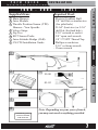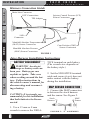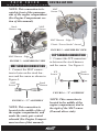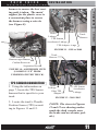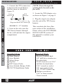
1
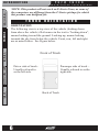
Ford
Juice
installation Instructions
**read important safety information in this manual**
TABLE OF CONTENTS
F o r d
J u i c e
I n s t a l l a t i o n
I n s t r u c t i o n s
TABLE OF CONTENTS
Table Of Contents
ABOUT THE JUICE...................................... 3
SAFETY TERMS ............................................................ 3
INTRODUCTION ......................................... 3
INTRODUCTION
PRODUCT REGISTRATION ............................................. 4
IMPORTANT NOTES ...................................................... 5
TRUCK ORIENTATION ................................................... 6
INSTALLATION .......................................... 7
1999 - 2003
(7.3L) ................................................... 7
INSTALLATION
BATTERY DISCONNECT ................................................
MAP SENSOR CONNECTION .........................................
MAT SENSOR CONNECTION ..........................................
ICP SENSOR CONNECTION ...........................................
CMP SENSOR CONNECTION .........................................
TPS SENSOR CONNECTION ..........................................
2003-2007
8
8
9
9
10
11
(6.0L) .................................................. 12
BATTERY REMOVAL...................................................... 14
PCM CONNECTIONS .................................................... 14
MAP SENSOR CONNECTION ......................................... 15
OPERATING INSTRUCTIONS
EGT PROBE INSTALLATION ......................................... 17
TAPPING AND PROBE INSTALLATION ............................. 17
CONNECTING THE PROBE TO JUICE .............................. 19
JAB INSTALLATION .................................................... 20
1999 to 2007 - JAB INSTALLATION ............................... 20
JUICE MODULE INSTALLATION ................................... 22
FINAL JUICE MODULE INSTALLATION ............................ 22
MOUNTING AND SECURING THE JUICE .......................... 22
FINAL INSPECTION .................................................... 23
APPENDIX
OPERATING INSTRUCTIONS ..................... 24
USING THE JUICE ..................................................... 24
OPERATING THE ATTITUDE MODULE .............................. 24
ADDITIONAL JUICE/ATTITUDE INFORMATION .................. 24
APPENDIX ............................................... 25
ENGINE COMPARTMENT (REFERENCE) ......................... 25
1999-2003 ................................................................. 25
2003-2007 ................................................................ 26
2
F o r d
J u i c e
I n s t a l l a t i o n
I n s t r u c t i o n s
T H E
J U I C E
Congratulations on purchasing the Edge Juice/Attitude system for
the Ford Power Stroke Diesel®.
INSTALLATION
This system offers many cutting-edge, additional features not
available with the factory setup. Since the Juice Module is an addon ECM, it uses data from your truck’s computer or engine control
module (ECM), and then enhances the factory settings to optimize
your truck’s performance. This product offers a wide variety of
amazing performance and safety features that can ensure you get
the driving experience you desire without damaging your valuable
truck.
INTRODUCTION
The Juice/Attitude system features an intelligent module (Juice)
that acts as an add-on Engine Control Module (ECM) for the
Power Stroke® Engine. This module is controlled and customized
in the cab of your truck by the Attitude monitor/controller.
TABLE OF CONTENTS
A B O U T
INTRODUCTION
Please take the time to thoroughly review all of the features and
product options outlined in this manual. Taking the time to understand how this product works and how to properly operate this
product will ensure that you have an extraordinary and safe driving
experience. If we can be of any assistance to help you get the most
from your product please call us at 888-360-3343. We are open
Monday through Friday from 8am to 5pm Mountain Time.
OPERATING INSTRUCTIONS
IMPORTANT: Read through these instructions completely so
that you understand each step prior to installation. Refer to CS/
CTS User Manual for Safety and Warranty information
APPENDIX
S AFET Y TER M S
Throughout this User Guide (hereafter noted as User Manual or
Manual) you will see important messages regarding your safety or
the protection of your vehicle. These messages are designated by
the words WARNING or CAUTION.
3
INTRODUCTION
F o r d
J u i c e
I n s t a l l a t i o n
I n s t r u c t i o n s
TABLE OF CONTENTS
WARNING indicates a condition that may cause serious
injury or death to you, your passengers or others nearby. Pay
careful attention to these Warning messages, and always comply
with them. They could save a life.
INTRODUCTION
CAUTION indicates a condition that could cause damage to your
vehicle. It is important to install and operate your EDGE product in conformance with instructions in this Manual. Caution
alerts you to particularly important things that will keep your
vehicle operating properly.
INSTALLATION
P R O D U C T
R E G I S T R AT I O N
PLEASE take the time to register your product on line at edgeproducts.com. Follow the instructions at link: http://www.edgeproducts.com/product_registration.php
OPERATING INSTRUCTIONS
BENEFITS OF PRODUCT REGISTRATION
APPENDIX
-Your Safety - Registering your product allows us to know exactly
which product you have and provide important product updates to
you that improve the quality and/or safety of the product.
-Enhanced Features - Almost all Edge products are easily updated
via the internet. We are constantly adding new features and improvements to our product that we know you will want to enjoy.
-Confirmation of Ownership - Provides a record in case of product loss, theft, or required warranty work. When you call us for
support our team will already have much of the information they
need to help you.
-Improved Product Development - Helps us better understand
you (our customer) and design products that meet your needs.
-Special Offers - Allows us to inform you about special offers on
accessories and/or new products that fit your vehicle and enhance
your driving experience.
4
F o r d
J u i c e
I n s t a l l a t i o n
I n s t r u c t i o n s
INTRODUCTION
N O T E S
TABLE OF CONTENTS
I M P O R TA N T
1. If you have used another tuner/programmer on
your truck, you will need to program your truck
back to stock before using the Attitude or Juice.
Failure to return to stock may result in PCM failure or engine
damage.
INTRODUCTION
2. Programming your vehicle may expose existing defects in your
vehicle’s PCM that could disable your vehicle. It is advised that
you do not program your vehicle in remote location in case of
vehicle failure.
INSTALLATION
OPERATING INSTRUCTIONS
3. All Edge modules and programmers are built to operate with
OEM calibrations. When you take your vehicle to a service center
they may, by your request or otherwise, update your vehicle’s
calibrations. Therefore it is important that you return your vehicle
to stock before taking it in for service. Edge updates its active
products (i.e. those currently being manufactured) to work effectively with updated OEM calibrations. However, this process can
take some time as Edge is not always made aware of calibration
changes made by the OEM. In the case of discontinued products,
Edge cannot ensure that your unit will work effectively if you take
your vehicle to a dealership and you are given, by your request or
otherwise, a new calibration.
4. For specific information regarding horsepower, torque, and other
APPENDIX
features available for this product:
(1) Go to www.edgeproducts.com
(2) Type the part number of your product in the “KEYWORD/
PART# SEARCH” and press enter.
(3) Click the link under “Description”
(4) Scroll down to the “DOWNLOAD VEHICLE SPECIFIC
HORSEPOWER, TORQUE, AND FEATURES CHART” link
and click on it.
(5) Find the information that is specific to your make and model.
5
F o r d
INTRODUCTION
J u i c e
I n s t a l l a t i o n
I n s t r u c t i o n s
TABLE OF CONTENTS
NOTE: This product will not work on E-Series Vans, as some of
the connectors are different from the F-Series pickups for which
this product was designed for.
T R U C K
O R I E N TAT I O N
INTRODUCTION
ORIENTATION
The following view is a top view of the vehicle (looking down
from above the vehicle). References in the text to “looking down”,
means looking toward the ground. Looking up, means looking
towards the sky from below the vehicle. Front, rear, left and right
are as noted below. See Figure below.
INSTALLATION
Front of Truck
Passenger side of truck –
Usually referred to as the
right side.
OPERATING INSTRUCTIONS
Driver side of truck–
Usually referred to
as the left side.
APPENDIX
Back of Truck
6
F o r d
J u i c e
I n s t a l l a t i o n
I n s t r u c t i o n s
-
2 0 0 3
- Electric/Cordless Drill
- 1/8” drill bit or similar size
(for pilot hole)
- 21/64” (best size) or 5/16”
drill bit (for final hole)
- 9/16” wrench or socket
- 5/8” open end wrench
- 1/8”-27 NPT Thread Tap
- Phillips screwdriver
- 5/16” or 8mm wrench
- 13mm wrench
INTRODUCTION
1 Main Harness
2 Juice Module
3 Throttle Position Sensor (TPS)
Harness - Year Specific
4 Velcro Strips
5 Zip Ties
6 EGT Sensor Probe
7 Juice Attitude Bridge (JAB)
8 CS/CTS Installation Guide
( 7 . 3 L )
Required Tools
TABLE OF CONTENTS
1 9 9 9
Supplied Items
I N S TA L L AT I O N
INSTALLATION
1
3
OPERATING INSTRUCTIONS
2
99-00
01-03
6
7
APPENDIX
4
5
8
REFER TO QUICK
INSTALL GUIDE
FOR INSTALL
Note: Depending on your year of truck,
you may not need everything provided.
7
F o r d
I N S TA L L AT I O N
J u i c e
I n s t a l l a t i o n
I n s t r u c t i o n s
Harness Connection Guide
TABLE OF CONTENTS
Main Juice Connector
Injector Control Pressure (ICP)
Sensor Connectors
EGT Connections
TPS Adapter
INTRODUCTION
JAB
Connector
Manifold Absolute Temperature
(MAT) Sensor Connectors
INSTALLATION
Cam Position (CMP)
Sensor Connectors
Manifold Absolute Pressure
(MAP) Sensor Connectors
FIGURE 1
Juice Harness Installation Instructions
OPERATING INSTRUCTIONS
BATTERY DISCONNECT
APPENDIX
WARNING An electrical charge or battery acid can
burn you. Battery gas can
explode or ignite. Take care
when working around the battery. Follow instructions in
the vehicle owner’s manual for
disconnecting and reconnecting a battery.
CAUTION: It is strongly recommended for this installation
that both batteries be disconnected.
1. Use a 13 mm or 8 mm
wrench to remove the NEGA-
8
TIVE terminal on each battery.
(The wrench size depends on
the battery style.)
2. Set the NEGATIVE terminal
aside and secure it so it does not
make contact with the battery
during the installation.
MAP SENSOR CONNECTION
1. Connect the MAP connectors
in between the stock harness
and the sensor. See Figure 2.
Stock
Harness
MAP
Sensor
FIGURE 2 - “T” ASSEMBLY
F o r d
J u i c e
I n s t a l l a t i o n
I n s t r u c t i o n s
Stock
Harness
MAT
Sensor
TABLE OF CONTENTS
NOTE: This connection is located in front of the passenger
side of the engine compartment
(See Engine Compartment section of this manual).
I N S TA L L AT I O N
MAP
Sensor
INTRODUCTION
MAT Harness - Edgee
Plastic “Power Stroke” shroud
ICP SENSOR CONNECTION
MAP Harness - Edge
ge
FIGURE 3 - ASSEMBLED VIEW
1. Connect the MAT connectors in between the stock harness and the sensor as shown in
Figure 4.
MAT
Sensor
ICP
Sensor
Stock
Harness
Stock
Harness
APPENDIX
FIGURE 6 - “T” ASSEMBLY
FIGURE 4 - “T” ASSEMBLY
NOTE: This connection is
located in the middle of the of
the engine compartment, and
under the waste gate control
solenoid (See Engine Compartment section of this manual).
OPERATING INSTRUCTIONS
MAT SENSOR CONNECTION
1. Connect the ICP connectors
in between the stock harness
and the sensor. See Figure 6.
INSTALLATION
FIGURE 5 - ASSEMBLED VIEW
NOTE: This connection is
located in the middle of the
engine compartment, and to
the right of the MAT sensor
(Towards driver side).
9
F o r d
I N S TA L L AT I O N
TABLE OF CONTENTS
ICP Harness - Edge
dge
J u i c e
I n s t a l l a t i o n
ICP
Sensor
S
I n s t r u c t i o n s
Metal
rt
Support
INTRODUCTION
Edge CMP
Harness
FIGURE 7 - ASSEMBLED VIEW
INSTALLATION
OPERATING INSTRUCTIONS
CAUTION: The ICP sensor
closely resembles the coolant
sensor which is located towards
the front of the engine. Figure
7 shows the proper location for
the ICP Sensor.
CMP SENSOR CONNECTION
The preferred method for routing the CMP harness is:
APPENDIX
1. Remove the plastic “Power
Stroke” cover located on top of
the engine.
2. Route the CMP harness
across the top of the engine, and
down towards the bottom of the
engine as shown in Figure 8. (It
is best to route along side the
factory wiring harness)
FIGURE 8 - ROUTING VIEW
3. Refer to Figure 10. The
CMP sensor is located on the
front of the engine. Looking
“up” from underneath the truck,
it will be above and towards
the passenger side of the main
pulley.
Engine
Harness
CMP
Sensor
FIGURE 9 - “T” ASSEMBLY
4. Once the CMP sensor is
located, and the Edge harness
plugged in, use zip ties to keep
all parts of the harness away
from the belt or other moving
parts.
(NOTE: Fasten the Edge
harness to the existing truck
10
F o r d
J u i c e
I n s t a l l a t i o n
I n s t r u c t i o n s
I N S TA L L AT I O N
TABLE OF CONTENTS
harness to ensure the best routing path is taken. The metal
support for the plastic cover is
a convenient place to secure
the harness using a wire tie
(see Figure 8).
Truck
Harness
INTRODUCTION
Brake
Linkage
TPS Sensorr
Accelerator Linkage
TPS Adapter - Edge
FIGURE 11 - 1999 to 2000
INSTALLATION
CMP
P Sensor
rness
Routed Edge Harness
Coolant Reservoir
Truck
Harness
OPERATING INSTRUCTIONS
Serpentine Belt
ltt
FIGURE 10 - ASSEMBLED VIEW
(LOOKING “UP” FROM
UNDERNEATH THE TRUCK)
TPS SENSOR CONNECTION
2. Locate the truck’s Throttle
Position Sensor (TPS) according to Figures 11 and 12.
T
P Sensor
TPS
Accelerator
Linkage
APPENDIX
1. Using the information on
page 7, locate the TPS Sensor
harness that is specific to your
truck.
Brake
Linkage
Edge TPS
Adapter
FIGURE 12 - 2001-2003
(NOTE: The views in Figures
11 and 12 are showing underneath the dash console near
the brake and accelerator pedals.)
11
F o r d
I N S TA L L AT I O N
J u i c e
I n s t a l l a t i o n
I n s t r u c t i o n s
TABLE OF CONTENTS
3. Connect the TPS connectors
in between the stock harness
and the sensor as shown in
Figure 13.
(NOTE: Route through the
existing holes located on the
fire wall.)
Stock
Harness
5. Locate the TPS Adapter wire
as shown in Figure 1 on page 8.
TPS
Sensor
INTRODUCTION
Plugs into Main Juice harness
FIGURE 13 - “T” Assembly
INSTALLATION
4. From in the cab, route the
TPS Sensor harness through
the fire wall and into the engine
compartment.
OPERATING INSTRUCTIONS
2 0 0 3 - 2 0 0 7
6. Plug the single wire adapter
into the end of the TPS Sensor
harness.
This concludes the Juice Harness section of the installation.
Please refer to the EGT PROBE
INSTALLATION section of
this manual to continue your
installation.
( 6 . 0 L )
APPENDIX
Supplied Items
Required Tools
1
2
3
4
5
6
7
- Electric/Cordless Drill
- 1/8” drill bit or similar size
(for pilot hole)
- 21/64” (best size) or 5/16”
drill bit (for final hole)
- 9/16” wrench or socket
- 5/8” open end wrench
- 1/8”-27 NPT Thread Tap
- Phillips screwdriver
- 5/16” or 8mm wrench
- 13mm wrench
12
Main Harness
Juice Module
Velcro Strips
Zip Ties
EGT Sensor Probe
Juice Attitude Bridge (JAB)
CS/CTS Installation Guide
F o r d
J u i c e
I n s t a l l a t i o n
I n s t r u c t i o n s
I N S TA L L AT I O N
TABLE OF CONTENTS
1
4
5
6
7
INSTALLATION
3
INTRODUCTION
2
Note: Depending on your year of truck, you may not need everything provided.
Harness Connection Guide
Attitude
Connection
Main Juice
Conn
Connector
EGT
Conn
Connections
Main Edge PCM Connectors
FIGURE 1
13
APPENDIX
Manifold Absolute Pressure
(MAP) Sensor Connectors
OPERATING INSTRUCTIONS
REFER TO QUICK
INSTALL GUIDE
FOR INSTALL
I N S TA L L AT I O N
F o r d
J u i c e
I n s t a l l a t i o n
I n s t r u c t i o n s
Juice Harness Installation Instructions
TABLE OF CONTENTS
NOTE: Refer to the Engine Compartment section of this manual
for general part locations under the hood.
INTRODUCTION
INSTALLATION
BATTERY REMOVAL
PCM CONNECTIONS
WARNING An electrical charge or battery acid can
burn you. Battery gas can
explode or ignite. Take care
when working around the battery. Follow instructions in
the vehicle owner’s manual for
disconnecting and reconnecting a battery.
1. Locate the PCM. It is shown
below in Figure 2.
CAUTION: For connector removal, follow the instructions
in step 3 to avoid damaging
your engine harness or PCM
connectors.
Removed
Battery
Location
CAUTION: It is strongly
recommended that both
batteries be disconnected.
OPERATING INSTRUCTIONS
1. Remove the battery cables
(negative first) using an 8 mm
wrench.
APPENDIX
2. Remove the driver side battery cover by releasing the tab
located on the left side of the
battery cover.
3. Completely remove the
driver side battery and set aside.
(This will allow you to easily
connect the Main PCM connectors into to the PCM.)
14
Removed
Center
Location
PCM
FIGURE 2 - PCM Location
2. Refer to Figure 3. In order
to remove the engine harness
from the PCM, the lever on the
harness connector needs to be
rotated away from the PCM.
This will allow you to safely
remove the harness.
F o r d
J u i c e
I n s t a l l a t i o n
I n s t r u c t i o n s
INTRODUCTION
PCM
Connector
CAUTION: To keep water from
causing damage to the engine
and Juice harnesses, route
the Juice harness as shown in
Figure 5. This will also insure
that the battery cover will fit
back into place.
TABLE OF CONTENTS
Engine
Harness
Lever
I N S TA L L AT I O N
PCM
FIGURE 3 - Connector Removal
Engine Harness
Battery Tray
Edge Harness
OPERATING INSTRUCTIONS
4. Connect the Main Edge
PCM Harness as described in
Figure 1 in between the PCM
and Engine harness as described
in Figure 4 below.
INSTALLATION
3. Disconnect the center harness as shown in Figure 2.
FIGURE 5 - Harness Routing
Engine
Harness
PCM
Connector
FIGURE 4 - PCM Installation
CAUTION: The two connectors should slide easily
together. DO NOT force the
two connectors together. If
the connectors do not slide
smoothly, inspect for bent pins,
and retry.
APPENDIX
Edge PCM
Harness
6. Replace the battery.
7. Reinstall battery cover.
8. Reconnect battery cables.
(Positive first.)
MAP SENSOR CONNECTION
1. Using the Engine compartment section of this manual,
locate the MAP Sensor.
2. Unplug the stock MAP harness, and insert the Edge MAP
Sensor harness in between the
15
F o r d
I N S TA L L AT I O N
I n s t a l l a t i o n
TABLE OF CONTENTS
MAP harness and the sensor.
Refer to Figure 6.
Engine
Harness
INTRODUCTION
Edge MAP
Harness
MAP Sensor
FIGURE 6 - “T” Assembly
INSTALLATION
3. Figure 7 shows an assembled
MAP harness. Note that the
MAP Sensor is bolted to the
backside of the bracket shown.
Oil Cap
OPERATING INSTRUCTIONS
APPENDIX
Bracket
MAP Sensor
Edge MAP
Harness
FIGURE 7 - Final Assembly
16
J u i c e
I n s t r u c t i o n s
4. Use zip ties to fasten the
harness. Keep all harness components away from hot engine
surfaces, as well as moving
parts.
This concludes the Juice Harness section of the installation.
Please refer to the EGT PROBE
INSTALLATION section of this
manual to continue your installation.
F o r d
J u i c e
I n s t a l l a t i o n
P R O B E
I N S TA L L AT I O N
1
INSTALLATION
2
Supplied Items
Qty
1 EGT Probe..................................(1)
2 Shrink Tube................................(2)
TAPPING AND PROBE INSTALLATION
1. Obtain a 1/8”-27 NPT Thread Tap available from your local
hardware store.
2. Drill a 21/64” (5/16” optional) hole through the manifold wall.
3. Use the pipe tap to cut the threads in accordance to the pipe tap
manufacturer’s instructions and recommendations.
4. Remove the fitting from the Thermocouple and install by tight-
17
APPENDIX
CAUTION: One effective way to avoid metal fragment contamination in your engine manifold is to apply grease in the tip of
the drill bit and threads of your tap tool when drilling/tapping
the hole in your manifold. Reduce pressure on the drill when the
drill breaks through the manifold wall to reduce risk of pushing
metal chips into the manifold.
OPERATING INSTRUCTIONS
Required Tools
- Electric/Cordless Drill
- 1/8” drill bit or similar size (for pilot hole)
- 21/64” (best size) or 5/16” drill bit
(for final hole)
- 9/16” wrench or socket
- 5/8” open end wrench
- 1/8”-27 NPT Thread Tap
- Phillips screwdriver
- 5/16” or 8mm wrench
INTRODUCTION
WARNING When installing the EGT (Exhaust Gas
Temperature) Thermocouple, wear eye protection and protective
clothing to protect from getting metal chips in your eyes. Also,
since exhaust manifolds can be very hot, allow the engine to cool
before drilling. When working under the vehicle, make sure the
park brake is set.
TABLE OF CONTENTS
E G T
I n s t r u c t i o n s
I N S TA L L AT I O N
F o r d
I N S TA L L AT I O N
J u i c e
I n s t a l l a t i o n
I n s t r u c t i o n s
TABLE OF CONTENTS
INTRODUCTION
INSTALLATION
OPERATING INSTRUCTIONS
ening the tapered thread end into
the manifold. (Figure 1)
Fitting
5. Tighten the fitting so that it is
Tapped Hole
securely seated.
6. Install the probe into the fitting,
and tighten the top nut of the fitExhaust Manifold Wall
ting just tight enough to keep the
Figure 1 - Fitting Installation probe firmly mounted. (Figure 2)
NOTE: Ideally the tip of the fitting would be less than or flush
with the inside of the exhaust flow
path. (Figure 2)
7. Make sure that the probe cable
Nut
is positioned to allow best path and
Fitting
minimal bending for routing to the
Flush
fire wall.
Probe
NOTE: The probe will move approximately 90 Deg. clockwise in
the direction the nut is tightened.
Figure 2 - Probe Insertion
Before fully tightening the nut,
make sure the cable starts 90
Degrees from the final resting poTo Fire wall
sition. When tightened, the cable
will be correctly positioned.
Tightened
APPENDIX
Position
90 Deg.
Starting
Position
Figure 3 - 90 Degree
Correct
CAUTION: Do not bend the
probe after installed. If needed,
loosen the probe nut, adjust the
probe, and re-tighten. Bending
the probe tubing will result in a
faulty probe.
Wrong
Figure 4 - DO NOT BEND
18
F o r d
J u i c e
I n s t a l l a t i o n
I n s t r u c t i o n s
2003-2007
TABLE OF CONTENTS
1999-2003
I N S TA L L AT I O N
INTRODUCTION
EGT Location per year range
1. Slide the shrink tube pieces over the two wires. Later you will
slide them over the bolted connections. (Figure 5)
Shrink Tube
Ring Terminals
3. Tighten the nuts so that each wire is in line with its mating wire.
4. Position the supplied shrink tube over the secure fasteners.
5. Center the connection within the shrink tube. Heat and shrink
19
APPENDIX
Figure 5 - Shrink Tube
2. Connect the (2) ring terminals
Nut
to the mating Juice harness terminals
using the supplied hardware.
Bolt
Yellow to Yellow. Red to Red.
Figure 6 - Hardware Install
(Figure 6)
OPERATING INSTRUCTIONS
CONNECTING THE PROBE TO JUICE
INSTALLATION
NOTE: Find these exhaust manifold locations by laying on
your back behind the driver side front tire and looking up. The
1999-2003 view shows only the fitting having been installed. The
2003-2007 view shows the Probe mounted to the fitting.
F o r d
I N S TA L L AT I O N
J u i c e
I n s t a l l a t i o n
I n s t r u c t i o n s
the tubing over the connections. (Figure 7)
TABLE OF CONTENTS
Figure 7 - Shrink Tube Final
6. Secure the excess cable to the existing engine wire harnesses
with supplied zip ties.
INTRODUCTION
J A B
I N S T A L L AT I O N
NOTE: The CS/CTS will not function unless the JAB is properly
installed and plugged into both the Juice Module and Attitude
Monitor (CS/CTS).
1999 to 2007 - JAB INSTALLATION
INSTALLATION
CS/CTS Connection
1. Locate the green connector on
the Juice Harness and plug it into
the Green connector on the JAB.
OPERATING INSTRUCTIONS
2. Under the hood, connect the 3
EAS components to one another.
A “click” will be felt and heard
indicating that the connectors are
JAB Adapter “T”
correctly fastened.
Figure 1 - Juice Harness
End Cap
APPENDIX
Green Connectors
Figure 2 - JAB System
3. Route the CS/CTS Connector and cable through the fire wall
grommet. The JAB and Juice Module will remain under the hood.
(Figure 3)
20
F o r d
J u i c e
I n s t a l l a t i o n
I n s t r u c t i o n s
I N S TA L L AT I O N
TABLE OF CONTENTS
Engine Side
Cab Side
EAS Connector
CS/CTS
Connector
INTRODUCTION
Grommet
Fire Wall
Figure 3 - Fire Wall Routing
CS/CTS
Connector
INSTALLATION
4. Route the cable from below the
dash up to the lower left corner of the
driver side windshield. (Figure 4)
5. If needed, remove side panels to
help see while routing.
NOTE: For a clean look, the cable
can be hidden behind the dash plastic and the door frame weather strip.
Grommet
7. Using the supplied zip ties, fasten the JAB connectors underneath the overhang which runs across the top of the fire wall.
(Figure 5 - On next page)
8. Keep the JAB assembly close to the driver side.
21
APPENDIX
Figure 4 - In Cab Routing
OPERATING INSTRUCTIONS
6. Leave enough length between the
dash and the end of the CS/CTS connector for easy CS/CTS install.
F o r d
I N S TA L L AT I O N
J u i c e
I n s t a l l a t i o n
I n s t r u c t i o n s
Fire Wall
Overhang
TABLE OF CONTENTS
Zip Ties
To CS/CTS
INTRODUCTION
JAB Assembly
To Juice
INSTALLATION
Figure 5 - Securing JAB
(Looking from the front of the truck to back)
OPERATING INSTRUCTIONS
J U I C E
M O D U L E
I N S TA L L AT I O N
FINAL JUICE MODULE INSTALLATION
1. Plug the “Main Juice Connector” into the “Juice Module” receptacle. (Figure 1)
Juice
Module
APPENDIX
Main Juice
Harness
Figure 1 - Juice Module
MOUNTING AND SECURING THE JUICE
1. Attach one side of each Velcro strip to the back side of the Module and to the top side of a flat surface under the hood.
(NOTE: The best place is the top of the fuse box on the driver
side. This will secure the Juice module and help keep it away
from any moving or hot components under the hood.)
22
F o r d
I N S TA L L AT I O N
F I N A L
I N S P E C T I O N
I n s t a l l a t i o n
I n s t r u c t i o n s
1. Recheck all connections for a properly secure installation.
2. Using the supplied wire ties, secure the wiring harness and cable
to prevent possible heat damage from hot engine surfaces. (For the
7.3L, pay special attention to the routing of the CMP harness as it
is very close to moving parts.)
If you continue to have problems, contact your dealer or Edge
Products, LLC.
(888) 360-EDGE (3343) 8:00 am - 5:00 pm MST
INSTALLATION
4. Start the engine. The engine should start and idle like a stock
truck. If the engine does not start or run properly, turn off the
engine. Remove the keys from the ignition, and check the Juice
module connections. Make sure all connectors are fastened tightly.
INTRODUCTION
3. Reconnect the battery cables.
TABLE OF CONTENTS
J u i c e
OPERATING INSTRUCTIONS
APPENDIX
23
O P E R AT I N G I N S T R U C T I O N S
TABLE OF CONTENTS
U S I N G
F o r d
J u i c e
I n s t a l l a t i o n
T H E
I n s t r u c t i o n s
J U I C E
OPERATING THE ATTITUDE MODULE
Refer to the CS/CTS User Manual for detailed descriptions on how
to operate the Attitude Monitor.
ADDITIONAL JUICE/ATTITUDE INFORMATION
INTRODUCTION
EGT’s
EGT stands for exhaust gas temperature, and is the single most
important indicator of how a diesel engine is performing. Unlike
a gasoline motor, a diesel motor will continue to make power as
more fuel is added. As more fuel is added, the engine heat will
also increase. Please be aware of the limitations of a stock engine.
INSTALLATION
OPERATING INSTRUCTIONS
ENGINE CODES
As with many aftermarket electronic performance modifications
available for the Ford 7.3L Power Stroke® Diesel engine the Ford
7.3L Edge Products Juice module for the Ford 7.3 Power Stroke®
Diesel engine will likely set engine “codes.”
The engine codes are generally set during heavy acceleration.
Although the codes will remain “set” in the PCM, the dash board
indicator light should turn off within 15 minutes. Most codes that
are set under hard acceleration are called “soft codes”. These soft
codes are retained in the PCM and can be erased by using the Edge
Products CS/CTS to clear the codes.
APPENDIX
Codes that may be set:
•
P1211 – Injector control pressure is different than expected
•
P1209 – Peak injection pressure fault
24
F o r d
J u i c e
I n s t a l l a t i o n
I n s t r u c t i o n s
APPENDIX
1999-2003
MAP
Sensor
MAT
Sensor
ICP
Sensor
TABLE OF CONTENTS
ENGINE COMPARTMENT (REFERENCE)
INTRODUCTION
INSTALLATION
OPERATING INSTRUCTIONS
Suggested
Juice Module
Location
APPENDIX
CMP
Sensor
25
F o r d
APPENDIX
J u i c e
I n s t a l l a t i o n
I n s t r u c t i o n s
2003-2007
TABLE OF CONTENTS
MAP
Sensor
PCM
INTRODUCTION
INSTALLATION
OPERATING INSTRUCTIONS
APPENDIX
Suggested
Juice Module
Locations
26
F o r d
J u i c e
I n s t a l l a t i o n
I n s t r u c t i o n s
APPENDIX
TABLE OF CONTENTS
INTRODUCTION
INSTALLATION
OPERATING INSTRUCTIONS
APPENDIX
27
Copyright© 2010 Rev 00
For additional questions not found in the user guide call:
Edge Products Technical Support: (888) 360-EDGE (3343) 8:00 am - 5:00 pm MST
To expedite your support call, please have your Vehicle Information,
Part Number, and Serial Number ready prior to calling Technical Support.
The Edge Products information is found on the label located
on the bottom of the device.