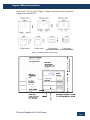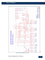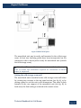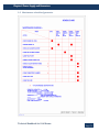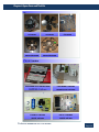
1
TECHNICAL HANDBOOK WALK‐IN‐FREEZER FOR THE REPAIR AND MAINTENANCE OF WALK-IN-COOLER/FREEZERS TECHNICAL HANDBOOK FOR THE REPAIR AND MAINTENANCE OF WALK-IN-COOLER/FREEZERS Edition: April, 2009 TABLE OF CONTENTS TECHNICAL HANDBOOK ................................................................................. 1 FOR THE REPAIR AND MAINTENANCE OF.................................................. 1 WALK-IN-COOLER/FREEZERS ....................................................................... 1 TECHNICAL HANDBOOK ................................................................................. 2 FOR THE REPAIR AND MAINTENANCE OF.................................................. 2 WALK-IN-COOLER/FREEZERS ....................................................................... 2 Chapter 1: Effective vaccine store ........................................................................... 1 Introduction................................................................................................................................................... 2 Space planning.............................................................................................................................................. 2 2.1 Planning vaccine store...................................................................................................................... 2 2.2 Vehicle loading bay ............................................................................................................................ 3 2.3 Refrigeration equipment area....................................................................................................... 3 2.4 Vaccine packing area ........................................................................................................................ 5 2.5 Choosing a site...................................................................................................................................... 7 3 Building standards....................................................................................................................................... 8 4 Vaccine Safety........................................................................................................................................... 10 1 2 Chapter 2: Cold rooms .......................................................................................... 16 1 2 3 4 5 6 Technical specifications of cold rooms/freezer rooms......................................................... 17 1.1 Specifications of WIC .......................................................................................................................17 1.2 Specifications of WIF .......................................................................................................................20 Procedure for Installation of cold room........................................................................................... 25 2.1 Installation of panel.........................................................................................................................27 2.2 Installation of shelves......................................................................................................................29 2.3 Installation of room light & connecting door heater......................................................29 2.4 Installation of pressure ventilator (Breeder).......................................................................29 Engineering diagrams for assembling and installation of WIC/WIF....................................... 30 Components of WIC/F............................................................................................................................. 41 4.1 Cold room panels ...............................................................................................................................41 4.2 Cooling units........................................................................................................................................41 4.3 Cooling unit (EUROMON2) ...........................................................................................................44 4.4 Cold/freezer room control panel ...............................................................................................49 Cold room programming........................................................................................................................ 49 5.1 Factory setting....................................................................................................................................50 5.2 Modifying the master log settings .............................................................................................53 5.3 Interpreting the operating messages.......................................................................................56 5.4 Diagnosis of problems .....................................................................................................................56 Alarm System ............................................................................................................................................. 58 6.1 Installation ...........................................................................................................................................58 6.2 Operation ..............................................................................................................................................59 6.3 Setup........................................................................................................................................................59 6.4 Maintenance ........................................................................................................................................60 Chapter 3: Preventive maintenance...................................................................... 62 1 2 3 4 Routine Maintenance ............................................................................................................................ 63 Daily Check‐Up........................................................................................................................................... 64 Weekly checks............................................................................................................................................ 65 Monthly checks ......................................................................................................................................... 66 5 Monitor routine and emergency maintenance ............................................................................. 67 Chapter 4: Power supply and generators .............................................................. 68 1 Generator and control panel................................................................................................................ 69 1.1 Engine.....................................................................................................................................................69 1.2 Alternator .............................................................................................................................................69 1.3 Control Panel.......................................................................................................................................69 1.4 Installation ...........................................................................................................................................70 1.5 Sequence of operation of relays in control ............................................................................71 1.6 Maintenance schedule of generator .........................................................................................73 Chapter 5: Temperature monitoring ..................................................................... 74 Thermometers ........................................................................................................................................... 75 Temperature plotters.............................................................................................................................. 76 Computerized temperature recorders ............................................................................................. 76 3.1 Multichannel computerized temperature monitoring system ...................................76 3.2 Wireless temperature data logger ............................................................................................82 1 Temperature indicators....................................................................................................................... 87 1.1 Vaccine Vial Monitor (VVM).........................................................................................................87 1.2 FridgeTag............................................................................................................................................88 1.3 FreezeTag............................................................................................................................................89 2 Summary..................................................................................................................................................... 90 1 2 3 Chapter 6: Spare parts and Tool kit ....................................................................... 91 3 4 List of spare parts ................................................................................................................................... 92 Toolkit for Refrigerator technician...................................................................................................102 Chapter 7: troubleshooting................................................................................. 106 1 Possible faults, observations and repair actions for cold rooms ..........................................107 Abbreviations Abbreviation Definition 0 C Degree Celsius A Ampere AC Alternate Current AMC Annual Maintenance Contract BCG Bacille Calmette‐ Guérin (tuberculosis vaccine) CFC Chlorofluorocarbon Cm Centimeter DC Direct Current DG Diesel Generator DPT Diphtheria, Pertusis and Tetanus DT Diphtheria, and Tetanus EEFO Early Expire First Out FIFO First in First Out GMSD Government Medical Store Depot Hept. B Hepatitis B Hz Hertz (Cycle per Second) IP Ice‐packs KVA Kilo Volt Ampere KW Kilo Watt M Meter Mfd Micro farad Abbreviation Definition OPV Oral Polio Vaccine RPM Rotation per Minute T.T Tetanus Toxoid UIP Universal Immunization Programme V Volt VVM Vaccine Vial Monitor WIC Walk‐in‐Cooler WIC/F Walk‐in‐cooler/Walk‐in‐freezer WIF Walk‐in‐Freezer Acknowledgement The technical handbook for repair and maintenance of cold rooms was prepared with technical contributions from State Health Transport Office (SHTO) Pune (Government of Maharashtra), Ministry of Health and Family Welfare, Government of India and UNICEF. Generous financial support from Norway India Partnership Initiative (NIPI) facilitated development of this training handbook. Chapter 1: Effective Vaccine Store Contents $Introduction This handbook has been prepared for refrigeration technicians for repair and maintenance of cold rooms/freezer rooms. It offers technical guidance and reference material for components of cold/freezer rooms. Introduction section guides the reader on how to use this book. $Guidelines for effective vaccine store Cold room is the storage facility where large quantities of vaccines could be stored for longer duration.. Cold/freezer rooms have been installed at National Stores (GMSD) (also referred as primary stores) and State/Regional/Divisional stores (also referred as intermediate stores). To effectively manage these vaccine stores, WHO has issued guidelines (WHO/V&B/02.341). This section has incorporated these guidelines for ready reference. These provide general rules for deciding the ideal location of cold/freezer rooms and establish required standards of electric supply and power connections. It also provides the standards on adequate size of vaccine storage area, packaging area and store keeper’s layout. $How to look after cold room and freezer room This section guides users on basics of how to look after the cold room and freezer room. 1 Guidelines for establishment or improving primary and intermediate vaccine stores. Vaccine and Biologicals, World Health Organization, Geneva. 2002 CChhaapp t teerr 11 EEffffeeccttiivvee VVaacccciinnee SSttoorree 1 Introduction One of the most important links in the cold chain is Walk‐in‐ Cooler/Freezer‐Rooms (WIC/F). Walk ‐in ‐coolers (WIC) are used for bulk storage of vaccines at + 20 C to + 8 0 C and Walk ‐in ‐Freezer ‐ (WIF) for storage of vaccines at (‐) 250 C to (‐) 150 C. WIF also support preparation of ice‐ packs (IP) at State level or Regional level storage. The name “Walk‐in” means that one can walk into the storage spaces inside these rooms. India is using cold chain infrastructure which was established gradually since 1985. As a result cold chain equipment of various make and mixed technology could be found in the vaccine stores. This situation creates special challenges for refrigeration mechanics to service and maintain the equipment of technology ranging from 20 years old to the latest models. In the recent years there has been significant change in refrigeration technology and instrumental control design. Though the basic functions of the equipment remains the same, there is considerable advances in their design like introduction of CFC free refrigerants, modern control systems with microprocessors, built in electronic switching devices, digital display, blister type operating switches etc. Maintenance work now requires new repair tools, instruments and equipment.2 Only the minimum information that is required for day to day repair and maintenance have been provided. For more technical detail, please refer to equipment manual.. 2 Space planning 2.1 Planning vaccine store Space is required in a vaccine store for a vehicle loading bay, a room to accommodate the refrigeration equipment, a room to store dry stores such as diluents, droppers, packing materials and other consumables such as injection equipment, waste management supplies and spare parts, a room to pack the vaccine for dispatch, and an office for the storekeeping staff. If possible the different activities should be housed in the same building, although bulky consumables such as injection equipment and spare parts may have to be stored elsewhere. 2 A list of recommended tools & instruments is given separately towards the end of this handbook TTeecchhnniiccaall H Haannddbbooookk ffoorr CCoolldd RRoooom mss Page 2 CChhaapp t teerr 11 EEffffeeccttiivvee VVaacccciinnee SSttoorree 2.2 Vehicle loading bay The detailed design of a vehicle loading bay is governed by the size and type of vehicle used. Consideration should be given to: 1. Access: The loading bay and the route to it must be planned to allow easy access for the largest vehicle used. 2. Security: Vaccines are high cost value. The loading bay area should therefore be visible from the storekeeper’s office to ensure security. 3. Weather protection: A loading bay should preferably have a projecting canopy to protect workers, vehicles and vaccines from sunlight, rain or snow during loading and unloading. 4. Loading dock: Delivery vans can be loaded from ground level. However, it is more convenient to load and unload lorries from a loading dock that is at the same level as the floor of the vehicle. This makes it possible to use a trolley to wheel vaccine into the vehicle. A raised loading dock should be between 1.2 and 1.4 metres above the vehicle parking area. Ideally, it should be built to match the height of the delivery vehicle. 5. Special requirements for refrigerated vehicles: Some states have refrigerated vehicles to distribute vaccine from the primary store to intermediate stores. A refrigerated vehicle must be fitted with a temperature logger; there should be a weatherproof electrical outlet to power the vehicle’s refrigeration unit during loading and unloading operations; and there should be sufficient space to store delivery crates if these are used in place of cold boxes. 2.3 Refrigeration equipment area The refrigeration equipment area should be laid out so that diluents and OPV droppers can be stored nearby on easily accessible shelves close to the cold store. Each vaccine manufacturer supplies diluent that is only compatible with its own vaccine. It is very important that diluents be systematically stored and subjected to the same rigorous stock control procedures as the vaccines with which they are intended to be used. Experience shows that good control of diluent stock is more likely to be achieved when it is stored close to the vaccine with which it is to be used. The information in this section assumes that prefabricated cold stores with twin‐ packaged refrigeration units are in use. Figure 1 shows typical layouts and clearances for cold stores in a range of TTeecchhnniiccaall H Haannddbbooookk ffoorr CCoolldd RRoooom mss Page 3 CChhaapp t teerr 11 EEffffeeccttiivvee VVaacccciinnee SSttoorree sizes from 5 m3 to 40 m3. Figure 2 shows the layout and clearances required around WIC/F. Figure 1: Standard sizes of cold rooms TTeecchhnniiccaall H Haannddbbooookk ffoorr CCoolldd RRoooom mss Page 4 CChhaapp t teerr 11 EEffffeeccttiivvee VVaacccciinnee SSttoorree Figure 2: Overview of a vaccine store with a cold room The internal height of WIC/F where stock is moved by hand should not exceed 2.3 metres. This limit ensures that the vaccine on the top shelves is accessible without the use of steps. WIC/F should be planned so that they accommodate the greatest possible length of shelving, taking into account the locations of the entrance door and the refrigeration units. A square plan is not necessarily the most space‐ efficient, especially in smaller units. Vaccine boxes should be arranged so that there is free movement of air between the vaccine packages, which should be stored about 5 cm away from the walls of the room. This allows air movement behind the stock and ensures an even temperature. Slatted shelving also assists air circulation and is therefore preferable to solid shelving. 2.4 Vaccine packing area Figure 3 is a schematic layout for a typical vaccine packing area. The size of the space required depends on the maximum daily transaction and the number of staff employed. The packing area should connect to a direct route between the WIC/F and the vehicle loading area. It must not form part of a main circulation route because it has to be kept cool possibly by air‐conditioning and secure. Vaccine packing involves a number of linked activities, all of which should be accommodated in the same space. TTeecchhnniiccaall H Haannddbbooookk ffoorr CCoolldd RRoooom mss Page 5 CChhaapp t teerr 11 EEffffeeccttiivvee VVaacccciinnee SSttoorree Figure 3: Organization diagram and layout of packing area The packing area should be laid out so as to encourage a logical flow of work. Vaccines should be moved as little as possible in order to minimize the risk of breakage. There should be a sink in the packing area for hand‐washing and provision for hygienic hand‐drying. TTeecchhnniiccaall H Haannddbbooookk ffoorr CCoolldd RRoooom mss Page 6 CChhaapp t teerr 11 EEffffeeccttiivvee VVaacccciinnee SSttoorree 2.5 Choosing a site The checklist below outlines the main steps in the process of site selection. 1. Determine the size of the store and its access requirements: Using the information given above, calculate the floor area required for the vaccine store and the size of delivery vehicles. 2. Review potential sites: Consider the following alternatives. a) Space in a government warehouse or other government building that can be adapted for the purpose. b) Commercial warehouses that can be purchased or rented. c) Empty sites that can be developed. 3. Assess natural hazards: Consider the following. a) Are any of the potential sites at particular risk from natural hazards, e.g. tidal surges, storms or earthquakes? b) What precautions can be taken to guard against these risks? c) If any of the preferred sites were to be severely damaged, how would this affect the routine immunization programme and a post‐ disaster emergency response? 4. Compare the suitability of possible sites: Consider the following issues before a site is finally selected: Access a) Is the site close to the relevant transport links, including roads and airport? b) Is the site well served by public transport? Public transport is needed by store staff. It may also be required by health workers when collecting vaccine. c) Is the site conveniently located for permanent and supervisory staff? d) Is the route to the site accessible throughout the year? e) Is there adequate access and parking space for vehicles? Services a) Does the site have a reliable mains electricity supply? TTeecchhnniiccaall H Haannddbbooookk ffoorr CCoolldd RRoooom mss Page 7 CChhaapp t teerr 11 EEffffeeccttiivvee VVaacccciinnee SSttoorree b) Is there a stand‐by generator? c) Does the site have a reliable telephone service? Security a) Would the site be secure? b) Could the store be properly monitored and supervised outside normal working hours? Site development a) Is the site well drained and without any risk of flooding? b) Are ground conditions suitable for building economically? c) Could the site be developed at an acceptable cost? 3 Building standards Vaccine stores should be housed in permanent buildings, which should be designed and constructed to a good standard that is appropriate for local climatic conditions. Temporary buildings should be avoided since it is difficult to relocate WIC/F. They are rarely satisfactory and are expensive to maintain. If the store is in an area affected by flooding it should be on high ground or raised above flood level. The loss of a major vaccine store in a natural disaster has potentially life‐threatening consequences for the population concerned. If an existing building is used it must be in good condition. If necessary it should be repaired and upgraded first. The following minimum standards are desirable in any vaccine storage building. Most are essential in a primary or intermediate store. Roof and ceilings Roof and ceiling of the cold rooms should be in good condition, completely free from leaks. Roof space should be insulated and/or ventilated in hot climate areas and insulated in cold climate areas. Ceiling should be in good condition and freshly painted. The ceiling should completely seal off the roof space in order to protect against dust and pests. Walls and columns TTeecchhnniiccaall H Haannddbbooookk ffoorr CCoolldd RRoooom mss Page 8 CChhaapp t teerr 11 EEffffeeccttiivvee VVaacccciinnee SSttoorree Should be in good condition, free of cracks and other structural defects. Free from rising or penetrating damp, termites. Insulated in cold climates. Insulations should be nicely finished internally and externally to a good standard. The internal finishes should be dust‐free. Windows, screens and doors Windows should be in good condition, with no broken glass, and should have secure locks or catches. All window openings should be fitted with security grilles. All external doors and all internal doors to rooms containing valuable items should be fitted with security locks. Floors Flooring should be smooth, level and completely free from rising damp. Suitably finished with floor paint, tiles, terrazzo, vinyl sheet or some other washable dust‐free surface. Floors on which cold stores are to be built must be leveled to a tolerance of ±3 mm over the area of the cold store. It is desirable for cold stores to be raised on a low plinth (25‐50 mm). This prevents water used for floor washing from running under the floor panels. Alternatively, the junction between the cold store and the floor may be sealed with waterproof mastic. Fire protection The building should be easily accessible to the fire service. A water hydrant should be provided if this is required by the fire service. The building should not contain a kitchen or other significant fire hazard. The building should be of non‐combustible construction or should be lined with non‐combustible sheet materials. Rooms used for storing packing materials and other combustible items should be isolated from the vaccine store by fire‐resisting construction and by fire‐resisting self‐closing doors. Flammable rubbish, such as cartons and boxes, must not be allowed to accumulate in the store. Smoking should be forbidden and “No Smoking” signs should be displayed throughout the store. The building should be fitted with fire and smoke detectors connected to an external alarm sounder. TTeecchhnniiccaall H Haannddbbooookk ffoorr CCoolldd RRoooom mss Page 9 CChhaapp t teerr 11 EEffffeeccttiivvee VVaacccciinnee SSttoorree There should be at least one carbon dioxide or powder fire extinguisher close to the entrance door for extinguishing electrical fires. In addition there should be at least two carbon dioxide, powder or water extinguishers within 30 metres of any part of the vaccine store for extinguishing other types of fire. Fire‐detection and fire‐fighting equipment must be inspected regularly, and staff must receive adequate training in fire‐fighting techniques and emergency action. There should be regular fire drills. Electrical services All power and lighting circuits must be in a safe condition, tested and approved to national standards by a qualified engineer or electrician. Power circuits serving refrigeration equipment must be rated to suit the required refrigeration starting and running loads. Ancillary electrical equipment (fans, air‐conditioners, light fittings, etc.) should have no significant electrical or mechanical defects. Heating and water supply systems All pipe‐work should be in good condition, free of leaks. Heating systems should be fully operational and controllable. Drainage Drainage systems should be fully operational and free of blockages. The surface water drainage system to the building and site must be effective even at the height of the rainy season. Pest control The building should be designed and maintained so as to minimize infestation by insects, termites, rodents, bats or other pests. Cleaning The building should be cleaned two or three times a week and adequate equipment should be available for this purpose. Security The building should be secured against break‐ins and should be located so that access to it is controlled. 4 Vaccine Safety The primary task when looking after a cold room or freezer room is to protect the vaccines from damage. All vaccines are virtually TTeecchhnniiccaall H Haannddbbooookk ffoorr CCoolldd RRoooom mss Page 10 CChhaapp t teerr 11 EEffffeeccttiivvee VVaacccciinnee SSttoorree damaged if they are exposed to excessively high temperatures. On the other hand, some vaccines are quickly destroyed if they are frozen. Damaged vaccines lose their potency and children who are immunized with such vaccines are not protected against those diseases. Know correct storage temperature of each vaccine. Learn the correct storage temperature for each vaccine. Keep a storage temperature checklist in the vaccine store so that you can check if you are in doubt. Primary Intermediate State -15°C to -25°C BCG WHO no longer recommends that freezedried vaccines be stored at -20°C. Storing them at -20°C is not harmful but is unnecessary. Instead, these vaccines should be kept in refrigeration and transported at +2°C to +8°C. MMR MR Health post District OPV Measles Health centre YF +2°C to +8°C Hib freeze-dried HepB DT DTP DTP-HepB Hib liquid Td TT Diluent vials must NEVER be frozen. If the manufacturer supplies a freeze-dried vaccine packed with its Diluent, ALWAYS store the product at between +2°C and +8°C. If space permits, diluents supplied separately from vaccine may safely be stored in the cold chain between +2°C and +8°C. Figure 4: WHO norms for storing vaccine Temperature sensitivity of vaccines WHO recommends the range of temperatures for storing and transporting vaccine on the basis of data supplied by manufacturers. Each vaccine has its own specific storage requirements so it is extremely important to know how long, and at what temperature, each vaccine can be stored. TTeecchhnniiccaall H Haannddbbooookk ffoorr CCoolldd RRoooom mss Page 11 CChhaapp t teerr 11 EEffffeeccttiivvee VVaacccciinnee SSttoorree All vaccines can be stored at positive temperatures (between +2 °C and +8 °C). However, only some vaccines can be stored at negative temperatures (between ‐15 °C and ‐25 °C). Loss of potency due to heat Vaccines that have been exposed to temperatures above +8 °C may lose their potency over time. The vaccine vial monitor (VVM) must always be used to guide decisions on the use of vaccine. Freezing The “T‐series” of vaccines (DTP, DT, dT, Td, TT), HepB, liquid Hib and liquid pentavalent vaccine should always be stored between +2 °C and +8 °C as they are damaged by freezing; they may also be damaged by exposure to freezing temperatures. HepB is the vaccine most sensitive to freezing temperatures. The most common cause of exposure to freezing temperatures is the failure to correctly condition ice packs prior to transport. To reduce the overall risk of freeze damage to vaccines, one should follow the best practices as outlined in the Aide‐memoire for prevention of freeze damage to vaccines given at the end of this manual (WHO/IVB/07.09). If it is suspected that vaccines have been exposed to freezing temperatures, perform the “shake test” (see Annex 3) before deciding whether the vaccine is damaged or not. A VVM does not indicate if a vaccine has been frozen. Standard operating procedures in WIC/F Keep door closed & locked Use internal plastic strip curtain. Avoid opening the WIC/F door unless it is absolutely necessary to do so. If the WIC/F is not fitted with an internal plastic strip curtain, always close the door when you are working inside. (Important: Check before hand that WIC/F could be opened freely from inside and you wear proper winter clothing) Switch off internal light when not needed. Switch off the interior light as soon as you have finished working inside. The light bulb gives off heat and this makes the refrigeration plant run longer than necessary. Lock the door Keep the WIC/F locked and make one person responsible for the key. Make sure that a spare key is kept in a safe place. Monitor storage temperature at least twice a day. TTeecchhnniiccaall H Haannddbbooookk ffoorr CCoolldd RRoooom mss Page 12 CChhaapp t teerr 11 EEffffeeccttiivvee VVaacccciinnee SSttoorree Monitor the temperature of every WIC/F at least twice a day and record it in the log book. Stack vaccine correctly Make sure the sufficient space around the vaccines for air circulations. Leave a gap of 5 cm from the wall and the vaccine box. Do not allow overloading. Do not keep vaccine on the floor of the WIC/F. Stack the vaccine in shelves only. Never keep freeze sensitive in front of evaporators. Never keep any vaccine underneath the cooling units. (Dripping water may damage vaccine boxes) Never keep any loose vial in the cold room. Follow EEFO and FIFO Store vaccine so that ‘Early Expiry First Out’ (EEFO) and ‘First in First out’ (FIFO) could be easily followed. Necessary adjustment should be made for VVM status. Make sure that vaccine is stacked on the shelves systematically so as to encourage EEFO/VVM stock management. Vaccines with early expiry or advance stage of VVM should be stored on top or front for early delivery. Avoid freezing. Vaccine can freeze inside a WIC for any of the following reasons: 1. Vaccine stored too close to evaporator. The air coming from the evaporator may be below 0°C until it has mixed properly with the air in the room. The danger zone typically extends for 50 cm in front of the evaporator. Vaccine must not be stored within this zone. 2. Thermostat set incorrectly. This may reduce the temperature throughout the room to below 0°C. • Temperature monitoring is not regular that in turn fails to identify low temperature for corrective action • Not properly conditioning3 the ice‐packs before putting them in cold boxes for vaccine transportation 3 Procedure to condition the ice-packs: (1) remove ice-packs from freezer, (2) keep at room temperature on table to allow their temperature to rise to 0°C – beads of water cover their surface and ice inside moves on shaking, (3) use the ice-packs in cold box/vaccine carrier. Now ice-packs cannot freeze the vaccine! TTeecchhnniiccaall H Haannddbbooookk ffoorr CCoolldd RRoooom mss Page 13 CChhaapp t teerr 11 EEffffeeccttiivvee VVaacccciinnee SSttoorree 3. In cold climates where the cold room is located in an unheated space, the temperature outside the cold room is close to or below 0°C the vaccine inside the room may freeze. A cold room in a cold climate should be built in a space that is permanently heated. Alternatively, it should be fitted with a thermostatically controlled heater circuit that maintains the inside temperature between +2°C and +8°C, even if the outside temperature is below 0°C. Out side heaters can also be provided to increase the ambient temperature. Make a contingency plan Make sure you know what to do if the WIC/F room breaks down. Every vaccine store must have a contingency plan for keeping vaccine safe if the refrigeration equipment fails. It is impossible to give precise directions about how this should be done, as circumstances vary. Whatever the circumstances, however, the following three rules apply in an emergency. Some of the possible contingency options are indicated below. • Move the vaccine to another cold store (Government or private). • Borrow or hire a refrigerated vehicle. • Obtain ice from a commercial ice‐maker and store it inside the WIC/F in plastic or metal containers. Closely monitor the room temperature and keep the ice supply replenished until repairs are carried out. Warning: Never use dry ice. Dry ice may lower the temperature of the WIC to below 0°C. Moreover, when it evaporates (sublimes) it gives off carbon dioxide gas. This may build up in the cold room and could suffocate anybody who enters the room. Follow the guidance given below for making contingency plan. • Prepare at least two alternative plans. • Whatever plans you choose, make sure they are discussed and agreed beforehand with your staff and with all the other parties involved. • Confirm the plan in writing. Keep a copy in the vaccine store. Make sure all staff knows where it is. • Check alternative stores to ensure that they are in good condition, have adequate space and are capable of maintaining vaccine at the correct temperature. There is no point moving TTeecchhnniiccaall H Haannddbbooookk ffoorr CCoolldd RRoooom mss Page 14 CChhaapp t teerr 11 EEffffeeccttiivvee VVaacccciinnee SSttoorree stock to another cold room if the result is that all your freeze‐ sensitive vaccine is frozen and destroyed. • Do not wait until an emergency occurs. Rehearse the plans before they are needed. • Prepare a list of emergency contact names, addresses and telephone numbers and post a copy of the list in the vaccine store. Keep the list up to date. • Make sure that emergency contacts can be made both inside and outside normal working hours. TTeecchhnniiccaall H Haannddbbooookk ffoorr CCoolldd RRoooom mss Page 15 Chapter 2: Cold rooms Contents The cold rooms in India have been sourced from various manufacturers. It is not possible to provide comprehensive information of all the models in use however this section is based on cold rooms supplied by HURREE. The information is by and large applicable to most of the models. The information included in this section is: $Technical specifications of WIC/WIF models $Engineering diagrams for assembling and installation of WIC/WIF $Technical specifications of components of cold rooms $Spare parts reference guide (as used in GMSD) $Programming guide of cooling units (compressor, defrosting) $Trouble shooting guide CChhaapp t teerr 22 CCoolldd RRoooom mss 1 Technical specifications of cold rooms/freezer rooms 1.1 Specifications of WIC Walk in Cooler is required to store vaccines at a temperature between 2 to 80 C. Operational Requirements Constructed of prefabricated, modular complete with floor and ceiling panels, mounted on a flat, solid concrete base, WIC provide total, 24‐hour, all‐season reliable vaccine storage temperature under all conditions. All refrigeration machinery must be provided with 100% standby capacity, with duplicate, independent controls, pipe work, instrumentation and machinery, to provide against failure of the primary system. Automatic changeover and starting of the secondary system is to be provided, activated by thermostatic or electrical control. Technical Specifications Internal Temperature : +2 to +80 C adjustable (i) during 430 C continuous ambient (ii) 320C continuous ambient (iii) 45/050 C day/night cycling temperatures Construction: Outer and internal: plastic coated galvanized steel panels or non corrosive metallic panels or fiberglass panels. Dimensions: Internal height of 8 feet. Floor dimensions: 18'(L) × 12'(B) minimum 3" above the ground level. Floor should be cement concrete and properly leveled and the panels should be fitted on this. Insulation: Urethane foam or extruded polystyrene foam core bonded to non corrosive metal or fiberglass panels. Door is with frame heating heavy duty lock with internal safety release, shelving system and provision of plastic curtains on the door way. Door(s) to WIC are lockable with 100% fail‐safe provision for opening from inside. Each entrance door has an incandescent vapor‐ proof light mounted on the interior of the door section. The door dimensions are 3'(W) x 6'(H) Dual Refrigeration system (100% standby) air cooled refrigeration units, plug in type, automating defrosting (electric or hot gas) CFC TTeecchhnniiccaall H Haannddbbooookk ffoorr CCoolldd RRoooom mss Page 17 CChhaapp t teerr 22 CCoolldd RRoooom mss free refrigerant are provided. Tropicalized units are suitable for ambient temperature up to 450 C. Generator should be complete with automatic control and battery. Wall mounted seven days digital thermometer of 4 digits LCD/LED Display with data logging capability of 7 days with suitable printer for report generation with remote sensor is normally available. High and Low temperature alarm unit are provided. Condensing unit(s) usually comprise of compressor, forced air condenser, oil separator, liquid receiver to carry full charge, filter/dryer with flare connections, service and isolating stop valves, high and low pressure dial gauges and oil level sight glass. If the gross volume of WIC is 16 cubic meters approx then the internal volume is approximately 14 cubic meters. Storage conditions could be maintained at + 20 C ‐ 80 C continuously, by controlling the thermostat on WIC. The condensing unit(s) fitted with high and low pressure cutouts, time‐operated electric defrost control and compressor motor overloads work together to provide the required temperature range. WIC are normally fitted with either locally made or manufacturer supplied shelving approximately 600 mm wide x 600 mm pitch fitted on all walls. Shelves carry vaccine vials in carton boxes and packages. The material of the shelves should be non corrosive medical grade stainless steel to take load of at least 20 kg per square foot. Evaporators are forced‐draught, electric‐defrost, ceiling‐mounted units with fitted condensate drip tray and drain connection. The room should be fitted with a pressure release vent which should open and allows enough outside air to enter and rebalance any pressure difference. Voltage stabilizer broad specifications: KVA Rating: As suitable. For single phase: Input Voltage 160‐260 V AC 50 Hz and output 220‐ 240 V AC 50 Hz For three phase: Input Voltage 275‐440 V 50 Hz; Output: 400 V+/‐ 1%, 50 Hz. Three phase four wires. Common Specifications: 3‐4 seconds cut off and 2 minutes restart delay. Facilities should be provided for manual control of output. Arrangements should allow direct supply bypassing the stabilizer in TTeecchhnniiccaall H Haannddbbooookk ffoorr CCoolldd RRoooom mss Page 18 CChhaapp t teerr 22 CCoolldd RRoooom mss case of failures, voltmeter and indicators are normally on the front panel, with suitable safety and protection devices. Quick start arrangement for bypassing restart delay may be available. Recommended Spare parts kit for operations Evaporator/condenser fan motor; Compressor: capacitor; contactor; auxiliary relay; defrost timer; dual pressure switch; thermostat; drier; control switch; fuse, automatic; transformer; high pressure switch and any other recommended item. Recommended spare parts kit for maintenance of the generator includes: Spare parts: (in one kit) set of fan belts 10; water pump 1; fuel pump, with plunger and delivery valve 1; set of front and rear oil seals 10; gasket O/H set 1; set of piston rings 1sets of decarburizing joints 2; set of nozzles 1; set of inlet and exhaust valves, with guides 1; set of brushes 1; set of rubber parts 10; set of hose pipes 10 ; air/oil/fuel filters 10; Other recommended items set: Mains isolator switch; fuse protection for all phases for the generator; a see‐through fuel gauge ( 1 each) Special service tools for WIC/F for refrigeration unit using non CFC refrigerant: leak detector; serviceman’s kit in special case (R‐ 134a or R404 or other non CFC refrigerant), including valves, hoses and manometers; refrigerants cylinder (R‐134a or R404 or other non CFC refrigerant)), 12 kg; compressor oil to be used with (R‐134a or R404 or other non CFC refrigerant) Environmental factors The WICs are capable of operating continuously in ambient temperature of 5 to 450 C and relative humidity of 15‐90% Complete installation is normally done by the supplier inclusive of installation of stabilizer, drainage system and assembly of the panels and installation of refrigerator units, data logger, generator and complete earthing and smoke evacuation system, but not including all civil, electrical and all other related work required for installation. Power Supply Power input: 220‐240V/ 50 Hz AC Single phase or 380‐400V AC 50 Hz Three phase fitted with appropriate Indian plugs and sockets. Suitable standby generator set, diesel operated, 220‐240V/ 50 Hz AC Single phase or 380‐400V AC 50 Hz Three phase depending upon voltage requirement of the WIC is normally available.. Output from generator should be suitable to start and run both cooling units of WIC. The diesel tank capacity should be minimum 8 hours TTeecchhnniiccaall H Haannddbbooookk ffoorr CCoolldd RRoooom mss Page 19 CChhaapp t teerr 22 CCoolldd RRoooom mss continuous running. Generator should conform to CPC Guidelines on sound proof canopy type. Complete installation including earthing and civil works and fitting should be done in such a way that the smoke should be emitted outside the generator room/building. Standards, Safety and Training Electrical and refrigeration components and the panels should have national or international approvals like UL, NSF or BIS. Comprehensive warranty for 2 years and 5 years AMC after warranty. Normally have local service facility .The service provider should have the necessary equipments recommended by the manufacturer to carry out preventive maintenance test as per guidelines provided in the service/maintenance manual. Provision may be available for all operational and maintenance training to the end users after successful installation and commissioning. Documentation Followings are generally provided by the manufacturer: • Certificate of inspection from an independent laboratory approved /recognized by WHO/UNICEF/National Accreditation Board /STQC Labs is essential • List of Equipments available for providing calibration and routine maintenance support as per manufacturer documentation in service / technical manual. • List of important spare parts and accessories with their part number and costing. • User/Technical/Maintenance manuals supplied in English. • Log book with instruction for daily, weekly, monthly and quarterly maintenance checklist. The job description of the hospital technician and company service engineer should be clearly spelt out 1.2 Specifications of WIF Walk in Freezer is required for storing vaccines at - 200 C. Operational Requirements WIF are constructed of prefabricated, modular panels complete with floor and ceiling, mounted on a flat, solid concrete base. A WIF must TTeecchhnniiccaall H Haannddbbooookk ffoorr CCoolldd RRoooom mss Page 20 CChhaapp t teerr 22 CCoolldd RRoooom mss provide total, 24‐hour, all‐season reliability under all conditions for the stored materials. All refrigeration machinery provided with 100% standby capacity, with duplicate, independent controls, pipe work, instrumentation and machinery, to provide against failure of the primary system. Automatic changeover and starting of the secondary system is provided, activated by thermostatic or electrical control. Recommended spare parts kits to be provided for normal operation, a provision of a service contract covering routine and emergency maintenance requirements is generally available, and details of installation‐commissioning and guarantee‐period are stated separately. Technical Specifications Internal Temperature: ‐200C +/‐ 50C adjustable (i) during 430C continuous ambient (ii) 320C continuous ambient (iii) 45/050C day/night cycle temperatures. Construction: Outer and internal: plastic coated galvanized steel panels or non corrosive metallic panels or fiberglass panels. Dimensions: Internal height of 8 feet. Floor dimensions: 18'(L) × 12’ (B) minimum 3" above the ground level. Floor should be cement concrete and properly leveled and the panels are fitted on this. Insulation: Urethane foam or extruded polystyrene foam core bonded to non corrosive metal or fiberglass panels. Door is provided with frame heating heavy duty lock with internal safety release, shelving system and plastic curtains on the doorway. Door(s) to cold rooms are lockable with 100% fail‐safe provision for opening from inside. Each entrance door has an incandescent vapor‐ proof light mounted on the interior of the door section. The door dimensions are normally 3'(W) x 6’ (H) Dual Refrigeration system (100% standby) with air cooled refrigeration units, plug in type, automating defrosting (electric or hot gas) having CFC free refrigerant are installed. Refrigeration units are tropicalized to make them suitable for ambient temperature up to 450 C. Suitable standby generator set, diesel operated, 220‐240V/ 50 Hz AC Single phase or 380‐400V AC 50 Hz three phase depending upon voltage requirement of the WIF is installed. Output normally is TTeecchhnniiccaall H Haannddbbooookk ffoorr CCoolldd RRoooom mss Page 21 CChhaapp t teerr 22 CCoolldd RRoooom mss suitable to start and run both the cooling units. The diesel tank capacity should be minimum 8 hours continuous running. Generator should conform to CPC Guidelines on sound proof canopy type. Complete installation including earthing and civil works and fitting should be done such that the smoke should be emitted outside the generator room and building. Generator normally have complete automatic control and battery system. Wall mounted seven days digital thermometer of 4 digits LCD/LED Display with data logging capability of 7 days with suitable printer for report generation with remote sensor is provided for. High and Low temperature alarm unit is also included. Condensing unit(s) generally comprises of compressor, forced air condenser, oil separator, liquid receiver to carry full charge, filter/dryer with flare connections, service and isolating stop valves, high and low pressure dial gauges and oil level sight glass. If the WIF has gross volume of 16 cubic meters approximately then the internal volume is around 14 cubic meters. Storage conditions of WIF is maintained at ‐200C ±50C continuously, controlled by thermostat on each cold room, with condensing unit(s) fitted with high and low pressure cutouts, time‐operated electric defrost control and compressor motor overloads. Cold room(s) are generally fitted with either locally made or manufacturer supplied shelving of approximately 600 mm wide x 600 mm pitch fitted on all walls; shelving store vaccine vials in carton/boxes/packages. The material of the shelves should be non corrosive medical grade stainless steel to take load of at least 20 kg per square foot. Both evaporators are forced‐draught, electric‐defrost, ceiling/wall‐ mounted units with fitted condensate drip tray and drain connection. The WIF should be fitted with a pressure release vent which should open and allows enough outside air to enter and rebalance any pressure difference. Voltage stabilizer broad specifications KVA Rating : As suitable. For single phase: Input Voltage 160‐260 V AC 50 Hz and output 220‐ 240 V AC 50 Hz For three phase: Input Voltage 275‐440 V 50 Hz ;Output : 400 V+/‐ 1%, 50 Hz. Three phase four wires. TTeecchhnniiccaall H Haannddbbooookk ffoorr CCoolldd RRoooom mss Page 22 CChhaapp t teerr 22 CCoolldd RRoooom mss Common Specs Stabilizers should have 3‐4 seconds cut off and 2 minutes restart delay along with facility for manual control of output. Arrangements for direct supply bypassing the stabilizer in case of failures, voltmeter and indicators on front panel, suitable safety and protection devices may be available. Quick start arrangement for bypassing restart delay is helpful. System Configuration Accessories, spares and consumables Recommended Spare parts kit for operations. One kit should include the following components: Evaporator/condenser fan motor; compressor capacitor; contactor; auxiliary relay; defrost timer; dual pressure switch; thermostat; drier; control switch; fuse, automatic; transformer; high pressure switch and any other recommended item. Special service tools for freezer rooms for refrigeration unit with non CFC refrigerant. Kit include: leak detector; serviceman’s kit in special case (R‐134a or R404 or other non CFC refrigerant), including valves, hoses and manometers; refrigerants cylinder (R‐134a or R404 or other non CFC refrigerant)),12 kg; and compressor oil to be used with (R‐134a or R404 or other non CFC refrigerant) Recommended spare parts kits for maintenance of the generator The kit should include: Spare parts: set of fan belts 10; water pump 1; fuel pump, with plunger and delivery valve 1; set of front and rear oil seals 10; gasket O/H set 1; set of piston rings 1 sets of decarburizing joints 2; set of nozzles 1; set of inlet and exhaust valves, with guides 1; set of brushes 1; set of rubber parts 2; set of hose pipes 1 ; air/oil/fuel filters 10; Other recommended items set: Mains isolator switch; fuse protection for all phases for the generator; a see‐through fuel gauge ( 1 each) Environmental factors The WIF is capable of operating continuously in ambient temperature of 5 to 450C and relative humidity of 15‐90%. Complete installation is done by the supplier inclusive of installation of stabilizer, drainage system and assembly of the panels and installation of refrigerator units, data logger, generator and complete earthing and smoke evacuation system but not including all civil, electrical and all other related work required for installation. TTeecchhnniiccaall H Haannddbbooookk ffoorr CCoolldd RRoooom mss Page 23 CChhaapp t teerr 22 CCoolldd RRoooom mss Power Supply Power input: 220‐240V/ 50 Hz AC Single phase or 380‐400V AC 50 Hz three phase fitted with appropriate Indian plugs and sockets. Standards, Safety and Training Electrical and refrigeration components and the panels have national or international approvals like UL , NSF or BIS. Comprehensive warranty generally is for 2 years and 5 years AMC after warranty. May have local service facility.The service provider normally have the necessary equipments recommended by the manufacturer to carry out preventive maintenance test as per guidelines provided in the service/maintenance manual. All operational and maintenance training to the end users after successful installation and commissioning may be provided. Documentation Following document may available for safe keeping: • Copy of Certificate of inspection from an independent laboratory approved /recognized by WHO/UNICEF/National Accreditation Board /STQC Labs is essential • List of Equipments available for providing calibration and routine maintenance support as per manufacturer documentation in service / technical manual. • List of important spare parts and accessories with their part number and costing • User/Technical/Maintenance manuals in English. • Log book with instructions for daily, weekly, monthly and quarterly maintenance checklist. • The job description of the hospital technician and company service engineer. TTeecchhnniiccaall H Haannddbbooookk ffoorr CCoolldd RRoooom mss Page 24 CChhaapp t teerr 22 CCoolldd RRoooom mss 2 Procedure for Installation of cold room Figure 5: Erection plan for cold room TTeecchhnniiccaall H Haannddbbooookk ffoorr CCoolldd RRoooom mss Page 25 CChhaapp t teerr 22 CCoolldd RRoooom mss Figure 6: Mounting the cooling unit $ Important: Look for the numbers / marks on the panels. They need to match for joining two panels. Identify and arrange the panels accordingly. Installation of the room should be done in the following order: TTeecchhnniiccaall H Haannddbbooookk ffoorr CCoolldd RRoooom mss Page 26 CChhaapp t teerr 22 CCoolldd RRoooom mss Figure 7: Overview of installation and assembly 2.1 Installation of panel Install the floor ‐panels first. Start installation of the wall ‐panels from one back corner. Start one corner ‐panel and fix one wall ‐ panel on each side. Go on till all the TTeecchhnniiccaall H Haannddbbooookk ffoorr CCoolldd RRoooom mss Page 27 CChhaapp t teerr 22 CCoolldd RRoooom mss back and side panels, except the last wall panel on one side. This space will be necessary to install the cooling unit‐2 from this side. Install two roof ‐ panels from back and don’t install the front roof ‐ panel now. Install One front wall‐panel (14) (for mounting cooling unit) from the corner ‐panel (13) on the side where all the wall panels installed. (At present, the space for door ‐panel and another front wall panel, one corner ‐panel, one sidewall ‐panel and the front roof ‐ panel are empty) Bring Cooling unit ‐I into the space meant for the door, lift it up over the front panel and place the same on the grooves provided on the front wall‐panel. $ NOTE: The two grooves provided for mounting the cooling unit may be little narrow to fit the unit properly. The sides may have to be widened by about 5 mm. Cut/file the sided After fitting the Cooling unit ‐1, install the door panel. $Important: Keep the door frame firm in position by fixing pieces of plank /timber with screws to the frame and fixing the other end of the plank/timer on the middle roof‐panel. Otherwise there is a danger of the door falling down. Install the other front wall panel and mount the Cooling unit ‐2 on it, from the open side, by lifting and bringing over the panel. Install the last side wall ‐panel and then the last corner ‐panel. Install the front roof ‐ panel. Fit the floor ‐strip and the front strip on the threshold of the door with screws. Fit the plastic curtain on the door, from inside, with 6 screws, by drilling holes at suitable positions, if necessary. Fill up all the space in the four grooves in the two front wall ‐panels (On which the freezing units are mounted) with PUF foaming (supplied). TTeecchhnniiccaall H Haannddbbooookk ffoorr CCoolldd RRoooom mss Page 28 CChhaapp t teerr 22 CCoolldd RRoooom mss Figure 8: Details of typical insulated panel 2.2 Installation of shelves The rails for mounting the shelves should be fitting touching the roof and the other end being about 10 cm above the floor. 2.3 Installation of room ‐light & connecting door heater Fit the room light at the centre of the room on the roof‐panel and take out the cable from top of room, if required by drilling a hole in the roof panel. Fit the room ‐light switch on the left side of the door panel (below the cooling unit). Fix the junction on top of the roof, preferably near the left side of the door‐ panel. Make connection form 7‐N‐PE of Freezer room panel for input power to the junction box. Make room ‐ light and switch connections from the junction box. 2.4 Installation of pressure ventilator (Breeder) Pressure Ventilator is to be installed on the outside, on the wall panels. Select a suitable location, 25 cm below the roof & wall panels joint, such that the joint and also the vertical rail fixed for the shelves (inside) are avoided. TTeecchhnniiccaall H Haannddbbooookk ffoorr CCoolldd RRoooom mss Page 29 CChhaapp t teerr 22 CCoolldd RRoooom mss Drill a hole first and then widen the same with cutter or chisel such that the pipe of the Pressure Ventilator can be inserted smoothly. The panels can be cut easily as they are quite soft. While inserting the pipe for final fixing, apply Mastic on the outside of the pipe. Fix the Pressure Ventilator to the outside walls with screws. After installation of the Freezer/cooling unit, a hole is to be drilled on the wall at a suitable location on the wall to bring the ‘defrost water drain pipe’ (from inside of the room) to the ‘defrost water tray’ (outside the room), on the Unit. The metal ‘L’ is to be connected to the end of the pipe, preferably keeping the open end downwards and touching the tray. The plastic tube may melt, if it comes to the hot tray surface. IMPORTANT $ Connect the cable for door‐heater connection (along with the cable for light) from terminals ‘7’ & ‘n’ of the freezer room control panel. In the drawing it is shown to be connected from terminals ‘9’ & ‘10’ (i.e. from the ‘Faulty circuit safety switch 300 mA, which is a circuit breaker). It was observed that if the ‘earthing’ is not proper, this safety switch trips off very often, when connected from 9‐10. So, the supply for the door heating is also taken from 7‐N. KEEP F40 BREAKER OFF. $ Freezer room control panel main switch must be turned to ‘off’ position to open the front‐cover. $ The generator control panel comes along with the generating set, in two parts. The panel and the electronics unit separately. They need to be assembled together. This panel can be mounted on the wall, using the ‘laminated board (Black) provided. In case, the generator is installed in the same room as that of the WIC/F, this can be fixed on the WIC/F outside walls also. 3 Engineering diagrams for assembling and installation of WIC/WIF TTeecchhnniiccaall H Haannddbbooookk ffoorr CCoolldd RRoooom mss Page 30 CChhaapp t teerr 22 CCoolldd RRoooom mss Figure 9: Schematic diagram of cooling unit TTeecchhnniiccaall H Haannddbbooookk ffoorr CCoolldd RRoooom mss Page 31 CChhaapp t teerr 22 CCoolldd RRoooom mss Figure 10: Power supply control circuit TTeecchhnniiccaall H Haannddbbooookk ffoorr CCoolldd RRoooom mss Page 32 CChhaapp t teerr 22 CCoolldd RRoooom mss Legend F1 F2 F11 F12 F13 FB1 H1 H2 K1 K2 K11 K12 K13 K21 K22 K23 KAP3 KAP4 S1 S11 S12 S13 S14 S15 X1 X2 X3 XA XB Description Circuit breaker, 10 A, (K1 circuit) Circuit breaker, 16 A, (Generator power circuit) Circuit breaker, 16 A, (Cooling Unit I) Circuit breaker, 16 A, (Cooling Unit II) Circuit breaker, 16 A, (Room‐light& 3.4 V rectifier) Transformer for 3.4 V rectifier Signal light (Red) (Engine failure indication) Signal light (Yellow) (Drive Memory) Contactor (Network power) Contactor (Generator power) Sequence relay (Network power) Time delay relay (Network power) Relay (Network power Sensing) Sequence relay (Generator power) Time delay relay (Generator power) Relay (Drive ‐ memory) 12V. DC Circuit Card (Generator control) 3.4 V. Rectifier circuit card for recorder supply Main Switch (Network power & 12 V. DC. inputs) Selector switch UNIT I/UNIT II(For Generator supply) Press button RESET (Drive memory) Press button STOP (Generator) Press button START (Generator) Selector switch, HAND/AUTODRIVE (Generator) Plug Terminal strip Junction box Terminal strip (KAP3) Terminal strip (KAP3) TTeecchhnniiccaall H Haannddbbooookk ffoorr CCoolldd RRoooom mss Page 33 CChhaapp t teerr 22 CCoolldd RRoooom mss Figure 11: Cooling unit TTeecchhnniiccaall H Haannddbbooookk ffoorr CCoolldd RRoooom mss Page 34 CChhaapp t teerr 22 CCoolldd RRoooom mss Legend C1 C2 F1 H1 H2 K1 M1 M2 M3 P1 R7 S1 S2 S3 S4 Description Capacitor (Evaporator fan motor) Capacitor (Condenser fan motor) Circuit breaker Signal light, Green (Main supply indication) Signal light, Yellow (Defrosting indication) Contactor (Power input to compressor motor) Contactor motor, 400V. 3 Contactor fan motor, 220V. 1 Evaporator fan motor, 220V.1 Defrost Time Varistor (K1 circuit) ON/OFF/switch, power Thermostat (Compressor motor control circuit) Pressostat (Compressor motor control circuit) Pressostat (Compressor motor fan circuit) TTeecchhnniiccaall H Haannddbbooookk ffoorr CCoolldd RRoooom mss Page 35 CChhaapp t teerr 22 CCoolldd RRoooom mss Figure 12: alarm unit TTeecchhnniiccaall H Haannddbbooookk ffoorr CCoolldd RRoooom mss Page 36 CChhaapp t teerr 22 CCoolldd RRoooom mss Legend A2 A11 G1 H1 H2 K1 K2 P1 S1 S2 S3 S4 Description Alarm centre Alarm device Battery, (8x1.5 V.)(Internal) Signal light, Green, (Network too voltage) Signal light, Red Alarm Alarm relay 12 V. DC. (Temp. too High) Alarm relay 12 V. DC (12.V. DC. failure) Delay timer (K1 relay) Main switch for Alarm center Test button (Alarm operation) Alarm Thermostat (Temp. too ‘Low’) Alarm Thermostat (Temp. too ‘High’) TTeecchhnniiccaall H Haannddbbooookk ffoorr CCoolldd RRoooom mss Page 37 CChhaapp t teerr 22 CCoolldd RRoooom mss Figure 13: Temperature recorder TTeecchhnniiccaall H Haannddbbooookk ffoorr CCoolldd RRoooom mss Page 38 CChhaapp t teerr 22 CCoolldd RRoooom mss Legend A3 G1 K1 Description Recorder unit Light battery, 3.4 V size ‐ AA/IEC, R6 (Internal) Change ‐ over relay (Internal /External power) TTeecchhnniiccaall H Haannddbbooookk ffoorr CCoolldd RRoooom mss Page 39 CChhaapp t teerr 22 CCoolldd RRoooom mss Figure 14: Generator control unit TTeecchhnniiccaall H Haannddbbooookk ffoorr CCoolldd RRoooom mss Page 40 CChhaapp t teerr 22 CCoolldd RRoooom mss 4 Components of WIC/F 4.1 Cold room panels These are pre‐fabricated insulated rooms assembled inside a store or larger room. Suitable shelves are provided inside them for storing the vaccines. 4.2 Cooling units This insulated room is kept cold by two nos. of cooling /freezing units, mounted on its walls. The working of the cooling units are controlled by their thermostat to maintain the inside temperature within +20 C to +80C in case of Walk ‐in‐Cold‐Rooms and (‐)250 C to (‐) 150C in case of Walk ‐in Freezer ‐ Rooms. One Cooling /Freezing unit is sufficient to maintain the temperature in the required range. The second unit is provided as standby. Note: Only one unit works at any time. But in the old models of the WICs the thermostats of the units are so adjusted that one unit works when the inside temperature is about +50C and goes off at about +40C and the other works when the temperature is about +70C and goes off at about +60C. Therefore, when the temperature is around +50C, only one unit works. But, if due to door opening, storage of new vaccines, higher ambient temperature, and power failure etc. the temperature of the cold‐room rises above +70C, both the units work together. When the temperature comes down to about +60C, the 2nd unit stops and only the first unit works and maintain the vaccines at the lower temperature. The evaporators ‐fans of the cooling /freezing units (inside the cold/ freezer room) blow the cold air from the evaporator and circulate it inside the room. They run continuously. TTeecchhnniiccaall H Haannddbbooookk ffoorr CCoolldd RRoooom mss Page 41 CChhaapp t teerr 22 CCoolldd RRoooom mss The condenser fans of the units (outside the cold /freezer room) cool the condenser coils and they run only when the compressor is running and sufficient pressure builds up in the condensers. Defrosting of the evaporator is done automatically by the defrost timer in the Master Log, at pre‐set intervals for pre‐determined periods. This allows the frost to melt and drain out. Table 1: Components specification Description Specification Cooling unit (WIF 1620 m3) Type JB‐ 0036401 (MPN 16) Pressure 26 Bar Compressor Make Maneurop / MPN 16A Model LTZ44 HM4VE,Thermally protected Voltage 460v‐3 phase ‐50 Hz Amp 10 Amp Frequency LR‐47a Refrigerant 507/404 Pressure bar 25/363 psi Lubricant Lubricants POE‐ 160z Cooling unit (WIF 32 m3) Type JB‐0036401 Pressure 26 Bar Compressor Make Maneurop/MPN 36A Reciprocating Model LTZ50 HM4VE, Thermally protected TTeecchhnniiccaall H Haannddbbooookk ffoorr CCoolldd RRoooom mss Page 42 CChhaapp t teerr 22 CCoolldd RRoooom mss Description Specification Voltage 400v ‐3‐50Hz Frequency LR‐47a Refrigerants 507‐404 Pressure Bar 25/363 psi Lubricant Lubricants POE – 160z Condenser fan Make FMV (Made in France) Type JA 350‐VD Voltage 230 v 1.2Amp‐230 w Air flow 3600 m3/h Capacitor MF AJA‐5MF 5%450V; Evaporator fan Make FMV Type A40‐4 PL25 Voltage 230V,1.9A RPM 1500 RPM Air flow 5000m3/h Temperature recorder DC dry battery 1.5 volt D.C Model D‐31690 Temperature chart +15c to ‐35c Temperature supervisor Model VHA 12/4‐1 AC Adaptor 9volt D.C. (Battery) TTeecchhnniiccaall H Haannddbbooookk ffoorr CCoolldd RRoooom mss Page 43 CChhaapp t teerr 22 CCoolldd RRoooom mss Table 2: Refrigerants for various compressor models Sr. No. Compressor Model Refrigerant 1 MTZ 64 ‐ 4VM R134a 2 MTZ 73 ‐ 4VM R134a 3 MTZ 80 ‐ 4VM 4 CFC Application CFC free Walk in Cold Room 16.5 c capacity CFC free Walk in Cold Room, 20 c capacity R134a CFC free Walk in Cold Room 32 cum capac LTZ 028 ‐ 4VM R404a CFC free Walk in Freezer, 12 cum 5 LTZ 044 ‐ 4VM R404a CFC free Walk in Freezer, 16 ‐20 cum 6 LTZ 050 ‐ 4VE R502a CFC free Walk in Freezer, 32 cum 7 TAJ 4511 A R‐12 CFC Walk in cooler 16.5 cum Huurre 8 ASPERA (J6626M) R‐12 CFC Walk in freezer 32 cum, Huurre 9 CAJ 4511 CFC Walk in cooler 16.5 cum Foster R‐12 4.3 Cooling unit (EUROMON2) ( Remember to physically inspect the equipment upon arrival for any damages. Report within 48 hrs for any damage to primary packaging or equipment itself. ( In case of medium or long‐term storage of cooling unit without use, leave protective and insulation elements in position and store in safe and dry area. TTeecchhnniiccaall H Haannddbbooookk ffoorr CCoolldd RRoooom mss Page 44 CChhaapp t teerr 22 CCoolldd RRoooom mss Figure 15: Mono block layout The monoblock unit may be easily wall‐mounted in the cold storage room. At least two fastening points have been incorporated on the compressor side to fasten (with screw) the monoblock unit (outside the cold storage room). ( Attention: The monoblock unit must be installed with a spirit level to ensure the inclination required for evacuation of defrost water, is respected. Cutting the cold storage room wall The monoblock unit is installed in the cold storage room wall either by creating two recesses in the top panel section (see fig. A), or by cutting a panel to suit the unit cooler dimensions. This panel is then fastened to the rear support of the monoblock unit (see fig. B). In both cases, the final sealing is achieved with a mastic seam. TTeecchhnniiccaall H Haannddbbooookk ffoorr CCoolldd RRoooom mss Page 45 CChhaapp t teerr 22 CCoolldd RRoooom mss TTeecchhnniiccaall H Haannddbbooookk ffoorr CCoolldd RRoooom mss Page 46 CChhaapp t teerr 22 CCoolldd RRoooom mss Before installing the ceiling panel on the cold storage room, two notches and a Ø25 hole must be made. After having removed the foam and folded back the metal tabs, insert the arms of the monoblock unit in the grooves. Fit the cold storage room ceiling panel. TTeecchhnniiccaall H Haannddbbooookk ffoorr CCoolldd RRoooom mss Page 47 CChhaapp t teerr 22 CCoolldd RRoooom mss TTeecchhnniiccaall H Haannddbbooookk ffoorr CCoolldd RRoooom mss Page 48 CChhaapp t teerr 22 CCoolldd RRoooom mss After installation of the ceiling panel, cut the panel to suit the unit cooler dimensions. Allow for passage of the arms. Fasten the mono block unit to the cut‐out section. Insert the unit cooler section into the cold storage room. 4.4 Cold/freezer room control panel The cooling /freezing units run from 230/400 volt, single/three ‐ phase, 50 Hz. AC power supply, normally form the mains (Network) power and in case of its failure from the Generator power. The Cold / Freezer Room panel receives 1/3‐ phase electricity from the Generator Control panel (Either mains or Generator power) and supplies ‐1/3 phase power to Cooling /Freezing units and single ‐phase (230V) power to room lights, Door Heater, Alarm system adapter and also to the Pressure Relief Value heater in case of WIF. 5 Cold room programming The functioning of cold room can be programmed through the master log. Master log should be used to configure the following parameters: 1) Set point (Compressor cut off point in Degree C) TTeecchhnniiccaall H Haannddbbooookk ffoorr CCoolldd RRoooom mss Page 49 CChhaapp t teerr 22 CCoolldd RRoooom mss 2) Differential (Compressor start trigger point) 3) Defrosting cycle 4) Alarm settings (Low and high temperature alarms) 5) Functioning of evaporator and condenser Cold rooms that are supplied with Master log have factory pre‐ settings that can be used to standardize the required mode of cold room operation. CAUTION: Master log should only be modified by technically qualified personnel when required. The faulty settings can damage the vaccine in bulk volume and will also cause damage to cold room hardware. 5.1 Factory setting . Table 3 below shows the default factory settings for each of the parameter. These settings are different for WIC and WIF as indicated below. Table 3: Default factory settings of master log Display Parameter WIC (L1) WIF (L5) C1 (0C) Set point (for inside temperature) 4 ‐18 C2 (0C) Temp. Control differential 2 2 C3 (hr) Time between 2 defrosts 6 9‐12 C4 (0C) End of defrosting temperature 3 15 C5 (min) Maximum defrosting time 45 20 C6 (0C) High temperature default difference 5 5 C7 (0C) Low temperature default difference 5 5 TTeecchhnniiccaall H Haannddbbooookk ffoorr CCoolldd RRoooom mss Page 50 CChhaapp t teerr 22 CCoolldd RRoooom mss Display Parameter WIC (L1) WIF (L5) C8 (min) Alarm delay time 45 45 C9 Fan operation 1 1 C0 Energy saving defrost function 0 0 CH (Not in use) (0) (0) 1‐‐ S1 – Sensor value Read only Read only 2‐‐ S2 – Sensor Value Read only Read only MC Compressor Operation 32 Description of parameters $ C1 and C2: Set point and difference $ C3: Time between defrosts. Sets the time, in hours, between 2 defrosts when parameter C0=0 (energy saving Defrost inactive). When C0=2; 3; 4; 5; 6; 7 or 8, C3 sets the maximum time between 2 defrosts. $ C4: End of defrosting temperature. When defrosting is electrical or hot gas (L2 or L5): sets the cut off temperature for battery heating (measured by sensor S2). Note: The value of C4 should be checked as mentioned in the subsequent section and use only recommended settings. $ C5: Maximum defrosting time. Sets the defrosting time for programs using air defrosting (L1). For other defrosting systems, the heating time is limited in case of Sensor 2 (S2) malfunction. Note: C5 = 0 means no defrosting. TTeecchhnniiccaall H Haannddbbooookk ffoorr CCoolldd RRoooom mss Page 51 CChhaapp t teerr 22 CCoolldd RRoooom mss TIME-TEMPERATURE GRAPH 0 1 2 3 4 5 6 7 8 9 10 11 Defrost stops at 4.50 hrs Defrost starts at 3.45 hrs Defrost stops at 8.50 hrs Temperature -5 Defrost starts at 7.50 hrs C5, Defrost Time C5, Defrost Time -10 C3, Time Between two defrost C4, End of Defrost temperature -14 -14 -15 -16 C1 -16 C2/ -18 -18 -18 -19 C2/2 -20 -20 -20 -20 -25 TIME $C6: High Temperature default. Maximum difference between set point (C1) and the maximum temperature inside cold room read by sensor S1. $ C7: Low temperature default. Maximum difference between set point (C1) and the minimum temperature inside cold room read by sensor S1. $ C8: Alarm delay time. Delay for display and start of alarm after fault detection. $ C9: Fan operation. C9=0; fan linked to compressor operation C9=1; fan operates continuously (Note this parameter is only used by L1 and L2) $ C0: Energy saving Defrost (Intelligent defrosting principle). The system continuously monitors the difference between the evaporation temperature and the temperature in the cold room. The unit functions optimally by using a microprocessor. It checks the increase of this difference after too much frosting in the evaporator. The time between two defrosts is thus optimized in relation to the operating conditions. If C0 = 0: Defrosting by clock – defrosts are stated in cycles by parameter C3. TTeecchhnniiccaall H Haannddbbooookk ffoorr CCoolldd RRoooom mss Page 52 CChhaapp t teerr 22 CCoolldd RRoooom mss If C0 = 2, 3, 4, 5, 6, 7 or 8: Defrosting on request – Starts the intelligent defrosting function for programs L2 and L5. The parameter is set to 3 on delivery. Modifying this parameter changes functional sensitivity and defrost frequency. If C0=2: Maximum sensibility of detection system. This causes increased defrost frequency. If C0=8: Minimum sensitivity of detection system. This causes reduced defrost frequency. Note: To cancel this function on WIF, set parameter C0 to 0 and set parameter C3 from 4 to 6 hours (time between 2 defrosts). $1: Sensor S1. Instantaneous value of sensor S1 (inside temperature of cold room). This is read only. $ 2: Sensor S2. Instantaneous value of sensor S2 (sensor on evaporator). This is read only. Table 4: Setting of C4 and C5 according to the type of equipment. Description Position of S2 on evaporator coil P13 A N36 A (16 m3 WIC/WIF) (32 m3 WIC/WIF) Program L1 (WIC) L5 (WIF) L5(WIF) / +150C +250C C4 C5 45 Minutes 20 Minutes 5.2 Modifying the master log settings Program modification TTeecchhnniiccaall H Haannddbbooookk ffoorr CCoolldd RRoooom mss Page 53 CChhaapp t teerr 22 CCoolldd RRoooom mss Cold room program modification (selection of cold room mode from L1 to L5) is possible during the 4 seconds when the display flashes and shows the program number when switching on the cooling unit. For example for WIF, when switched on, master log displays “L5” for 4 seconds. Table 5: Program modification Action Result Press + 3 times, and then press once. The display shows L0. $ Validate by pressing V. The display shows L1 flashing. $ Press + or – to un through the Display will show L1 to L5 on every press. $Validate by pressing V. The program loads as when energizing, the new program is displayed and all the equipment’s electrical functions are tested (CF, final inspection, displayed). program list to display the selected program The cold room temperature is displayed and regulation cycle starts. Note: This procedure can change the mode of cold room from WIF to WIC. User should be careful in modifying these settings. After a change of program, the C1 and CH set points are set to the factory default values for the selected program Reading and modifying the cold chamber set point In normal operation the set point of the cold room can be read or modified (Parameter C1). The display in master log shows the inside temperature of cold room (from sensor S1). Table 6: Reading and modifying the cold chamber set point. Action Result Press + or for 3 seconds. The display shows C1 and the set point (in Degree C) alternately. $If the set point is correct (desired NO Change in set point value. value): Validate by pressing V. $If the set point is incorrect (need The new set point will be displayed on LED. TTeecchhnniiccaall H Haannddbbooookk ffoorr CCoolldd RRoooom mss Page 54 CChhaapp t teerr 22 CCoolldd RRoooom mss Action Result ‐ to be changed), press + or as often as necessary to display the value desired (1 press = 1 unit). $Validate by pressing V. Set point changed. Cold room will now operate on new set point. Forced defrosting Table 7: Forced defrosting Action Result Press + and at the same time for 3 seconds. Display shows dd flashing. $ Validate by pressing V. Display shows dd permanently during the defrost. $The cold room temperature can be seen by pressing V during defrosting $Defrosting can be stopped by switching OFF and ON. Displays the cold room temperature. – Defrosting stops and cold room will resume back the operation. Note: Manual defrosting moves the automatic defrosts. The next one takes place after the time set in C3, if C0 is inactive or equal to zero. Control and modification of installed parameters Table 8: Control and modification of installed parameters Action Result Press +, and V at the same time for 3 seconds. Display shows In (Installer) flashing. $ Validate by pressing V. Display shows C1 Alternating with the parameter value. $a parameter can be modified using Change the default value of selected parameter. – + and – and then validate with V $Each new press on V displays the next parameter with its value Parse through all the parameters and change value as desired. TTeecchhnniiccaall H Haannddbbooookk ffoorr CCoolldd RRoooom mss Page 55 CChhaapp t teerr 22 CCoolldd RRoooom mss Note: It is necessary to validate the last set point to return to the normal display mode. Without manipulation of the keyboard, the display turns to the normal mode after 4 minutes. + V - 16oC In - + V - In + V + V + V - C I CI -18 -18 -17 -17 -18 All 3 buttons pressed. Cold Room temperature display will change to ‘In’ Master log is ready Press V – In will change to CI. Master log is sensing value of CI Press ‘V’ ‘CI’ will change to its set value. Master log is ready to accept changes for new values of CI When + is pressed value of CI increases When + is pressed value of CI decreases Figure 16: Pictorial representation of programming sequence 5.3 Interpreting the operating messages At any point of time, master log may flash any of these following indicators. These indicators indicate as explained in table below. Table 9: Interpretation of indicators. Indicator Interpretation HT (High temperature alarm): Inside temperature is above maximum limit LT (Low temperature alarm) : Inside temperature is below minimum limit PP Probe Failure – short circuit, circuit open, without probe EE Memory error. 5.4 Diagnosis of problems Table : Problem diagnosis Fault indicator F1 blinks alternatively Problem description Difference between the TTeecchhnniiccaall H Haannddbbooookk ffoorr CCoolldd RRoooom mss Diagnosis $There is a possible Page 56 CChhaapp t teerr 22 CCoolldd RRoooom mss Fault indicator Problem description Diagnosis with cold room temperature. temperature of Sensor 1(Cold room) and Sensor 2 (evaporator) is less then 20C during alarm delay period (S1 – S2 < 20 C). i.e The evaporator temperature is nearly equal to the cold room temperature. F2 Blinks alternatively with cold room temperature Difference between the $Fans are out of order temperature of Sensor 1(Cold room) and Sensor $Icing of the 2 (evaporator) is more evaporator. then 200C during alarm Note: At the first startup, delay period (S1 – S2 > F2 may appear. 200C). this shows an evaporator problem Green light blinks Defrost was ended by defrosting timer set through C5 parameter and not by sensor 2 on evaporator. leakage of refrigerant. Note: For negative application (with capillary expansion device), the evaporator not being filled enough, F1 may appear. To avoid that, program an alarm delay longer then 45 minutes if necessary. $Check the location of S2 (Sensor 2) $Maximum duration of defrost is too short, increase time set in C5 $Not enough defrost, lower C3 (time between two defrosts) when intelligent defrosting is not used or lower C3 while this fault exist. T1 Blinks alternatively with cold room temperature High Temperature alarm. Cold room temperature is higher then high temperature alarm set through C6 $Message occurs only after alarm time delay set through C8 has reached. Check cold room for high temperature. T2 blinks alternatively with cold room temperature Low temperature alarm. Cold room temperature is lower then low temperature alarm set through C7. $Message occurs only after alarm time delay set through C8 has reached. Check cold room for low temperature Note: T1, T2 or A1 are displayed until pressing V on keypad. TTeecchhnniiccaall H Haannddbbooookk ffoorr CCoolldd RRoooom mss Page 57 CChhaapp t teerr 22 CCoolldd RRoooom mss Fault indicator Problem description A1 is displayed Auxiliary input is closed. S1 Blinks alternatively with The condensing unit works on its 4 last hours historical account Diagnosis $Press V to reset $S1 sensor faulty or short circuited. When switching on the historical account is fixed to 50% ON and 50% OFF S2 Blinks alternatively with cold room temperature S2 sensor fault S2 (evaporator sensor) faulty or short circuit. The end of defrost is detected by the maximim duration time set by C5. S1, S2 and – Blinks alternatively S1 and S2 sensors faulty Check sensor S1 and S2. 6 Alarm System An Alarm system is provided to monitor the cold /freezer room temperature. It actuates Audio and Visual alarm immediately, in case of the temperature goes down & crosses the lower setting. But when the temperature rises to the upper set limit, it operates with a pre‐set delay. In alarm condition, pressing a button can stop the Audio alarm, but Visual alarm will continue till the alarm condition prevails or the alarm system is switched off. There is also a test button provided to test the functioning of the alarm system. 6.1 Installation The alarm unit VHA 12/4‐1 has to be mounted on a wall by 4 screws (plate screw 0 4, 2x22). Before that, you must remove the top lid of the case. Locations of the fixing holes are at the corners of the case. After the case has been tightly mounted on the wall, you should install the 9V battery into its holder. Finally close the lid of the case. It is possible to connect up to 4 temperature sensors to the VHA 12/4‐1. TTeecchhnniiccaall H Haannddbbooookk ffoorr CCoolldd RRoooom mss Page 58 CChhaapp t teerr 22 CCoolldd RRoooom mss The audible remote alarm buzzer has its own connection positions as well as the electric supply from the transformer. The transformer is connected to a supply with 230 V. The connection positions are marked on the lid of the alarm unit. The temperature sensor is installed with a fastener and plate screws. 6.2 Operation The VHA 12/4‐1 temperature alarm unit is continuously monitoring all the sensors attached to it. Whenever, the temperature of any sensor deviates from the preset valid operating range, an alarm condition is activated. The upper temperature limit can be +30 °C maximum and the lower limit ‐40 °C minimum. The alarm condition on the lower limit causes an alarm action immediately, but on the upper limit the alarm action is delayed by 0.99 minutes depending on the preset value. The alarm is indicated by a red LED lamp and also by audible signal, if an optional remote alarm unit has been connected. That audible alarm can be acknowledged and silenced by a push button on the alarm unit. The alarm unit indicates the channel causing the alarm condition by flashing the display, when that channel number is on the display. The LED lamp “Alarm/Low bat” lights during a power cut unless low battery condition has been detected. 6.3 Setup Setup procedures are carried out by three push buttons. These buttons are placed under the lid. Push and keep down the “SET” button about 4 second to activate the programming mode. Then you can see a text “1‐40” or “l‐NN”, where in the place of the NN is the currently preset lower limit value. The first digit (here: 1) corresponds to the current channel number. Hit the “UP” button to advance the list of the available setup parameters. You can push the ‘DN’ button to move backward on the same list. The text displayed changes according to the parameter. The following paragraphs 3.1 to 3.4 will explain these parameters in detail. After modifications are done, just leave the buttons and wait. It takes 10 second to resume the normal display. Lower limit: displayed “l 40”or “l NN” TTeecchhnniiccaall H Haannddbbooookk ffoorr CCoolldd RRoooom mss Page 59 CChhaapp t teerr 22 CCoolldd RRoooom mss The “underscore mark” reminds you o lower limit setup. Set the desired lower limit value by pushing and keeping down the “SET” button while you tap either “UP” button or “DN” button to adjust the value up or down. When the wished value has been reached, release the “SET” button. or “l NN” Upper limit: displayed “l 30”or “l NN” The “over score mark” reminds you of the upper limit setup: Set the desired upper limit value by pushing and keeping down the “SET” button while you tap either “UP” button or “DN” button to adjust the value up or down. When the wished value has been reached, release the “SET” button. Calibration: displayed Ic 0” or ‘Ic +N” or “Ic N” The “c” character reminds you of the calibration setup. This setup phase is not necessary if the temperature reading for the channel is perfectly accurate. In this mode you can now calibrate the reading of the actual channel. That’s synonymous to correcting a possibly inaccurate reading. The correction is done by setting a certain offset value on the display. An example: The alarm unit shows +7 °C although the correct temperature would be +5 °C. To correct that value, an offset of ‐2 should be added in order to get into it. Set the display text until “Ic‐2” reads on it. The calibration range is from ‐9 °C to +9 °C. Set the desired calibration value by pushing and keeping down the “SET” button while you tap either “UP” button or “DN” button to adjust the value up or down. When the wished value has been reached, release the “SET” button. Upper limit delay: displayed “1 :99” or “1 :NN” The “colon” character reminds you of the upper limit delay setup. Set the desired upper limit delay by pushing and keeping down the “SET” button while you tap either “UP” button or “DN” button to adjust the value up or down. When the wished value has been reached, release the “SET” button. 6.4 Maintenance The 9V battery should be replaced after one year of duty or after long power cut periods. In ‘Alarm’ condition, acknowledge by pressing the ‘Red’ button on the indicator unit. This will stop the Audio signal only, but the blinking of the indicator lamp (LED) will continue till the alarm condition is over or Alarm‐unit is put off. Now, ascertain the temperature in the cold‐ TTeecchhnniiccaall H Haannddbbooookk ffoorr CCoolldd RRoooom mss Page 60 CChhaapp t teerr 22 CCoolldd RRoooom mss room from the temperature‐recorder or from the dials of the thermostats on the cooling ‐units (which will be indicated by the black hand on the dial). (a) If the temperature in the cold‐room has gone below +2°C, observe which of the cooling‐units is running its compressor. Note it and put ‘OFF’ this unit immediately. (This may be due to defect in the thermostat in this unit, which may have to be replaced, if required). Also, open the cold‐room door till the temperature rises to above +2°C and the alarm condition is over and then close it. (b) If the temperature in the cold‐room is observed to be higher than +10° C examine the cooling‐units if they are working. Temperature may rise sometimes, inspite of both the cooling‐units working normally. This is possible in situation when a fresh lot of vaccine of considerable quantity is put into the cold‐room while the ambient temperature is considerably high. In such cases, there is no other alternative but to wait and keep the units running under observation. If you feel, you can keep the alarm circuit ‘OFF’ by its switch until required temperature is reached. If it is observed that the Alarm is for high temperature but cooling units are not working then there may be some trouble in the Electrical system. TTeecchhnniiccaall H Haannddbbooookk ffoorr CCoolldd RRoooom mss Page 61 Chapter 3: Preventive Maintenance Contents Guide on preventive maintenance Preventive maintenance of cold rooms should be scheduled and practiced by refrigeration technician and cold room incharge. This section provides the guide on how to plan and schedule the preventive maintenance of cold rooms. This section provides a checklist, a copy of which should be attached to each cold room as a log sheet of preventive maintenance. CChhaapp t teerr 33 PPrreevveennttiivvee M Maaiinntteennaannccee 1 Routine Maintenance Keep the space outside the room cool Keep the space outside the cold room or freezer room as cool as possible. Condenser units give off a considerable amount of hot air. If this hot air is not removed from the environment, the efficiency of the cooling units is reduced. Trees or screens help to shade the building that houses the cold store. Good ventilation removes the hot air. Alternatively, air conditioning may have to be used to keep the space cool. Keep the condenser unit well ventilated Do not allow rubbish and packaging to accumulate in the vaccine storage area. It is essential to maintain free air movement around the condensing units. Carry out minor maintenance: $ Clean the room $Adjust thermostat. $Check lock and hinges of door. $Manual defrosting if needed. Maintain the standby generator: $Keep battery charged. $Keep diesel tank full. $Run the generator every week. $Maintain log book. Know where switches and fuses are: Find out where the main switch and electrical fuses are. Make sure that you have spare fuses and know how to fit them. Know your change over switch and control panel of generator: Find out what is the maximum permissible ampere. Call technician when ampere shows more than permissible limit. Know your service agency and update the AMC with full clarifications. TTeecchhnniiccaall H Haannddbbooookk ffoorr CCoolldd RRoooom mss Page 63 CChhaapp t teerr 33 PPrreevveennttiivvee M Maaiinntteennaannccee Find out the name and telephone number of the service agency and/or the telephone number of the maintenance technician. Have the numbers ready for use in case of emergency. Listen to the cooling equipment Listen to the cooling equipment when it is working correctly. This helps you to know what is normal working sound and identify faults before they become too serious. Cooling equipment runs more often during the hot season than during cooler periods. In cold weather it may run very infrequently. The running time of the cooling equipment increases if the door is opened frequently. Learn about the working of the automatic changeover system. Generally this is set up so that one cooling unit runs for 24 hours and another takes over for the following 24 hours. This is known as duty‐ sharing and ensures that both units get the same amount of use. 2 Daily Check‐Up Temperature: Auto temperature recording and twice a day Check the temperature of the WIC/F twice each day. Cold rooms must be kept between +2°C and +8°C. Freezer rooms must be kept between ‐15°C and ‐25°C. Maintain logbook if automatic system does not work Check inside the WIC/F. $Is the airflow from the evaporator normal? $Is the evaporator fan running quietly? $Is there water on the floor? If there is, the evaporator drainpipe may be blocked. Check outside the WIC/F. $Remove any rubbish. $Check for signs of vermin such as cockroaches, mice, rats and bats. $Clean the floor twice a week. At the end of the day make sure that: $All lights in the WIC/F are switched off; $There is nobody inside the WIC/F; $The door to the WIC/F is closed and locked. TTeecchhnniiccaall H Haannddbbooookk ffoorr CCoolldd RRoooom mss Page 64 CChhaapp t teerr 33 PPrreevveennttiivvee M Maaiinntteennaannccee 3 Weekly checks Change the temperature chart If you have a chart recorder with a paper disc, change the disc at the end of each week. Write the start date on the new chart. Write the finish date on the old chart and keep it safely in a file for at least 12 months. If the recorder is operated by clockwork, wind up the mechanism. Refill the ink containers and check the pens. 1. Change the refill/pen if needed. 2. Set the thermostat if needed Check the liquid sight glasses: If the cooling units have accessible sight glasses, check that both are filled with liquid and show “dry” conditions. If you see bubbles, there may be a leak of refrigerant. If the moisture indicator shows “wet”, the filter‐drier probably needs changing. Ask the service agency or maintenance technician to check and replace it if necessary. Check ice buildup on the evaporator Check the ice formation on the evaporators. Look at the pipes and fins. Most modern cooling units have an automatic defrosting system. If they are coated with ice more than 6 mm thick, the evaporator needs defrosting and there could be a defect in the defrosting system. Ask the service agency or maintenance technician to check. Check the alarm system. Press the test button. The alarm should sound. If it does not the alarm may be faulty. Ask the service agency or maintenance technician to check it immediately. Check the store 1. Stack as per EEFO/FIFO 2. Check VVM 3. Check most freeze sensitive vaccine, are they frozen!! Run the stand by Generator. Check the oil and fuel levels and fill up if necessary. Check the battery electrolyte level if the battery is of the open type. Run the generator until it has warmed up and make sure that it is operating correctly. TTeecchhnniiccaall H Haannddbbooookk ffoorr CCoolldd RRoooom mss Page 65 CChhaapp t teerr 33 PPrreevveennttiivvee M Maaiinntteennaannccee 4 Monthly checks Check the room enclosure: Check the WIC/F enclosure every month to make sure there are no major problems. Check the panels Check the bottoms of the panels to see if there are any signs of rust. Rust may occur if the panel coating is damaged and if water is left after the floor has been washed and that collects under the floor panels. Inspect the panel joints internally and externally. There should be no evidence of movement along the joint lines and no sign of condensation or ice build‐up. If the joints are not tight and well sealed the panels may absorb moisture. This reduces the efficiency of insulation. Furthermore, moisture may freeze inside the joints and force the panels apart. Inspect the area around the evaporator. This is usually the coldest part of the room. If there is ice or condensation on the panels, one or both of the following factors (door and strip curtain) could be responsible. (??) Check the door Go inside the room and ask a colleague to close the door from outside. $Test the action of the internal safety release handle. Does it work properly? If not, call the maintenance technician. $A WIF should have an electrically heated door seal. If the door seal heater is not working the door may freeze shut. If the door is difficult to open and there is ice around the door seal, the heater may not be working. Call the maintenance technician $A WIF should be fitted with a pressure release vent. Every time you enter the WIF you let in a certain amount of warm air. When this cools it contracts and negative pressure begins to build up inside the room. The pressure release vent then opens and allows enough outside air to enter and rebalance the pressure. However, if the pressure release vent is blocked, the negative pressure remains, and the door becomes very difficult to open. If the door is difficult to TTeecchhnniiccaall H Haannddbbooookk ffoorr CCoolldd RRoooom mss Page 66 CChhaapp t teerr 33 PPrreevveennttiivvee M Maaiinntteennaannccee open, check the release vent to see if it is iced up. Remove the ice if you can. If you cannot do this, call the maintenance technician. Check the strip curtain An internal plastic curtain reduces (1) the amount of humid air that enters the WIC/F, (2) the amount of cold air that escapes when the door is opened. If plastic curtain is fitted, check to ensure that it is un‐ damaged. If it is damaged, instruct the maintenance technician to replace it. Check stock, any vaccine stored for more than recommended period. Check the foundation bolt of compressor. Check the lubrication oil of Generator and service it if needed. 5 Monitor routine and emergency maintenance Ensure that the service agency or maintenance technician carries out all routine servicing as recommended by the manufacturer(s) within warranty period and under the AMC of the WIC/F and the cooling and monitoring equipment. Ensure that you receive a copy of the service checklist as evidence that the work has been correctly done. Some of the necessary routine checks are: • Oil and refrigerant leak check; • Drive belt tension check; • Routine cleaning of compressor components, including the condenser coil and fins; • Door seal check; • Temperature control check, using the temperature charts as evidence; • Replacement of components before failure occurs as part of a planned preventive maintenance (PPM) regime. TTeecchhnniiccaall H Haannddbbooookk ffoorr CCoolldd RRoooom mss Page 67 Chapter 4: Power supply and generators Contents $Standards of electrical connections Cold rooms should be provided with continuous quality power supply. This section guides users on quality of electrical connections and amenities required for cold rooms to function effectively. $Sizing, repair and maintenance of generators The capacity of a generator as power supply backup in the event of grid power supply failure should be adequate to cover the power requirements as per numbers, types and sizes of cold rooms installed in the vaccine store. Also adequate provision of fuel supply, repair and maintenance should be made available on time. This section guides user on technical specifications of generators and its maintenance. CChhaapp t teerr 44 PPoow weerr SSuuppppllyy aanndd GGeenneerraattoorrss 1 Generator and control panel To keep the WIC/F units running in the event of mains power failure, a stand‐by generator is provided. In case of power failure, the generator can start “automatically” A Diesel Generating set has three parts, Engine, Alternator and control panel connected together. The KVA rating of the alternator and panel depends upon the power required to run the cooling units and how many cooling units are connected/functioning at a given time. 1.1 Engine Suitable size diesel engines are coupled with the alternator. The engine should be water cooled, generating sufficient torque at 1500 RPM. It should have provision of auto/manual shut down at low lubricating oil pressure and high temperature. 1.2 Alternator The alternator generates AC voltage of 440 volt in case of three‐ phase and 230 volt in single phase at 50 cycles/sec frequency. The alternator of the generator has two main parts:‐ a) Rotor: It is a rotating part of the alternator. There are two types of rotor: a. SALIENT POLE Type b. Smooth Cylindrical b) Stator: It is a stationary part and generally armature coil is wound on Stator. 1.3 Control Panel In case of ‘Automatic’ selection, the Generator Control panel senses the Mains power failure and sends signal automatically to start the generator. If the generator could not start on the first starting signal, the control ‐unit sends two more start signals to the generator at intervals. Even then, if the generator could not start, ‘Generator Failure’ alarm is given (This can be put off by bringing selector switch for mode of operation to ‘STOP’ position, once). TTeecchhnniiccaall H Haannddbbooookk ffoorr CCoolldd RRoooom mss Page 69 CChhaapp t teerr 44 PPoow weerr SSuuppppllyy aanndd GGeenneerraattoorrss When the generator starts and run, the power from the generator is connected, with a delay, to the cooling / freezing unit ‐ selected. When the mains power returns, the generator power supply is cut off and the Mains power is reconnected to the unit and also the generator is stopped automatically, with a delay, by the Generator Control Panel. Whenever the generator runs, the run hour counter registers the time of running of the generator. Note: Also in the case of single ‐phase and low/high voltage in the Mains supply, the same is disconnected and the generator starts and provides generator power to the selected WIC/F unit automatically. Generator Control panel also monitors the functioning of the Engine. In case of Low lube Oil Pressure or High Engine Temperature it stops the engine and gives alarm. IMPORTANT: The 12V battery on the generator is not only for starting the engine, but also for supply of 12V DC to the Generator Control Panel. So, if the battery voltage is low or the battery is discharged, both will not function properly. As a result, in case of power failure neither the generator will start automatically nor will it be possible to start manually. 1.4 Installation ¾ The DG set should be installed on a solid concrete foundation having at least six reinforced foundation bolts. ¾ Keep at least 1 meter away from the surrounding walls and other equipments to prevent fire hazards and provide adequate ventilation. ¾ The DG set should operate only on the leveled surface. Keeping set on unleveled surface may result fuel spillage and oil pump may not get the lubricating oil, causing seizer of crank shaft bearings. ¾ Never run the DG set in close area, the exhaust gases contains poisonous carbon mono‐oxide. Ensure the smoke is released in the open area at a sufficient height outside the building where WIC/F is installed. TTeecchhnniiccaall H Haannddbbooookk ffoorr CCoolldd RRoooom mss Page 70 CChhaapp t teerr 44 PPoow weerr SSuuppppllyy aanndd GGeenneerraattoorrss ¾ Keep DG set in locked condition so that no unwanted person may access the DG set. ¾ The DG set should be earthed properly. Never run the set without proper earthing. ¾ Always use recommended lubricating oil by the manufacturers depending upon the ambient temperature. For the selection of the lubricating oil grade, anticipated lowest temperature at the time of start should be considered in the winter season and highest temperature of the day during summer season. Table 10: Recommended* mono-grade lubricating oils as per ambient temperature Ambient Viscosity Temperature No. B.P ‐15 to ‐ 5oC SAE 10W ‐5oC to +10oC H.P Castrol IOC Caltex B.A HP Super prem. oil 10 10W CRB 10 Servo super 10 ML‐B 10W SAE 20W B.A HDX Super 20 oil 20W CRB 20 Servo ultra 10W ML‐B 20 + 10oC to +45oC SAE 30W B.A HDX Super 30 oil 20W CRB 30 Servo super/ pride 30W ML‐C 30 Above +45oC SAE 40 B.A HDX/ CRB/D Super MILCY 40 oil 40 20W Servo super/ pride 40W ML‐C 40 * Consult the service manual of the DG set provided by the manufacturer and follow the recommendations. 1.5 Sequence of operation of relays in control TTeecchhnniiccaall H Haannddbbooookk ffoorr CCoolldd RRoooom mss Page 71 CChhaapp t teerr 44 PPoow weerr SSuuppppllyy aanndd GGeenneerraattoorrss TTeecchhnniiccaall H Haannddbbooookk ffoorr CCoolldd RRoooom mss Page 72 CChhaapp t teerr 44 PPoow weerr SSuuppppllyy aanndd GGeenneerraattoorrss 1.6 Maintenance schedule of generator TTeecchhnniiccaall H Haannddbbooookk ffoorr CCoolldd RRoooom mss Page 73 Chapter 5: Temperature monitoring Contents $Temperature monitoring devices Monitoring of cold room temperature ensures that the vaccine has been kept in secured conditions. This section provides user with technical guidance on various types of temperature monitoring devices and how to operate them. $Maintenance of temperature monitoring devices Temperature monitoring devices, especially the mechanical devices require regular maintenance. This section provides the list of spare parts and serviceable components of temperature monitoring devices. CChhaapp t teerr 55 TTeem mppeerraattuurree M Moonniittoorriinngg WHO recommends monitoring of the temperature of all cold chain equipment including WIC/F at least twice a day. It is critical to ensure that the quality (potency) of vaccine is maintained at national and regional stores by stocking the vaccines at recommended temperatures. It is very critical, therefore, to monitor the temperatures of WIC/F round the clock. Temperature monitoring is regular and continuous process. There are several ways of monitoring the temperature and some methods are more relevant for monitoring temperature of cold rooms at national/state/regional vaccine stores, while others are more relevant at periphery level or for transportation. Broadly classifying, there are 4 types of temperature monitoring devices, namely: 1) Thermometers 2) Temperature Plotters 3) Computerized temperature recorders 4) Temperature indicators 1 Thermometers Thermometers are used to monitor the temperature of Ice‐Lined‐ Refrigerators (ILR) and Deep Freezers. These thermometers should be placed inside the basket next to stored vaccine. Care should be taken that the thermometers are not placed next to the cabinet wall. If incorrectly placed, the readings may not reflect the actual temperature at which the vaccine is stored. The staff should be thoroughly trained on how to read the thermometers. There are thermometers that can be both used in DF and ILR, whereas some can only be used in ILR. The thermometer should never be removed from refrigerators. The temperature should be recorded twice a day, every day, once in morning and once in afternoon. Temperature should be recorded on supplied temperature recording log book. The log book should be verified and signed by supervisor on routine basis. TTeecchhnniiccaall H Haannddbbooookk ffoorr CCoolldd RRoooom mss Page 75 CChhaapp t teerr 55 TTeem mppeerraattuurree M Moonniittoorriinngg 2 Temperature plotters Cold room temperature plotter is a component of WIC/F which takes and plots the temperature readings every one hour on a circular 7 day temperature chart. The sensor of this plotter is installed inside the WIC/F. The plotter is a mechanical device which has no dependence on electricity. The sheet/chart should be replaced every week. The weekly sheet should be marked clearly with starting and ending date, reference of WIC/F and name of the store. Plotter requires regular maintenance in terms of replacement of plotting pen/ink. This might need replacement every 6 months. 3 Computerized temperature recorders The best way to monitor the WIC/F temperature is through computerized temperature monitoring system. This kind of monitoring will lead to real time temperature monitoring for 24 hrs. It gives automatic report generation (daily, weekly and monthly), automatic alert on landline, mobile phones, Fax, emails and alarms/hooters. Computerized monitoring system is of two types: 1. Wired temperature monitoring system (e.g. Multilog) 2. Wireless temperature monitoring system (e.g. Cobalt) 3.1 Multi‐channel computerized temperature monitoring system TTeecchhnniiccaall H Haannddbbooookk ffoorr CCoolldd RRoooom mss Page 76 CChhaapp t teerr 55 TTeem mppeerraattuurree M Moonniittoorriinngg The Multilog has been designed to perform two major tasks. It records the temperature from installed and connected sensors at a defined frequency. The data logger is triggered ON to start recording through the computer software. The data logging however does not require the computer intervention. The computer is required to trigger the data logger to start recording and to download the recorded temperature readings. The computer intervention is also required to reset the data logger to clear the memory. The second function of Multilog is to raise alarms in case of temperature violation. . Figure 17: Specifications of 16 sensor data logger Logging temperature data The Multilog is programmed to record the temperature from 16 sensors at the pre‐set frequency intervals. The Multilog has the capacity of recording/storing 2000 temperature readings. The frequency of temperature recording can be between 1 minute to every 60 minutes. The recommended frequency of recording temperature is every 60 minutes and the device, therefore, is capable of recording the temperature for 83.3 days without computer intervention. When needed, data could be downloaded to computer within 83 days and data logger is reset to record fresh readings. The data can be downloaded to a computer in one of the two fashions discussed below: TTeecchhnniiccaall H Haannddbbooookk ffoorr CCoolldd RRoooom mss Page 77 CChhaapp t teerr 55 TTeem mppeerraattuurree M Moonniittoorriinngg Monitoring the temperature, raising alarms The second function of Multilog is to monitor the WIC/F temperature and raise the alarm in case of temperature violation. The safe temperature range can be customized for every sensor. User can also define which sensors are critical to raise alarm. For the alarms to function, the “instant monitor” feature of the software should be turned on, and the computer should be ‘ON’ and running all the time. Alarms do not function when the computer has been switched off. When the instant monitor is ON, the temperature of all the installed and connected sensors is shown on the computer. The temperature of all the sensors is refreshed on the computer monitor every 1 hour or as frequent as 30 seconds as specified by the user. Apart from raising the audible alarm through the internal speaker of the Multilog and through the connected speakers of the computer, the Multilog also raise the dial‐out alarm through the device called auto‐dialer. The auto‐dialer should however, be connected to an active phone line or a SIM card and should be in “ARMED” or “Activated” state. The auto‐dialer alarms users in form of a phone call or a SMS in case of temperature violation. The dialer can be configured to dial‐out and alarm up to 6 people (6 phone numbers). The dialer has an online acknowledgement feature and stops alarming people once the recipient of the call acknowledges the call. Organization of Multilog The 16 sensor Multilog is designed to read the temperature from 16 sensors. There are 4 boards inside the Multilog. Each board connects to 4 sensors each. Each board is connected to computer using serial port. This requires 4 free serial ports at computer end. PCs are normally not equipped with 4 slots of serial ports, hence, a serial port multiplier card is supplied with the Multilog. This card should be inserted in the free PCI slot. The card comes with a CD‐ROM of software driver files. The software driver files once installed, adds 5 new ports to the computer hardware (1 for the serial port multiplier and 4 additional serial port slots). Each of these newly added serial ports connects to the Multilog boards. The hardware setup is complete by connecting all the 16 sensors (4 sensors each in 4 boards) to Multilog and connecting 4 serial cables from Multilog to computer serial port Multiplier. Contents of Multilog set TTeecchhnniiccaall H Haannddbbooookk ffoorr CCoolldd RRoooom mss Page 78 CChhaapp t teerr 55 TTeem mppeerraattuurree M Moonniittoorriinngg The Multilog set contains following items: Table 11: Contents of multilog set Item name Image Remarks This box should be installed on a wall next to the computer (within the distance of 1.6 meters). Multilog box 16 sensor cables of 20 meter length each Typically, 6 sensors are required for a vaccine store with 1 cold room. 1 3.7V lithium thionyl‐ chloride battery This battery is fitted inside the Multilog and is used for powering Multilog for logging temperature. This battery is NOT RECHARGEABLE. It should be replaced after 1 year. 1 rechargeable alarm battery This Battery is fitted inside the Multilog and is used for raising audible alarm. This batter is rechargeable and should be charged on regular basis. The life of the battery is 4 years. This charger is supplied with the Multilog box. The charger connects to Multilog box and charges the alarm battery. Alarm battery charging power adaptor This CD contains the software of Multilog. The software can also be downloaded from website http://www.remonsys.com Check for updated version of software on the website. CD‐ROM of Multilog software TTeecchhnniiccaall H Haannddbbooookk ffoorr CCoolldd RRoooom mss Page 79 CChhaapp t teerr 55 TTeem mppeerraattuurree M Moonniittoorriinngg Item name Image Remarks Auto‐dialer (Landline based) Auto dialer should be fixed to a wall next to Multilog. It should be connected to a telephone line. Auto‐dialer (GSM based) This is an optional GSM based auto dialer that uses SIM card to send the alert SMS messages and call phones in case of emergency. This card should be inserted in PCI slot of desktop computer. The hardware installation should follow software installation using the CD ROM provided. PCI serial port multiplier card CD‐ROM PCI card driver files This CD includes the driver files of the PCI card. The computers running on Windows XP can install the software from folder [cd drive]:/pci/winxp2000/driver In case the sensor cable need extension, The sensor cable can be extended upto 200 meters. Sensor cable extension wire Sensor cable extension joint box This joint box should be used to protect the sensor cable joint with extension cable. Specifications A dedicated computer is required to be connected to Multilog. This computer should be connected to UPS (for uninterrupted power TTeecchhnniiccaall H Haannddbbooookk ffoorr CCoolldd RRoooom mss Page 80 CChhaapp t teerr 55 TTeem mppeerraattuurree M Moonniittoorriinngg supply as the computer should be running 24 hours of time. The minimum configuration required is as follows: 1) A desktop with Pentium IV processor and Intel based motherboard (Multilog cannot be operated from a laptop) 2) 256 MB of RAM 3) 40 MB of free space 4) Free PCI slot to insert the serial port card 5) 1 KVA UPS with external battery bank to provide power backup of more then 12 hours 6) 1 color printer (laserjet or deskjet) 7) Speakers (not mandatory, but this helps in raising audible alarm intensity) Computer placement Computer should be placed next to a room wall. The Multilog should be permanently fixed on the wall and the cables from Multilog should be permanently connected to the computer through PCI serial port replicator supplied with the Multilog. Computer must not be installed on a mobile table. Batteries It is most important that replacement batteries are of the correct type and fitted in the correct polarity. Please take care when handling the batteries and do not insert/remove the batteries by pulling on the connecting wires. Please refer to the diagram fitted to the inside of the Multilog lid to identify and locate the batteries. Battery Type 1: (Part No: MLBATT1) Is a re‐chargeable battery and should be replaced every 4 years with a similar type of battery. CAUTION – Never fit an ordinary type of PP3 battery. This battery has a Velcro patch on its side to hold it in place inside the Multilog case. To replace the battery ease off the terminal connector and then gently ease the battery from its Velcro restraint. Battery Type 2: (Part No: MLBATT2) TTeecchhnniiccaall H Haannddbbooookk ffoorr CCoolldd RRoooom mss Page 81 CChhaapp t teerr 55 TTeem mppeerraattuurree M Moonniittoorriinngg These are special 3.7V lithium thionyl‐chloride battery packs. It is recommend that they should be replaced annually. To replace a battery gently ease the battery connector from the circuit board. AutoDialer Batteries (Landline Based) Auto‐dialer is powered by 3 replaceable size AA manganese alkaline batteries. These batteries AutoDialer Batteries (SIM based) This auto‐dialer is supplied with Power Adaptor: DC12v/1.25A and backup batteries of 3 x AA size 1.2volt/2200mA Ni‐MH Rechargeable Battery with stand by time of 20 hours. 3.2 Wireless temperature data logger The best way to monitor the cold room temperature is through computerized temperature monitoring system. This monitoring will lead to real time temperature monitoring for 24 hrs. It gives automatic report generation (daily, weekly and monthly), automatic alert on landline, mobile phones, Fax, emails and alarms/hooters. Wireless temperature monitoring system has been especially designed to monitor the temperature of cold rooms and freezer rooms. The sensors are placed at ideal location inside the WIC/WIF which is connected by wire to the radio module installed outside the cold room. Each module is capable of accommodating 8 sensors. Radio module transmits the real time data through radio frequency to radio receiver. Radio receiver is connected to computer where the data is interpreted. This system is capable of recording temperature at user defined frequency which can range from every 1 minute to every 1 hour. The ideal frequency of recording the temperature is every 1 hour. Radio modules and radio receiver works with electrical power supply with a standby battery backup. The standby battery should be checked on periodic basis. This may need replacement every 6 months. The system is capable of generating periodic reports such as, daily, weekly and monthly temperature line charts. TTeecchhnniiccaall H Haannddbbooookk ffoorr CCoolldd RRoooom mss Computer with Receiver Page 82 CChhaapp t teerr 55 TTeem mppeerraattuurree M Moonniittoorriinngg . TTeecchhnniiccaall H Haannddbbooookk ffoorr CCoolldd RRoooom mss Page 83 CChhaapp t teerr 55 TTeem mppeerraattuurree M Moonniittoorriinngg Daily Temperature Graph 13 Automatic report generation is the same as in the case of wired data loggers. Sensor Positioning The sensors should be installed as per the positions mentioned in the table below. However exceptions should be noted and duly approved by cold chain specialist or engineer on site. The sensor cable should be protected with a plastic casing right through the sensor tip (with 20 cm gap between tip and the plastic casing) to the data logger connecting point. Table 12: Recommended position of sensors inside WIC/F Sensor number Position Remarks 1 Room temperature To be installed in the area used for packing the vaccine 2 Installed next to cold room thermometer (thermostat sensor) This sensor should be used to verify the thermostat reading in the cold room temperature indicator TTeecchhnniiccaall H Haannddbbooookk ffoorr CCoolldd RRoooom mss Page 84 CChhaapp t teerr 55 TTeem mppeerraattuurree M Moonniittoorriinngg Sensor number Position 3 Installed behind the left evaporator from the door This sensor should indicate the operating behavior of left compressor 4 Installed behind the right evaporator from the door This sensor should indicate the operating behavior of the right compressor 5 Installed in the shelf at a suitable location opposite to the left evaporator This sensor should indicate the temperature at the shelf where vaccine is stored 6 Installed in the shelf at a suitable location opposite to the right evaporator This sensor should indicate the temperature at the shelf where vaccine is stored 7 To be used exclusively only for WIF: left or first compressor from door In case there is no WIF, proceed to sensor 9‐12 for next cold room 8 To be used exclusively only for WIF: Right or second compressor from door In case there is no WIF, proceed to sensor 9‐12 for next cold room Remarks 9‐12 Repeat the sensor location from 3 to 6 in second cold room 13‐16 Repeat the sensor location from 3 to 6 in third cold room Table 13: Temperature alarm specifications High temperature Low temperature alarm alarm Type of cold room Delay Degree C Degree C (mins) Walk in Cooler +10 0C 2 0C 60 Walk in Freezer 10 0C 60 TTeecchhnniiccaall H Haannddbbooookk ffoorr CCoolldd RRoooom mss Page 85 CChhaapp t teerr 55 TTeem mppeerraattuurree M Moonniittoorriinngg Diagram of sensor layout Figure 18: Layout of a typical cold room TTeecchhnniiccaall H Haannddbbooookk ffoorr CCoolldd RRoooom mss Page 86 CChhaapp t teerr 55 TTeem mppeerraattuurree M Moonniittoorriinngg 1 Temperature indicators 1.1 Vaccine Vial Monitor (VVM) Vaccine vial monitors are heat‐sensitive chemicals applied to the vial label or cap. They show whether the vial has been exposed to excessive heat since leaving the factory. If the square is lighter than the circle, the vial can be used unless the expiry date, or other instructions dictate that the vial should be discarded. TTeecchhnniiccaall H Haannddbbooookk ffoorr CCoolldd RRoooom mss Page 87 CChhaapp t teerr 55 TTeem mppeerraattuurree M Moonniittoorriinngg 1.2 Fridge‐Tag Fridge tag is a 30 days temperature logger which is especially designed for ILRs. This device records the Maximum and minimum temperature of every day for 30 days. Device also indicates whether there has been any alarming temperature situation in the past 30 days. In case there is a high or low temperature violation, the device shows “ALARM” on LCD screen. If there have been no instances of temperature violation, the “OK” comes on screen. Fridge‐Tag has two modes, namely monitoring mode and reading mode. The device is always in monitoring mode, unless user presses the “READ” button to get into read mode. Once the device in read mode, user can press “READ” button to go through the temperature history of past 30 days. The cycle of reading the temperature history continues with “Today’s Maximum” followed by “Today’s Minimum”, followed by “yesterday’s Maximum, followed by “Yesterday’s Minimum” and so on it continues for past 30 days. The device returns back to monitoring mode after 30 minutes of not pressing the read button. While showing the history, in case of a temperature violation, the device also shows the time in HH:MM format for the duration of violation. NOTE: Fridge tag is meant ONLY for monitoring the temperature of vaccine stored in +2 to +8 0C storage TTeecchhnniiccaall H Haannddbbooookk ffoorr CCoolldd RRoooom mss Page 88 CChhaapp t teerr 55 TTeem mppeerraattuurree M Moonniittoorriinngg 1.3 Freeze‐Tag It is an electronic device that indicates whether the device has been exposed to temperature below 0 0C for more then 1 hour. It is different from ‘Fridge‐Tag’. The device has 2 states (OK (9) and cross (×) ). The device stays in OK mode as long as it has not been exposed to freezing temperature. Once the device is exposed to below 00C, the device is changed permanently to CROSS state. Freeze tag should be placed along with freeze sensitive vaccines (Hep.B, DPT, TT, DT etc.) The vaccines should never been used without shake test when Freeze tag shows the cross mark. TTeecchhnniiccaall H Haannddbbooookk ffoorr CCoolldd RRoooom mss Page 89 CChhaapp t teerr 55 TTeem mppeerraattuurree M Moonniittoorriinngg 2 Summary Table below summarizes the types of temperature monitoring devices used to monitor the vaccine temperatures in India. TTeecchhnniiccaall H Haannddbbooookk ffoorr CCoolldd RRoooom mss Page 90 Chapter 6: Spare parts and Tool kit Contents $List of spare parts Ministry of Health and Family Welfare has coded the list of spare parts of WIC/F. This section provides the extensive list of these spare parts with the code numbers to be used for requesting the parts for replacement. $Toolkit for refrigeration technicians Technicians require an ideal set of tool kit for repair and maintenance of cold rooms. This chapter provides the description of tools required as a part of kit. CChhaapp t teerr 66 SSppaarree PPaarrttss aanndd TTooooll KKiitt 3 List of spare parts Following list of spare parts provides the code number guide to technicians for requesting these parts from GMSD for replacement of faulty parts. GMSD normally stores these spare parts and supplies are based on specific request as the need. TTeecchhnniiccaall H Haannddbbooookk ffoorr CCoolldd RRoooom mss Page 92 CChhaapp t teerr 66 SSppaarree PPaarrttss aanndd TTooooll KKiitt TTeecchhnniiccaall H Haannddbbooookk ffoorr CCoolldd RRoooom mss Page 93 CChhaapp t teerr 66 SSppaarree PPaarrttss aanndd TTooooll KKiitt TTeecchhnniiccaall H Haannddbbooookk ffoorr CCoolldd RRoooom mss Page 94 CChhaapp t teerr 66 SSppaarree PPaarrttss aanndd TTooooll KKiitt TTeecchhnniiccaall H Haannddbbooookk ffoorr CCoolldd RRoooom mss Page 95 CChhaapp t teerr 66 SSppaarree PPaarrttss aanndd TTooooll KKiitt TTeecchhnniiccaall H Haannddbbooookk ffoorr CCoolldd RRoooom mss Page 96 CChhaapp t teerr 66 SSppaarree PPaarrttss aanndd TTooooll KKiitt TTeecchhnniiccaall H Haannddbbooookk ffoorr CCoolldd RRoooom mss Page 97 CChhaapp t teerr 66 SSppaarree PPaarrttss aanndd TTooooll KKiitt Table 14: List of other spare pars Sr. No. Name of The Spare parts Code No 1 Condenser Fan Motor (Huurre) FMV 0841 3 Contactor Allen Bradley (AB) K1 0347 6 Capacitor 8 mfd running 0169 7 M.C.B. Legrand 1 pole 6 Amps 0054 (865) (Circuit Braker) 8 Battery 9 volt D.C. ‐‐ 9 Intermotor Lombardini Slauzi ‐‐ (WIC Generator) Flange 10 Compressor Rubber Gromete ‐‐ 11 Shaft Seal Assembly WIC Gen.Lombardini 0386 12 Over Load Protector (O.L.P.) 0117 13 Test Unit Alarm WIC (Huurre) 0059 14 Door Heaters WIC 0138 15 Ink Capsules WIC Graph unit 0332 16 Solenoid Switch WIC Gen Lombardini 0445 17 Contactor Allen Bradley (863) 0093 18 Contactor Allen Bradely (858) 0094 19 MCB 3 Pole Legrand (03451) 0091 20 Contactor Generator ABB (854) 0094 21 MCB 1 Pole (864) 0090 22 Capacitor 5 mfd Running ‐‐ 23 Condencer / Evaporator fan 0111 Motor For Foster WIC 24 Diode Red ‐‐ 25 Contactor Strom burg 220 volts 0132 26 Thermostat Dial Type Long Cappily ‐40 to +40 0492 0C.(RECORDING THERMOMETER) 27 Capacitor 3 mfd (Facton) TTeecchhnniiccaall H Haannddbbooookk ffoorr CCoolldd RRoooom mss 048 Page 98 CChhaapp t teerr 66 SSppaarree PPaarrttss aanndd TTooooll KKiitt Sr. No. Name of The Spare parts Code No 28 Capacitor 10 mfd, 25 volt 0338 29 Circuit Breaker 10A, 1pole 090 30 Signal lamp Telemechanic 0345 31 Contactor ( K1/ K2 ) Telmechanic 358 32 Aux.Contactor (K4 ) Telmechanic 349 33 Mains Voltage Watching Unit 0351 Electromatic 34 Time Lag Relay(Pirkan Elektron) 0353 35 Control Relay For Auto Start(K33) Electromatic 0354 36 Aux. Relay (KM l, KM2) Schier, 12V DC/ 40 0355 A,07.1200.20 37 Push Button Switch Telmechanic 0358 38 Phase Sequence Meter 0368 39 Push Button Switch Telmechanic 0367 40 Diode Black Telmechanic 0369 41 Relay ( Zettler) 0352 42 Condencer/ Evaporator Fan Motor HUURRE 0047 /WIC (EDN) 43 Compressor Aspera J6226M,3ph. 0046 44 Voltmeter 0 to 500 V RQ72 E 0357 45 Ameter 0 to 50A RQ 72 E/50A RF 0356 46 Lomberdeno Generator Solenoid Switch ( 5600‐6 0407 & 276 –A) 47 Contactor Timer LR3D1316 Thermo Over Load 0344 48 Contactor 16A/ 230V Stromberg K2 0132 49 Relay 11Pin 250v/10A, 24V/10A 0097 50 Auxlary Contactor Block 0157 51 Contactor LAZEN 140M 0349 K4 0349 52 Indicator Base 9519, 9520, 9521 ‐‐ 54 Pencial Cell (Battery for Alarm Unit) 0336 TTeecchhnniiccaall H Haannddbbooookk ffoorr CCoolldd RRoooom mss Page 99 CChhaapp t teerr 66 SSppaarree PPaarrttss aanndd TTooooll KKiitt Sr. No. Name of The Spare parts Code No 55 Push Button Green 0201 56 Indicating Lamp Cover Yellow 0056 57 Press (push) Button Black 0103 58 Thermostat Mounting Plate/ Clamp) 0010 59 Thermostat Check Nut (ILR/DF) 0012 60 Toggle Switch ‐‐ 61 Blaser Motor Connecting Wire male Female ( ILR 0011 /DF,Terminal Clips) 62 MCB 1Pole 16 Amps AEG‐ ELFA 0340 63 Contactor Telmechanic LC1,D2510P7 ‐‐ 65 Line Controler 34Y155380 ‐‐ 66 Timer Electronic ‐‐ Model TG45/SC 833 67 Stop Solenoid Honda 68 Thermostat(‐40 to +40) Long Cappilary Dial 0492 Type HUURRE (RECORDING THERMOMETER) 70 Relay 12 V DC 52410 RD2N fu 0098 71 Start Solenoid Honda Genset 0447 72 Gasket For Honda Genset 0078 73 Carbon Brush For Honda Genset 0234 74 Indicator Lamp (WIC) 0066 75 Auxilary Contactor Telmechanic ‐‐ 76 Lomberdine (Gen set) Slauzi volmolaite ‐‐ 77 Oil For Compressor ‐‐ 78 Fuses 8A 0198 81 PCB KAP3 0099 82 PCB KAP4 0100 83 Time Delay Relay 0096 84 Fan Motor Evaporator/Foster WIC 25 Watt. 0111 85 Fan Motor Guard Foster 0114 TTeecchhnniiccaall H Haannddbbooookk ffoorr CCoolldd RRoooom mss 0445 Page 100 CChhaapp t teerr 66 SSppaarree PPaarrttss aanndd TTooooll KKiitt Sr. No. Name of The Spare parts Code No 86 Fan Motor Blade Foster 0113 87 Charging Relay 12V DC Genset 0229 88 Drier 3/8" 0120 89 Relay (Potential) GE3ARR3/A3AV3 0116 90 Capacitor Running 15mfd 0119 100 Capacitor Start 88/108 mfd 0118 101 Fuses 5Amps 0197 102 Fuse holder 0196 103 Contactor main ABB / NK 0156 (0497) 104 Contactor Alternator ABB / GK 0160 (0496) 105 Contactor 220 Volts 0132 107 Compressor, techumseh uropa for cooling unit 0839 108 Condensor fan -FMV-LAMEL 230 v ,0.85 amp, 0841 1500 rpm 109 Evaporator fan -FMV- LAMEL made in france 0842 110 Compressor connector ABB 0843 111 Drain tube heater 0844 112 Compressor thermal protector (klixon) 0845 113 Connector -sprecher +schi 0846 114 Contector -sprecher +schi 25 amp, 230 v 0847 115 circuit breaker-legrand 0849 116 circuit breaker-legrand 0850 117 Flow heater 0851 119 drain tube heater 0853 120 Compressor Contactor ABB-09-30-10 0854 121 Condenser fan 0855 122 Evaporator fan 0856 123 Master Log- Electrical regulator 0857 124 S 1 Ambient Sensor 0859 TTeecchhnniiccaall H Haannddbbooookk ffoorr CCoolldd RRoooom mss Page 101 CChhaapp t teerr 66 SSppaarree PPaarrttss aanndd TTooooll KKiitt Sr. No. Name of The Spare parts Code No 125 S 2 Defrost Sensor 0860 126 H.P Switch 0861 127 Generator - Panel Power Control unit 0862 128 Defrost Timer 0865 129 Solenoid valve 0866 130 Temperature Recorder (HUURRE) 0867 131 Temperature Supervisor 0868 132 Temperature recorder Chart 0869 133 Alarm unit 0870 134 Stop solenoid 0871 135 Start solenoid 0872 4 Toolkit for Refrigerator technician Following table lists all the standard tools required for repair and maintenance of WIC/WIF. Refrigeration technicians should ensure the availability of these tools all the time. S.No. Item detail Quantity. 1 1/4” socket set 1 2 121 RG4 ball valve blue 1 3 121 RG4 ball valve red 2 4 12V drill/screwdriver with 2 batteries 1 5 Access valve A31004M 10 6 Adjustable wrench 10” Bahco 1 7 Adjustable wrench 4” Bahco 1 8 Adjustable wrench 6” Bahco 1 9 Adler junior saw 150 mm SB 1 10 Aluminum tool box TTeecchhnniiccaall H Haannddbbooookk ffoorr CCoolldd RRoooom mss 2 Page 102 CChhaapp t teerr 66 SSppaarree PPaarrttss aanndd TTooooll KKiitt S.No. Item detail Quantity. 11 Combination pliers 2628/G180 1 12 Diagonal cutting pliers 1 13 Nose pliers G2430/G160 1 14 Screwdriver 100 x 5,5 1 15 Screw driwer no 0 1 16 Bit set 25 pc 1 17 BS10 5/8”tube bender spring 5/8” 1 18 BS6 3/8” tube bending tool ‘ 1 19 Capillary tube cutter 14215 1 20 Charging line CL60B 1 21 Charging line set of 3 CCL 36 1 22 Charging lineCL60R 1 23 Charging unit with Abs.vaccum gauge, two stage pump, solenoid valve and suction and pressure gauge 1 24 Circular pocket mirror 14225 1 25 CTV1 Valve core tool 1 26 Cutting wheel 127B 1 27 Drier 20g. ¼”x2,l mm 10 28 Emery paper 5 m 1 29 Extra bit holder 1 30 F8020 Digital clamp tester AC current, AC voltage and resistance Ohm 1 31 Flare nut NS4-10 5/8” 1 32 Flare nut NS4-4 ¼ 10 33 Flare nut NS4-6 3/8” 10 34 Flare nut NS4-8 l/2” 5 35 Forceps 1 TTeecchhnniiccaall H Haannddbbooookk ffoorr CCoolldd RRoooom mss Page 103 CChhaapp t teerr 66 SSppaarree PPaarrttss aanndd TTooooll KKiitt S.No. Item detail Quantity. 36 FT 195 3/16”- 5/8” flaring tool 1 37 Gasket for piercing pliers 2 38 Hammer 300 Gram 1 39 Reamer 1 40 Maxi piercing pliers 2 41 Measuring tape 3 m 1 42 Needle for piercing pliers 1 43 NWS Crimping pliers 1 44 NWS ELECTRICIANS crimping pliers 235 mm 1 45 process tube w/o schraeder 10 pcs 6x400mm 1 46 Rechargeable Torch 1 47 Round file with handle 1 48 RT902 Digital thermometer with minimum/maximum data hold and alarm 1 49 RX1 TIF electronic leak detector 1 50 Safety goggles 1 51 Flat file with handle 1 52 Set of cable lugs 1 53 Set of spanners 6-22 mm 1 54 Solder 1 mm 1 55 Soldering iron 40 w 1 56 1 Key set 2-10 mm 57 Stanley saw blades pack of 10 1 58 1 Tube-cutter l/8” - 1 1/8” 59 Tube bender BS 8 1/2” 1 60 Tube bender spring BS 4 ¼” 1 61 Tube cutter TC 127 1 TTeecchhnniiccaall H Haannddbbooookk ffoorr CCoolldd RRoooom mss Page 104 CChhaapp t teerr 66 SSppaarree PPaarrttss aanndd TTooooll KKiitt S.No. Item detail Quantity. 62 Valve adaptor K1- 9 1 63 Vernier Caliper 150 mm 1 64 Vise grip Pinch off Pliers 1 65 Digital scale 1 66 1 Digital multi meter 67 Digital Clamp tester, AC current, AC voltage and resistance Ohm 1 TTeecchhnniiccaall H Haannddbbooookk ffoorr CCoolldd RRoooom mss Page 105 Chapter 7: troubleshooting Contents $Troubleshooting guide This section provides the guide on troubleshooting the most common problems associated with performance, repair and maintenance of WIC/F. CChhaapp t teerr 77 TTrroouubbllee SShhoooottiinngg 1 Possible faults, observations and repair actions for cold rooms Observations Fault Actions/ suggestion 1. WIC temperature high. Gas leakage Repair all leakage, conduct leakage test and recharge gas up to 20 psi suction pressure 2.Low suction pressure (good 20 unit) 3. Service valve leaks (Conduct soap test) 4. Evaporator pipe leaking 5. No liquid/bubbles in sight glass 6. Compressor stops /trips on HP/LP. 7. Leakage in flare nut connection to HP/LP‐1 8. Leakage in capillary tube 9. Leakage in from non‐ return valve on charging tube 1. Excess noise while running 1.Compressor 2. High ampere consumption defective 1. Replace compressor and recharge the gas. (Max. 20 amps) 2. Replace contactor 3. Compressor too hot 2. C‐1 contactor defective 3. Replace relay/capacitor 4. Compressor not running/trips 3. Starting relay/capacitor defective. 1.Unit trips‐off often on HP Condenser fan motor burnt/ jammed Repair the shaft and bush/ lubricate the condenser motor fan or replace it Evaporator fan motor jammed/ burnt Repair/replace fan motor 1. WIC temperature falling down 1. faulty thermostat settings or Thermostat defected Reset/Replace thermostat Did not trip on low pressure (7psi) HP/LP Pressostat defect Check the setting. At 25 psi it should be cut off at just above 0 psi. Replace if required 2.Running slow and some time stops 1.Evaporator hot 2.More frost on evaporator TTeecchhnniiccaall H Haannddbbooookk ffoorr CCoolldd RRoooom mss Page 107 CChhaapp t teerr 77 TTrroouubbllee SShhoooottiinngg Observations Fault Actions/ suggestion Drier cold Drier chocked Replace drier No auto defrosting Check the heat limit and change the setting if required Suction line warm Current less (about 4 amps) Heavy Ice formation on evaporator Defrost manually or by shorting the heat limit terminals in case of foster WIF. Set or replace master log in case of Huurre WIF Alarm ‘on’ when WIC temperature OK, no effect of pressing reset button Alarm circuit defective 1. Check T1 & its circuit and wiring. F‐1 MCB trips when unit switched ON Varistor R‐7 defective/ shorted Replace Temperature recorder not working 1. Winding of transformer FB‐1 burnt 1. Re‐wound and refit. 2. Relay contact defective 3. 3.4 volt cell low battery. 4. Defect in circuit. 2. Replace contact relay or dry cell 4. Check circuit and repair. Alarm does not sound A1 sounder defective or disconnected Connect or Replace sounder Generator Engine difficult to start 1. No fuel in tank. 1. Fill the tank 2.Loose/broken fuel pipe 2. Tight or replace the fuel pipe 3. Faulty fuel injector nozzle. 3. Grind and calibrate the injector or replace if required. Engine starts but fires intermittently or stops soon. Lack of fuel supply Tighten all fuel connections. Water/dust in fuel Fuel filter chocked Drain the fuel tank and refill clean fuel. Faulty injector/fuel pump Low engine oil pressure TTeecchhnniiccaall H Haannddbbooookk ffoorr CCoolldd RRoooom mss Replace the filter Check and replace injector/Calibrate fuel pump Page 108 CChhaapp t teerr 77 TTrroouubbllee SShhoooottiinngg Observations Fault Actions/ suggestion Call service engineer Engine lacks power with dirty exhaust: Lack of fuel supply Fill the fuel tank Chocked Air Cleaner Chocked Exhaust Silencer Clean or replace if required Over loading Avoid over loading Failure of water supply Check the system. Over heating Lubricating oil level low Clean silencer Check oil level and top up if necessary. TTeecchhnniiccaall H Haannddbbooookk ffoorr CCoolldd RRoooom mss Page 109 CChhaapp t teerr 77 TTrroouubbllee SShhoooottiinngg Source of information User’s handbook for vaccine cold rooms or freezer rooms. Geneva, 2002 (unpublished document WHO/V&B/02.31; available from Vaccines and Biologicals, World Health Organization, 1211 Geneva 27, Switzerland and on the Internet at www.who.int/vaccinesdocuments/DocsPDF02/ www712.pdf). 2. How to look after a cold room or freezer room: self assessment tool. Geneva, 2002 (unpublished document WHO/V&B/02.30; available from Vaccines and Biologicals, World Health Organization, 1211 Geneva 27, Switzerland and on the Internet at www.who.int/vaccinesdocuments/ DocsPDF02/www711.pdf). 3. WHO/UNICEF Effective vaccine Store Management Initiative Module 14, WHO/IVB/04.1620 UNICEF/Immunization .03 04 4. Service Manual, DANFOSS, RI.8A.B2.02/09/2001 cooling unit Walkin Cooler/Walkin Freezer. 5. Experience from installation of cold rooms in India 2008: IT Power India 6. Service Manual, WalkinFreezer/Cooler Hurrey 1999. 7. Service Manual Foster WalkinCooler 1996. 8. Manual and guidelines for operating Multilog: Computerized temperature monitoring device PhilippinesAugust 2008 Prepared by UNICEF 9. Presentations of M/s Lisa Line Astia Limited, on Wire less data loggers. 10. Service Manual of Kirloskar Green Gen. Set, 2006 11. Diesel Engines Maintenance Manual and Parts book, Kirloskar Oil Engines Limited 2004. 1. TTeecchhnniiccaall H Haannddbbooookk ffoorr CCoolldd RRoooom mss Page 110