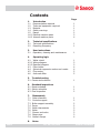
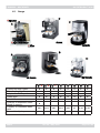
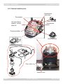
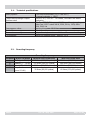
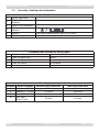
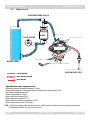
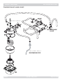
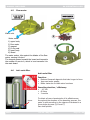
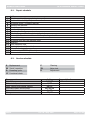
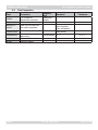
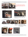
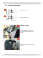
1
Service Manual
Revision 00 May 2010
All parts of this document are the pr
property
roperty of Saeco International Group.
All rights reserved. This document an
and
nd all the information herein is provided without liability deriving from
any errors or omissions. Furthermore, no part may be reproduced, used or collected with the exception
of that authorised in writing or in accordance with a contractual agreement.
Rev. 00 / May 2010
Contents
SAECO
Page
1.
1.1
1.2
1.3
1.4
1.5
1.6.1
1.6.2
Introduction
Documentation required
Tools and equipment required
Material
Safety warnings
Range
External machine parts
Internal machine parts
2.
2.1
2.2
Technical specifications
Technical specifications
Descaling frequency
1
1
3.
3.1
User instructions
Operation, cleaning and maintenance
1
4.
4.1.
4.2.1
4.2.2
4.3
4.4
4.5
4.6
Operating logic
Water circuit
Wiring diagram
Electrical diagram
Filter holder
Spherical cappuccino maker and nozzle
Flow meter
Anti-scale filter
1
3
3
4
4
5
5
1
1
1
1
2
3
4
5. Troubleshooting
5.1. Causes and solutions
1
6.
6.1
6.2
6.3
Standard inspections
Repair schedule
Service schedule
Final inspection
1
1
2
7.
7.1
7.2
7.3
7.4
7.5
7.6
7.7
7.8
7.9
Disassembly
Outer elements
Controls support
Boiler support assembly
Pump
Boiler thermostats
Boiler
Shower and valve
Steam pipe
Oetiker clamps
1
2
2
2
3
3
3
3
4
8.
Notes
Rev. 00 / May 2010
MANUAL MACHINES
CHAPTER 1
INTRODUCTION
SAECO
Rev. 00 / May 2010
MANUAL MACHINES
MANUAL MACHINES
1.1
01 INTRODUCTION
Documentation required
The following documentation is required for repairs:
•
•
Instruction booklet of the specific model
Technical documentation of the specific model (diagrams, exploded drawings)
1.2
Tools and equipment required
Besides standard equipment, the following tools are required:
Qty.
1
1
1
1
1
Description
Screwdriver
Pliers for Oetiker clamps
AC - DC - Vdc tester
Digital thermometer
SSC (Saeco Service Center)
1
1
Allen wrench
Hexagonal spanner
1.3
Scale Limit > 150°C
Programmer
(for programming and diagnosis mode)
Material
Description
Thermal grease
Descaler
Degreaser
Silicone grease
1.4
Notes
Notes
Thermal resistance > 200°C
Saeco descaler
Personal choice
Safe to use with food
Safety warnings
It is recommended to consult the technical manual of the machine before implementing any
operation.
Comply with all applicable standards relating to the repair of household appliances.
Always disconnect the power plug from the mains before beginning repairs on the machine.
Simply turning off the main switch is not sufficiently safe to prevent electrical discharges.
This household appliance is rated as insulation class I.
On completion of the repairs, insulation and dielectric rigidity tests must be performed.
SAECO
Rev. 00 /May 2010
Page 01 / 04
MANUAL MACHINES
1.5.
01 INTRODUCTION
Range
A
B
C
A
Pressurised filter holder
Filter for 1 or 2 coffees
Adaptor for E.S.E. pods
Steam pipe
Steel boiler
Quantity of dispensed coffee
saved in memory
Capacity of removable water
tank
Removable drip tray
SAECO
x
x
x
x
x
C
B
x
x
x
x
x
x
x
x
x
x
x
x
x
x
x
x
x
x
x
x
x
x
x
x
x
x
x
x
x
x
x
x
1.5 l
1.5 l
1.5 l
2.5 l
2.5 l
1l
1.2 l
1.5 l
x
x
x
x
x
x
x
x
x
x
Rev. 00 / May 2010
Page 02 / 04
MANUAL MACHINES
01 INTRODUCTION
1.6.1 External machine parts
Hot water/steam
dispensing knob
ON/OFF switch
Selection
knob
Water tank
Hot water/steam
dispensing pipe
Pressurised
filter holder
Nozzle
Drip tray+grille
Spherical
Cappuccino maker
Some machines have the spherical
cappuccino maker instead of the
nozzle
SAECO
Rev. 00 /May 2010
Page 03 / 04
MANUAL MACHINES
01 INTRODUCTION
1.6.2 Internal machine parts
Overpressure
relief valve
Thermostats
Pump assembly
Hot water/Steam
opening - closing
knob rod
Overpressure
valve
Thermal protector
Boiler assembly
Filter holder ring
Selection knob
SAECO
Rev. 00 / May 2010
Page 04 / 04
CHAPTER 2
TECHNICAL SPECIFICATIONS
SAECO
Rev. 00 / May 2010
MANUAL MACHINES
MANUAL MACHINES
2.1.
02 TECHNICAL SPECIFICATIONS
Technical specifications
Safety system:
2 one-shot thermostats (127°C and 95°C)
1 thermal protector > 184°C
(230/120 V~) 1000 W – for coffee, hot water and steam
dispensing
Ulka Type EP5/S GW approx. 13-15 bar with reciprocating
piston and 120°C cutout 48 W, 230V, 50 Hz, 120V, 60Hz
100V, 50/60 Hz
Opening at approx. 16-18 bar
In tank
Only in the single versions with the coffee amount setting
During the heating phase - approx. 5.6 A
Coffee heat exchanger output:
Stainless steel
Pump
Overpressure valve:
Water filter:
Flow meter assembly
Consumption:
2.2.
Hardness
1
2
3
4
SAECO
Descaling frequency
Water hardness
Soft (up to 7°dH)
Medium (7° - 14°dH)
Hard (15° - 21°dH)
Very hard
(over 21°dH)
Descaling frequency
Without anti-scale filter
240 litres (480,000 pulses)
120 litres (240,000 pulses)
60 litres (120,000 pulses)
With anti-scale filter
480 litres (960,000 pulses)
240 litres (480,000 pulses)
120 litres (240,000 pulses)
30 litres (60,000 pulses)
60 litres (120,000 pulses)
Rev. 00 / May 2010
Page 01 / 01
CHAPTER 3
USER INSTRUCTIONS
SAECO
Rev. 00 / May 2010
MANUAL MACHINES
MANUAL MACHINES
3.1
03 USER INSTRUCTIONS
Operation, cleaning and maintenance
Operating the machine
1
5
6
Fill the water tank
Fill the coffee bean
container
Switch on the appliance
Press to switch on the
machine
Heating
Machine ready
A
B
C
D
E
CLEANING AND TECHNICAL ASSISTANCE
Empty the drip tray
As necessary (float)
Clean the water tank
Weekly
Clean the filter holder
As necessary
Clean the casing
As necessary
Descaling cycle
If signalled
2
3
4
Hardness
1
2
3
4
SAECO
Water hardness
Soft (up to 7°dH)
Medium (7° - 14°dH)
Hard (15° - 21°dH)
Very hard
(over 21°dH)
/
The heating phase begins, wait for it to finish
The machine is ready to dispense beverages
Descaling frequency
Without anti-scale filter
240 litres
120 litres
60 litres
With anti-scale filter
480 litres
240 litres
120 litres
30 litres
60 litres
Rev. 01 / May. 2010
Page 01 / 01
CHAPTER 4
OPERATING LOGIC
SAECO
Rev. 00 / May 2010
MANUAL MACHINES
MANUAL MACHINES
4.1.
04 OPERATING LOGIC
Water circuit
OVERPRESSURE VALVE
PUMP
STOPCOCK
FLOW METER
THERMOSTATS
BOILER
WATER TANK
FILTER HOLDER
DISPENSING COFFEE
HOT WATER/STEAM
DISPENSING PIPE
- COLD WATER
- HOT WATER/STEAM
- HOT WATER
Specifications and requirements
Maximum pump operating pressure 15 bar
Maximum pressure in the water/steam circuit does not exceed 15 bar
Hot water temperature 90°C
Steam temperature 125°C
Max coffee thermostat 95°C
Max steam thermostat 127°C
Max thermal protector thermostat 184°C
Max overpressure valve 16/18 bar
P.S.: Only the single coffee machines have a flow meter, which can set and save the amount
of dispensed coffee via the control board.
SAECO
Rev. 00 / May 2010
Page 01 / 05
MANUAL MACHINES
04 OPERATING LOGIC
Exploded view of a water circuit
PUMP
THERMOSTATS
OVERPRESSURE
VALVE
BOILER
HOT WATER/STEAM
DISPENSING PIPE
SAECO
Rev. 00 / May 2010
Page 02 / 05
MANUAL MACHINES
04 OPERATING LOGIC
4.2.1 Wiring diagram
4.2.2 Electrical diagram
SAECO
Rev. 00 / May 2010
Page 03 / 05
MANUAL MACHINES
4.3
04 OPERATING LOGIC
Filter holder
Standard
filter holder
4.4
Pressurised and mechanical
filter holder
Spherical cappuccino maker and nozzle
HOT WATER/STEAM
PIPE FITTING
STEAM
STEAM
AIR FLOW
ADJUSTMENT
NEEDLE
HOT WATER/STEAM
PIPE FITTING
MILK
FROTHED
MILK
SAECO
STEAM
Rev. 00 / May 2010
Page 04 / 05
MANUAL MACHINES
4.5
04 OPERATING LOGIC
Flow meter
1
A
Water inlet
2
3
Water outlet
1) upper body
2) flow meter
3) magnet
4) O-ring seal
5) lower body
A) Board
4
The water enters, hits against the blades of the flow
meter, causing it to turn.
The magnet passes beneath the board and transmits
the number of revs to it, which in turn transmits it to
the main board
4.6
5
Anti-scale filter
Anti-scale filter
Function:
• Reduced limescale deposits that take longer to form.
• Improved water quality.
• Better taste due to ideal water hardness
Descaling duration / efficiency:
• - 10° dH
• 60 litres
• 2 months
Bypass
SAECO
To obtain a linear characteristic of its effectiveness,
throughout the duration of the descaling process, the
water is split according to the degree of hardness in a
three-phase by-pass (A, B and C).
See small picture.
Rev. 00 / May 2010
Page 05 / 05
CHAPTER 5
TROUBLESHOOTING
SAECO
Rev. 00 / May 2010
MANUAL MACHINES
MANUAL MACHINES
5.1
05 TROUBLESHOOTING
Causes and solutions
FAULT
The machine does not
switch on
POSSIBLE CAUSES
No power supply
SOLUTION
Check the electrical circuit
The thermostats have intervened
Replace the thermostats (if of the
One shot type)
If they are manual, reset them
If they are automatic, they are
reset automatically
Check the electrical connections
The machine does not warm
up
The pump is very noisy
The coffee is too cold
The milk does not froth
The coffee flows too quickly
and does not form the cream
The coffee does not flow or
it flows in drops
The coffee does not flow from
the edges
The power supply does not reach
the boiler
There is no water in the tank
The pump has disengaged from
the supports
The silicone pipe that carries the
water from the tank to the pump is
pinched or blocked
The filter holder is not inserted for
the pre-heating process
The cups are cold
The milk is not suitable (powdered
or skimmed milk)
Dirty nozzle or Cappuccino maker
Little coffee in the filter holder
Grinding level too coarse
There is a missing component in
the filter holder
Grinding level too fine
The coffee is pressed too much in
the filter holder
Too much coffee in the filter holder
Blocked water channels
Blocked filter in the filter holder
The filter holder has been
inserted incorrectly into the coffee
dispensing unit
The upper border of the filter
holder is dirty
The seal of the boiler is dirty or
worn
Too much coffee in the filter holder
Fill the tank
Insert the pump into the supports
once again
Check the water circuit
Run hot water through the filter
holder
Pre-heat the cups with hot water
Use whole milk
Carefully clean the nozzle or the
cappuccino maker with water
Increase the quantity
Use a different mixture
Verify that all the components are
in place and installed correctly
Use a different mixture
Agitate the coffee
Reduce the amount of coffee
Descale the machine
Carefully clean the filter
Insert the filter holder correctly
Clean the edges of the filter holder
Clean or replace the seal
Reduce the amount of coffee
P.S.: Refill the water circuit when the machine is first used as well as when the water in the tank
finishes.
SAECO
Rev. 00 / May 2010
Page 01 / 01
CHAPTER 6
STANDARD INSPECTIONS
SAECO
Rev. 00 / May 2010
MANUAL MACHINES
MANUAL MACHINES
6.1.
1
2
3
4
5
6
7
8
9
10
11
12
13
14
15
16
17
Repair schedule
Action
Visual inspection (damage during transport)
Machine data check (plate)
Functional check / problem analysis
Opening the machine
Visual inspection
Functional tests
Repairing the faults encountered
Checking any modifications (view info, etc.)
Service activities in accordance with the operating schedule
Internal cleaning
Functional test with the machine open
Assembly
Final inspection test
Draining the circuit (in winter)
External cleaning
Insulation test HG 701 (dielectric)
Documentation
6.2.
S
ES
D
CF
06 STANDARD INSPECTIONS
Service schedule
Replacement
Visual inspection
Descaling cycle
Functional check
Component
Water filter
Water tank lip seal
Pipes, fittings and Oetiker clamps
Hot water/steam circuit pump
Water circuit
Wiring
SAECO
P
TR
R
Cleaning
Noise test
Adjustment
Action
P/S/CF
S/CF
ES/CF
ES/TR/CF
D/CF
ES/CF
Rev. 00 / May 2010
Support/tool
Saeco descaler
Page 01 / 02
MANUAL MACHINES
6.3.
Final inspection
Test
Procedure
Coffee
2-3 Coffees for
adjustment purposes
Noise
Amount of
cream
Blow into the cup until
the cream separates
Cream colour
Temperature
Hot water
Steam
SAECO
06 STANDARD INSPECTIONS
Support/
tool
Measuring
beaker
Standard
Tolerance
Standard
The cream should
come together
again completely
Hazel brown
Reading taken while
dispensing
Dispense water
Dispense steam
Thermometer 84 ˚C
Rev. 00 / May 2010
± 4 ˚C
Page 02 / 02
CHAPTER 7
DISASSEMBLY
SAECO
Rev. 00 / May 2010
MANUAL MACHINES
MANUAL MACHINES
7.1.
07 DISASSEMBLY
Outer elements
Remove the water tank, the water drip tray, the grille and the
steam knob.
Upper cover
Loosen the screws as shown on the front and rear
part of the machine
Lift the cover and loosen the screws as shown
RIGHT and LEFT side covers
RIGHT
Remove the side covers by
lifting them upwards
SAECO
LEFT side cover
(note the hooks
of the cover)
RIGHT side cover. Remove the connection of the on/off
switch from the cover
Rev. 00 / May 2010
Page 01 / 04
MANUAL MACHINES
07 DISASSEMBLY
7.2 Controls support
Remove the knob by
pulling it outwards
Remove the electrical connections
and the two bright indicators
Loosen the screws as shown
to remove the rotating switch
7.3 Boiler support assembly
Remove the water connections and loosen the screws as shown
7.4 Pump
Loosen the overpressure valve
SAECO
Remove the pump from the supports
Rev. 00 / May 2010
Page 02 / 04
MANUAL MACHINES
07 DISASSEMBLY
7.5 Boiler thermostats
When putting back the thermostats,
always apply conductive paste for the
thermostat to adhere perfectly to the
boiler
Loosen the screw as shown
7.6 Boiler
Check the internal condition of the boiler
(limescale, any breakages, condition of the
O-ring seal, etc.)
Loosen the screws as shown
7.7 Shower and valve
Loosen the screw as shown
Shower
Loosen the
screw of the
valve holder
7.8 Steam pipe
Check the condition of the
shower, valve holder screw,
channels (holes not blocked)
and verify there is no limescale
on any of the parts
Loosen the screws as shown
SAECO
Rev. 00 / May 2010
Page 03 / 04
MANUAL MACHINES
7.9
07 DISASSEMBLY
Un/installing Oetiker clamps
1
1) Boiler connection
2
2) Other connections
1
Replacing the pipes
1) Use a suitable pair of pliers to
remove the clamp (as shown in the
picture)
2
2) Tighten the clamp as shown in the
pictures
SAECO
Rev. 00 / May 2010
Page 04 / 04
CHAPTER 8
NOTES
SAECO
Rev. 00 / May 2010
MANUAL MACHINES
MANUAL MACHINES
SAECO
08 NOTES
Rev. 00 / May 2010
Page 01 / 01