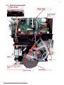
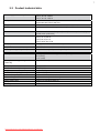
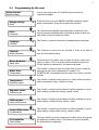
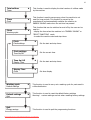
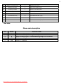
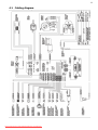
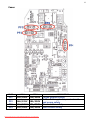
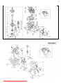
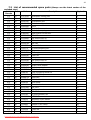
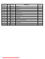
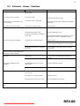
1
Service Manual
Coffe machine
DE DIETRICH
DED700X
The manufacturer declines any responsibility or errors or omissions in this document. No part of the product can be reproduced, used
or copied without prior express written consent or unless this is allowed by a contractual clause.
December 2007 Edition
Downloaded from CoffeeMachineManual.com Manuals
Rev. 00
2
CONTENTS OF THE DE DIETRICH MAINTENANCE MANUAL
1. Introduction Rev 00 from page 3 to page 4
1.1 Appropriate documents
1.2 Tools and equipment
1.3 Safety instructions
2. Technical information Rev 00 from page 5 to page 7
2.1 Internal components
2.2 Product technical data
3. Programming diagnostics and tests Rev 00 from page 8 to page 16
3.1 Programming by the user
3.2 Diagnostics mode
3.3 Test Mode
3.4 Checking micro-switches in Test Mode
3.5 Outages displayed on the screen
3.6 Checking micro-switches and sensors
4. Diagrams Rev 00 from page 17 to page 20
4.1 Cabling diagram
4.2 Hydraulics diagram
5. Operating logic Rev 00 from page 21 to page 26
5.1 Hydraulic operating diagram
5.2 The SBS system
5.3 Aqua Prima
5.4 Fitting and removing OETIKER clamps
6. Fitting and removing components Rev 00 from page 27 to page 41
6.1
6.2
6.3
6.4
6.5
6.6
Removing the upper panel and component support frame
Removing the coffee grinder
Removing the grinding wheels
Removing the coffee grinder motor
Removing the boilers
Replacing the geared motor
7. Exploded views Rev 00 from page 42 to page 47
7.1 Exploded views
7.2 List of recommended spare parts (Check the part numbers with the latest exploded view)
8. Problems - Causes - Solutions Rev 00 from page 48 to page 49
8.1 Problems - Causes - Solutions
Downloaded from CoffeeMachineManual.com Manuals
3
CHAPTER 1
INTRODUCTION
Downloaded from CoffeeMachineManual.com Manuals
REV.00
4
1.1 Appropriate documents
In order to make repairs the following documents must be available:
Instruction notice specific to the model
Technical documents specific to the model (diagrams, exploded views)
1.2 Tools and equipment
The standard set of tools is needed plus the following special items :
1 special screwdriver with a T09 and T10 tip, Pozi Drive type screwdriver and a number 04 hex key.
1 Digital thermometer measuring range =200°C.
It should be usable for measuring liquids and surface temperatures.
1 pair of Oetiker clamp pliers
1 cutting pliers
1.3 Safety Instructions
It is recommended to read the machine’s instruction notice before carrying out any maintenance. Comply
to current standards for repair of household appliances.
Before beginning repairs on the machine, unplug it first. Turning the main power switch off is not
sufficient to avoid all risks of electrocution.
This appliance belongs to isolation class I. Once the repair has been made test its isolation and dielectric
strength.
Downloaded from CoffeeMachineManual.com Manuals
5
CHAPTER 2
TECHNICAL
INFORMATION
Downloaded from CoffeeMachineManual.com Manuals
REV.00
6
2.1 Internal components
Downloaded from CoffeeMachineManual.com Manuals
7
2.2 Product technical data
Power supply and consumption
230 V~; 50 Hz; 1250 W
120 V; 60 Hz; 1250W
100 V; 60 Hz; 1250 W
Safety devices
Coffee boiler 2 175°C safety thermostats – steam boiler 175°C
thermostat and 229°C heat fuse
NTC Sensor
Stainless steel heat exchanger - (1090W), for coffee or hot water.
Temperature control
Coffee resistor
Steam resistor
Aluminium tube heat exchanger - (1000W) for steam production (high
speed steam production)
Pump
Safety relief valve
Ulka vibration pump;
230V; 50 Hz; 48 W
120V; 60 Hz; 41 W
100V; 50/60 Hz; 55 W
Safety pressure relief valve with compensation valve
Water filter
Coffee grinder (grinding wheel)
Placed in the water tank
Threaded brass spindle, ceramic grinding wheels
Motor
Absorption
DC 230 V / 120 V / 100 V
During temperature rise : approx. 4.8 A (230 V);
9 A (120V);
11 A (100V)
Absorption in energy-saving mode
(stand-by)
Approx. 20 Watt/h
Main pump
Dimensions LxWxH (in mm)
Weight
Coffee holder capacity (beans)
pressure 15 bar
595/325/458
Approx. 16 kg
Approx. 300 grams
Water tank capacity
Heat exchanger volume
Water loading time
Temperature rise time
Steam generation
Approx. 2 litres at the maximum level
Approx. 1.0 cm3 (10 ml volume)
Approx 10 seconds at start-up.
Approx. 1.5 minutes.
Immediate
Downloaded from CoffeeMachineManual.com Manuals
8
CHAPTER 3
PROGRAMMING
DIAGNOSTICS AND
TESTS
Downloaded from CoffeeMachineManual.com Manuals
REV.00
9
3.1 Programming by the user
Select product
Machine ready
D On the main page press on the MENU key to access the
programming pages
Press the OK key to go to ENERGY SAVING mode and reduce
power consumption. Press OK to restart the machine
Energy savings
Rince
À
Rince
Language
À
Language
Contrast
À
This function is used to choose the message display language.
Contrast
Water hardness
À
This function is used to set the contrast in order to be able to
view the instructions clearly
Water Hardness
Water filter
À
The hardness of the water used to make the drinks varies from
region to region. This is why the machine should be set to the
correct degree of hardness for the water being used
Water filter
Temperature
À
This function is used to check the water filter (if one is used) by
warning the user when replacement is needed. The
“REINITIALISE” command should be used every time a new filter
is fitted.
Temperature
Expresso aroma
À
This function is used to make warmer or hotter coffee by setting
water temperature (high, medium and low)
Expresso aroma
Coffee aroma
À
This function is used to set the dose of coffee (quantity) to grind
when making an expresso (strong, regular, weak)
Coffee aroma
Large coffee aroma
À
This function is used to set the dose of coffee (quantity) to grind
when making a coffee (strong, regular, weak)
Large coffee aroma
Pre-humidifier
À
This function is used to set the dose of coffee (quantity) to grind
when making a large coffee (strong, regular, weak)
Pre-humidifier
Total coffees
À
The pre-humidifer process increases the coffee aroma thus giving
the coffee an excellent taste. This function is used to humidify
the coffee before preparing it.
The machine automatically eliminates water remaining in the
internal piping immediately after the heating phase so that only
fresh water is used to make the coffee
Downloaded from CoffeeMachineManual.com Manuals
10
Total coffees
Timer
Timer
Clock
À
À
Clock
Washing cycle
À
This function is used to display the total number of coffees made
by the machine
This function is used to save energy when the machine is not
used for long periods. This function is pre-set by the
manufacturer and automatically switches the machine to
ENERGY SAVING mode when the set time has passed.
This function that can be switched on and off by the user can be
used to :
- display the time when the machine is in “ENERGY SAVING” or
“SELECT FUNCTION” mode
- to select the machine start and stop times
Clock
Clock settings
À
Clock settings
Time On/Off
À
Set the current time
Time On/Off
Display Time.
À
Set the start and stop times
Display Time
Clock
À
Washing cycle
Default settings
À
Default settings
Quit
À
Quit
Energy savings
Set the start and stop times
Set time display
This function is used to carry out a washing cycle for parts used in
coffee distribution
This function is used to reset the default factory settings
Warning ! : custom settings are lost when resetting factory settings.
This function is used to quit the programming functions.
Downloaded from CoffeeMachineManual.com Manuals
11
3.2 Diagnostics Mode
SELECT FUNCTION
MACHINE READY
Auto-diagnostic
To go to “diagnostics mode” turn on the machine
is displayed.
Within the first 5 seconds, press the 8-9-8-2 keys in order to display
Programming
energy saving
and then press OK to display
Software
The programming menu is displayed.
Keys “2” and “3” are used to scroll through the settings.
Key “4” is used to change the settings and confirm.
Key “1” is used to quit diagnostics mode.
MACHINE SETTINGS
SETTING RANGE
1
1 Large coffee – 520 impulses
50 – 800
Number of pump impulses to make a large coffee
2
1 Expresso – 170 impulses
50 – 800
Number of pump impulses to make an expresso coffee
3
1 Coffee – 290 impulses
50 – 800
Number of pump impulses to make a coffee
4
Hot Water – 260 impulses
50 - 800
Number of pump impulses to distribute hot water
5
Steam timer 20 seconds
5 - 120
6
K1 Setting K1 Value 8
1 – 50
7
K2 Setting K2 Value 30
1 – 50
8
Normal temperature 90 °C
70 – 130 °C
Normal temperature
9
High temperature 110 °C
70 – 130 °C
High temperature
10
Temperature of the 1st coffee
117 °C
70 – 130 °C
Temperature of the first coffee
11
Total grounds 0
0 – 50
Coffee grounds counter
12
Stop grounds 12
0 - 50
Limit beyond which the coffee grounds tray should be emptied
13
Total water
0
14
De-scaling water ml --
0
15
Water filter ml --
16
H2O after de-scaling message
ml --
0
17
Hot water flow l/h 20
06 - 26
Flow in l/h during hot water distribution
18
Hot water pump settings
62430
Pump settings for water distribution (do not modify the selected
value)
19
Water tank – number of
impulses 0
0
20
Water tank stop – n° of impulses
750
Downloaded from CoffeeMachineManual.com Manuals
FUNCTION
K1 is the temperature rise factor. High value = high factor (do
not modify the selected value)
K2 is the influence of frequency of use on the temperature
setting. High value = low influence (do not modify the selected
value)
Boiler 1 total distributed water (not modifiable)
When the set value is reached the “de-scale” message is
displayed (not modifiable)
Quantity of water filtered since the Aqua Prima filter was
activated
Quantity of water used since the “de-scale” message was
displayed
Water tank counter
Water tank stop
12
21
Number of washing cycles
0
Washing cycle counter
22
Washing cycle status
0
Status of the washing cycle
23
De-scaling - Number
0
Number of de-scaling cycles
24
De-scaling status
0
De-scaling status
25
Phase code
128
26
Last maintenance day
1 - 31
Last maintenance date (day)
27
Last maintenance month
1 - 12
Last maintenance date (month)
28
Last maintenance Year
2000- 2050
Machine status indicator
*
Last maintenance date (year)
* See table
Phase code description
BIT
VALUE
0
3
5
7
1
8
32
128
DESCRIPTION
Fill the machine (not enough water)
Start of coffee cycle. The distribution group is full of coffee
Machine waiting
Il BIT = 1 failure
Downloaded from CoffeeMachineManual.com Manuals
13
3.3
Test Mode
Test mode is used to detect failures more easily and thus reduce the time needed to find them.
SELECT FUNCTION
MACHINE READY
To enter TEST MODE
Auto-diagnostic
To go into “Test mode” switch on the machine,
is displayed, within the next five seconds press
the 10-11-10-11 keys in order.
A series of letters and numbers will be displayed on the next page (see “Checking micro-switches in test mode”
table).
Anti-clockwise rotation of the geared motor
Key 1
Check the anti-clockwise rotation of the geared motor and the rise of the coffee group. Check the noise made by the
geared motor.
When the geared motor is in distribution position the figure 1 should display on the top line.
Clockwise rotation of the geared motor
Key 2
Check the clockwise rotation of the geared motor and the descent of the coffee group. Check the noise made by the
geared motor. When the geared motor is on standby the figure 2 should display on the top line.
Coffee grinder operation
Key 3
Check the coffee grinder rotates anti-clockwise. Check the noise made by the coffee grinder.
(keep pressing until the grinder stops automatically). If the grinder motor is running, a reference value for the number of
revs. is shown (approx. 6-12) on the lower right side of the display and the figure 9 starts flashing on the top line.
Water – steam solenoid valve operation
Key 3 + 7
Check that the pump is working correctly and check the noise it makes. During water distribution check that the turbine
is working correctly (the flow in litres/h is shown at the bottom right side of the display)
Water – steam solenoid valve operation
Check that the solenoid valve is working correctly
Downloaded from CoffeeMachineManual.com Manuals
Key 2 + 7
14
Pressured up pump operation
Key 1 + 7
To check that the pump is pressured up. (this is done to check for eventual leaks inside the machine)
Steam boiler electric current
Key 4 + 6
Check the electric current using an ammeter.
During the temperature rise approx. :
4.8 A (230 V);
9 A (120V);
11 A (100V)
Coffee boiler electric current
Key 2 + 6
Check the electric current using an ammeter.
Boiler temperature
Key 4 + 6 + 7
This function is used to check the current temperature of the coffee boiler
Contrast LCD Key 1 + 6 + 7
Back-light LCD Key 2 + 6 + 7
3.4
Display
N°
1
2
3
5
6
7
8
9
0
A
M
R
K
0-8
*
Checking micro-switches in Test Mode
Micro-switch
Geared motor in distribution
phase switch
Geared motor on standby
switch
Panel switch
Coffee ground tray and drip
tray switch
Coffee group switch
Door switch
Turbine sensor
Coffee grinder sensor
Water sensor
Water tank safety sensor
No Coffee
RTC control
Facade detector
Coffe grinder setting
Coffee grinder impulses
Function
It sets the stopping point of the group’s rise
It sets the stopping point of the group’s descent
Detects the presence of the coffee grounds tray and the drip tray
Detects the presence of the coffee group
Detects the correct shutting of the door
Counts the turbine impulsions in order to define the quantity of water to
be used when making the coffee
Defines the number of revolutions depending on the dose of coffee
Detects when there is insufficient water in the tank
Detects when the water tank is full
Detects when there is no more coffee in the coffee holder
Detects correct function of the clock (it should blink)
Detects the presence of the facade
Detects the coffee grinder settings in factory control phase
Indicates whether the value on the previous line (0-8) was saved
Downloaded from CoffeeMachineManual.com Manuals
15
3.5
Outages displayed on the screen
GSI (water supply outage)
-
CAUSES/SOLUTIONS
Internal drip tray sensor
Power
PURGE
-
Run water
Check the water tank is correctly installed
GROUP BLOCKED
-
Replace upper / lower micro-switch
Power
Small geared motor
-
Close the front panel
Micro-switch
Earthing of the machine disrupts the micro-switch
Cut cables
DISPLAYED OUTAGES
CLOSE THE PANEL
-
CLOSE THE DOOR
-
Close the front panel
Micro-switch
TRB support unhooked
Door hinge bent
Cut cables
COFFEE GROUNDS TRAY MISSING
-
Put the coffee grounds tray back
Micro-switch
Cut cables
GROUPE MISSING
-
Put the group back
Micro-switch
Group flange broken
Cut cables
NOT ENOUGH COFFEE
-
Add coffee
Replace PW
Replace coffee griinder sensor
DESCALE
-
Descale
Replace CPU
GRINDER BLOCKED
-
Replace the coffee grinder
Replace PW
FILL WATER TANK
-
Jammed floater
Replace water sensor
Replace PW
FLASHING DISPLAY
-
Replace CPU
Replace PW
Crushed cables
WAIT (does not heat) heat LEDs off
-
Reinitialise the thermostats
Boiler cable disconnected
Replace PW
PART OF THE DISPLAY MISSING OR
DISTORTED
-
Replace the display
Replace CPU
NO STEAM
-
Replace steam boiler
Replace PW
Downloaded from CoffeeMachineManual.com Manuals
16
3.6
N°
1
Checking micro-switches and sensors
Description
Geared motor microswitch WORK
Geared motor microswitch HOME
Front command strip
micro-switch
Activated
Distributor in WORK
position
Distributor in HOME
position
Command strip closed
Deactivated
Distributor not in
WORK position
Distributor not in
HOME position
Command strip
open
COFFEE GROUNDS TRAY
micro-switch
DISTRIBUTION GROUP
micro-switch
Tray present
Tray absent
Present
Absent
7
8
DOOR Micro-switch
FLOW METER
Door closed
Door open
9
COFFEE GRINDER
IMPULSES
0
WATER LEVEL in the
tank
WATER ALARM microswitch
Level is OK
Level is LOW
Water detected in the
bottom of the machine
M
Coffee holder empty
There is no coffee
No water detected
in the bottom of the
machine.
There should be
coffee.
R
CLOCK (shows seconds)
Even seconds
Odd seconds
K
FRONT FACE PRESENT
Present
Absent
0-8
COFFEE GRINDER
SETTINGS
COFFEE GRINDER
SETTINGS SAVED
2
3
5
6
A
*
Notes
The technician
can check the
impulses
The technician
can check the
impulses
This is derived
and not
hardware data.
It should flash at
1 HZ
Factory settings
Not saved
Downloaded from CoffeeMachineManual.com Manuals
Saved
17
CHAPTER 4
DIAGRAMS
Downloaded from CoffeeMachineManual.com Manuals
REV.00
18
4.1 Cabling diagram
Downloaded from CoffeeMachineManual.com Manuals
19
Fuses
FUSE
120 V
230V
PF1
02A/250V 01A/250V
PF2
16A/125V 08A/250V
PF3
PF4
16A/125V 08A/250V
02A/250V 02A/250V
Downloaded from CoffeeMachineManual.com Manuals
DESCRIPTION
Coffee grinder safety
Coffee boiler, grinder, main circuit
and pump safety
Steam boiler safety
Main circuit safety
20
4.2 Hydraulics diagram
Downloaded from CoffeeMachineManual.com Manuals
21
CHAPTER 5
OPERATING LOGIC
Downloaded from CoffeeMachineManual.com Manuals
REV.00
22
5.1 Hydraulics operating diagram
n°
Component
Function
1
Water tank
Water supply
2
Floater
Water shortage detection
3
Water filter
Elimination of solid matter from the water
4
Turbine
Measures flow per impulse, sets quantities
5
Pump
Water flow / pressure
(15 bar)
6
Pressure safety valve
Protects the circuit from over pressuring (opens at 17-19 bars)
7
Heat exchanger / heater
Heats for water, coffee, steam distribution.
8
Temperature sensor
Transmits current temperatures to the electronics
9
Overheating thermostat
Switches off the machine in the event of overheating
10
Hot water – steam tap
When open supplies hot water or steam
11
Tube boiler
For steam distribution
12
Frother nozzle valve
Opens if the nozzle obstructs
Downloaded from CoffeeMachineManual.com Manuals
23
5.2 The SBS system
Distribution Process
The SBS distribution system (see figure 2) can be set using a button and is used to change (by increase
or decrease depending on the position of the button) the flow of water into the group for percolation.
Thus the percolation time can be varied (extraction time) and, consequently, the intensity of the flavour,
while keeping the coffee smooth.
Function
When the SBS valve is open coffee accumulates inside the membrane valve due to a weak counter
pressure from the SBS valve. The valve needle thus remains in its maximum open position due to the
resistance of the spring. The coffee flows quickly (see figure 3). When the SBS valve is closed, coffee
accumulates on the valve membrane and increases the pressure inside the valve. The spring releases due
to the counter pressure and the valve needle reduces the flow of coffee (see figure 4).
Fig 1
Fig.3
Downloaded from CoffeeMachineManual.com Manuals
Fig.2
Fig.4
Downloaded from CoffeeMachineManual.com Manuals
25
Checking SBS valve operation
To check that the SBS valve is working correctly, make a large coffee. While the coffee is preparing check
the difference in distribution speed between the maximum position and the minimum position.
The difference in speed is 2.5 times faster (therefore the difference is VERY obvious !!).
LIGHT
EXPRESSO
Downloaded from CoffeeMachineManual.com Manuals
SHORT
26
5.3 Aqua Prima
Operating logic with “AQUA PRIMA” filter
If the use of the “aqua prima” filter is selected from the user menu or the command strip, the system’s
water measuring logic becomes the following :
If the “aqua prima” function is active the electronics will count one turbine impulse every two
revolutions.
If the “aqua prima” function is inactive the electronics will count turbine impulses one impulse per
revolution. A graph showing this function is shown below:
DESCALING
Hardness
1
Water hardness
Descaling frequency
Descaling frequency
when using Aqua Prima
Approx. 3 months 120 litres
Approx. 3 months 240 litres
Approx. 2 months 90 litres
Approx. 2 months 180 litres
3
Soft water (jusqu’à 7ºdH)
Standard water
(7º-14ºdH)
Hard water (15º-21ºdH)
Approx. 6 weeks 60 litres
Approx. 6 weeks 120 litres
4
Hard water (15º-21ºdH)
Approx. 4 weeks 30 litres
Approx. 4 weeks 60 litres
2
Downloaded from CoffeeMachineManual.com Manuals
Downloaded from CoffeeMachineManual.com Manuals
28
5.4 Fitting and removing OETIKER clamps
Fitting the clamp on the boiler
BOILER
The figure (1) shows where the clamp should be mounted on the boiler joint.
To tighten the clamp use the appropriate pliers. Make
sure it is sufficiently tight (A) and that it is in the right
place (1)
To remove the clamp proceed as illustrated (B)
Downloaded from CoffeeMachineManual.com Manuals
29
CHAPTER 6
FITTING AND
REMOVING
COMPONENTS
Downloaded from CoffeeMachineManual.com Manuals
REV.00
30
6.1 Removing the upper panel and component support frame
Remove the screws indicated
at the rear of the machine
Remove the upper panel as
illustrated
Cut the “B” clamp, remove the “A” connector
and the “C” terminal connectors
Remove the indicated screws on the
LEFT and RIGHT sides
Downloaded from CoffeeMachineManual.com Manuals
31
Remove the screws shown on the front area and detach the steam pipe
by removing the indicated clip
Lift the component support frame
Chassis
Downloaded from CoffeeMachineManual.com Manuals
Board
32
Remove the indicated screws
Cut the clamp
Remove the cabling and then the upper board
by lifting it
Downloaded from CoffeeMachineManual.com Manuals
33
6.2 Removing the coffee grinder
Remove the screws indicated by an arrow
(Note. when refitting the coffee grinder do not
forget the two “2” that go around the motor
“3”)
Remove the coffee grinder
When refitting the coffee grinder take care to
correctly place the indicated joint
Downloaded from CoffeeMachineManual.com Manuals
34
6.3 Removing the grinding wheels
To remove the upper grinding wheel “A”
(Unpack) turn it anti-clockwise as shown in the
first picture using the “B” ring until the “C” tool is
opposite the “D” aperture.
(removing the upper grinding wheel)
Once freed, the grinding wheel can be removed from its support.
Downloaded from CoffeeMachineManual.com Manuals
35
(removing the lower grinding wheel)
Clean out all coffee residue using a small flat
screwdriver, compressed air or a vacuum cleaner.
Turn the grinding wheel anti-clockwise while levering
it using a small flat screwdriver as shown in the first
picture.
Once freed, the lower grinding wheel can be
removed from its support.
The upper and lower grinding wheels are
made from ceramic and are completely
identical.
Note :
to refit them proceed in the opposite
order
Downloaded from CoffeeMachineManual.com Manuals
36
6.4 Removing the coffee grinder motor
Remove the screws of the grinder motor side-plate.
Remove the sensor from the side-plate by
pressing on the anchor tab.
Remove the sensor from its casing in the side plate
using a small screwdriver (as shown above)
Disconnect the motor power cables.
Remove the rubber cap from the motor side-plate.
Downloaded from CoffeeMachineManual.com Manuals
37
If the crown is damaged, remove the cog wheel using a
size 10 and a size 7 spanner to unscrew the fixing nut.
Fit the new crown by placing it on the spindle gear and
fix it by fitting the washer and fixing nut.
Block the nut on the brass spindle axis using the size 7
and 10 spanners.
Grease the entire crown.
Downloaded from CoffeeMachineManual.com Manuals
38
Evenly spread grease on the entire surface of the cog
wheel.
Apply grease to the teeth of the endless screw on the
grinder motor shaft.
Fit the motor side-plate as illustrated.
Fit the fixing pins as illustrated and push them right
into their housing.
Downloaded from CoffeeMachineManual.com Manuals
39
6.5 Removing the boilers
Steam boiler
Remove screw “A” and the two “B” clamps, remove the two silicone meshed pipes.
Remove the resistance protection cover “C” and disconnect the two “D” connectors.
To remove the steam boiler, cut the two
clamps and disconnect the two silicone pipes
Downloaded from CoffeeMachineManual.com Manuals
40
Coffee boiler
Remove the screw as shown
Remove the small cover and the indicated
screws to free the boiler pivot
To remove the coffee boiler remove the three
screws as shown above.
Disconnect the connector shown by the arrow
Remove the boiler from its casing.
Downloaded from CoffeeMachineManual.com Manuals
41
Remove the fixing pin and disconnect the
teflon pipe that connects the pump to the
boiler by removing the clamp
This picture shows the coffee boiler once removed
from the casing.
To replace the thermostats, remove the
indicated screw (this can also be done while
the boiler is still in its casing)
To remove the boiler from its base unscrew the
indicated screw (A)
Downloaded from CoffeeMachineManual.com Manuals
42
6.6 Replacing the geared motor
Remove the casing (A) by
removing the three screws.
Remove the two screws and the
boiler pivot (B)
Remove the protection cover (C) by removing the
screws.
Inside the area protected by the casing are :
- the electric motor (A) with the transmission
and synchronisation gears (B) and (C) for
the distribution group;
- the coffee grounds tray micro-switch (D);
- the distribution group micro-switch (E);
- the distribution group standby detection
micro-switch (F);
- the distribution group, distribution
detection micro-switch (G);
Remove the gear (C) that is coupled to the shaft
of the small motor. Remove the larger gear (B).
Pull out the small motor (A) and its transmission
shaft (H).
Downloaded from CoffeeMachineManual.com Manuals
43
Fit the small motor and transmission shaft by placing the parts in their casing (L)
Fit the gear (B), while making sure
that the printed arrow is included in
the opening that contains the pivot
(P).
Refit the protection cover (C)
and replace the screws
Fit the gear that couples with the
transmission shaft.
Refit the boiler pivot (B) while making sure that the
two joints (G) are present on the beak that fits in the
pipe hole (D).
Replace the boiler pivot screws.
Warning : before tightening the screws they
must both be fully screwed
Downloaded from CoffeeMachineManual.com Manuals
44
CHAPTER 7
EXPLODED VIEWS
Downloaded from CoffeeMachineManual.com Manuals
REV.00
45
7.1 Exploded view
Downloaded from CoffeeMachineManual.com Manuals
46
Downloaded from CoffeeMachineManual.com Manuals
47
Esp. E90046
Downloaded from CoffeeMachineManual.com Manuals
48
7.2 List of recommended spare parts (Always use the latest version of the
exploded view)
N°
Pos.
Planche
2/5
2/5
2/5
2/5
2/5
2/5
2/5
2/5
2/5
2/5
2/5
2/5
3/5
3/5
3/5
3/5
3/5
3/5
3/5
3/5
3/5
3/5
3/5
3/5
3/5
3/5
3/5
4/5
4/5
4/5
4/5
4/5
4/5
4/5
4/5
4/5
4/5
4/5
4/5
4/5
05
09
10
11
12
13
14
15
19
25
40
43
02
03
19
20
21
24
26
27
28
29
37
42
43
44
47
05
06
07
08
10
17
19
20
27
28
32
38
40
Code
227370303
145853260
149501550
229186103
145854962
149206750
126839418
147895450
140329162
140326661
140324461
140320762
11004398
11001170
147923662
229434700
224640200
147923762
140324362
147660562
145856562
126764718
186053700
11006792
12000440
145898750
11009545
12000140
11001164
140321961
229452100
140328059
11001163
189428300
11004555
11003342
12000892
NF11.052
11003559
NV99.099
Description
Distributor moving part
Gaco Joint
Distribution pipe
Distributor support
Joint
Push button mount
Push button spring
Push button for the door
OR 117
OR metric 0040-20
OR metric 0060-20
OR 108
Power Card
2 pole connecting set
Connection for water valve
Teflon pipe
Filter set
Adapter
OR metric 0060-30
Small valve piston
Water valve adapter
Cylinder spring
Switch
CPU connecting board set
PUSH-PUSH key
Male part
2 flat cable sets
Ulka pump
Connector set
OR 2031
Safety valve set
OR 2015
2 pole connector set
175° C Thermostat
Bleckman 230V resistor
Solenoid valve
Oetiker D 9.5 clamp
Oetiker clamp
Cable set
Turbine set
Downloaded from CoffeeMachineManual.com Manuals
Qty in %
3
10
3
3
5
3
3
3
10
10
10
10
3
3
3
3
5
3
10
5
10
5
3
3
5
5
3
3
3
10
3
10
3
3
3
3
10
10
5
3
49
N°
Planche
4/5
4/5
4/5
4/5
4/5
4/5
5/5
5/5
5/5
5/5
5/5
5/5
5/5
5/5
Pos.
47
49
50
54
56
57
04
14
42
43
44
51
53
56
Code
11005060
NM01.035
NM01.057
189428600
11001522
11006731
146520100
11004354
NE05.038
9121.042
9121.042
11003037
186724200
11003426
Description
Pivot set
OR 0090-20
OR 0050-20
175° C Thermostat
NTC temperature sensor
230V boiler set
48x28 ceramic grinding wheel
Coffee grinder set
Micro-switch
Z 108 gear
Z 12/90 gear
Motor set for geared motor
Micro-switch
Coffee group
Downloaded from CoffeeMachineManual.com Manuals
Qté
en %
5
10
10
3
3
3
3
3
5
3
3
3
3
3
50
CHAPTER 8
PROBLEMS CAUSES
SOLUTIONS
Downloaded from CoffeeMachineManual.com Manuals
REV.00
51
8.1 Problems - Causes - Solutions
Problems
Causes
Solutions
The machine will not power up
The machine is not connected to a
power outlet
Have the mains connection checked
The coffee is not hot enough
The cups are cold
The machine is not distributin g hot
water or steam
The coffee is served too slowly
The steam nozzle is obstructed
The coffe is too finely ground
Warm the cups with hot water
Remove the steam nozzle by pulling it downwards
and clean it.
Change the mix
Turn the grinder setting button to a higher setting
The distribution group is dirty
The SBS system button is completely
to the right
The coffee is served too quickly
The coffee is too coarsely ground
Wash the distribution group
Turn the button to the left and then turn it to the
right when the machine is distributing coffee
Change the mix
Turn the grinder setting button to a lower setting
The machine takes to long to heat up
and the quantity of water distributed
through the nozzle is limited
The distribution group cannot be
removed
The SBS system button is completely
to the left
Turn the button to the right when the machine
serves coffee
There is scale in the machine circuit.
Carry out a de-scaling cycle
The distribution group is not in the
right position.
Turn on the machine. Close the front panel; the
group returns to its initial position and can be
removed.
Remove the drip tray.
The drip tray is fitted
The coffee is spilling from the
distributor
The coffee does not froth
Water is overflowing from the drip
tray
The distribution group is not in the
right position
Place the distributor correctly
The distributor is blocked up
Remove the distributor and clean it
The mix is not suitable or was roasted
too long ago
Change the coffee mix.
The coffee is too coarsely ground
Adjust the grinder
The SBS button is turned to the left
Turn the SBS button to the right
The drip tray is full
Check the floater position and empty the drip tray
Downloaded from CoffeeMachineManual.com Manuals
REV.00