1
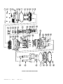
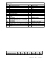
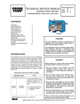
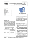
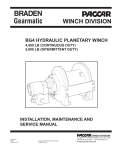
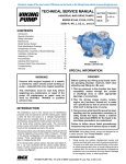
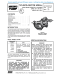
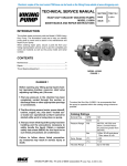
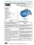
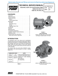
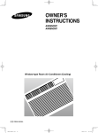
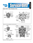
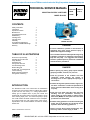
Electronic copies of the most current TSM issue can be found on the Viking Pump website at www.vikingpump.com
TECHNICAL SERVICE MANUAL
SECTION
TSM 270
INDUSTRIAL ROTARY LOBE PUMP
PAGE
1 of 10
Model RL41507
ISSUE
F
CONTENTS
Safety Information
Introduction
Special Information
Maintenance
Suggested Repair Tools
Disassembly
Cartridge Seal
Labyrinth Seal
Assembly
Thrust Bearing Adjustment
Installation of PEEK® Bushings
Warranty
1
1
4
4
5
5
6
7
7
8
9
12
TABLE OF ILLUSTRATIONS
RL41507 Pump Assembly
Exploded Pump Parts View
Pump Rotation
Head Removal
Timing Gear Removal
Use Of Bearing Puller Bracket Removal
Fluidtec P/S®-II Cartridge Seal
Lobe Positioning
Bearing Housing Assembly Timing Gear Positioning
1
2
4
5
5
6
6
6
7
7
7
INTRODUCTION
The illustrations used in this manual are for identification
purposes only and cannot be used for ordering parts. Obtain
a parts list from the factory or a Viking representative.
Always give a complete name of part, part number and
material with the model number and serial number of pump
when ordering repair parts. The unmounted pump or pump
unit model number and serial number are on the nameplate.
This manual deals only with Viking Rotary Lobe Pumps.
Specifications and recommendations are listed in Catalog
Section 270.
PEEK® is a trademark of Victrex PLC.
FIGURE 1
MODEL RL41507
DANGER!
Incorrect installation, operation or maintenance of
equipment may cause severe personal injury or
death and/or equipment damage.
This information must be read fully before beginning
installation, operation or maintenance and must be
kept with the pump. It is suggested that suitably
trained or qualified persons perform all installation
and maintenance procedures.
DANGER !
Before opening any Viking pump liquid chamber
(pumping chamber, reservoir, etc.) be sure:
1.
That any pressure in the chamber has been
completely vented through the suction or
discharge lines or other appropriate openings or
connections.
2.That the driving means (motor, turbine, engine, etc.)
has been “locked out” or made non-operational so
that it cannot be started while work is being done
on pump.
3.That you know what liquid the pump has been
handling and the precautions necessary to
safely handle the liquid. Obtain a material safety
data sheet (MSDS) for the liquid to be sure these
precautions are understood.
4.That the timing gearbox to cool before handling the
pump. The oil will become very hot during normal
operation. Allow the timing gearbox oil.
Failure to follow above listed precautionary measures may result in serious injury or death.
VIKING PUMP, INC. • A Unit of IDEX Corporation • Cedar Falls, IA 50613 USA
figure 2 Exploded parts view
SECTION TSM
270
ISSUE
F
PAGE 2 OF 10
TABLE 1 RL41507
ITEM
1
2
3
4
5
6
7
8
9
10
11
12
13
14
15
16
17
18
19
20
21
22
23
DESCRIPTION
Magnetic Drain Plug for Gear Case
Capscrew for Gear Cover
Lipseal for Gear Box Cover
Breather
Gear Case Cover
Sight Glass
Gear Case Cover or Head O-ring
Locknut TN-14, (2 Req’d)
Lockwasher TN-14, (2 Req’d)
Timing Gear for Driver Shaft
Timing Gear for Driven Shaft
Key, Special
Capscrew for Bearing Housing Assembly, (12 Req’d - 6 for each
Bearing Housing Assembly)
Lockwasher for Bearing Housing Assembly, (12 Req’d - 6 for
each Bearing Housing Assembly)
Outer Bearing Spacer, (2 Req’d - 1 for each Bearing Housing
Assembly)
Lipseal for Bearing Housing, (4 Req’d - 2 for each Bearing
Housing Assembly)
Endcap for Bearing Housing, (2 Req’d - 1 for each Bearing
Housing Assembly)
Double Tapered Roller Bearing, (2 Req’d - 1 for each Bearing
Housing Assembly)
O-ring for Bearing Assembly, (2 Req’d - 1 for each Bearing
Housing Assembly)
Bearing Housing, (2 Req’d - 1 for each Bearing Housing
Assembly)
Labyrinth Seal, (2 Req’d - 1 for each Bearing Housing Assembly)
Inner Bearing Spacer, (2 Req’d - 1 for each Bearing Housing
Assembly)
Bearing Housing Assembly, Includes Items 13-22, (2 Req’d)
ITEM
24
25
26
28
29
30
31
32
33
34
35
36
37
DESCRIPTION
Dowel Pin, (5 Req’d)
Bracket
Nut 1/2” NC for Bracket, (8 Req’d)
Setscrews for Bearing Housing, (4 Req’d)
Pipe Plug for Bearing Housing, 1/8”, (4
Req’d)
Capscrew for Seal, 5/8”, (8 Req’d)
Cartridge Lipseal, (2 Req’d)
1/2” Stud for Bracket, (8 Req’d)
Lifting Eye
Casing/Bushing Assembly
5/8” Stud for Head, (18 Req’d)
½” Pipe Plugs, to Casing, (4 Req’d)
Casing Bushings (2 Req’d)
38
Lobe/Shaft Assembly, Driver
39
Lobe/Shaft Assembly, Driven
40
Head/Bushing Assembly
41
Nut, 5/8” for Head, (18 Req’d)
42
Pipe Plug, 1/4”, to Head (2 Req’d)
47
Lockwasher for Seals, (8 Req’d)
61
64
not
illus.
not
illus.
Washer for Seals, (8 Req’d)
Bushings for Head, (2 Req’d)
Pipe Plug 1/8”, (2 Req’d), see page 2
Bearing Housing Spanner Wrench
TABLE 2 Torque Specifications
Item Number
2
8
13
26
28
30
41
RECOMMENDED TORQUE (ft-lb)
75
600
18
75
8 (100 in-lb)
15
75
SECTION TSM
270
ISSUE
F
PAGE 3 OF 10
SPECIAL INFORMATION
DANGER !
Before opening any Viking pump liquid chamber
(pumping chamber, reservoir, etc.) be sure:
1.
That any pressure in the chamber has been
completely vented through the suction or
discharge lines or other appropriate openings or
connections.
2.That the driving means (motor, turbine, engine,
etc.) has been “locked out” or made nonoperational so that it cannot be started while work
is being done on pump.
3.That you know what liquid the pump has been
handling and the precautions necessary to
safely handle the liquid. Obtain a material safety
data sheet (MSDS) for the liquid to be sure these
precautions are understood.
4.That the timing gearbox to cool before handling
the pump. The oil will become very hot during
normal operation. Allow the timing gearbox oil.
Failure to follow above listed precautionary
measures may result in serious injury or death.
ROTATION
Refer to figures 2 and 2a. Viking RL pumps operate equally
well in either clockwise and counterclockwise rotation.
Rotation is determined by viewing the pump from the shaft
end. There are two tapped holes in each port to vent the seal
chambers. 1/8” pipe plugs are installed on the discharge side
of the pump and the holes on the suction side are left open.
Standard factory build is clockwise rotation. Pipe plugs must
be switched to the opposite port if rotation is reversed.
DISCHARGE
SUCTION
CW
PRESSURE RELIEF VALVES
An integral pressure relief valve is not available on this
pump. Viking Industrial Rotary Lobe pumps are positive
displacement pumps and must be provided with some sort of
pressure protection. An inline pressure relief valve, a torque
limiting device or a rupture disk must be provided in the
pumping system.
MAINTENANCE
Series RL pumps are designed for long, trouble-free service
life under a variety of application conditions with a minimum
of maintenance. The following points will help provide long
service life.
LUBRICATION
CAUTION:
Pumps are supplied without gear case oil. Be sure
to add the proper amount and type of lubricant before operating the pump. Do not overfill!
GEAR CASE - Use a grade of gear lube oil with EP (Extreme
Pressure) additive for the ambient temperature range.
EP150
EP220
EP320
0 - 32° F
32 – 85° F
above 85° F
Remove oil breather (Item #4) and add 3 Qt. of the specified
lubricant. Fill to center of sight glass (Item #6).
After 100 hours of operation, drain and refill with new lubricant
and clean off the magnet in the drain plug (Item #1).
Check lubricant level regularly and add lubricant as
necessary. Drain and refill with new lubricant every 12
months or 3000 hours of operation, whichever comes first
TAPERED ROLLER BEARINGS
Pumps supplied from the factory are packed with heavyduty grease. Upon disassembling the bearing housing, the
bearings should be cleaned and repacked with heavy-duty
multi-purpose grease.
BUSHINGS
The bushings used in this pump are lubricated with the
product and do not require any external source of lubrication
during operation.
CLEANING THE PUMP
Keep the pump as clean as possible to facilitate inspection
and repair work.
FIGURE 2
STORAGE
If a new pump is to be stored or not used for six months or
more, add 5 oz. of non-detergent SAE 30 weight oil in the
timing gear box. Viking suggests rotating the pump shaft
by hand one complete revolution every 30 days to circulate
the oil.
FIGURE 2a
SECTION TSM
270
ISSUE
F
PAGE 4 OF 10
SUGGESTED REPAIR TOOLS
The following tools must be available to properly repair
Viking RL pumps. These tools are in addition to standard
mechanics’ tools such as open end wrenches, pliers, screw
drivers, etc. Most items can be obtained from an industrial
supply house.
1.
2.
3.
4.
5.
6.
7.
8.
Soft headed hammer
Allen wrenches
Depth micrometer (0-1” Range)
Bearing Locknut Spanner Wrench (Source: #472
J.H. Williams & Co. or equal)
Brass bar or wood block
Arbor Press
3/4” NC X 6” capscrews (2)
Bearing Puller PUMP DISASSEMBLY
DANGER !
Before opening any Viking pump liquid chamber
(pumping chamber, reservoir, etc.) be sure:
1.
That any pressure in the chamber has been
completely vented through the suction or
discharge lines or other appropriate openings or
connections.
figure 3
4.Straighten out the bearing lockwasher tab on both shafts
(See figure 4). Place a wooden block or brass bar in
between the lobes to block rotation of the top shaft.
Use the spanner wrench (Suggested Repair Tools # 5)
to loosen the locknut. Remove the wooden block and
insert on the opposite side to restrict movement of the
other shaft. Remove the second locknut. Remove both
of the lockwashers.
Bearing Lockwasher Tabs
2.That the driving means (motor, turbine, engine,
etc.) has been “locked out” or made nonoperational so that it cannot be started while work
is being done on pump.
3.That you know what liquid the pump has been
handling and the precautions necessary to
safely handle the liquid. Obtain a material safety
data sheet (MSDS) for the liquid to be sure these
precautions are understood.
4.That the timing gearbox to cool before handling
the pump. The oil will become very hot during
normal operation. Allow the timing gearbox oil.
Failure to follow above listed precautionary
measures may result in serious injury or death.
1.Turn the centering tabs on the seals 90° (See Figure 8).
2.Remove the (18) nuts holding the head with a 15/16”
wrench. Carefully slide head off of studs. If head does
not slide freely, insert a dowel pin approx. 1” long into the
¾” tapped holes (one at the top and bottom) then thread
in the ¾” X 6” capscrews (suggested repair tools #2).
CAUTION: The head weighs 125 pounds and will require
two people to handle. See Figure 3.
3/8” Jackscrew Holes
figure 4
5.Slide the timing gears off the shafts. If the timing gears
do not come off easily, use (3) 1/2“ capscrews as
jackscrews or a bearing puller (See Figure 4).
6.Remove the keys under the gears. (These are special
size keys – do not lose them - standard 5/8” key stock
should not be used)
7.Remove the (4) 1/8”allen head pipe plugs (items #29) on
the sides of the bracket. Loosen the (4) 5/16” set screws
(items #28) that lock the bearing housings in place by 3
full turns.
8.Use the assembly tool shown in Figure 5 to rotate and
remove the bearing housing. The bearing housing
should come out as an assembly. If it does not, remove
the (6) allen head capscrews (Item #13) then the end
cap (Item #17). Slide the outer spacer off the shaft.
3.Drain oil in the gear case by removing the pipe plug (item
#1). Remove (6) ½ “ capscrews then carefully slide gear
case off driver shaft. There is one dowel pin that might
restrict removal.
SECTION TSM
270
ISSUE
F
PAGE 5 OF 10
12.Depending on the type of mechanical seal used, make
sure the securing devices to hold or stabilize the
seal while removing from the shaft are in place and
positioned properly. Unlock the setscrews securing the
sleeve to the shaft. Remove the (4) capscrews that hold
each seal in place then pull the seal off the shaft.
figure 5
Bearing Housing Spanner Wrench
Part No. 2-810-060-375
13.The lobe and shaft assembly is now ready to pull out of
the casing.
Caution: This assembly weighs 130 pounds and requires
two people or an overhead hoist to handle.
9.Remove the outer cone of the tapered roller bearing. It
might be necessary to thread the bearing housing back
into the bracket. Remove the spacer between the two
cones and the cup of the bearing set.
14.Slide the driver shaft out 10” and have one person
support the assembly. Continue sliding the assembly
out with the other person supporting the opposite end of
the shaft. Repeat these steps for the driven shaft.
CAUTION: It is important to keep the bearing together as
a set and in the proper order since the spacer is ground
specifically for those components to provide the proper
preload.
15.Inspect the labyrinth seals (Item #21) and lip seals in
each bearing housing. Leave in the housing unless
they show signs of wear or damage (See LABYRINTH
SEAL, page 7).
10.Remove the inner bearing cone, if it doesn’t slide freely,
reinstall the end cap and capscrews and use a puller
(see figures 6 and 10). The back side of the end cap has
a machined recess to allow puller usage. Slide the inner
spacer (Item #22) off shaft. Repeat the process for the
other bearing housing.
16.Clean all parts thoroughly and examine for wear or
damage. Check the lip seals, bearings, bushings and
replace if necessary. Check all other parts for nicks,
burrs or excessive wear and replace if necessary.
Pay special attention to the shaft area underneath the
mechanical seal where seal set screws contact.
CAUTION: Do not mix the two bearing cones with
respect to the one piece cup.
17.Wash bearings in clean solvent and blow out with
compressed air. Make sure bearings are clean, then
lubricate with light oil. Check for roughness by placing
the cone on the cup and turning.
figure 6
CARTRIDGE SEALS
11.Reposition the pump so the bracket is free standing. See
figure 7. Place a lifting strap through the top bearing
bore and support from overhead. Remove the (8) ½”
nuts (Item #26) then remove the bracket. Pull the
bracket off of the dowel pin and studs.
figure 8
The standard seals used in this pump are Fluidtec P/S®-II
(Figure 8) and are simple to install. Proper care on installation
will help in providing good service life.
figure 7
SECTION TSM
270
ISSUE
F
PAGE 6 OF 10
Good radial alignment is required for proper operation
of the seals. This is accomplished by use of centering
tabs provided with each seal. Turn the tabs inward when
installing or removing the seal. Turn them outward for
normal operation of the pump.
LABYRINTH SEAL
All labyrinth seals contain 4 common parts:
Stationary Element
Stationary O-ring
Rotating Element
Rotating O-ring
It is recommended to replace any O-rings that are removed
from their initial seat. It is recommended to replace the
entire seal if the stationary and rotating elements become
separated.
ASSEMBLY
1.If the casing or head bushings are worn or grooved,
install new bushings. Refer to INSTALLATION OF PEEK
BUSHINGS, page 9. Head bushings are not generally
field replaceable. If these bushings are worn or grooved,
consult the factory or you local distributor.
Caution: The lobe and shaft assembly weighs 130
pounds and will require 2 people to install, or the use of
an overhead hoist.
2.Coat the bottom casing bushing bore with light oil then
gently slide the driven shaft (shorter shaft) in place. Hold
the shaft as horizontal as possible when installing. This
helps avoid damaging the bushing when the step on the
shaft slides into the bushing bore. Slide the lobe all the
way into the casing bore and position the lobe as shown
in Figure 9. Repeat this process with the driver shaft,
being careful not to damage the bushing on the shaft’s
multiple steps. Slide lobe completely into casing.
5.Apply a liberal coating of anti-seize and lubricating
compound (such as NEVER-SEEZ BY BOSTIK) to the
shafts and threads. Install the inner bearing cone, cup,
spacer (3/8” width), and outer bearing cone. Repeat
for the other shaft. Install the bearing endcap. The
endcap should have the outer spacer and lipseal already
installed. Torque capscrews (Item # 13) evenly to 18 ft-lb
torque.
6.Add a light film of oil onto the end of the shaft prior to
installing the head. This is a temporary installation so
you will not need the O-ring in place. Thread in some ¾”
bolts into the back side of the head to help position the
head. Line up the head bushing bores with the ends of
the two shafts and slide onto the shafts, studs and finally
the dowel pins. The head may require lifting slightly to
get onto the dowel pins. Place four nuts, one in each
corner, onto the head studs to keep the head in place
and thread on finger tight.
Caution: Make sure the head is positioned properly
over the locating pins before tightening bolts to avoid
damaging the bushings. It may be necessary to tap the
head with a soft hammer.
7.Install the two P/S®-II seals next, starting with the bottom
shaft. Coat the shafts and ID of the seals with light oil
to facilitate installation. Make sure there are no nicks on
the shaft from previous usage. Secure each seal with (4)
5/8” capscrews, lock washers and flat washers (items
#30, 43 & 44) and tighten to 15 ft-lb torque.
figure 10
figure 9
3.Position the casing so the bracket can be installed
without bearing any load. Refer to figure 8. A lifting strap
connected to overhead support will assist in attaching
the bracket to the casing. Secure the bracket with the
(8) nuts.
8.Apply a liberal coating of anti-seize or lubricating
compound on the area of the shaft underneath the
timing gear. Insert keys into shafts. Install the timing
gears, positioned as shown in Figure 11, with arrows
meshed. Rotate the driver shaft by hand, to be sure
the timing gears are properly aligned. If not, check the
arrows again to make sure they are positioned as shown
in Figure 11.
4.Remove the pump head. Refer now to Figure 10. The
bearing housing should already have the inner lip seal
and labyrinth seal installed. Press the inner spacer
(Item # 22) into the labyrinth seal and lip seal. Install Orings (Item #19) onto the bearing housings. Thread the
bearing housing into the bracket and temporarily install
all six 5/16” capscrews to assist in getting the housing
threads started. Repeat for the upper bearing housing.
figure 11
SECTION TSM
270
ISSUE
F
PAGE 7 OF 10
9.Rotate each bearing housing assembly clockwise until
the lobes project slightly beyond the face of the casing.
Place a wooden block or brass bar in between the lobes
to block rotation. Install lockwashers and locknuts and
tighten with the spanner wrench. Locknuts must be
tightened to 600 ft-lb torque. This torque is required
to obtain the proper bearing preload and ensure the
bearing/timing gear assembly is locked securely on
the shaft. This torque can be simulated by applying
approximately 600 pounds of weight with a one foot
wrench or 200 pounds of weight with a three foot
wrench.
Adjust the bearing housing assembly to
position lobes flush.
Caution: As the locknut is tightened, check to make sure
the lobes are still projecting beyond the face of the casing. If
they are not, rotate the bearing housing clockwise until they
are. Recheck to make sure the locknuts and end cap
capscrews are tight. If left loose, pump end clearance
will be lost and the pump may seize.
10.Set the end clearance. Refer to Thrust Bearing
Adjustment, page 8. Put the O-ring in place, then install
the gear case by visually centering the lipseal over the
shaft. Install the six capscrews, and torque evenly. Fill
with gear oil to the middle of the sight glass.
11.Place the O-ring and reinstall the head.
12.Tighten the 6 setscrews around each P/S®-II seal. Turn
the centering tabs 90°.
THRUST BEARING ADJUSTMENT
DANGER !
Before opening any Viking pump liquid chamber
(pumping chamber, reservoir, etc.) be sure:
1.
That any pressure in the chamber has been
completely vented through the suction or
discharge lines or other appropriate openings or
connections.
2.That the driving means (motor, turbine, engine, etc.)
has been “locked out” or made non-operational so
that it cannot be started while work is being done
on pump.
3.That you know what liquid the pump has been
handling and the precautions necessary to
safely handle the liquid. Obtain a material safety
data sheet (MSDS) for the liquid to be sure these
precautions are understood.
4.That the timing gearbox to cool before handling the
pump. The oil will become very hot during normal
operation. Allow the timing gearbox oil.
Failure to follow above listed precautionary
measures may result in serious injury or death.
1.Remove the pump head if is not already off.
2.Remove (4) allen head pipe plugs in the side of the
bracket. Loosen the setscrews on the bearing housing.
3.Using the bearing housing spanner wrench, turn the
bearing housing counter clockwise (viewed from shaft
end), until the lobe is touching the bottom of the casing
bore.
4.Using a depth micrometer, measure the depth from the
front face of the casing to the face of the lobe; this is the
total end clearance.
5.Multiply total end clearance by .6. Turn the bearing
housing clockwise until the lobe is this distance from the
front face of the casing.
Caution: The end clearance must be set while turning the
bearing housing assembly clockwise. If set while turning
counter-clockwise, the lobes may float and cause damage
or galling.
6.Tighten the bearing housing setscrews on both sides of
the bracket to 100 in-lbs and install the 1/8” Allen head
pipe plugs.
7.Repeat this procedure for the other lobe.
Caution: Recheck to make sure the locknuts and end cap
capscrews are tight. If left loose, the end clearance may
be lost, resulting in pump seizure.
SECTION TSM
270
ISSUE
F
PAGE 8 OF 10
DANGER!
Before starting pump, be sure all drive equipment
guards are in place.
Failure to properly mount guards may result in serious injury or death.
INSTALLATION OF PEEK® BUSHINGS
When installing the bushings, extreme care must be taken
to prevent breaking. The additional precautions listed below
must be followed for proper installation:
• A press must be used for installation.
• Use Loctite® #4203 or #411 on the outside of the bushing
to hold the bushing in the housing.
DANGER!
Failure to Follw the above listed precautionary
measures may result in serious injury or death.
• Be certain that the bushing is straight. The groove in the
bushing should line up with the groove in the casing.
• Do not stop the pressing operation until the bushing is in
the proper position; starting and stopping may result in a
cracked bushing.
• Check the bushing for damage after installation.
PEEK® is a trademark of Victrex PLC
Loctite® is a trademark of Henkel Consumer Adhesives, Inc.
SECTION TSM
270
ISSUE
F
PAGE 9 OF 10
TECHNICAL SERVICE MANUAL
SECTION
TSM 270
INDUSTRIAL ROTARY LOBE PUMP
PAGE
10 of 10
Model RL41507
ISSUE
F
WARRANTY
Viking warrants all products manufactured by it to be
free from defects in workmanship or material for a
period of one (1) year from date of startup, provided
that in no event shall this warranty extend more than
eighteen (18) months from the date of shipment from
Viking. The warranty period for Universal Seal series
pumps ONLY (Universal Seal models listed below) is
three (3) years from date of startup, provided that in
no event shall this warranty extend more than forty-two
(42) months from the date of shipment from Viking.
UNDER NO CIRCUMSTANCES SHALL VIKING BE
LIABLE UNDER THIS WARRANTY OR OTHERWISE
FOR
SPECIAL,
INCIDENTAL,
INDIRECT,
CONSEQUENTIAL OR PUNITIVE DAMAGES OF ANY
KIND, INCLUDING, BUT NOT LIMITED TO, LOST
OR UNREALIZED SALES, REVENUES, PROFITS,
INCOME, COST SAVINGS OR BUSINESS, LOST OR
UNREALIZED CONTRACTS, LOSS OF GOODWILL,
DAMAGE TO REPUTATION, LOSS OF PROPERTY,
LOSS OF INFORMATION OR DATA, LOSS OF
PRODUCTION, DOWNTIME, OR INCREASED
COSTS, IN CONNECTION WITH ANY PRODUCT,
EVEN IF VIKING HAS BEEN ADVISED OR PLACED
ON NOTICE OF THE POSSIBILITY OF SUCH
DAMAGES AND NOTWITHSTANDING THE FAILURE
OF ANY ESSENTIAL PURPOSE OF ANY PRODUCT.
THIS WARRANTY IS AND SHALL BE VIKING’S SOLE
AND EXCLUSIVE WARRANTY AND SHALL BE IN
LIEU OF ALL OTHER WARRANTIES, EXPRESS
OR IMPLIED, INCLUDING, BUT NOT LIMITED
TO, ALL WARRANTIES OF MERCHANTABILITY,
FITNESS FOR A PARTICULAR PURPOSE AND
NON-INFRINGEMENT ALL OF WHICH OTHER
WARRANTIES ARE EXPRESSLY EXCLUDED.
See complete warranty at www.vikingpump.com.
VIKING PUMP, INC. • A Unit of IDEX Corporation • Cedar Falls, IA 50613 USA
© 3/2013 Viking Pump Inc.
All rights reserved