1
ROBIN ELECTRONICS
TEST AND INSPECTION CRITERIA
LTO
QC DEPARTMENT
K4105
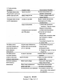
DIGITAL EARTH RESISTANCE TESTER
"r
i'I
..v
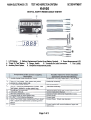
1. LCD Display. 2. Battery Replacement Symbol (Low Battery Symbol).
3. Green Measurement LED.
4. "Press To Test- Button.
5. Range Switch.
6. Terminals for Lead Connection.
7. Test Leads.
8. Auxiliary Earth Spikes.
9. Simplified measurement probe.
detailed on oaoe2. Operationalinteoritv.
Electrical continuity
limits
baa~
plastic
clear
a
in
Set of 3 Test Leads. Red, green and yellow,
~cked
2
---
3. I 2 ~~uXIlialV Earth Spikes.
I
Visual
-
insoection.
6. I InstructionManual:
I Correct InstructionManual.
7.-' WarrantyReaistratiQnCard.
I Standard Robin Warranty Reaistration Card.
8. CarryingStrap in cI~arsfapled baa.
I Correct strap.
9. I 6 _x R6 1.5 Volt Alkaline Batteries
'Correct tvoe.
10 Grey ,PVC Carry Case containing a Foam Insert
ColTed Case. Checkzips function
-,
with 2 Zipped Compartments containing all the
above.
11.
Carton
Correct cartonwith currentaddress,logosand
references.
Page 1 of 2
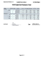
ROBIN ELECTRONICS LTC
CALIBRATION
ac DEPARTMENT
ACCURACY
K4iO5 Digital Earth Resistance Tester
Authorised
Date
Page 2 of 2
01"1 DC i'lOCO
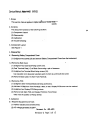
Service Manual: ~.~eeel4 ~85
1. Scope
K410S
.
This service manual ap~lies to digital ea~tester :.1oeel~18S.
K410S
2. Contents
This document consists of the following sections.
~
(1) Component Layout
(2) Disassembly
(3) Calibration
(4) Trouble-shooting
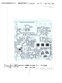
3. Component Layout
See Figure1
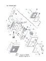
4. Disassembly
4.1 Removing Battery CompartmentCover
(1) Untighten two screws (20) and remove Battery Compartment Cover from the instrument
4.2 Removing Back Case
,.
(1) Untighten four back-case-fixing screws (15).
(2) Peel Terminal Plate (17) off Back Case using a pair of tweezers.
(3) Untighten five Terminal-Block-fIXing screws (16).
Use causiton not to lose plain washers each of which is put throuth the screw.
(4) Remove Back Case (14) from Front Panel (5).
4.3 Removing PCB
(1) Untighten three Terminal-Block{12)-fixing screws{13).
(2) Lift Main PCB{9) from Front Panel{5) a little, so that Display-PCB-screw can be reached.
(3) Untighten four Display-PCB-fixing screws.
(4) Remove both Main PCB and Display PCB from Front Panel.
Take note the positionof Range Switch.
5. Calibration
5.1 RequiredEquipmentandTools
(1) Varibleresistancebox(0-200ohms)
(2) AC voltagegenerator(O-200V)
Document No. 490-4001
Revision O. Page 1 of
b
(3) Frequency counter (can measure about 820Hz)
(4) DC voltage generator (6-9V, output current more than SOmA)
(5) Digital multimeter (for current consumption monitoring; unnecessary if the DC voltage
generator has a current monitor on it)
(6) Calibration screw driver
(7) Two 500 ohm resisters (for testing effect of earth resistance of auxiliary earth bars)
(8) Test lead (Use the green wire of the M-7095 lead set. or a lead less than 1 meter long and
more than 3.3mm in outside diameter to reduce the effect of test lead resistance.)
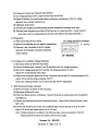
5.2 Preparation
(1) Peel Name Plate off Front Panel.
(2) Remove the batteriesfrom the battery Compartment
(3) Connect + and- terminals of the DC voltage
DC voltage generatorconnection
to - terminal
generator to the battery connectorsobserving
correct polarity.
to + terminal
5.3 V Range and Low Battery Voltage Calibration
(1) Set Range Switch to "EARTH VOLTAGE."
(2) Using connection leads. connect P and E temlinals to the AC voltage generator.
,
(3) Set the DC voltage generator to 9V and the AC voltage generator to 190V.
Adjust VR1 so that display reads 190.0.
(4) Remove the connection leads from P and E temlinals and set the DC voltage generator to 6V.
Adjust VR3 so that the display indicates "BATT."
Set the DC voltage generator to 6.3V and check that "BA Tr' disappears.
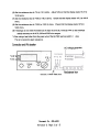
5.4 EarthResistanceRangeCalibration
(1) Makeconnections
as shownon the nextpage.
(2) Set RangeSwitchto 20 ohms.
(3) Press Test Buttonand tum it dockwise. Check if the button is locked down and the operation
LEDlightsup.
(4) Replacethe resistnaceboxwiththe frequencycounter.AdjustVR2 so that the counterreads
820+/-5Hz.
.
(5) Connectthe resistanceboxto the unitto calibrateagainand set the box to .0 (OF0.1)ohm.
Adjust VR5 so that the display reads 0.00 to 0.02 ohm.
Note: If dispay readings are unstable in the following steps, reverse connection of the DC
voltage generator's plug to the socket outlet of mains supply.
Document No. 490-4001
Revision O. Page 2 of b
(6) Set the
resistancebox to 819 (or 19.1) ohms. Adjust VR4 so that the display reads 18.72 to
19.28 ohms.
(7) Set the resistance box to 8190 (or 190.1) ohms.
ohms.
Check that the display reads 187.2 to 192.8
..
(8) Set the resistance box to 81900 (or 1900.1) ohms.
Check that the display reads 1872 to
1928 ohms.
(9) If readings do not meet the tolerances in steps (7) and (8), re-adujst VR4 so that readings
satisfy accuracy on all of 20, 200 and 2000 ohm ranges.
...
8
When using a lead other than the green wire of the M-7095 lead set, add'0.1
ohm.
This is to cancel the lead resistance.
Connection and VRs location
AC voltagegenerator
v" R 5
VR4
I
Ic
0
VRI
'R 3
0
VR2
0
0
0
f
Resister, 1/4WF 499 ohms
Document No. 490-4001
Revision O. Page 3 of -6
Resistancebox
5. Trouble-shooting
Svmotoms
PossibleCauses
The display blanks when
Fault in the circuit
RangeSwitchis .setto any.
position other than OFF.
Recommended Remedies
If current consumption is not
30-50mA.reolacePCB
'. Batteryvoltage is low.
If battery voltage is below 5V,
reolace batteries.
The display does not read
A break in a test lead
in ACV measurement
Repair or replace the test lead.
If test leads are OK, f6110w
remedie"s below.
FaultyTerminalBlock.
..
.
A terminal has poor connection
with PCB pattern.
1) Checkeachterminalfor
continuity.If thereis a break,
ReplaceTerminalBlock.
2) Check continuity between
each terminal and relevant
PCB pattern.
If there"is poor connection, clean
the PCB pattern or tighten
the terminal.
If no problem is found in 1) or
2). reolace eCB.
The display shows
Exessiveearth resistnace at
1) Give water to the ground
overrange indication and
auxiliaryearth bars (connected
around the bars.
three decimal points in
to P or C terminal).
2) Relocate the bars.
earth resistance
3) Change the depth of the tip
measurement
The display shows
of each bar.
A break in a test lead
overrangeindication,
unable to make earth
continuitv.
Fault in the circuit
resistancemeasurement
Inaccuratereadings in
If there is no break in the lead,
Reclace PCB.
Effect of earth voltage
earth resistance
measurement
Check the lead to E terminal for
Check earth voltge before
makino measurement.
Effectof earth resistnace at
auxiliaryearth bars
Check if three decimal points
are shoYmon the disclav. "
The instrumentis out of calibration If no problem is found in the
above checks, follow section 5
for calibration.
Document No. 490-4001
Revision O. Page 4 of b
','~
95.08.07
~
I.~a
I~
I ."
00-19060
IJ;ji>PCB 50-13808
'
I
., .
I~",
07-1202C
I cs+
~
~
(00 1906D)
~~.tor-
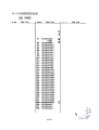
Part Type
Desi.nator --
Part T voe
D.8i~8tor
Part TyPe
D
A
R1
R2
R3
R4
R5
R6
R7
R8
R9
R10
R11
R12
R13
R14
R15
R16
R17
R18
R19
R20
R21
R22
R23
R24
R25
R26
R27
R28
R29
R30
R31
R32
Raa
R36
R37
R38
RK73H2A2kF
2;2k
RK73H2A3kF
RK73K2A47kJ
RK73K2A47kJ
RK73H2A10kF
RK73K2A10kJ
RK73K2A10kJ
RK73K2A10kJ
RK73K2A10kJ
RK73K2A10kJ
RK73H2A150F
RK73H2A10kF
RK73H2A10kF
RK73H2A10kF
RK73H2A10kF
RK73K2H3.9kJ
RK73K2A4.7kJ
RK73K2A100kJ
RK73K2A100kJ
RK73K2A100kJ
RK73K2A100kJ
RK73K2A100kJ
RK73K2A100kJ
RK73K2A100kJ
RK73K2A100kJ
RK73K2A100kJ
RK73K2A100kJ
RK73H2A100kF
RK73H2A100kF
RK73H2A100kF
RK73H2A100kF
RK73H2A200kF
RIE~aI12.~.
~5e~
RK73K2A3kJ
RK73K2A3kJ
RK73K2A3kJ
.8
8
c
1'",
x '-"'-
-~
(OO-1906D)
De8ianator
Part Tvpe
c..im8tor
Part Type
BT1 5UM3x 6
EMF1 NFM40RO10101
~~~~-=~~~R1 ~G22a
U1
U2
U3
U4
U5
U6
U7
U8
U9
U10
U11
U12
U13
Uf4
U15
U16
U17
U18
U19
U20
U21
U22
NJM555M
uPD4053BG
uPD4013BG
NJM2904M
NJM2904M
NJM2904M
NJM2904M
NJMOP-o7M
NJMOP-o7M
uPD4053BG
NJM78LO5UA
NJM7660M
TC7116CKW
uPD4066BG
TC4071BF
uPD4030BG
uPD4030BG
TC4069UBF
KLC-732P
uPD4001BG
TC4017BF
05BCOA
EMF2
JP1
L1
LP1
PTO1
51
52
T1
VR1
VR2
NFM40RO10101
HEADER 14
65-1091A
TLG124A
911P97E102YV10
41055W
5PPH13-LB
65-1177
TMO3KJB500
TMO3KJB1k
sooe
VR3
VR4
VR5
VRD1
Desimator
Part
Type
c
c
c
B
B
TM03KJB500
TMO3KJB2k
TMO3KJB10k
Z1047
~ ;g.-.[J
'~li4~
"'-'~":#
-2
0
~
Fig. 1 Component Layout
/"
-
"
':~
'"
"~
, .
"'""
..
...
\
E{"
!
\
""
G)
'-
""
-
\
-
$Co.+--
~L
'"
/I~
(
~
~-.:-,
l".A
~
II' ~~
G\DJ
~,
".
.~ ~~--J-.~
'"
'",
"
/
/
r;')
.,
@
-~c~~f~
c
,::Jf,
"
~
~.
~~
\
\
lD
e
Document ~o.
Revision O.
490-4001
PageS'of ~
OJ
0
.c
0
-
~
.c
E
0
.-
in
0
-
U)
~
OJ~
01
~
u
.x.
.c
c
.c
CO
U)
U)
OJ
~
...:
~
-J ~
~
0
6
~
co'
C
U')M
, 0
OLn
O~
OM
E
~
cU
0
X
:s
CD.
..-
c
Q)
.c
='
..-
~
"Uj:
.c
..~
->E
.c
OJ
U)
U)
CO
OJ
c
_0.-c"
...
00)
:
N
0
I
:6
.
I
'-
0
~ 0)
0'
,...
in~
e
CO.
Q
-
-
CO
Z
0
O\'~
00\
00
'Ln"'"
0 0
'.
0
'y¥)0
"\1'~cop..,.O),-
,...
0
0
0
::
. ~6
G) ;
cccOJc ero
..g~
U)
Q
OJ (,J~,
U).x.~
0
u -0
'c c01
Ln' -Co
z
1/'1
-0
~
~,
SO
16-1
U)
.-J
U)
~
CO
a..
OJ ''OJ
CO
0...0-E ~
(/)
. ~
r-.. Z
Q)
"0
0)
"5
-u
.9
y-
o
I
-~
aJ
,
,.
Q.
U
co
CI)
Q)
CI)
~
.D
~
~
~
.'?;:- x
.
Q).c~
3:
cn.
:5
.-.c
..(J
cu
..c
0
(J
~
Q)
~
cu
.Q
.c
~
X
>-. 0
3:~
Q)Z +
U)
3:EM
X
U)
CO Q)
-
-
0
--N
0)
..~
m
..-
>-
:c
E
Q)
cn
cn
CI] co
So,4
'0
Q)
r-4
8
>
0
u
C
Q)
E
a.
0
roo
roo
roo
0
0
0
CO
Q)~ CO a.
M
-a.E-=
Q)
N
~
0
Q)'-'-Ocn
Q)
~
'"
C
.
M
.
I
~
M
0
It1
0
0
0I
.
,
I
o~
C)C
.-
Q),-'-
U
~:g:
Q)~
'-
U
cn
Q)
C
0
U
U"J:
aJ
C)C
.-
>UOZU)UOU'S
cnU+COcnU
J:
Q)
3:
C
0
(")
"\1'.0
1(")
~,MO,
00
LnO
0
M
.
0
CO.c
aJ cn
u.
..-
N
0(")
.0
..N
0
0
0
N(")~~""'o)"-
~
,
0
0
0
-,-,
1(")
~,MO
00
LnO
0
I
M
0
°
U
0
~
M
0
co
0
0
CO..
aJ aJ
'-
Q)Z~CO
~"+
u
CO 3:..QM
.N
E
E .oM
:c
>-
-a) "00
::5 E
~ -::5
...
o~
..-,
'i).ot
r M
00
OLn
00
~
1"'\
MW
-:=0
0
,,-
-
t
~
I
0)
0
,
~
~
~
0\
0
r--
co
cn
"0
Q)
:1:
c
Q)
E
~
::)
CO
cn
Q)
Q)
C)
cn
~
C
.-
"0
Q)
EI
."
cn
"0
..9!.
If)
c
.-c.
E
'CO
~m
02:"
~Q)
~~
2:"
'~
(J
cn
~
0
CO.-
.c
1::
~
m
m
mO)
t"'~
00
0,
0
0
Q)
~
0
~
0
0
~
~
0
r-..
~
~.
0
In
0\
0
r-..
It'