1
Repairs of the electrical installation in
Škoda vehicles
Self-study programme
ŠKODA Service®
91
Introduction
This publication was created with the aim of supporting the service network of Škoda in the proper execution of
repairs of the electrical installation for vehicles and summarises all the important principles and recommendations regarding the prescribed operation, use of recommended tools and equipment according to the valid service
documentation, including the notes for the corresponding passages in the current literature.
At the same time, the examples referring to incorrect repair procedures which are listed most often and occur
most frequently as well as their negative effects and recommendations on how the repair should be performed in
the correct way, are listed here.
The corresponding module of the service training is an addition to this Self-Study Programme No. 92.
2
GB
Contents
Introduction ...................................... .......................................................................................................................................... 2
Contents
................................................................................................................................................................................... 3
1. Škoda service documentation: Correct method of carrying out repairs of the electrical installation ............................ 5
2. Use of recommended tools and devices ..............................................................................................................................15
3. List of valid TPI, referring to the repairs of the electrical installation in Škoda vehicles .....................................28
4. Common errors when carrying out repairs of the electrical installation...................................................................29
5. Repairs of the plug connectors and terminal strips ........................................................................................................37
GB
3
4
GB
1. Škoda service documentation: Correct method of carrying out
repairs of the electrical installation
Source: Škoda workshop manual; electrical systems - general information; 97 - cable - selected chapters relating
to the repairs of the electrical installation.
1.1. Compliance with the repair procedures according to the valid service documentation
General repair instructions for the electrical system of the vehicle
WARNING!
› On modules affixed with stickers that warn of high voltage in the system of the vehicle, the residual voltage
must be eliminated before the repair (e.g. switch on the consumer after disconnecting the battery and
subsequently switch it off again).
› Some tools have a protective cap which has to be refitted on the tip of the tool after using it, because of the
possible injury and damage to the tip.
Note
› Comply with country-specific regulations.
› When disconnecting and connecting the battery, follow the prescribed procedure ⇒Electrical systems;
repair group 27.
› Before beginning the repair, the cause of damage must first be resolved, such as sharp edges of the body parts,
defective power consumers, corrosion, etc.
Note
› If possible, do not loosen the earth straps at the body (risk of corrosion).
› Comply with the current instructions in the relevant workshop manual when carrying out repairs.
General repair instructions for conductor bundles and plug connectors
Note
› Comply with the general repair instructions for the electrical system of the vehicle
› Do not solder when repairing the electrical system of the vehicle.
› After pressing, the press coupling must shrink when using a hot air gun in order to prevent moisture
from penetrating.
› The shielded cables, such as, for example, the cables for the speed and knock sensors, must not be
repaired. If damaged, they must be completely replaced.
› If the required cross-section of the conductor bundle does not exist in the repair set, the next larger
cross-section must be used.
› Mark the repair points with a yellow adhesive tape.
› The points of the cable set, which are marked with the yellow adhesive tape, identify the previous
repair.
› Carry out a function test after each repair. If possible display the faults stored in the memory,
erase the faults and if necessary carry out the basic setting of the repaired system using the
VAS diagnostics, measuring and information system
GB
5
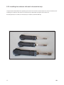
1.2. Repair of the conductor bundles and plug connectors
Required special tools, test and measuring devices and auxiliary means
› Service case for the repair of the electrical bundles S504500V
› Set with release tool (cutter) for plug connectors S506815V
› Set with release tool (cutter) for plug connectors S506825V
or:
› Service case for repair of electrical bundles VAS 1978B
› Set of release tools (cutter) for plug connectors VAS 1978/35 supplemented by the set of release tools (cutter)
S506840V
The service case contains the necessary tool (except the set of release tools) and the material.
Quality repairs of the electrical networks can be carried out with the service case. The repairs of the plug
connectors and interrupted lines can be carried out with the tools.
The complete repair instructions are used for the repair of crimped plug connectors and press couplings, that are
connected to the conductor bundles in the vehicle.
Repair instructions from the ⇒ Electronic catalogue of original parts (ETKA).
The crimping tool provided with three different pressing profiles and the hot air gun serve to shrink the press
couplings in order to properly connect the cables.
For any subsequent order, simply name the order number for the spare part which you can find in the converter
table enclosed with the operating instruction.
The set of release tools (cutter) is used to release various primary and secondary plug connectors in the terminal
trips.
The systems with circular plug connectors and the flat contacts with one or two detents can be properly released
or installed as well as the simple cables can be sealed using the cutters.
Note
› Additional information and use of the set ⇒ Operating instruction for the service case.
› The assignment of the correct release tools can be found in the table, see ⇒ Operating instruction
for the set release tools.
6
GB
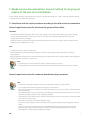
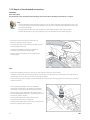
1.2.1. Repair of the cables for pyrotechnic components
Note
› Comply with the general repair instructions for the electrical system of the vehicle.
› Comply with the general repair instructions for the conductor bundles and plug connectors.
WARNING!
Inadequate repairs of the cables for pyrotechnic components, e.g. airbag, belt tensioner, may result in
insufficient protection of the passengers.
› To ensure a quality repair, the repairs of the cables for pyrotechnic components must be carried out exclusively
with the service case for the repairs of electrical bundles using original spare parts (connector sockets,
contacts, conductors, see ⇒ Catalogue of original parts)
› The cables on individual airbag units must not be repaired.
› The corresponding airbag modules must be replaced for safety reasons in case of damage to the cables or the
plug connectors on the airbag modules.
Note
› Repairs on the cables for pyrotechnic
components can only be carried out on
two repair points of the cables.
The repair points increase the electrical
line resistance and thus induce faults in
its own diagnostic system.
› The cable with the repair point must not
be put back into the original bundle in
the vehicle and must be visibly marked
with the yellow insulating tape.
Note
› The repairs in the area of the
pyrotechnic components should be
carried out at a distance of at least
30 cm to the next connector socket.
This together with the marking of the
repair point with the yellow adhesive
tape enables a quick overview of
previous repairs.
› Both cables for the airbag igniters are
twisted with a twist length of
20±5 mm. This twist length must be
kept for the repair of the twisted cable.
GB
7
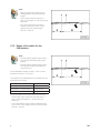
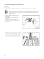
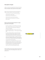
Note
› After the repair, both cables for the
airbag igniters must have the same
length.
Upon rotation of the conductors -1and -2- the length -A- = 20 mm must be
observed.
› Thus, the conductive part without
rotated conductors (-arrow- in the
repair point) must not be longer
than -B- = 100 mm.
1.2.2. Repair of the cables for the
CAN databus
Note
› Comply with the general repair instructions for the electrical system of the
vehicle
› Comply with the general repair instructions for the conductor bundles and
plug connectors
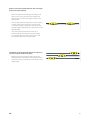
The unshielded twisted pair cable -1- and -2- with a
diametre of 0.35 mm 2 or 0.5 mm2.
The cables for the CAN databus are provided with the
following colour coding:
CAN High line, drive
orange/black
CAN High line, Convenience
orange/green
CAN High line, infotainment
orange/purple
CAN Low line, all
orange/brown
› After the repair, the two bus lines must have the
same length. Upon rotation of the conductors -1and -2- the twist length -A- = 20 mm must be
observed.
› Thus, the conductive part without rotated conductors (-arrow- in the repair point) must not be longer
than -B- = 50 mm.
8
GB
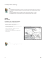
1.3. Using the set for cleaning the contact areas VAS 6410
The repairs in the area of the contact transfers for threaded connections of cable sets in the high power circuit
and battery connection must be carried out with a set for cleaning the contact areas VAS 6410 (releasing and
charging current, grounding conductors, battery terminals and poles).
Note
› The repairs shown in the illustrations serve only as an example of how to use the set.
› Set for cleaning the contact areas VAS 6410
GB
9
1.3.1. Repair of the cable lugs
Note
› To avoid breaking the threaded connection such as when exceeding the tightening torque, due to
the lack of static friction in the thread, no rust remover, contact spray or grease must be used on
cable lugs.
› The grey abrasive discs are only suitable for minor contaminations and "soft surfaces".
› The red abrasive discs are only suitable for minor contaminations and "hard surfaces".
WARNING!
Risk of accident!
Pay attention to the warning notes and safety
instructions when working with batteries.
– Disconnect the earth cable of the battery ⇒
Electrical systems; repair group 27.
– Unscrew the capnut and remove the cable lug from
the threaded connection.
– Check the cable lug in regards to corrosion,
contamination, damage, etc.
– Select a respective adapter and an appropriate
polishing pad.
Note
› Alternatively, a grinding slip can be used.
10
GB
Note
› Clean the cable lug carefully, so that the zinc coating is not removed.
› In regards to the different thicknesses of the zinc coating, it is necessary to perform a visual inspection on the
cleaned surface in the course of the cleaning process.
› Before beginning the repair, the cause of damage must first be resolved, such as sharp edges of the body parts,
defective power consumers, corrosion, etc.
– Fit an appropriate adapter onto the cable lug and
remove rust and dirt by rotational movements.
Check the cleaned area continuously.
– Check the cable lug for burrs, if necessary remove
them with a burr removal tool.
– Reset the cable lug and tighten to the specified
tightening torque.
Note
› The required tightening torque must
be kept for an optimum contact of the
cleaned components.
– After tightening, preserve the connection with a
suitable preservative.
– Comply with the procedure for battery connection ⇒
Electrical systems; repair group 27.
GB
11
1.3.2. Repair of the threaded connections
WARNING!
Risk of accident!
Pay attention to the warning notes and safety instructions when working with batteries ⇒ Page 2.
Note
› To avoid breaking the threaded connection such as when exceeding the tightening torque , due
to the lack of static friction in the thread, no rust remover, contact spray or grease must be used
for battery terminals.
› The grey abrasive discs are only suitable for minor contaminations and "soft surfaces".
› The red abrasive discs are only suitable for minor contaminations and "hard surfaces".
– Disconnect the earth cable of the battery ⇒
Electrical systems; repair group 27.
– Unscrew the capnut and remove the cable lug from
the threaded connection.
– Check the threaded connection in regards to
corrosion, contamination and damage.
– Select a respective adapter and an appropriate
polishing pad.
Note
› Clean the threaded connection carefully, so that the zinc coating is not removed.
› In regards to the different thicknesses of the zinc coating, it is necessary to perform the visual inspection on
the cleaned surface in the course of the cleaning procedure.
› If the underlying layer of copper is exposed when removing the zinc coating, a galvanic cell can occur, causing
intense corrosion.
– Fit an appropriate adapter onto the threaded
connection and remove rust and dirt by rotational
movements. Check the cleaned area continuously.
– After cleaning, screw together the connections to
the specified tightening torque, if necessary with the
protection against rotation.
– Preserve the threaded connections with the
appropriate preservative ⇒ page 29.
– Comply with the procedure for battery connection ⇒
Electrical systems; repair group 27.
12
GB
1.3.3. Cleaning the battery terminals and poles
WARNING!
Risk of accident!
Pay attention to the warning notes and safety instructions when working with batteries ⇒ Page 2.
Note
› To avoid breaking the threaded connection such as when exceeding the tightening torque , due to
the lack of static friction in the thread, no rust remover, contact spray or grease must be used for
battery terminals.
– Disconnect the battery ⇒ Electrical systems;
repair group 27.
– Check the battery terminals for corrosion or
contamination.
– The battery terminals are cleaned by circular
movements of the wire brush for battery poles
and terminals.
– The battery poles are cleaned by circular movements
of the cleaner for battery terminals and poles, which
is placed with the underside on the battery pole.
– After cleaning, comply with the procedure for battery
connection ⇒ Electrical systems; repair group 27.
GB
13
1.3.4. Treatment with preservatives
Note
› The lack of preservatives can cause damage and failure of the on-board power supply.
› Risk of corrosion.
Note
› All threaded connections must be tightened to the specified tightening torque.
› Use a container with an attached hose for applying the preservative.
› Conservation wax is used for cool areas.
› Conservation wax for cavities is used for warm areas.
› The preservative automatically penetrates at the appropriate points through the capillary action.
– Keep the hose under the conductor shoe and spray
around the pin and cable lug.
– Keep the hose above the conductor shoe and spray
around the pin and cable lug
14
GB
2. Use of recommended tools and devices
2.1.1. Service case VW (VAS 1978B)
The repairs of individual components of the electrical installation (conductors, plug connectors, terminal strips,
etc.) of the Škoda vehicles as of model year 1996 must only be carried out using the recommended set of tools and
components that are part of the service case.
Currently, it is recommended to use the VW-service case (VAS 1978B) that is also used by other corporate brands
for this purpose.
Legend
Note
These symbols with explanations are given in the operating instruction of the service case and
describe the various operations for the repair of the electrical installation of the vehicle.
Unlocking devices
Unlocking of secondary fuses
Unlocking of flat rack systems
Unlocking of circular rack systems
Assembly devices
Devices
Use of devices
Stripper
Insulation with insulated pliers
Crimping tool with adapter
Cutting with insulated pliers
Electrical hot-air fan
Swaged socket fi ttings with crimping tool
Hot-air gas fan
Shrinking with electrical hot-air fan
Folding knife with a blade
Shrinking with hot-air gas fan
Plug connector for adapter, worldwide
Cable shortening with folding knife with a
blade
Other pictograms
Repair of individual conductors
For more information - see "Technical
information"
Please observe the following instructions!
Warning!
GB
Cutting off
Directional arrow
Warming up
Additional information
15
The service case VAS 1978B contains the following tools*:
Stripper with conductor cutter (stripping and cutting off the conductor)
Stripper with conductor cutter for stripping and cutting
off the conductors.
A stripper of 6-7 mm is used for stipping the conductor
ends.
* The description and the symbols are taken from the operating instruction enclosed in the service case.
16
GB
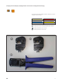
Crimping tool with adapter (crimping head for various sizes of swaged socket fittings)
The service set VAS 1978B includes 4 different sizes of
swaged socket fittings.
yellow
for 0.35 mm
12
2
blue
for 1.5–2.5 mm2
red
for 0.5–1.0 mm
11
11
2
yellow
11
for 4.0–6.0 mm2
11
Crimping tool with crimping head for JPT contact
12
13
Crimping head for 0.35–2.5 mm2
Crimping head for 4.0–6.0 mm2
GB
17
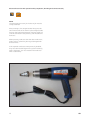
Electrical hot-air fan with special nozzle (completion, shrinking and connection seal)
NOTE:
The operating instruction for the hot-air fan must be
strictly observed!
After pressing in, the swaged socket fitting must be
shrunk with a hot-air fan. Warm up the swaged socket
fi tting in the longitudinal direction from the inside out
until the connection seals perfectly and the adhesive
flows out.
When pressing, make sure that the other conductors,
plastic parts or upholstery do not get damaged with
the hot nozzle.
If the repaired conductors were previously bundled,
they must be insulated again with a yellow insulating
tape. If necessary, you must reattach the conductor
with a cable clamp.
18
GB
Hot-air gas fan with special nozzle (completion, shrinking and connection seal)
NOTE:
The operating instruction for the hot-air gas fan must
be strictly observed!
The hot-air gas fan is delivered as part of the equipment upon request. The butane gas (igniter gas) is
used, so that gas bottles for refilling can be bought
commercially.
The advantage is that it does not have to be fed in.
GB
19
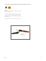
Folding knife with a blade
Mechanism for quick and easy replacement of the
blades
2
1 Pad under the thumb for maximum pressure
13 Fixture of the blade with locking device
14 Release lever for quickly snap shutting the blade
11
20
GB
In addition to the service case, a set of release tools (cutter) is required for repairing the electrical installation,
for releasing the plug connectors from the terminal trips and for their reinstallation, in particular:
- universal device for releasing secondary fuses at terminal strips,
- unlocking devices for flat and circular connectors,
- assembly devices for fi tting the seals in the terminal strips.
The use of this set and the correct procedure for unlocking and releasing the plug connectors,
including their reinstallation, are described and illustrated in detail in chapter 5 of this SSP and
in the relevant operating instructions, which are enclosed with each set of release tools.
Use of service case for the repairs of the electrical installation
The following points are emphasised and extracted from the detailed description of individual operations,
see instruction VAS 1978B - technical information (enclosed with each case):
Safety instructions
For all repairs, please keep the current information enclosed in the relevant technical manuals and
in the manual "Service Technics".
Important:
Before working on the electrical system, the flat band of the battery must be disconnected.
Before carrying out the repair procedure, you must first of all eliminate the cause of the fault
(e.g. sharp edges of the body part, defective consumer, corrosion, etc.). For more information,
such as the instructions for the installation and removal of individual assembly parts, can be
found in the corresponding service manual.
Only yellow conductors must be used for the repair of cable sets. These yellow conductors and all
the points at the cable set, that are marked with the yellow insulating tape, identify the previous
repair.
A function test must be carried out after each repair. If necessary, you must read off the data in the
fault memory and restore the original state of the system.
GB
21
Assignment of individual conductors, conductor seals, swaged socket fittings,
press gutters
Conductor and conductor seal
The service set VAS 1978B does not include all the cable cross-sections used in the vehicle. If the cable crosssection is not available, you must use the next higher cross-section.
Bags which include the service conductors are colour marked. The conductor seals are in compartments that also
differ in colour. According to the colour marking, you can select the corresponding press coupling, conductor seal
and gutter for the crimping tool.
Example
If you want to use a conductor of 0.5 mm with the red identification from the bag, you must use the colour
identification for the following red press coupling. The red press coupling must further be pressed into the gutter
of the crimping tool marked in red. The corresponding conductor seal also lies in the compartment with the red
identification.
Separate conductor
Cable cross-section
in mm2
Press coupling
Colour
identification of the
compartments for
the conductor seal
Press gutter/
crimping tool
0000 972 002
0,5
red
red
red
Swaged socket fittings, press gutters for crimping tool
The service set VAS 1978B includes four different sizes of swaged socket fi ttings.
yellow
red
blue
yellow
for 0.35 mm
for 0.5–1.0 mm
for 1.5–2.5 mm
for 4.0-6.0 mm
Contacts, gold contacts
The conductor contacts are available in the standard or gold-plated version.
When carrying out the repair, the contact to be used must always be the same version as the series contact.
The gold contacts are used for example on lambda probes or on knock sensors.
22
GB
Heat-resistant cables
At various points in the vehicle - especially in the engine compartment - heat-resistant cables are used.
The heat-resistant cables can be recognised on the duller and softer insulation.
To carry out repairs on these conductors, only the heat-resistant cables must be used.
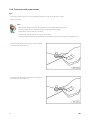
Conductor seal
The conductor seal protects against dust and ingress
of water into the contacts of the fuse body. They are
used for example in the engine compartment and are
always installed after the repair.
The conductor seal is crimped together with the contact at the conductor in series. This is different when
carrying out repairs. Before pressing in the service
conductor, you must first fi t a seal onto the conductor.
While doing so, the stop sleeve at the crimping point
must face away from the fuse body (see drawing).
The conductor seal must always correspond to the
cross-section of the relevant service conductor.
The outer diametre refers to the diametre of the fuse
body chamber with contacts.
For the assembly, only use the appropriate assembly
devices.
GB
23
Description of repair
Make sure that the swaged socket fittings are shifted
below one another when repairing certain conductors
within a bundle (so that they do not lie side by side).
When interrupting the electrical line, the following
steps must be carried out in the following order:
-
Cover both parts of the interrupted conductor
and loosen from the bundle
-
Strip both parts of the broken line
-
Connect the line with a press coupling
-
Seal the connection (resistance to moisture
penetration).
Repair of the uninterrupted conductor at a repair
point (with an interruption)
-
Cover the conductor to be repaired on each side
over a length of approx. 20 cm, starting from the
point of interruption and release. If necessary,
remove the bandage.
-
Insulate the ends of both conductor parts over a
length of approximately 6 - 7 mm using an insulated
plier.
-
Fit the insulated conductor ends into the press
coupling of the appropriate size/colour on both
sides and press the coupling together with the
corresponding press jaw (see colour identification)
on both ends using the pliers. Thereby the insulation of the conductor ends must not grip into the
conductive coupling part (and must not be pressed).
To the contrary, the insulated conductor ends must
not protrude from the coupling.
-
Subsequently, the swaged socket fitting must be
heated along the centre of the coupling towards
the outside with a hot-air fan until it fully seals and
the sealant flows out. The heating temperature
is set according to the requirements of the
manufacturer (usually 350 degrees Celsius).
Warning: When fitting the seal, make sure that the hot
end of the fan does not damage another cable or the
plastic parts.
24
GB
Repair of the interrupted conductor with two repair
points (two interruptions)
-
Cover and release the interrupted conductor for
repair in the vicinity of both interrupted points
(see the repair of the interrupted conductor at a
repair point)
-
For the repair between the points of interruption,
use the yellow repair conductor from the case
or from the supply of spare parts with the same
(initially higher if possible) cross-section as for the
repaired cable.
-
The repair procedure (selection and use of
press couplings, their pressing on and sealing)
is consistent with the repair procedure for the
interrupted conductor at a repair point.
Installation of swaged socket fittings for repairs of
certain conductors within a bundle
-
GB
Make sure that the swaged socket fittings are
shifted below one another when repairing certain
conductors within a bundle (so that they do not lie
side by side).
25
Safety instructions
When repairing the conductors in the area of the airbag and the seat belt tensioners as well as in
damp places, certain rules must be observed.
It is possible to repair a maximum of 2 points on each adapter!
The repair points increase the electrical resistance of the conductor and can cause faults in its own
diagnostic system.
Roll up the original cable set including the repair points. Mark the repair point with a yellow
insulating tape.
When repairing the airbag conductors and the seat belt tensioners as well as in damp places,
you must always crimp the swaged socket fittings. This will prevent corrosion.
Repair points in the area of the airbag or
the seat belt tensioner
max. 30 cm
Points in the area of the airbag or the seat belt
tensioners that are being repaired must be located
a maximum of 30 cm from the next fuse body with
contacts (terminal strips). This, together with the
identification using a yellow insulating tape, allows a
quick overview of the previously performed repairs.
Repairs of the terminal strips
(plastic fuse body with contacts)
For technical reasons the fuse body with contacts
for the cutting and clamping procedure must only be
delivered with cutting and clamping plug contacts.
If you do not need these contacts, you can dispose of
them in the same manner as any other fuse body with
contacts.
Service conductors are already available with
appropriate crimp contacts.
See order information and catalogue of spare parts
(EP 198 "Electrical connecting elements").
Cutting and clamping elements
26
GB
Unlocking and removing the terminal strips (fuse bodies with contacts)
The shapes of fuse bodies with contacts in the operating instruction are only informative and clearly describe the
work with the secondary fuse.
General notes
To unlock, always use specific unlocking devices. Contacts must never be released from the fuse body by force.
Details can be found in chapter 5.
The damaged fuse bodies with contacts must always be replaced.
A new fuse body with contacts can be ordered via the OTC division Kassel.
The attachments of the chambers and pins can be found partly at the secondary fuse or on the rear of the fuse
body with contacts.
The secondary fuse differs from the rest of the fuse body with contacts in its colour. Thus, the identification of
the secondary fuse and the work procedure is made easier.
The installation points for the plug connections can be found in the chapters "Circuit diagrams", "Fault Finding
- Electrical" or "Installation points".
The detailed description for unlocking the fuse body with contacts can be found in the description of the set for
unlocking devices, VAS 1978/35.
To meet the standard of Škoda, another set of tools must be purchased in addition to the set of release tools
(cutter) S506840V.
For unlocking individual contact systems, comply with the operating instructions in the manual.
2.1.2. Škoda service case
For repairs of electrical installations in Škoda vehicles as of model year 1996, a set of tools must be used which is
also included in the service case of Škoda (the order no. was S 504500V, currently this case is no longer available
and it has been fully replaced with the VW service case (VAS 1978B) from which it originated). The tools, devices,
components and repair procedure are identical for both cases (for details, see the relevant instructions enclosed
with the sets).
The Škoda service case does not include a set of release tools ("cutter") to release the contacts of the terminal
strips. For the repairs of the terminal strips with plug connectors, this service case is supplemented either.
A) with the set of release tools S 506815V and S 506825V
or
B) with the set of release tools VAS 1978/35, supplemented with the set S 506840V.
The use of all the sets is explained in the relevant operating instructions enclosed with the sets.
GB
27
3. List of valid TPI referring to the repairs of the electrical
installation in Škoda vehicles
- 2014734 faults in the Parking Assist System (Octavia II)
- 2018564 (fill in the designation)
- 2026007 faults in the engine electronics, caused by the collision of the electric motor bundle (Fabia II)
- 2027432 rain penetrating the terminal strips for fog lights, daily lighting, horn and into the terminal strip which
feeds the independent heating (Superb II).
The details regarding this technical product information as well as the other newly issued TPI,
can be found in ELSAPro or in the portal B2B.
28
GB
4. Common errors when carrying out repairs to the electrical
installation
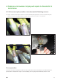
4.1. If the correct repair procedure is not observed, the following can occur
a) Faulty insulation of the cable connection near the lambda probe (possibility of moisture penetrating the
terminal strips of the lambda probe). The repair was not properly carried out TPI 2018564.
Correct procedure
Use a service case to insulate the conductor ends so that the conductor insulation is ensured and moisture
penetration is avoided when using the corresponding press coupling and the following connector seal.
GB
29
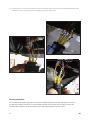
b) The connection of interrupted conductors near the lambda probe is carried out by soldering (breakage of the
soldered connection during operation, inadequate moisture protection).
Correct procedure
Do not solder when repairing the electrical system of Škoda vehicles (see the general repair instructions
for cable sets and plug connectors in the workshop manual). Use a service case in order to connect the
corresponding conductors with the relevant press coupling and seal with the hot-air fan.
30
GB
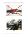
c) When repairing the conductor bundle, re-establish the connection of several interrupted conductors at the
same position in the bundle (problems that arise from the increased diametre of the bundle at the repair point).
Incorrect!
Correct
Correct procedure
Observe the operating instruction enclosed in the service case (see chapter 2 of this SSP, description of repair)
and the connection points of individual conductors shifting against each other).
GB
31
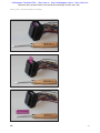
d) The wrong choice of the connection for conductors e.g. repair of the broken/interrupted conductor bundle
for the side or rear door at the point where the bundle bends when opening and closing the door (even after
the repair has been performed correctly, breaking of the repaired conductor will reoccur in close proximity to
the press coupling after a short period of time).
Correct procedure
Carry out the repair (connecting a new conductor with the recommended press coupling including seal) at the
point where breaking of the bundle cannot occur when the door is opened or closed.
32
GB
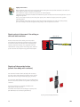
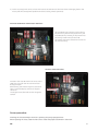
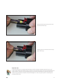
e) Failure to comply with correct values and incorrect attachment of the fuses when exchanging them in the
E-box (and the consequential problems and faults during vehicle operation).
Incorrect attachment of the fuses in the E-box
The fuse SB12 (5 A) is missing in the position
F12 (incorrectly fi tted in the position F11), the
fuse SB19 (30 A) is missing in the position F19
(incorrectly fi tted in the position F18).
The vehicle cannot be started if the fuses are
not fitted correctly.
Incorrect value of the fuse
Instead of the fuse SB13 with the correct value
(30A), the fuse with the value 5A was fitted
during the repair.
While driving, the indicator light for lubrication
lights up and the display "Switch off engine"
comes on.
The engine has stalled and could no longer be
started.
Correct procedure
Checking the fuse assembly in the E-box, replacing the poorly equipped fuses.
When replacing the fuses, observe their correct value and proper attachment in the E-box.
GB
33
4.2.
Problems that may arise when installing non-original equipment and
accessories in Škoda vehicles
4.2.1. Additional installation of electrical equipment - Point of view of the company
Škoda Auto
Škoda Auto recommends that only electrical equipment is installed in Škoda vehicles, that was approved by the
Škoda departments.
The additional installations of non-approved equipment and modifications of the electrical equipment of the
vehicle are not supported by Škoda Auto (see TI-07-001 on portal B2B).
When installing approved equipment, proceed exactly according to the specific installation instruction.
If the installation procedure is not observed (or when additionally installing non-approved equipment), not all of
the electrical functions of the vehicle will operate correctly. There may even be damage to the control units of the
vehicle.
In case of a complaint about a vehicle which was retrofitted with non-approved electrical equipment, this
equipment must be switched off before repairing or transmitting a "technical repair request" (the vehicle
must be restored back to its original condition).
If this is not done and it is determined that the fault was caused by an unauthorised additional installation,
the service is redebited by the warranty department.
34
GB
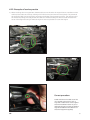
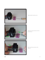
4.2.2. Examples of service practice
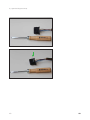
a) When installing the non-original GPS, the GPS cable set was fi tted to the original electric installation of the
vehicle (to the cable set of the QC steering column electronics J527 and instrument panel). This prevented
the original bundle from moving freely, jamming and colliding with the steering column. The malfunction of
the insulation package, the body end of the conductor and the breakage of the fuse SC39 have been the
cause of the engine shutting off while driving and it was not possible to restart the engine.
Correct procedure
Guide and fasten the cable set of the
non-original accessories in such a
way that a malfunction of the original
electrical installation does not occur
(whereby the point of view of Škoda in
regards to additional installations of
electrical equipment applies).
GB
35
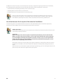
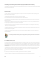
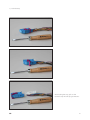
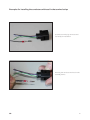
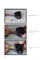
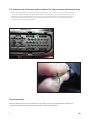
b) When fitting the drawgear in a non-branded service station, a supply conductor of the drawgear was
connected to the supply conductor of the QC steering column electronics. The conductor coupling was
carried out improperly with a quick release coupling (see figure), that has caused the interruption of the
feed for the QC column electronics J527. The vehicle has stopped while driving and the engine could not
be restarted.
Correct procedure
Carry out the installation of the approved type of drawgear for the vehicle in a standard way according to the
installation instruction, which was approved by the vehicle manufacturer (see the point of view of Škoda).
Important note
At the end of this chapter it must be emphasised once more that when relating to the complaint
settlement in regards to the failure of the electrical installation in Škoda vehicles as a cause of
the use of incorrect tools and equipment, non-compliance with prescribed repair procedures,
where appropriate, the installation of non-approved equipment and accessories in the vehicle
is proven, the appropriate complaint to the responsible departments of Škoda is recognised in
any case or covered (the cost of repair and the correction of the consequences of the failure are
covered by the responsable who caused the error by ignoring the rules and recommendations,
no matter whether it is to the service organisation or the owner of the vehicle or not).
36
GB
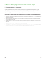
5. Repairs of the plug connectors and terminal strips
5.1. Recommended set of release tools
In order to meet the standards of Škoda, the set of release tools recommended by the manufacturer for the
repair of plug connectors and terminal strips must be used ("cutter"), e.g. VAS 1978/35, supplemented by the
set S 506840V or the set of release tools S 506815V and S 506 825V, which have been recommended for the
repairs of the plug connectors and terminal strips using the service case of Škoda S 504500V).
Basic rules for removing the plug connectors with the release and recommended tools:
1. Determine whether the corresponding plug connector is secured with a secondary lock (if yes, first of all lock in
the recommended way).
2. Select a correct and undamaged tool which is intended for releasing and removing the plug connector in the
corresponding terminal strip.
3. Handle carefully (use minimum force when unlocking the locking tang) do not damage the terminal strip while
doing so).
4. Release the plug connector with back pressure (never by pulling it!).
5. Carefully press on the release and recommended tool up to the chamber end of the terminal strips (possibly up
to the fixed stop), hold it in this position while removing the plug connector without force.
GB
37
5.2.
Using the set for unlocking and removing the plug connectors with
conductors from the terminal strips
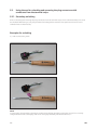
5.2.1. Secondary unlocking
Prior to unlocking and removing the plug connectors from the terminal strips, the so-called secondary fuse must
be unlocked. While doing so, only the prescribed unlocking devices must be used. (see instructions for use of
individual sets of release tools).
Examples for unlocking
a) Take out the safety comb
NOTE:
In some cases, the secondary unlocking is carried out by shifting the safety comb a few mm (pull it out a little)
straigth ahead and thus the safety comb must not be fully removed from the terminal strip.
38
GB
Volkswagen Technical Site: http://vwts.ru http://volkswagen.msk.ru http://vwts.info
огромный архив документации по автомобилям Volkswagen, Skoda, Seat, Audi
Safety comb – another example for unlocking
GB
39
b) Open the flap (see arrow)
40
GB
c) Lock the stop
After locking the stop, pull out the
terminal strip with the plug connectors.
GB
41
5.2.2. Primary unlocking of the plug connectors in the terminal strip
Only use the prescribed unlocking devices according to the operating instructions referring to the individual sets
of release tools for the primary unlocking and removal of the plug connectors from the body of the terminal strips,
as well as for their reinstallation and sealing.
Examples for unlocking
a) Releasing the secondary fuse
Releasing the plug connector with the
prescribed tool
Removing the plug connector with
conductor
42
GB
c) Releasing the secondary fuse
Releasing the plug connector with the
prescribed tool
Removing the plug connector with
conductor
GB
43
d) Releasing the secondary fuse
Releasing the plug connector with the
prescribed tool
Removing the plug connector with
conductor
44
GB
e) Removing the terminal strip with
plug connectors after releasing
the secondary fuse (stop)
Releasing the plug connector with the
prescribed tool
Removing the plug connector with
conductor
GB
45
5.2.3. Installing the conductor with seal in the terminal strip
The procedure is described in the operating instruction for the service case and even for the set of release tools.
Installing the conductor with seal in the terminal strip is described on page 22 of this brochure.
Assembly devices for conductors with seal (set of release tools VAS 1978/35).
46
GB
Examples for installing the conductors with seal in the terminal strips
a) Conductor with plug connector and
seal ready for installation
Inserting the conductor with seal in the
assembly device
GB
47
Inserting the plug connector with seal
into the terminal strip
Pressing the seal into the terminal strip
(up to the stop)
48
GB
b) Conductor with plug connector and
seal ready for installation
Inserting the plug connector with seal
into the terminal strip (with the use of
the assembly device)
Pressing the seal into the terminal strip
(up to the stop)
GB
49
c) Conductor with plug connector and
seal ready for installation
Inserting the conductor with seal in the
assembly device
50
GB
Inserting the plug connector with seal
into the terminal strip
Pressing the seal into the terminal strip
(up to the stop)
Important note
The prerequisite for a successful fault elimination which has been repeated several times in full
scope is also valid for the repairs of plug connectors and terminal strips: Use only recommended tools
and procedures. If a fault occurs by ignoring the rules and recommendations of the manufacturer,
neither the appropriate complaints are acknowledged nor the cost of the repair is covered by the
company Škoda Auto.
GB
51
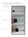
5.2. Selected cases of incorrect repair procedures for plug connectors and terminal strips
a) When repairing the electrical installation of the QC gearbox, the incorrect release tool was used and for
this reason there has been damage to the terminal strip socket and the corresponding pin (it was the
CAN high conductor between the terminal strip T25 and the QC gearbox). The vehicle stopped while
driving and the ESP warning light came on. The cause was the lack of contact on the deformed pin
in the terminal strip (see figure below).
Correct procedure
When repairing plug connectors and terminal strips, always use the recommended tools, devices and
components and proceed according to the manufacturer's recommendations.
52
GB
Notes
Notes
Notes
87
Overview of the previously edited self-study programmes
Mono-Motronic
Central locking
Vehicle alarm
Working with wiring plans
ŠKODA FELICIA
Safety of the ŠKODA vehicles
Principles of ABS - not published
ABS - FELICIA
Immobilizer with transponder
Air conditioning in the vehicle
Air conditioning FELICIA
1.6 engine - MPI 1AV
Four-cylinder diesel engine
Power-assisted steering
ŠKODA OCTAVIA
1.9 ltr. TDI diesel engine
ŠKODA OCTAVIA Convenience electronics system
ŠKODA OCTAVIA Mechanical gearbox 02K, 02J
1.6 ltr. and 1.8 ltr. petrol engines
Automatic gearbox - fundamentals
Automatic gearbox 01M
1.9 ltr./50 kW SDI, 1.9 ltr./81 kW TDI diesel engines
1.8 ltr./110 kW and 1.8 ltr./92 kW petrol engines
OCTAVIA, CAN BUS databus
OCTAVIA - CLIMATRONIC
OCTAVIA - Vehicle safety
OCTAVIA - 1.4 ltr./44 kW engine and gearbox 002
OCTAVIA - ESP - fundamentals, design, function
OCTAVIA 4 x 4 - all-wheel drive
2.0 ltr. 85 kW and 88 kW petrol engines
Radio navigation system - design and function
ŠKODA FABIA - technical information
ŠKODA FABIA - electrical systems
ŠKODA FABIA - electro-hydraulic power-assisted steering
1.4 ltr. - 16 V 55/74 kW petrol engines
ŠKODA FABIA - 1.9 ltr. TDI Unit injection
Mechanical gearbox 02T and 002
ŠkodaOctavia; model 2001
Euro-On-Board-Diagnosis
Automatic gearbox 001
Six-speed gearbox 02M
ŠkodaFabia - ESP
Exhaust emissions
Extended service intervals
Three-cylinder petrol engines 1.2 ltr.
ŠkodaSuperb; Vehicle presentation; part l
ŠkodaSuperb; Vehicle presentation; part ll
ŠkodaSuperb; 2.8 ltr./142 kW V6 petrol engine
ŠkodaSuperb; 2.5 ltr./114 kW TDI V6 diesel engine
ŠkodaSuperb; automatic gearbox 01V
ŠKODA Service®
No.
Designation
51 2.0 ltr./85 kW petrol engine with balancing shafts and
2-stage suction line
52 ŠkodaFabia; 1.4 ltr. TDI engine with the unit injection
system
53 ŠkodaOctavia; Vehicle presentation
54 ŠkodaOctavia; Electrical components
55 FSI petrol engines; 2.0 ltr./110 kW and 1.6 ltr./85 kW
56 Automatic gearbox DSG-02E
57 Diesel engine; 2.0 ltr./103 kW TDI with pump-nozzle units,
2.0 ltr./100 kW TDI with pump-nozzle units
58 ŠkodaOctavia, Chassis and electromechanical
power-assisted steering
59 ŠkodaOctavia RS, 2.0 ltr./147 kW FSI turbo engine
60 2.0 ltr./103 kW 2V TDI diesel engine; particle filter with
additive
61 Radio navigation systems in Škoda vehicles
62 ŠkodaRoomster; Vehicle presentation part l
63 ŠkodaRoomster; Vehicle presentation part ll
64 ŠkodaFabia II; Vehicle presentation
65 ŠkodaSuperb II; Vehicle presentation part l
66 ŠkodaSuperb II; Vehicle presentation part ll
67 2.0 ltr./125 kW TDI diesel engine with Common Rail
injection system
68 1.4 ltr./92 kW TSI petrol engine with turbocharger
69 3.6 ltr./191 kW FSI petrol engine
70 All-wheel drive with Haldex coupling of the lV. generation
71 ŠkodaYeti; Vehicle presentation part l
72 ŠkodaYeti; Vehicle presentation part ll
73 LPG system in Škoda vehicles
74 1.2 ltr./77 kW TSI petrol engine with turbochargersupercharging
75 7-speed dual-clutch automatic gearbox 0AM
76 Green-line vehicles
77 Geometry
78 Passive safety
79 Auxiliary heating
80 2.0 ltr., 1.6 ltr., 1.2 ltr. diesel engines with Common Rail
injection system
81 Bluetooth in Škoda vehicles
82 Vehicle sensor - drive mechanism
83 1.4 ltr./132 kW TSI petrol engine with dual-charging
(compressor, turbocharger)
84 ŠkodaFabia II RS; Vehicle presentation
85 KESSY system in Škoda vehicles
86 START-STOP system in Škoda vehicles
87 Immobilisers in Škoda vehicles
88 Brake and stabilisation systems
89 Sensors in Škoda vehicles - Safety and Convenience
90 Improve customer satisfaction with the help of the
CSS study
91
The paper was made out of chlorine-free bleached cellulose.
1
2
3
4
5
6
7
8
9
10
11
12
13
14
15
16
17
18
19
20
21
22
23
24
25
26
27
28
29
30
31
32
33
34
35
36
37
38
39
40
41
42
43
44
45
46
47
48
49
50
Designation
All rights and technical modifi cations reserved.
S00.2002.91.20 GB Technical status 06/2010
© ŠKODA AUTO a.s.
https://portal.Škoda-auto.com
No.