1
Service Manual
For
Water Purifier, Auto Still
WG203
- Second Edition -
Note:
Use and carry out the instruction manual together on the service of this unit.
Yamato Scientific Co. LTD.
Contents
Specification ............................................................................................... 1
Description and Function of Each Part ..................................................... 2
Main Unit ........................................................................................................................... 2
Control Panel..................................................................................................................... 3
Wiring Diagram ........................................................................................... 4
Piping System View .................................................................................... 5
Principle of Operation ................................................................................ 6
Failure Diagnosis Method .......................................................................... 8
Failure indication and Its Contents ..................................................................................... 8
Remedy for Trouble ......................................................................................................... 10
Parts Replacement Method ...................................................................... 11
Replacement of Heater .................................................................................................... 11
Washing of Distiller .......................................................................................................... 12
Parts Specification ................................................................................... 16
Ceramic Heater ............................................................................................................... 16
Replacement Parts Table ......................................................................... 17
Specification
Performance
Model
WG203
Collecting method
Ion exchange ⇒ Distillation
Sampled pure water
Distilled water/Ion exchange water
Quantity of distilled water
Approx. 1.8/h
Sampling flow rate
1/min. or more (ion exchanged water/distilled water)
Super hard glass
Super hard glass
Ceramic heater 1.4kw
Distiller
Boiler
Condenser
Heater
Configuration
Distilled water storage tank
Raw water side filter
Made of polyethylene, 20
Pre-treatment cartridge (PWF-1), Activated carbon + Hollow yarn film 0.1
μm
Ion exchange resin cartridge
One-touch connection cartridge type (CPC-S), 2×2
Water quality gauge
5 stages lamp display
0 to ∞ ×10-4 S/m•25℃(Display of electric conductivity)
Standard
Water sending pump
Magnet pump
Multi-purpose distilled water
One port on the right side of the unit
sampling port
Raw water pressure range
0.5×100 kPa to 5×100 kPa (0.5 to 5 kgf/cm2)
Ambient temp.
5℃~35℃
Power supply (50/60 Hz)
External dimension (*)
(Width X Depth X Height)
Weight
100V AC 15A
600×560×780 mm
Approx.48 kg
Attached mechanism
Accessories
Water supply hose, drain hose, and connection assembly:
1 respectively
Operation manual: 1
Hose clamp: 1
Scale washing agent (1kg): 1
Pre-treatment cartridge: 1
Ion exchange resin cartridge: 1
Water quality failure arert
Detection of cooling water failure
Prevention of baking heater with no load
Detection of heater disconnection
Prevention of heater overheat
Detection of water leakage
Detection of water outage
Earth leakage breaker
Initial boiled water drain
Detection of water level gauge failure (boiler and tank)
Recovery after power failure
Detection of water quality gauge failure
* : The projection is not included for external dimensions.
1
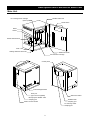
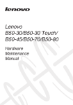
Description and Function of Each Part
Main Unit
Distilled water tank
Ion exchange resin cartridge
(CPC-S)
Reset switch
Boiler
Heater
Heater terminal block
Drain cock
Leakage detection electrode
Water level meter
Pre-treatment cartridge
Control panel
Earth leakage breaker
Drain port
(2pcs each at right/left)
Multi-purpose distilled water
sampling port
Product number sticker
Water level meter
Distilled water
sampling port
Ion exchange water
sampling port
2
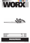
Description and Function of Each Part
Control Panel
①
POWER
⑪
②
ON
DISTILL
CONDUCTIVITY
0
0.5
1
5
10
∞
③
×10-4S/m
⑩
⑨
PRE-FILTER
ION EXCHANGE RESIN
WARNING
LEAK
LOW PRESSURE
⑧
④
⑤
OVERHEAT
PURE
WATER
DISTILLED
WATER
⑦
⑥
① POWER key
Turns on/off the power of the controller.
② DISTILL lamp
Lights up during distillation.
③ CONDUCTIVITY indicator Lights up when the conductivity of pure water keeps between 0.0 to ∞μS/㎝.
④ LOW PRESSURE lamp
Blinks when low pressure error is detected.
⑤ OVERHEAT lamp
Blinks when overheat of the heater is detected.
⑥ DISTILLED WATER key
Starts/stops drawing distilled water.
⑦ PURE WATER key
Starts/stops drawing pure water.
⑧ LEAK lamp
Blinks when water leakage is detected.
⑨
ION EXCHANGE RESIN
exchange indication
PRE-FILTER
⑩
exchange indication
Lights up when the conductivity of the ion exchange resin enters the caution
area (orange), and blinks when it enters the warning area (red).
Lights up when the conductivity of the pretreatment filter enters the caution
area (orange), and blinks when it enters the warning area (red).
⑪ ON lamp
Lights up while the power of the controller is turned on.
3
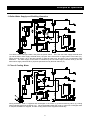
Wiring Diagram
CONT
1A
B
PIO
CN12
T1
1
AC100V
Black
White
2
Black
3
White
Green
4
1
2
CN11
3
4
1
CN13
CN14
CN15
2 CN1
H
X
2
1
3
4
SSR
+ 1
2 CN10
- 3
CN17
2
OH
1
2
1
2
1
2
3
CN16
T2
1
2
CN21
(Attached cable)
10A
B
ELB
1
3
CN18
4
1
2 CN7
3
CN19
1
2
1
2
1
2
Red
X
White
Red
MV1
White
Red
MV2
White
Red
MV3
White
Red
MV4
White
Red
MV5
White
Red
MV6
White
1
Red
2
White
P
Red
1 White
Fs-1
CN2 2 Black
3
1
2
CN8
3
4
5
E
1
Fs-2
4
1
1
2 CN9
3
WL
Red
White
2
CN3 3 Black
Red
CN4 2 White
Black
Fs-3
3
1
CN5 2
1
White
Black
Brown
CN6 2
3
4
Symbol
Symbol
Part name
Earth leakage breaker
Terminal block
Heater
Temperature sensor
X
MV1
MV2
MV3
Ion exchange water quality gauge
MV4
WL
Water leakage detector
MV5
FS1
Control float switch
MV6
FS2
FS3
PS
SW
Control float switch
Water level float switch
Pressure switch
Reset switch
Main relay
Raw water solenoid valve
Boiler water supply solenoid valve
Cooling water solenoid valve
Initial accumulated water drain solenoid
valve
Distilled water sampling solenoid valve
Ion exchange water sampling solenoid
valve
Distilled water sampling pump
Solid state relay
Display board
PLANAR board
ELB
T1, T2
H
OH
E
Part name
Orange
P
SSR
PIO
CONT
4
Ps
SW
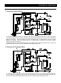
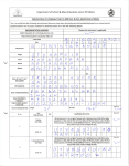
Piping System View
1
Pressure reduction valve
15 Boiler water supply solenoid valve
2
Pressure switch
16
3
Cooling water solenoid valve
17 Ion exchange water sampling solenoid valve
4
Raw water supply solenoid valve
18 Distilled water sampling solenoid valve
5
Pre-treatment cartridge
19 Ion exchange water sampling port
6
Ion exchange resin cartridge (CPC-S)
20 Distilled water sampling port
7
Float cylinder
21 Distilled water tank
8
Float switch 1
22 Float switch 3
9
Float switch 2
23 Air filter
Initial accumulated water drain
solenoid valve
10 Boiler drain cock
24 Distilled water sampling pump
11 Boiler
25 Distilled water tank drain port
12 Heater
26 Water level meter
13 Condenser
27 Multi-purpose distilled water sampling port
14 Ion exchange water quality gauge electrode
5
Principle of Operation
1. Boiler Water Supply and Distilling Operation
Turn ON the earth leakage breaker, and press the power switch. Then, the raw water supply solenoid valve
(4) and the boiler water supply solenoid valve (15) open at the same time to supply water to the boiler (11).
When the float switch 1 (8) in the float cylinder (7) detects water level, the heater (12) is energized to start
distillation. The water supply to the boiler is controlled by the raw water supply solenoid valve (4) and the
boiler water supply solenoid valve (15) both opened/closed by the float switch 2 (9).
2. Flow of Cooling Water
During distillation, water is supplied and discharged in the order: (1) pressure-reducing valve, (3) cooling
water solenoid valve and condenser (13). When the distilled water tank is full, or when ion exchanged water
is sampled, distillation is stopped, and the cooling water is also stopped automatically.
6
Principle of Operation
3. Sampling of Distilled Water
The distilled water condensed in the condenser (13) is stored in the distilled water tank (21) after discharging
the initial boiled water via the initial boiled water discharge solenoid valve (16) for about 10 min. after power
switch is turned ON. If the float switch (22) on top of the tank trips, it is deemed as Full Tank, and the
distillation is stopped. When any specified amount of distilled water is sampled and consumed, distilled
water is produced automatically.
The distilled water so stored is sampled by way of the distilled water sampling solenoid valve (18) and the
distilled water sampling port (20) by the distilled water sampling pump (24).
4. Sampling Ion Exchanged Water
Ion exchange water is sampled by way of the pressure-reducing valve (1), raw water supply solenoid valve
(4), pre-treatment cartridge (5), ion exchange resin cartridge (6), ion exchange water quality electrode (14),
ion exchange water sampling solenoid valve (17) and ion exchange water sampling port (19).
7
Failure Diagnosis Method
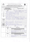
Failure indication and Its Contents
When the following error signs appear, memorize the sign and turn the tap off immediately. If an error
occurs, part change or unit check becomes required. Please call the shop from which you made a
purchase or our customer support center. In that case, please notify them of the error sign.
Indication
Safety device
Burnout of heater
Overheat of
heater
Water level error
of boiler
LEAK
LOW
PRESS
URE
Lights
up
When temperature of the
heater did not rise after
Blinks
certain time passed during
distillation
Change the heater.
Lights
up
Change the heater.
Turns
off
When the temperature at
the heater excesses the
error judgment value, or
Blinks
when
breakage
or
shortage occurs on the
temperature sensor
Turns
off
Turns
off
Coolant error
Turns
off
Water level
meter error
Lights
up
Tank water level
meter error
Pure water
conductivity
meter error
Blinks
Lights
up
OVER
HEAT
Cause
Symptom
Countermeasure
Turns
off
When
the
heater
operation water level input
kept OFF even if the time
for required to evaluate
the boiler water level error
passed after starting water
supply to the boiler
Turns
off
Lights
up
When the state of the
boiler water overflow input
ON in the float pipe
continued longer than
coolant error judgment
time
Blinks
Lights
up
When the condition of the
float contacting points in
the float pipe becomes
abnormal.
Change
switch.
When the condition of
the float contacting points
in the tank water level
meter becomes abnormal
Turn the breaker on
again. If the trouble
persists, please call
our customer service
center.
When
the
state
of
breakage or shortage of
the thermistor sensor for
pure water conductivity
meter continues longer
than error judgment time
Change the pure
water
conductivity
sensor.
Lights
up
Lights
up
Lights
up
Lights
up
Lights
up
8
Check
whether
manual drain cock is
opened or not. Also
check the feedwater
solenoid valve and
the feedwater path.
All controls
Check the coolant
of the heater
solenoid valve and
and solenoid
the coolant path.
valve
are
turned OFF.
the
float
Failure Diagnosis Method
Failure indication and Its Contents
Indication
Safety device
Low pressure
error
Controller error
LEAK
Turns
off
Blinks
LOW
PRESS
URE
Blinks
Blinks
OVER
HEAT
Turns
off
Cause
When raw water pressure
is low, or the pressure of
raw water is less than
0.5kgf/cm2
When the setting value
which is memorized in the
memory chip cannot be
read properly, or when an
Blinks abnormal
value
was
displayed
Symptom
Countermeasure
Check
the
water
pressure
of
raw
water and the tap.
When the raw water
pressure
is
recovered, operation
starts automatically
(auto-recovery)
Turn
All controls OFF.
of the heater
and solenoid
valve
are
turned OFF.
the
breaker
When an error at A/D
circuit is detected
Water leakage
error
Blinks
Turns
off
Turns
off
When
the
resistance
value of the water leakage
sensor input becomes
less than the water
leakage error judgment
value
9
Turn the breaker off
and check the piping
parts. For details,
refer to page 10.
Failure Diagnosis Method
Remedy for Trouble
Remedy when water leakage detection ("LEAK" lights up)
1. Turn "OFF" the earth leakage breaker on the right side of body.
2. When restarting after the faulty portion is repaired, wipe off water accumulated at the bottom of
system, dry up, remove the water leakage detection electrode, and dry up enough.
3. Be sure to reset the electrode to the original condition.
4. Close the door.
5. Turn on the earth leakage breaker and press the POWER key. Normal operation is started
because faulty portion is repaired.
Water leakage detection electrode
Remedy when water stopping detection ("LOW PRESSURE" lights up)
1. Check the pressure of the raw water and if the tap is open (if water level reaches the device).
2. If the pressure of the raw water resumes, the system is reset automatically.
Remedy when overheat detection ("OVERHEAT" lights up)
1. Check if the cooling water flows.
2. If the cooling water flows, the heater may be overheated or disconnected.
3. In such a case, contact the distributor or the customer support center.
10
Parts Replacement Method
Replacement of Heater
If the heater should be disconnected or damaged due to deposit of scale, replace it by the
procedure below. (Also refer to Page 12 "Washing of Distiller" in working.)
1. Turn "OFF" the earth leakage breaker of this unit.
2. Close the tap.
3. Turn "OFF" earth leakage breaker, and when more than 30 minutes has passed, open the front door
of this unit, and open the boiler water drain cock.
4. Open the left side plate of the body, loosen the four screws on the right of the terminal block, and
disconnect the heater lead terminal.
5. Pull the heater lead out of the grommet.
6. Remove the cap nut of heater, and pull out the heater.
7. Remove the packing and cap nut from the damaged heater.
8. Install the packing and cap nut on the new heater. At that time, do not touch with bare hand in order
to prevent soiling by hand.
Packing
9. Install on the boiler so that "YK-W-3" mark of the heater is faced up.
10.Feed the heater lead wire through the grommet, check the heater lead wire attaching position, and
secure to the terminal block.
11. Mount the left side plate.
12.Close the boiler water drain cock.
13.Close the front door, and then open the tap.
14.Turn on the earth leakage breaker.
15.Press POWER key while holding down PURE WATER key and DISTILLED WATER key.
Perform calibration operation (all of ON, DISTILL, PURE WATER, and DISTILLED WATER lamps
blink at the same time) for about five minutes, after then, distillation (ON and DISTILL lamps light up)
starts automatically. Key operation becomes disable while calibration operation. In case that power
failure occurs while calibration operation, please perform calibration again.
11
Parts Replacement Method
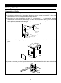
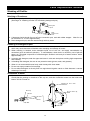
Washing of Distiller
Dismounting of Distiller
1. Turn "OFF" the earth leakage breaker of the unit.
2. Close the tap.
3. Check that the boiler is not hot (longer than 30 minutes after the breaker is turned "OFF"), then open
the front door of the unit, and open the boiler water drain cock.
4. Disconnect the hose connected to the boiler ① and condenser ②. In disconnecting from the
distilled water outlet and boiler water supply and drain port, turn the hose band by use of tool and
displace the engaged portion (serrated portion). Take care in disconnecting because excessive
force applied to glass may cause damage.
②
Cooling Water
Outlet
Cooling Water
Inlet
Distilled
Water
Outlet
①
Boiler Water Supply and
Drain Port
5. Disconnect the hole plug at left plate, remove four screws with a screw driver, then remove the left
plate.
6. Loosen 4 screws on the right of terminal block located at the right top of the body frame with left side
plate dismounted by use of Phillips screwdriver, and disconnect the heater lead terminal.
12
Parts Replacement Method
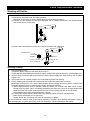
Washing of Distiller
7.
1) Disconnect the heater lead wire from grommet.
Note that, do not bend or pull the heater lead wire more than necessary.
2) Remove the two screws of boiler securing band with a Phillips screwdriver, and take the boiler
and condenser out of the body.
Grommet
3) Loosen the knurled screws (three) and remove the boiler and condenser.
Grommet
Condenser
Knurled Screw
Connecting
Hardware
Packing
Boiler
Connection Port
with Condenser
Washing of boiler
1. Adjust detergent liquid.
1) Prepare approx. 2 liters of hot water at 50 to 60C.
2) Add attached scale detergent (Orgazor) approx. 200g to hot water prepared in 1) and agitate well.
2. Seal the hose connection port at the bottom of boiler (boiler supply and drain port) by use of rubber
stopper, etc.
3. Secure the boiler at a stable position to prevent washing liquid from spilling.
4. Pour in washing liquid through connection port with condenser with heater turned on.
Most scale is removed in 4 to 5 hours approximately. Drain washing liquid in the boiler. If much scale
is distiller deposited, pour in washing liquid newly, and repeat washing
1) When scale-removing work is finished, take the heater out of boiler and wash each of them
enough with city water. Here, in washing the heater with water, be sure to fill a larger beaker with
water and wash the heater inside so that lead wire and its routing port are not wet by water.
Avoid washing the heater directly with water from tap.
2) If solid scale distiller remains after washing by washing liquid, follow the remedy below:
Boiler: Scrub with brush etc. for removing.
Heater: Scrub with something soft such as wood piece or plastic.
In this connection, remove scale on the heater uniformly in general, never leaving solid scale in part. In
an extreme case, only such part has a great heat resistance, causing damage to the heater.
13
Parts Replacement Method
Washing of Distiller
Washing of Condenser
1. Pour detergent liquid into the cooling pipe of condenser.
(See Page 13 "Washing of boiler" for formulating detergent liquid.)
Detergent
Liquid
Hose
Connection
Port
2. If detergent liquid should flow out of hose connection port, seal with rubber stopper. Most fur can
be removed in 4 - 5 hours approximately.
3. Drain detergent liquid, and then wash enough with city water.
Handling of Detergent Liquid
1. Wash the boiler and heater sooner. If the more scale is deposited, the more difficult is its removal,
which may cause decrease of distilled water sampling and damage to heater.
2. When washing is finished, drain detergent liquid out of the unit, and apply neutralization by
neutralizer (such as sodium hydroxide). In neutralization, check that it is neutral by use of pH test
paper, etc. (Principal component of scale detergent: Sulfamic acid and pH of water solution: Acidic
approximately 1)
3. In storing this detergent, seal the agent and store in cold and dark place avoiding high temperature
and humidity.
4. In handling this detergent, be sure to use protective tools (gloves, mask, and glasses).
5. When it is in contact with human body, wash it away with clean water.
6. Do not use empty container for beverage.
7. Do not allow detergent to directly flow into agricultural irrigation canal or fields because it causes
withering of rice crop.
Installation of boiler
1. Secure the boiler with the boiler securing band so that connection port of condenser is horizontal.
Check that the packing is contained in the cap nut, and then install the heater into the boiler with
letters "YK-W-3" faced up.
Connection Port with
Condenser
Packing
Boiler Securing
Band
YK-W-3
Heater
Cap Nut
14
Parts Replacement Method
Washing of Distiller
2. Attach 4 heater lead terminals to the terminal block.
Heater Lead
(wire diameter, thick)
Heater Lead
(wire diameter, thin)
3. Install the left side plate on the body.
4. Insert the hose to the boiler water supply and drain port, and secure with the hose band.
Installation of condenser
1. Place packing in the connection port of boiler with condenser, and secure with connecting hardware
so that the boiler and condenser are placed in the same direction.
Inlet
Outlet
Boiler
Connecting
Hardware
Condenser
View from above
2. Connect the hose respectively to the cooling water inlet, outlet, and distilled water outlet of
condenser.
3. Close the boiler water drain cock.
Boiler Water
Drain Cock
Open
Close
15
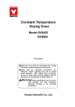
Parts Specification
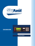
Ceramic Heater
Model: YK-W-3
Specification:
Resistance of heater unit: 4.84Ω±10%(at23℃)
At stabilized boiling condition: Approx. 1400W
Resistance of sensor unit: 400Ω±10%(at23℃)
Resistance of sensor (Ω )
650
Resistance (Ω )
600
550
500
450
400
350
300
23
50
70
90
105 125
Temperature (℃)
145
160
Note)
The current of approximately 20A passes for a very short period just after the current is supplied
when the heater is cold. The current, however, soon decreases.
When the heater is removed for replacement, make sure that the boiler has been drained and the
heater has been sufficiently cooled down.
Do not touch the heating unit even after removed.
16
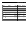
Replacement Parts Table
Symbol
ELB
Part Name
Code No.
Specification
Manufacturer
Earth leakage breaker
LT00029776
NV-L22GR 20A
T1, T2
Terminal block
A0050115
TB-20C
H, OH
Heater (temperature sensor)
2420016003
YK-W-3
Yamato Scientific
Ion exchange water quality gauge
1011890001
For WG25/220
Yamato Scientific
WL
Water leakage detector
WG55005328
lead wire 2,7m
Yamato Scientific
Fs-1
Control float switch
LT00014441
WA050514-2
Yamato Scientific
Fs-2
Control float switch
LT00014440
WA050514-1
Yamato Scientific
Fs-3
Water level float switch
LT00014439
YF4-1888
Yamato Scientific
Ps
Pressure switch
2040040001
ST-B-BR1-N2
SW
Reset switch
2010010014
A2A-4W
OMRON
Main relay
2050000056
G7L-1A-TUB 100V
OMRON
MV1
Raw water solenoid valve
LT00014451
AG3X-A300-100V
CKD
MV2
Boiler water supply solenoid valve
LT00014450
J241-811
CKD
MV3
Cooling water solenoid valve
LT00014453
AB2X-1242
CKD
MV4
Initial accumulated water drain solenoid
LT00014450
valve
J241-811
CKD
MV5
Distilled water sampling solenoid valve
LT00014450
J241-811
CKD
MV6
Ion exchange water sampling solenoid
LT00014450
valve
J241-811
CKD
Distilled water sampling pump
2150080001
MD-10A
IWAKI
SSR
Solid state relay
2160000035
TRS5225
Toho Denshi
PIO
Display board
LT00013590
WG203
Yamato Scientific
PLANAR board
LT00013589
WG203
Yamato Scientific
E
X
P
CONT
17
4P
Mitsubishi
SAKAZUME
Sanyo Keiki
Service Manual for
Water Purifier, Auto Still
WG203
Second Edition April 22, 2008
Revision
July 1, 2015
Yamato Scientific Co., Ltd.
2-2-1 Nihonbashi Muromachi, Chuo-ku,
Tokyo, 103-0022, Japan
http://www.yamato-net.co.jp
18